POWER DISTRIBUTION
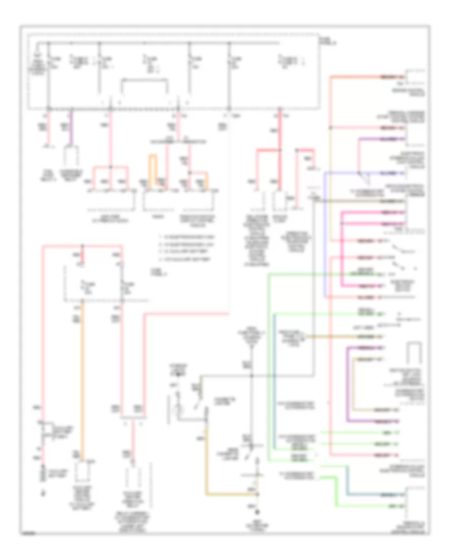
Power Distribution Wiring Diagram (1 of 6) for Volkswagen CC VR6 4Motion 2011

List of elements for Power Distribution Wiring Diagram (1 of 6) for Volkswagen CC VR6 4Motion 2011:
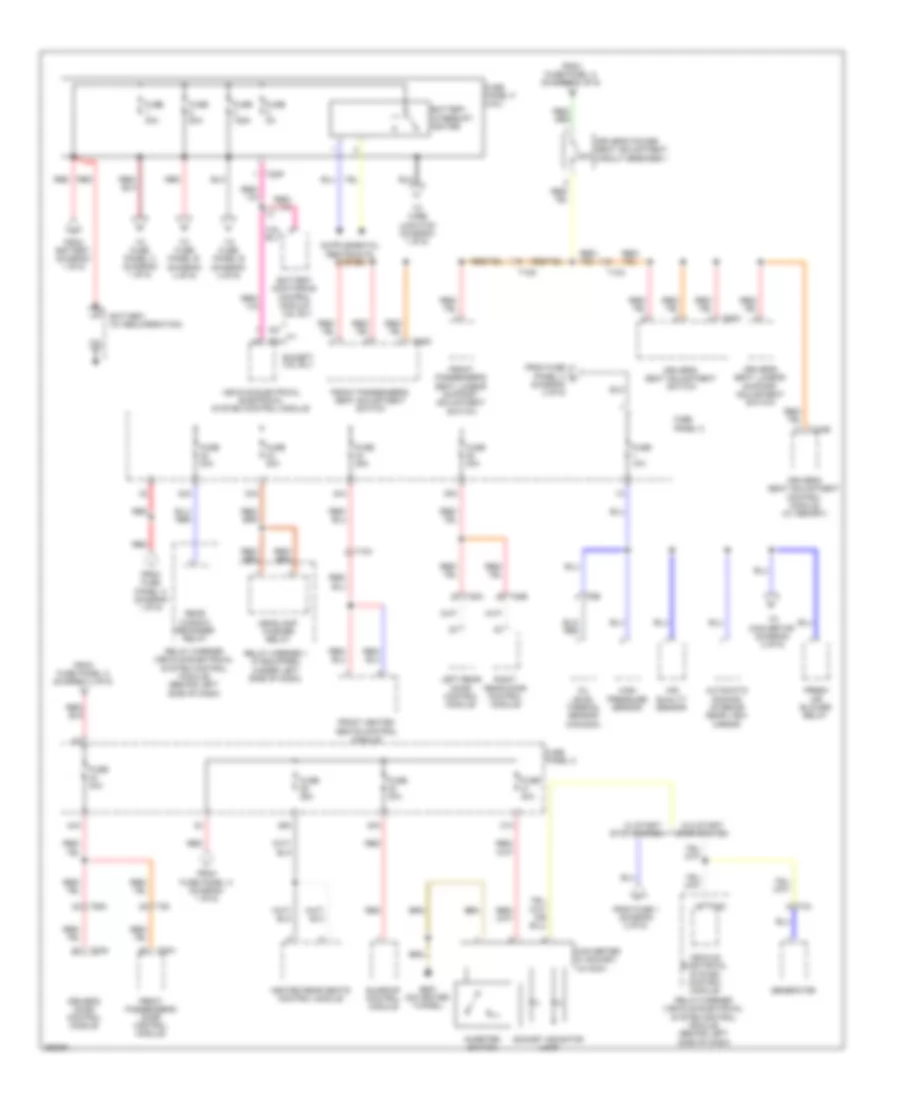
Power Distribution Wiring Diagram (2 of 6) for Volkswagen CC VR6 4Motion 2011
List of elements for Power Distribution Wiring Diagram (2 of 6) for Volkswagen CC VR6 4Motion 2011:
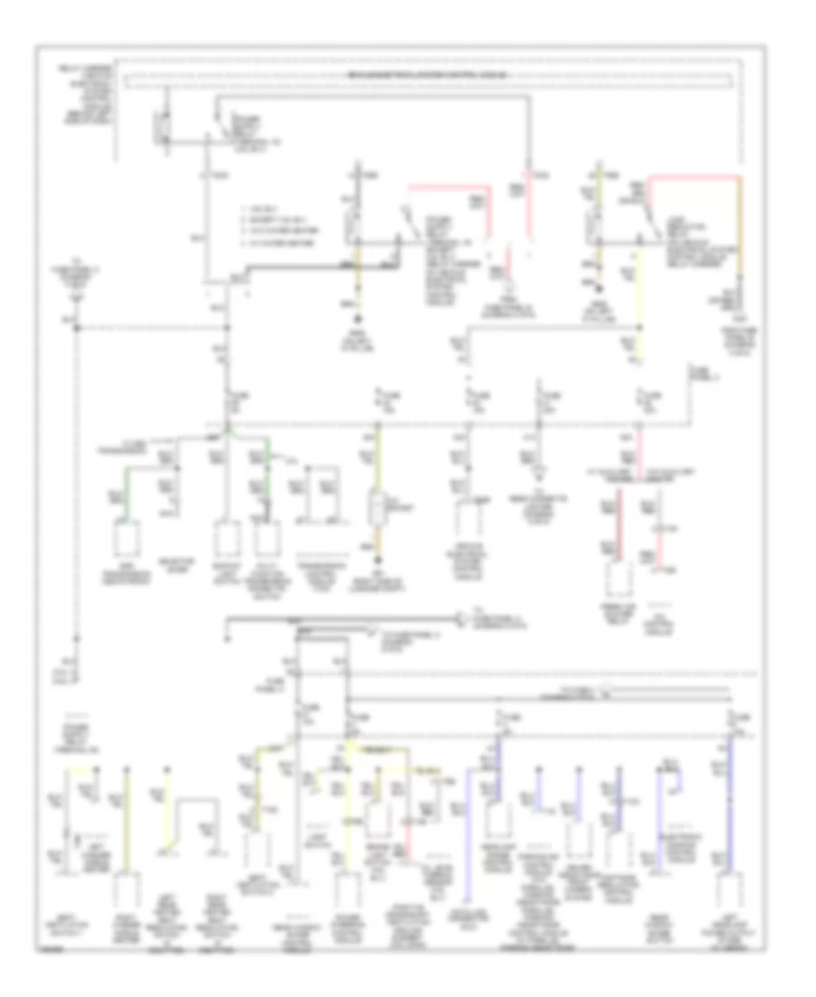
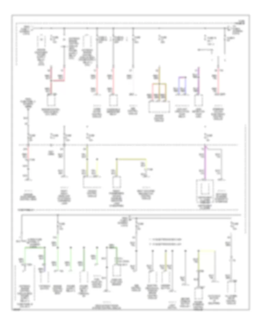
Power Distribution Wiring Diagram (3 of 6) for Volkswagen CC VR6 4Motion 2011
List of elements for Power Distribution Wiring Diagram (3 of 6) for Volkswagen CC VR6 4Motion 2011:
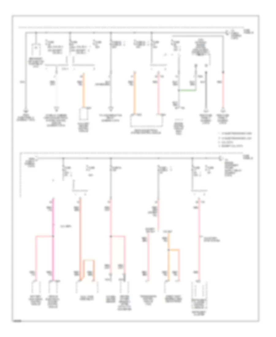
Power Distribution Wiring Diagram (4 of 6) for Volkswagen CC VR6 4Motion 2011
List of elements for Power Distribution Wiring Diagram (4 of 6) for Volkswagen CC VR6 4Motion 2011:
Power Distribution Wiring Diagram (5 of 6) for Volkswagen CC VR6 4Motion 2011
List of elements for Power Distribution Wiring Diagram (5 of 6) for Volkswagen CC VR6 4Motion 2011:
Power Distribution Wiring Diagram (6 of 6) for Volkswagen CC VR6 4Motion 2011
List of elements for Power Distribution Wiring Diagram (6 of 6) for Volkswagen CC VR6 4Motion 2011: