POWER DISTRIBUTION
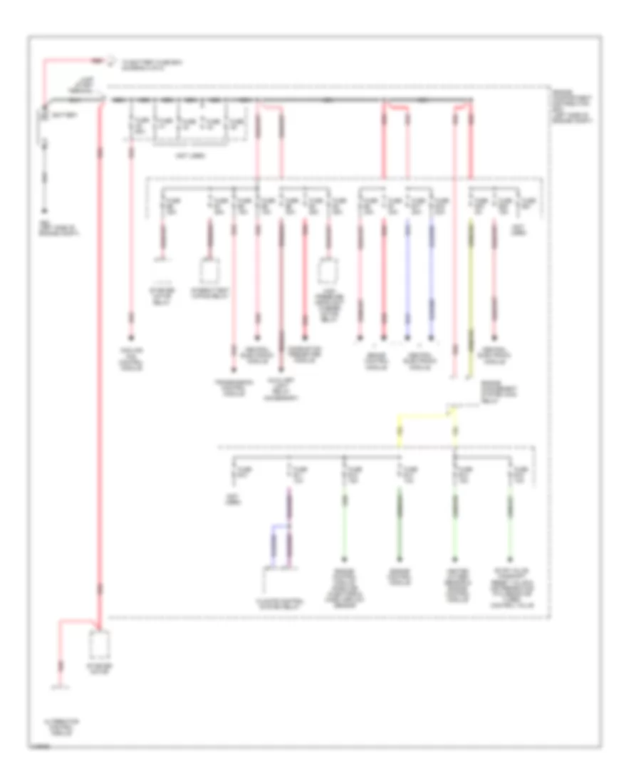
Power Distribution Wiring Diagram, Early Production (1 of 2) for Volvo XC90 2005

List of elements for Power Distribution Wiring Diagram, Early Production (1 of 2) for Volvo XC90 2005:
- (at left side of engine compt)
- (at left side of engine compt, forward of strut tower) engine compartment fuse box
- (not used)
- 15/30
- Battery
- Brake control module
- Canister shut-off valve
- Central electronic module
- Climate control system relay
- Combustion preheater module
- Cooling fan control module
- Engine compartment cooling fan electrics box
- Engine control module
- Engine control module, gasoline injectors & mass airflow sensor
- Engine management system main relay
- Evap valve, camshaft reset valve & air preheating ptc resistor turbo control valve
- Extra light relay
- Fuel system relay
- Fuse a1 60a
- Fuse a2 40a
- Fuse a3 40a
- Fuse a4
- Fuse a8 60a
- Fuse b1 25a
- Fuse b11 20a
- Fuse b12 5a
- Fuse b13 25a
- Fuse b14 30a
- Fuse b15 35a
- Fuse b17 20a
- Fuse b18 15a
- Fuse b19 30a
- Fuse b2 20a
- Fuse b20 20a
- Fuse b21 15a
- Fuse b22 35a
- Fuse b23 10a
- Fuse b3 10a
- Fuse b4 20a
- Fuse b5 10a
- Fuse b6 15a
- Fuse b7
- Fuse b8 10a
- Fuse b9 10a
- G53
- Generator
- Glow plug unit relay
- Heated oxygen sensor & engine control module
- High pressure headlight washer motor
- High pressure headlight washer motor relay
- Intermittent windshield wiper relay
- Jump start terminal
- Low/high speed windshield wiper relay
- Red
- Sensor accelerator
- Spark plug & ignition coil
- Starter motor
- Starter motor relay
- To battery fuse box (diagram 2 of 2)
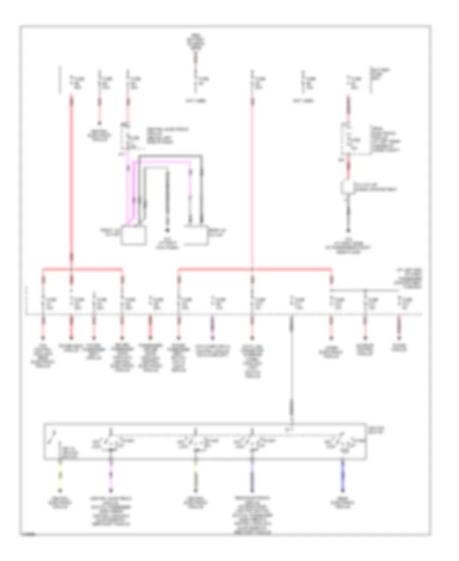
Power Distribution Wiring Diagram, Early Production (2 of 2) for Volvo XC90 2005
List of elements for Power Distribution Wiring Diagram, Early Production (2 of 2) for Volvo XC90 2005:
- (at left end of dash) passenger compartment fuse box
- (not used)
- (suspension module)
- 12v outlet cargo compartment
- A red
- A17
- Acc
- B31
- Battery fuse box
- Central electronic module
- Central electronic module (behind left side of dash)
- Data link connector, steering wheel module & light switch module
- Driver/ passenger door module & central electronic module
- Fan control module & rear electronic module
- From battery (diagram 1 of 2)
- Front 12v outlet
- Fuse 15a
- Fuse c1 30a
- Fuse c10 5a
- Fuse c11 7.5a
- Fuse c12 10a
- Fuse c13 15a
- Fuse c14 5a
- Fuse c2 30a
- Fuse c3 25a
- Fuse c4 25a
- Fuse c5 25a
- Fuse c6 25a
- Fuse c9 10a
- Fuse e1 60a
- Fuse e2 40a
- Fuse e3
- Fuse e4 50a
- Fuse e5 50a
- Fuse e6 50a
- Fuse e7 50a
- G10 (at right kick panel)
- G73 (at right rear of passenger's compt, near floor)
- Ignition switch
- Key in ignition switch
- Lock
- Nca
- Off
- Passenger/ driver door module & central electronic module
- Phone module
- Power passenger seat module
- Power passenger seat, switch unit & audio module
- Power seat module
- Rear 12v outlet
- Rear electronic module
- Rear electronic module (at left rear corner of cargo compt)
- Red
- Rti display control module, cd player (mp2) & control module cd player (mp1)
- Start
- Sunroof control module
- Upper electronic module
Power Distribution Wiring Diagram, Late Production (1 of 2) for Volvo XC90 2005
List of elements for Power Distribution Wiring Diagram, Late Production (1 of 2) for Volvo XC90 2005:
- (left side of engine compt)
- (not used)
- Alternator control module
- Auxiliary light relay (accessory)
- Battery
- Brake control module
- Central electronic module
- Climate control system relay
- Combustion preheater module
- Cooling fan control module
- Engine compartment distribution box (left side of engine compt)
- Engine control module
- Engine control module gasoline injectors & mass airflow sensor
- Engine management system main relay
- Evap valve, camshaft reset valve & air preheating ptc resistor turbo control valve
- Fuse a1
- Fuse a2 60a
- Fuse a3
- Fuse a4
- Fuse a5
- Fuse b1 30a
- Fuse b10
- Fuse b11 10a
- Fuse b12 15a
- Fuse b13 10a
- Fuse b14 15a
- Fuse b15 10a
- Fuse b16 20a
- Fuse b17 20a
- Fuse b19 5a
- Fuse b2 30a
- Fuse b20 15a
- Fuse b21
- Fuse b3 35a
- Fuse b4 25a
- Fuse b5 20a
- Fuse b6 35a
- Fuse b7 25a
- Fuse b8 15a
- Fuse b9 15a
- G53
- Heated oxygen sensor & engine control module
- High pressure headlight washer motor relay
- Intermittent wiping relay
- Jump start terminal
- Nca
- Red
- Starter motor
- Starter motor relay
- To battery fuse box (diagram 2 of 2)
- Transmission control module
Power Distribution Wiring Diagram, Late Production (2 of 2) for Volvo XC90 2005
List of elements for Power Distribution Wiring Diagram, Late Production (2 of 2) for Volvo XC90 2005:
- (at left end of dash) passenger compartment fuse box
- (not used)
- (suspension module)
- 12v outlet cargo compartment
- A red
- A17
- Acc
- B31
- Battery fuse box
- Cd player (mp2) & control module cd player (mp1)
- Central electronic module
- Central electronic module (behind left side of dash)
- Data link connector, steering wheel module & light switch module
- Driver/ passenger door module & central electronic module
- Fan control module & rear electronic module
- From battery (diagram 1 of 2)
- Front 12v outlet
- Fuse 15a
- Fuse c1 30a
- Fuse c10 5a
- Fuse c11 7.5a
- Fuse c12 10a
- Fuse c13 15a
- Fuse c14 5a
- Fuse c2 30a
- Fuse c3 25a
- Fuse c4 25a
- Fuse c5 25a
- Fuse c6 25a
- Fuse c9 10a
- Fuse e1 60a
- Fuse e2 40a
- Fuse e3
- Fuse e4 50a
- Fuse e5 50a
- Fuse e6 50a
- Fuse e7 50a
- G10 (at right kick panel)
- G73 (at right rear of passenger's compt, near floor)
- Ignition switch
- Key in ignition switch
- Lock
- Nca
- Off
- Passenger/ driver door module & central electronic module
- Phone module
- Power passenger seat module
- Power passenger seat, switch unit & audio module
- Power seat module
- Rear 12v outlet
- Rear electronic module
- Rear electronic module (at left rear corner of cargo compt)
- Red
- Start
- Sunroof control module
- Upper electronic module