SUPPLEMENTAL RESTRAINTS
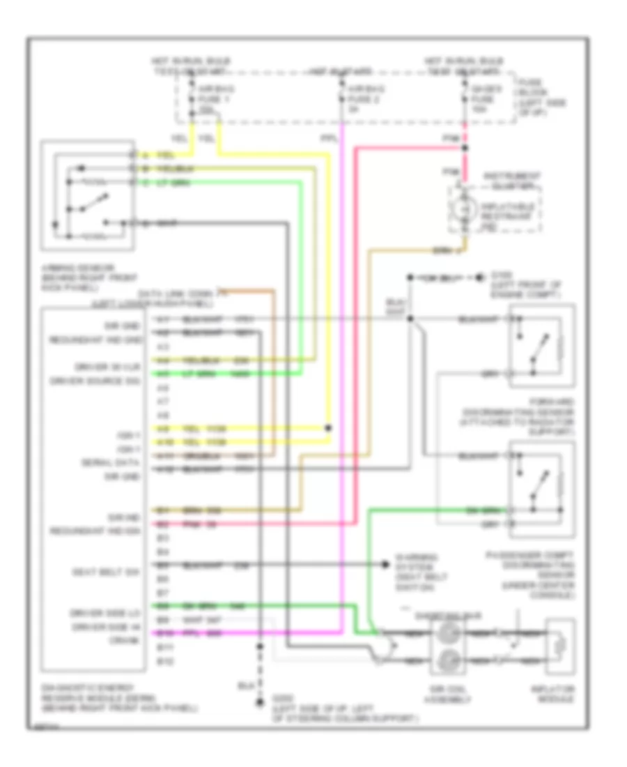
Supplemental Restraint Wiring Diagram for Buick Skylark Custom 1995
List of elements for Supplemental Restraint Wiring Diagram for Buick Skylark Custom 1995:
- A10
- A11
- A12
- Air bag fuse 1 15a
- Air bag fuse 2 3a
- Arming sensor (behind right front kick panel)
- B10
- B11
- B12
- Crank
- Diagnostic energy reserve module (derm) (behind right front kick panel)
- Driver 36 vlr
- Driver side hi
- Driver side lo
- Driver source sig
- Forward discriminating sensor (attached to radiator support)
- Fuse block (left side of i/p)
- G100 (left front of engine compt)
- G202 (left side of i/p, left of steering column support)
- Gages fuse 10a
- Hot in run, bulb test or start
- Hot in start
- Ign 1
- Inflatable restraint ind
- Inflator module
- Instrument cluster
- L data link conn (left lower hush panel)
- Nca
- Passenger compt discriminating sensor (under center console)
- Pnk
- Redundant ind gnd
- Redundant ind ign
- Seat belt sw
- Serial data
- Shorting bar
- Sir coil assembly
- Sir gnd
- Sir ind
- Warning system (seat belt switch)
 Čeština
 Dansk
Dansk Deutsch
 Ελληνικά
 English
 English
 Español
 Suomi
Suomi Français
 Français
 עברית
עברית Hrvatski
 Magyar
 Italiano
 日本語
日本語 한국어
한국어 Nederlands
 Polski
 Português
 Română
 Русский
 Slovenčina
 Slovenščina
 Svenska
 Türkçe
 中文 (中国)
 Português