ANTI-LOCK BRAKES
Anti-lock Brakes Wiring Diagram for Audi S4 Avant Quattro 2006
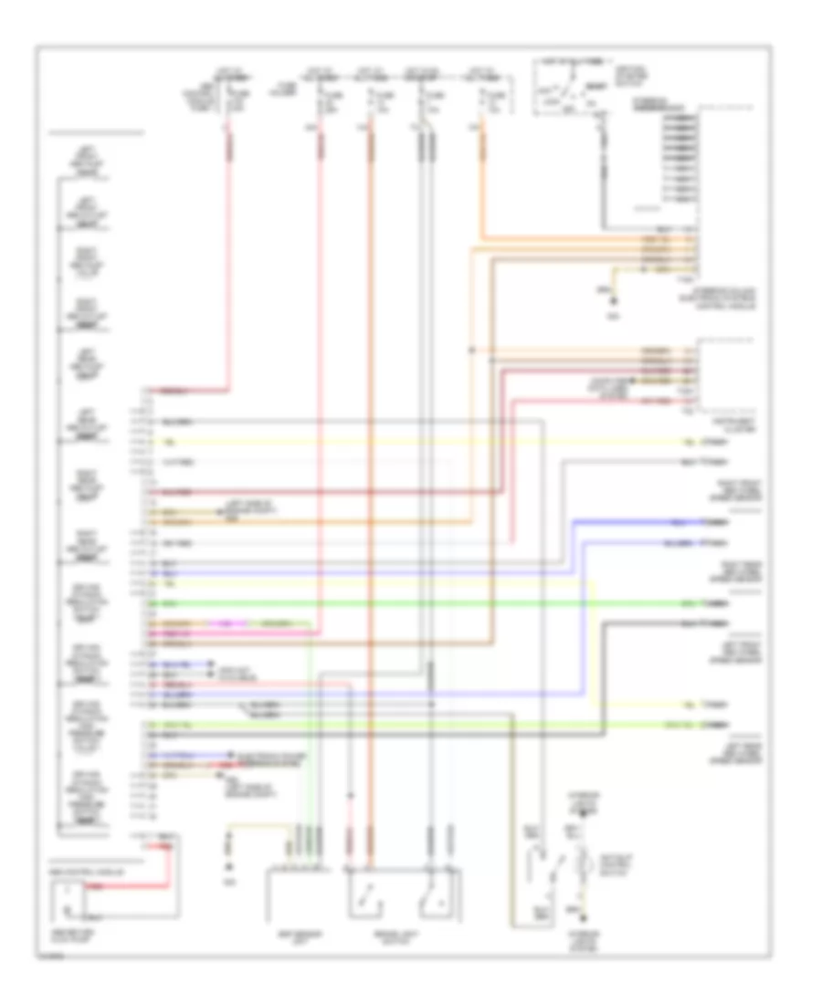
List of elements for Anti-lock Brakes Wiring Diagram for Audi S4 Avant Quattro 2006:
- (info not available)
- (left side of engine compt) g26
- Abs control module
- Abs control module fuse 1
- Abs return flow pump
- Acc
- Anti-slip control switch
- Brake light switch
- Computer data lines system
- Driving dynamic regulation high pressure switch valve 1
- Driving dynamic regulation high pressure switch valve 2
- Driving dynamic regulation switch valve 1
- Driving dynamic regulation switch valve 2
- Electronic power steering system
- Esp sensor unit
- Fuse 10a
- Fuse 25a
- Fuse 40a
- Fuse holder
- G26 (left side of engine compt)
- G33
- Hot at all times
- Hot in on or start
- Ignition/ starter switch start
- Instrument cluster
- Interior lights system
- Left front abs inlet valve
- Left front abs outlet valve
- Left front abs wheel speed sensor
- Left rear abs inlet valve
- Left rear abs outlet valve
- Left rear abs wheel speed sensor
- Lock
- Nca
- Off
- Red
- Right front abs inlet valve
- Right front abs outlet valve
- Right front abs wheel speed sensor
- Right rear abs inlet valve
- Right rear abs outlet valve
- Right rear abs wheel speed sensor
- Steering angle sensor
- Steering column electronic systems control module
- T16a
- T32
- T32a
 Čeština
 Dansk
Dansk Deutsch
 Ελληνικά
 English
 English
 Español
 Suomi
Suomi Français
 Français
 עברית
עברית Hrvatski
 Magyar
 Italiano
 日本語
日本語 한국어
한국어 Nederlands
 Polski
 Português
 Română
 Русский
 Slovenčina
 Slovenščina
 Svenska
 Türkçe
 中文 (中国)
 Português