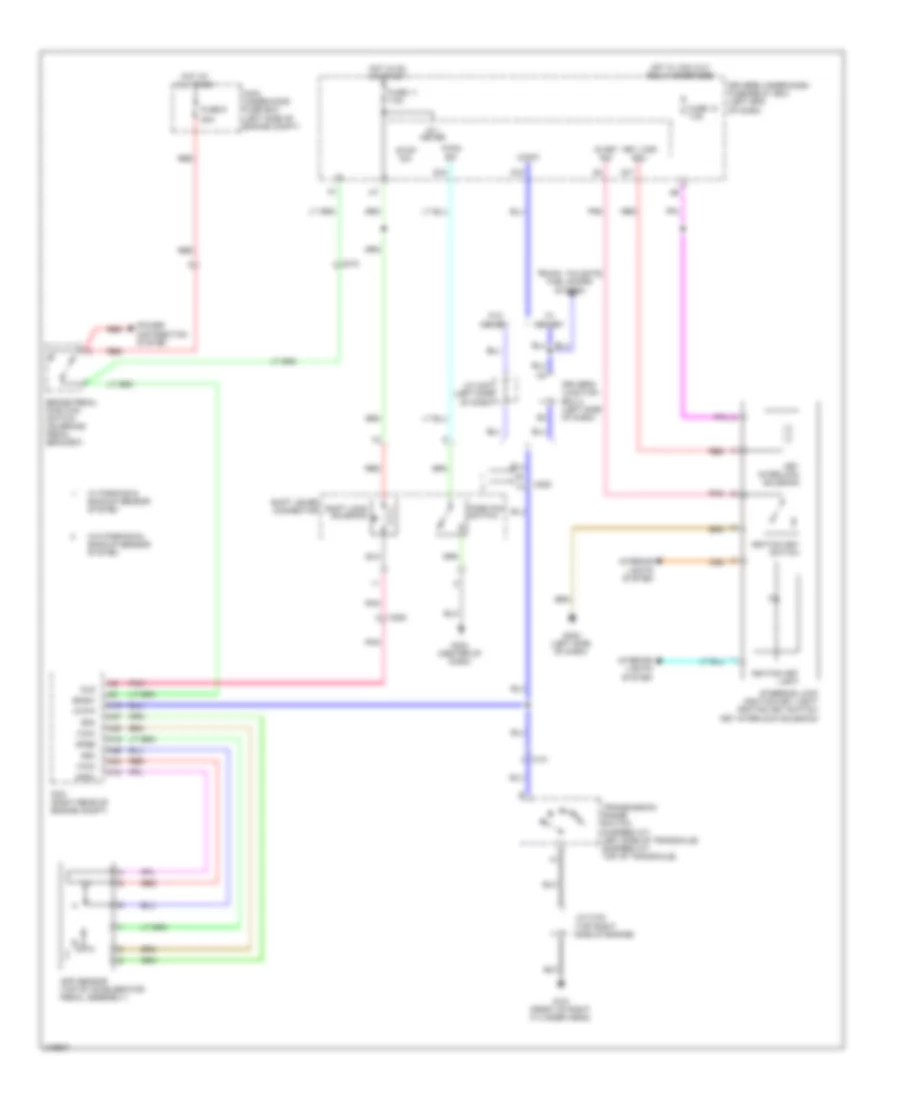
SHIFT INTERLOCK
Shift Interlock Wiring Diagram for Honda Odyssey Touring 2013
List of elements for Shift Interlock Wiring Diagram for Honda Odyssey Touring 2013:
- 20a
- A16
- A18
- A19
- A24
- A25
- A26
- A27
- App sensor (top of accelerator pedal assembly)
- Apsa
- Apsb
- Atp-p
- Bksw
- Brake pedal position switch (on brake pedal bracket)
- C101
- C205
- C212
- Driver's junction box 2 (left side of dash)
- Driver's under-dash fuse/relay box (left end of dash)
- Fuse 11 7.5a
- Fuse 13 7.5a
- Fuse 9
- G101 (front of right cylinder head)
- G402 (left side of dash)
- G403 (center of dash)
- Hot at all times
- Hot in on or start
- Hot w/ acc cut relay energized
- Ig 1 meter
- Ig key sw
- Ignition key light
- Ignition key switch
- Interior lights system
- J/c c102 (top right side of engine)
- J/c c407 (left side of dash)
- Key interlock solenoid
- Key lock sol-
- Main under-hood fuse box (left side of engine compt)
- Memory
- P-pin sw
- Park pin switch
- Pcm (right rear of engine compt)
- Pnk
- Power distribution system
- Q17
- Q18
- Q19
- Red
- Sg3
- Sg4
- Shift lever connector
- Shift lock solenoid
- Sls
- Steering lock (ignition key light/ ignition key switch/ key interlock solenoid)
- Stop sw
- Transmission range switch (5-speed a/t: left side of transaxle) (6-speed a/t: top of transaxle)
- Trunk, tailgate, fuel doors system
- Vcc3
- Vcc4
- W/ parking & backup sensor system
- W/o
- W/o parking & backup sensor system
 Čeština
 Dansk
Dansk Deutsch
 Ελληνικά
 English
 English
 Español
 Suomi
Suomi Français
 Français
 עברית
עברית Hrvatski
 Magyar
 Italiano
 日本語
日本語 한국어
한국어 Nederlands
 Polski
 Português
 Română
 Русский
 Slovenčina
 Slovenščina
 Svenska
 Türkçe
 中文 (中国)
 Português