AIR CONDITIONING
A/C Wiring Diagram for Ford Escort ZX2 1998
 https://portal-diagnostov.com/license.html
Automotive Electricians Portal FZCO
Automotive Electricians Portal FZCO
https://portal-diagnostov.com/license.html
https://portal-diagnostov.com/license.html
Automotive Electricians Portal FZCO
Automotive Electricians Portal FZCO
List of elements for A/C Wiring Diagram for Ford Escort ZX2 1998:
- (behind right side of dash) g201
- (dash panel to headlamp harness, near breakout to multi-function switch) s213
- (dash panel to headlamp harness, near breakout to in-line connector, near clutch pedal position switch) s234
- (engine harness, near breakout to egr vacuum regulator (evr)) s101
- (left front of engine) constant control relay module (ccrm)
- (main harness, in breakout to integrated control panel, near rear window defrost switch)
- (near starter motor) g112
- .33 ohms
- .62 ohms
- 1.38 ohms
- A/c
- A/c clutch field coil
- A/c high pressure switch (left front of engine compartment, near mass air flow sensor)
- A/c low pressure switch (right rear of engine compartment, on a/c accumulator)
- A/c max
- A/c-heater control assembly
- Air cond fuse 15a
- Blower c.b. 30a
- Blower motor
- Blower motor relay
- Blower motor resistor (behind right side of dash, in a/c-heater plenum)
- Blower switch
- C110
- C133
- C147
- C200
- C220
- C240
- C272
- C273
- Cooling fan fuse 40a
- Defrost
- Electric cooling fan
- Engine compartment fuse box
- Engine controls system
- Engine fuse 15a
- Floor flr/def
- Fuel injector fuse 30a
- Fuel pump relay
- Function selector switch
- G100 (left front of engine)
- G112 (near starter motor)
- G200 (behind top of left kick panel)
- Hfc relay
- Hot at all times
- Hot in run
- Hot in start
- Hot in start or run
- I/p fuse panel
- Integrated control panel (icp)
- J/c 3
- J/c 6
- Lfc relay
- Lfc relay control
- Near breakout to egr vacuum regulator (evr)) s106
- Off
- Panel
- Panel floor
- Pcm power relay
- Powertrain control module (pcm) (below center of dash)
- Red
- Relay box (left side of dash, near kick panel)
- S116 (engine harness, near breakout to electric cooling fan)
- S117 (engine harness, near breakout to air conditioning pressure (acp) sensor)
- S204 (engine harness, in breakout to powertrain control module (pcm))
- S238
- Solid state
- Thermal limiter
- Wac relay
- Wiper fuse 20a
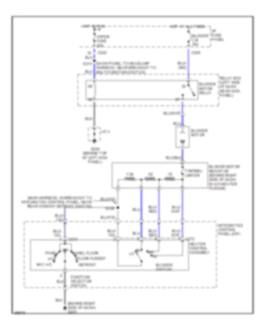
Heater Wiring Diagram for Ford Escort ZX2 1998
List of elements for Heater Wiring Diagram for Ford Escort ZX2 1998:
- (behind right side of dash) g201
- (dash panel to headlamp s213
- (main harness, in breakout to integrated control panel, near rear window defrost switch)
- .33 ohms
- .62 ohms
- 1.38 ohms
- A/c
- Blower c.b. 30a
- Blower motor
- Blower motor relay
- Blower motor resistor (behind right side of dash, in a/c-heater plenum)
- Blower switch
- C200
- C220
- C272
- C273
- Defrost
- Floor flr/def
- Function selector switch
- G200 (behind top of left kick panel)
- Harness, near breakout to multi-function switch)
- Heater control assembly
- Hot at all times
- Hot in run
- I/p fuse panel
- Integrated control panel (icp)
- J/c 3
- Max a/c
- Off
- Panel
- Panel floor
- Relay box (left side of dash, near kick panel)
- S238
- Thermal limiter
- Wiper fuse 20a
 Čeština
 Dansk
Dansk Deutsch
 Ελληνικά
 English
 English
 Español
 Suomi
Suomi Français
 Français
 עברית
עברית Hrvatski
 Magyar
 Italiano
 日本語
日本語 한국어
한국어 Nederlands
 Polski
 Português
 Română
 Русский
 Slovenčina
 Slovenščina
 Svenska
 Türkçe
 中文 (中国)
 Português