CRUISE CONTROL
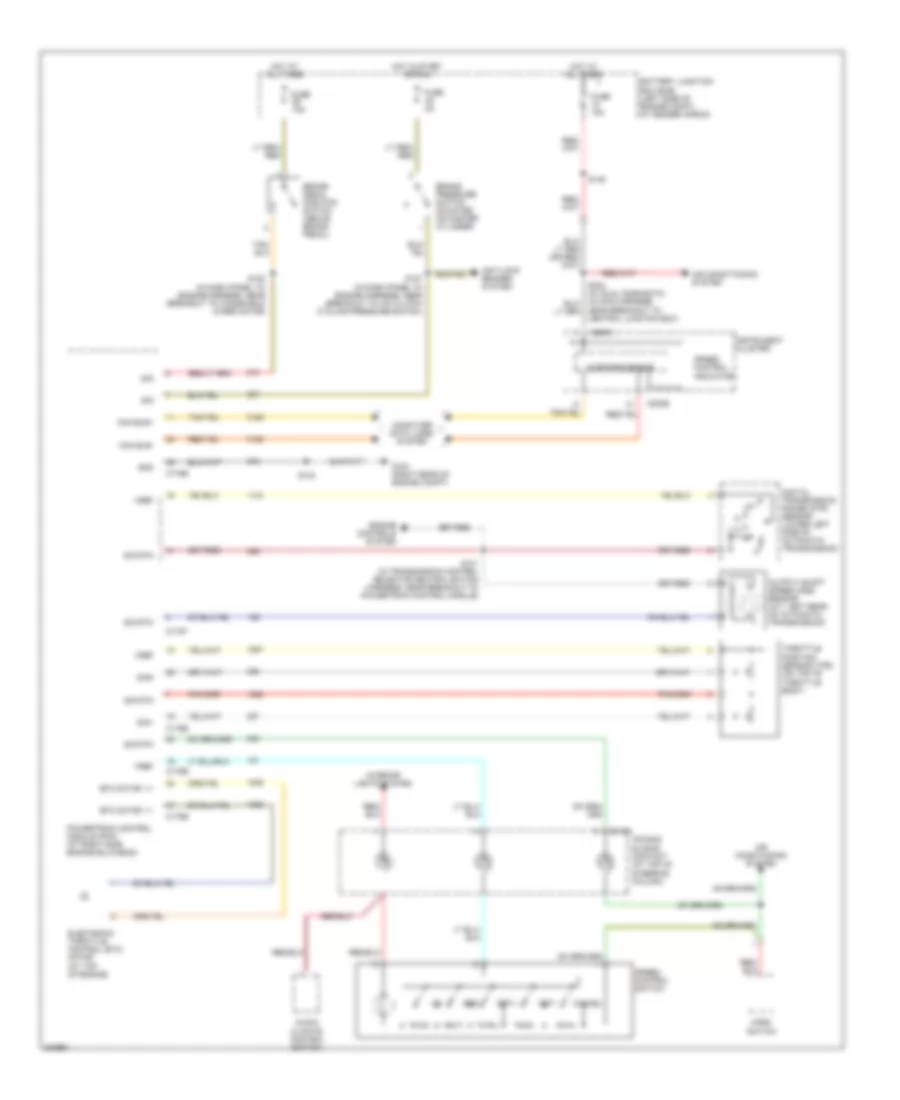
Cruise Control Wiring Diagram, with IVD for Ford Explorer 2005
 https://portal-diagnostov.com/license.html
Automotive Electricians Portal FZCO
Automotive Electricians Portal FZCO
https://portal-diagnostov.com/license.html
https://portal-diagnostov.com/license.html
Automotive Electricians Portal FZCO
Automotive Electricians Portal FZCO
List of elements for Cruise Control Wiring Diagram, with IVD for Ford Explorer 2005:
- Air bag sliding contact (at top of steering column)
- Air conditioning system
- Audio/ climate control switch
- Battery junction box (bjb) (left side of engine compt, at fender apron)
- Brake pedal position switch (above brake pedal)
- C175b
- C175e
- C175t
- C218a
- C220a
- C220b
- Can bus+
- Can bus-
- Cancel
- Computer data lines system
- Digital transmission range (dtr) sensor (lower left side of automatic transmission)
- Electronic throttle control (etc) motor (at top of engine)
- Engine controls system
- Etc motor, +/-
- Fuse 15a
- G104 (right rear of engine compt)
- Gnd
- Horn switch
- Hot at all times
- Instrument cluster
- Interior lights system
- Microprocessor
- Near breakout to central junction box)
- Output shaft speed (oss) sensor (a/t: left rear of automatic transmission)
- Powertrain control module (pcm) (at right side engine bulkhead)
- Redundant pedal switch (under left side dash panel)
- Res
- S101 (in transmission control selector neutral switch harness, near breakout to powertrain control module)
- S120 (in dash panel to engine harness, near breakout to left horn)
- S132
- S149
- S171
- S173
- Set+
- Set-
- Sig
- Sig rtn
- Sig1
- Sig2
- Speed control indicator
- Speed control switch
- Throttle position sensor (tps) (on top of throttle body)
- Vref
Cruise Control Wiring Diagram, without IVD for Ford Explorer 2005
List of elements for Cruise Control Wiring Diagram, without IVD for Ford Explorer 2005:
- Air bag sliding contact (at top of steering column)
- Air conditioning system
- Anti-lock brakes system
- Audio/ climate control switch
- Battery junction box (bjb) (left side of engine compt, at fender apron)
- Brake pedal position switch (above brake pedal)
- Brake pressure switch (mounted on master cylinder)
- C175b
- C175e
- C175t
- C218a
- C220a
- C220b
- Can bus+
- Can bus-
- Cancel
- Computer data lines system
- Digital transmission range (dtr) sensor (lower left side of automatic transmission)
- Electronic throttle control (etc) motor (at top of engine)
- Engine controls system
- Etc motor, +/-
- Fuse 15a
- Fuse 2a
- G104 (right rear of engine compt)
- Gnd
- Horn switch
- Hot at all times
- Hot in start or run
- Instrument cluster
- Interior lights system
- Microprocessor
- Near breakout to central junction box)
- Output shaft speed (oss) sensor (a/t: left rear of automatic transmission)
- Powertrain control module (pcm) (at right side engine bulkhead)
- Res
- S101 (in transmission control selector neutral switch harness, near breakout to powertrain control module)
- S120 (in dash panel to engine harness, near breakout to windshield wiper motor)
- S127 (in dash panel to engine harness, near breakout to a/c clutch cycling pressure switch)
- S132
- S149
- Set+
- Set-
- Sig
- Sig rtn
- Sig1
- Sig2
- Speed control indicator
- Speed control switch
- Throttle position sensor (tps) (on top of throttle body)
- Vref

 Čeština
 Dansk
Dansk Deutsch
 Ελληνικά
 English
 English
 Español
 Suomi
Suomi Français
 Français
 עברית
עברית Hrvatski
 Magyar
 Italiano
 日本語
日本語 한국어
한국어 Nederlands
 Polski
 Português
 Română
 Русский
 Slovenčina
 Slovenščina
 Svenska
 Türkçe
 中文 (中国)