SHIFT INTERLOCK
Shift Interlock Wiring Diagram for Ford Explorer 2005
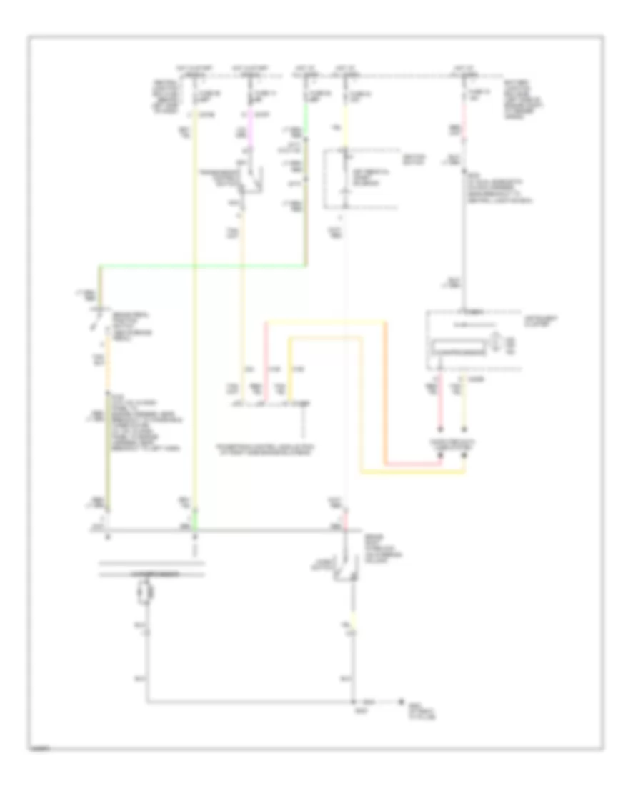
List of elements for Shift Interlock Wiring Diagram for Ford Explorer 2005:
- (on steering column)
- All times
- Battery junction box (bjb) (left side of engine compt, at fender apron)
- Brake pedal position switch (above brake pedal)
- Brake shift interlock
- C175b
- C220a
- C220b
- C270e
- C270f
- Central junction box (cjb) (behind left side of dash)
- Computer data lines system
- Fuse 13 5a
- Fuse 15 15a
- Fuse 23 30a
- Fuse 25 15a
- Fuse 26 7.5a
- G200 (at right "a" pillar)
- Hot at
- Hot in start
- Ignition switch
- Instrument cluster
- Key removal inhibit solenoid
- Micro switch
- Microprocessor
- Nca
- O/d off ind
- Or run
- Powertrain control module (pcm) (at right side engine bulkhead)
- Red
- S120 (w/o ivd: in dash panel to engine harness, near breakout to windshield wiper motor) (w/ ivd: in dash panel to engine harness, near breakout to left horn)
- S171 (w/o ivd)
- S173
- S223
- S232 (w/ dual zone eatc) (in main harness, near breakout to central junction box)
- Transmission control switch
 Čeština
 Dansk
Dansk Deutsch
 Ελληνικά
 English
 English
 Español
 Suomi
Suomi Français
 Français
 עברית
עברית Hrvatski
 Magyar
 Italiano
 日本語
日本語 한국어
한국어 Nederlands
 Polski
 Português
 Română
 Русский
 Slovenčina
 Slovenščina
 Svenska
 Türkçe
 中文 (中国)
 Português