TRANSMISSION
4WD Wiring Diagram for Ford Explorer 2005
 https://portal-diagnostov.com/license.html
Automotive Electricians Portal FZCO
Automotive Electricians Portal FZCO
https://portal-diagnostov.com/license.html
https://portal-diagnostov.com/license.html
Automotive Electricians Portal FZCO
Automotive Electricians Portal FZCO
List of elements for 4WD Wiring Diagram for Ford Explorer 2005:
- (in dash panel to engine harness, near breakout to right side of engine compt)
- (main harness, near breakout to c2126) s263
- 87a
- Battery junction (bjb) box (left side of engine compt, at fender apron)
- Brake pedal position switch (above brake pedal)
- Brk ped pos sw
- C175b
- C175t
- C270f
- Central junction box (cjb) (behind left side of dash)
- Cltch coil pwr
- Cltch coil rtn
- Computer data lines system
- Digital transmission range (dtr) sensor (lower left side of automatic transmission)
- Engine compartment relay box (right side of engine compt)
- Four-wheel drive switch
- Fuse 15a
- Fuse 20a
- Fuse 30a
- Fuse 5a
- G102 (left front of engine compartment)
- G103 (right front of engine compt)
- High
- Hot at all times
- Hot in run or start
- Illum
- Ind cntrl
- Interior lights system
- Low
- Magnetic clutch coil
- N tow sw
- Nca
- Neutral sw
- Neutral tow indicator
- Off
- Other
- Position 1
- Position 2
- Position 3
- Position 4
- Position ind
- Position sw rtn
- Powertrain control module (pcm) (at right side engine bulkhead)
- S114
- S116
- S119
- S120 (w/ivd: in dash panel to engine harness, near breakout to left horn) (w/o ivd: in dash panel to engine harness, near breakout to windshield wiper motor)
- S149
- Sig rtn
- To engine harness, near breakout to g100)
- Transfer case assembly controls (on left side of transfer case)
- Transfer case high to low relay
- Transfer case low to high relay
- Trns shft mot
- Vbatt
- Vref
- W/ 1 speed
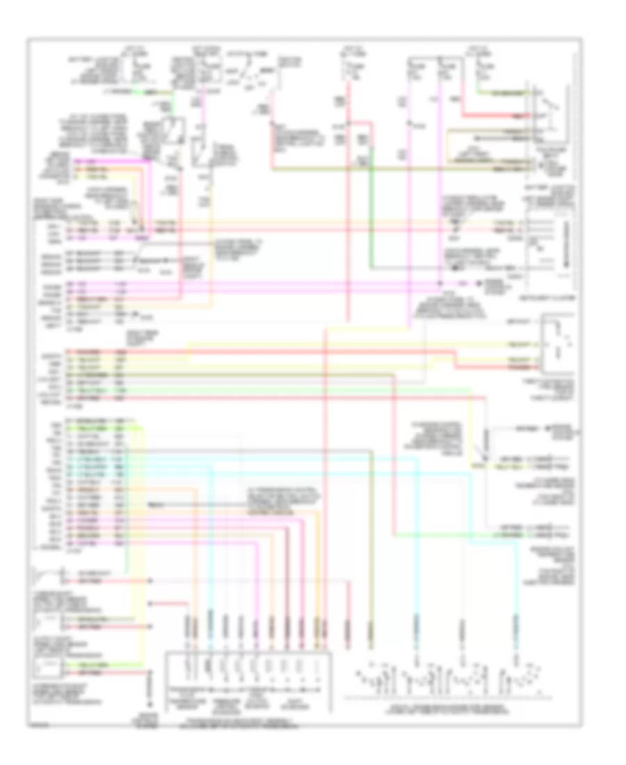
A/T Wiring Diagram for Ford Explorer 2005
List of elements for A/T Wiring Diagram for Ford Explorer 2005:
- (4.0l)
- (4.6l)
- (behind left side of dash) data link connector
- (dlc)
- (in dash panel to engine harness, near breakout to a/c clutch cycling pressure switch)
- (in dash panel to engine harness, near breakout to c1168)
- (in engine control sensor & fuel charge harness, near breakout to powertrain control module)
- (in transmission control selector neutral switch harness, near breakout to powertrain control module)
- (main harness, near breakout central to junction box)
- (main harness, near breakout to left side of dash)
- (right rear of engine compt)
- (right side engine bulkhead) powertrain control module (pcm)
- (w/ ivd: in dash panel to engine harness, near breakout to left horn) (w/o ivd: in dash panel to engine harness, near breakout to windshield wiper motor)
- (window regulator jumper harness, near breakout for center of dash)
- Acc
- Battery junction (bjb) box (left engine compt, at fender apron)
- Battery junction (bjb) box (left side of engine compt, at fender apron)
- Brake in
- Brake pedal position switch (above brake pedal)
- C175b
- C175e
- C175t
- C220a
- C220b
- C270f
- Can +
- Can -
- Central junction box (cjb) (behind left side of dash)
- Cht
- Cylinder head temperature sensor (4.6l) (top front of cylinder head)
- Digital transmission range (dtr) sensor (lower left side of automatic transmission)
- Ect
- Engine controls system
- Engine coolant temperature sensor (4.0l) (top right of engine, near injector harness)
- Feps
- Fuse 15a
- Fuse 40a
- Fuse 5a
- G101 (left front engine compt)
- G104
- G105
- Ground
- Hot at all times
- Hot in run or start
- Ignition switch
- Instrument cluster
- Intermediate shaft speed (iss) sensor (top left side of automatic transmission)
- Iss
- Lock
- Microprocessor
- Nca
- O/d off
- Off
- Oss
- Output shaft speed (oss) sensor (left rear of automatic transmission)
- Pcm power diode
- Pcm power relay
- Pcs a
- Pcs b
- Pcs c
- Power
- Pressure control solenoids
- Red
- Return
- S101
- S102
- S120
- S130
- S132
- S148
- S149
- S173
- S207 (in main harness, near breakout to central junction box)
- S209
- S212
- S232
- S301
- S304
- Shift solenoids
- Sig 1
- Sig 2
- Sig rtn
- Ss a
- Ss b
- Ss c
- Ss d
- Start
- Tcc sol
- Tcs
- Tft
- Throttle position (tps) sensor (top of throttle body)
- Torque conv clutch solenoid
- Tr1
- Tr2
- Tr3a
- Tr4
- Trans- mission control switch
- Transmission fluid temperature sensor
- Transmission solenoid body assembly (on lower left of automatic transmission)
- Tss
- Turbine shaft speed (tss) sensor (on top left side of automatic transmission)
- Vbatt
- Vref
 Čeština
 Dansk
Dansk Deutsch
 Ελληνικά
 English
 English
 Español
 Suomi
Suomi Français
 Français
 עברית
עברית Hrvatski
 Magyar
 Italiano
 日本語
日本語 한국어
한국어 Nederlands
 Polski
 Português
 Română
 Русский
 Slovenčina
 Slovenščina
 Svenska
 Türkçe
 中文 (中国)
 Português