ENGINE PERFORMANCE
3.5L
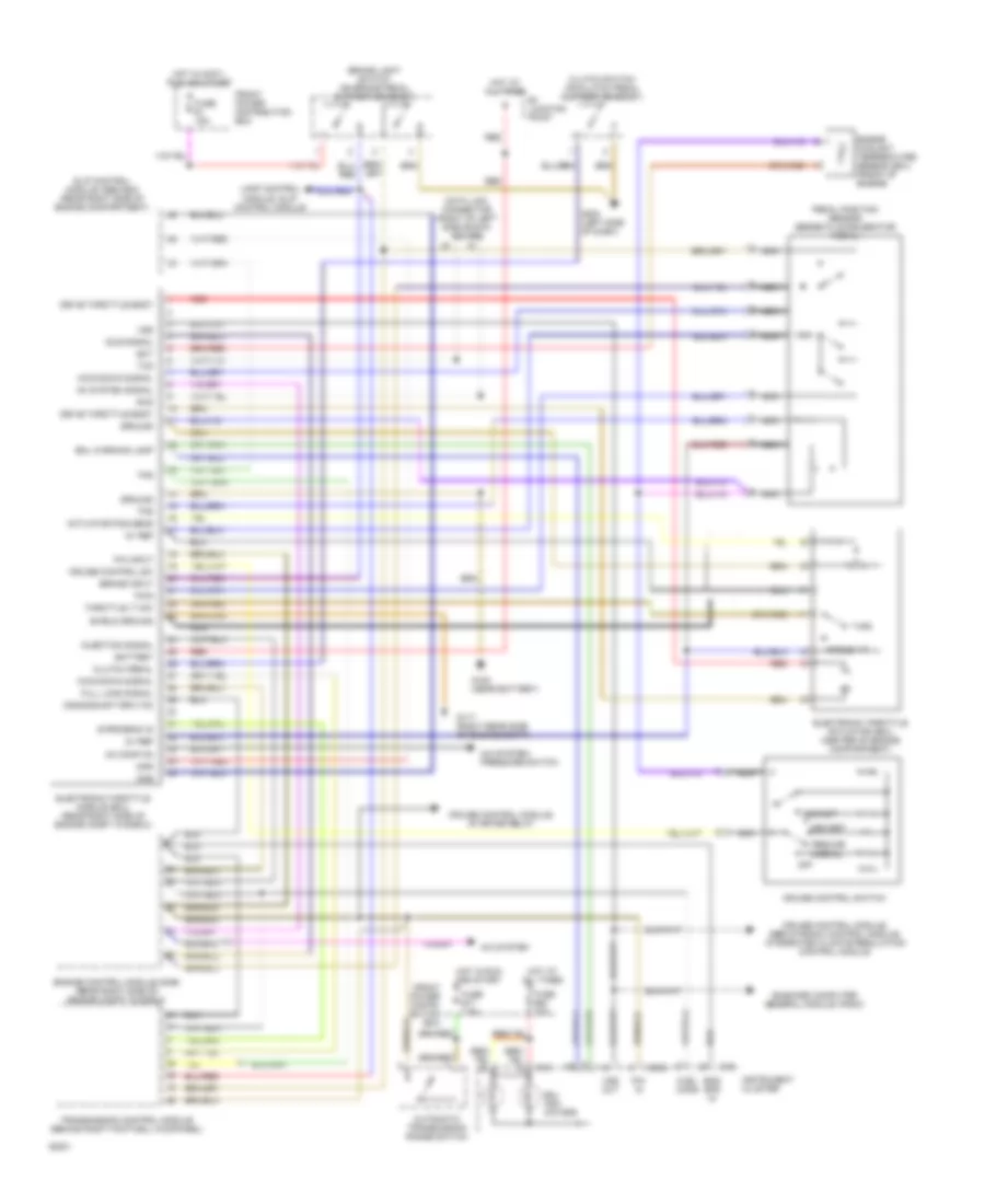
3.5L, Electronic Throttle Control Wiring Diagram for BMW 535i 1993
List of elements for 3.5L, Electronic Throttle Control Wiring Diagram for BMW 535i 1993:
- 5v ref
- A/c system
- A/c system: pressure switch
- Ac comp on
- Ac system signal
- Acc/set
- Actuator pos sens
- Angle >17
- Automatic transmission range switch
- B+ juncton point
- Battery
- Brake input
- Brake light switch (on brake pedal support bracket)
- Clutch pedal
- Clutch switch (on clutch pedal support bracket)
- Crankshaft rpm (td)
- Cruise control module, servotronic control module, integrated climate regulation control module
- Cruise control module, starter relay
- Cruise control sw
- Cruise control switch
- Data link connector (right of left side shock tower)
- Dec/set
- Dke
- Dkr
- Drive throttle body
- Ect
- Electronic throttle actuator (eml) (center of engine compartment)
- Electronic throttle module (eml) (rear right side of engine compt in e-box)
- Eml indi- cators
- Eml warning lamp
- Eng spd in
- Engine control module (dme) (rear right side of engine compt in e-box)
- Engine coolant temperature sensor (eml) (front of engine)
- Front power distri- bution box
- Front power distribution box
- Fuel cons
- Full load signal
- Fuse #1 15a
- Fuse #17 7.5a
- Fuse #20 10a
- G117 (right rear side of engine compt)
- G120 (near battery)
- G202 (left side of dash)
- Ground
- Hot at all times
- Hot in accy, run and start
- Hot in run and start
- Idle signal
- Injection signal
- Instrument cluster
- Kick-down signal
- Lamp control module, slip control module
- Nca
- Normal
- Off
- On-board computer general module, radio
- P/n in
- P/n input
- Pedal position sensor (beneath accelerator pedal)
- Pwg
- Red
- Resume
- Rxd
- S-program id
- Shield ground
- Slip control module (abs/asc) (rear right side of engine compartment)
- Throttle 17 sw
- Tps
- Transmission control module (behind right footwell kickpanel)
- Txd
- Vss
- Vss out
- X16
- X502
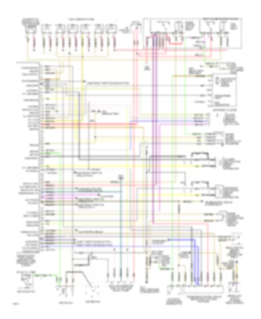
3.5L, Engine Performance Wiring Diagrams, with Electronic Throttle System for BMW 535i 1993
List of elements for 3.5L, Engine Performance Wiring Diagrams, with Electronic Throttle System for BMW 535i 1993:
- (not used)
- 15a
- 7.5a
- 87a
- A/c system
- Acc
- Automatic transmission range switch
- Aux fan sig
- Battery
- Brake light switch (on brake pedal support)
- Check control module
- Crank rpm
- Crankshaft position/rpm sensor (near distributor)
- Cruise control module, starter relay
- Cyl iden sens
- Cylinder identification sensor (near distributor)
- Data link connector (right of left side shock tower)
- Distributor
- Drive away sig
- Ecm rly ctrl
- Elect throttle module, pin 28
- Elect throttle module, pin 4
- Electronic throttle module, pin 18
- Electronic throttle module, pin 24
- Electronic throttle module, pin 29
- Electronic throttle module, pin 8
- Eng iat sens
- Engine control module (dme) (rear right side of engine compt in e-box)
- Engine control module relay
- Engine intake air temperature sensor (front of engine)
- Engine speed input
- Evap emission
- Evaporative emission valve (left rear side of engine)
- Front power distri- bution box
- Front power distribution box
- Fuel consumption
- Fuel injector valves
- Fuel pump (right side of luggage comp)
- Fuel pump relay
- Fuel pump rly
- Fuse
- Fuse 23
- G117 (right rear side of engine compt)
- G120 (near battery)
- G120 (right side of engine compt)
- G303 (below right rear seat)
- Ground
- Heated oxygen sensor (on catalytic converter)
- Ho2s ground
- Ho2s signal
- Hot at all times
- Hot in run or start
- Iat signal
- Idle signal
- Ign timing
- Ignition
- Ignition coil
- Ignition switch
- Inj 1,3 & 5
- Inj 2,4 & 6
- Instrument cluster
- Junction
- Kva signal
- Malfunction indicator (check engine)
- Mil indicator
- Nca
- Off
- On-board computer, slip control module
- P/n input
- Pedal position sensor (beneath accelerator pedal)
- Point
- Programming vol
- Red
- Run
- Rxd data link
- Slip control module
- Start
- Tcc wk signal
- Timing control
- Torque cutout
- Transmission control module (behind right footwell kickpanel)
- Transmission valve unit
- Txd data link
- Vaf sens
- Vaf signal
- Volume air flow sensor (ahead of oil fill cap)
- Wot signal
- X16
- X502
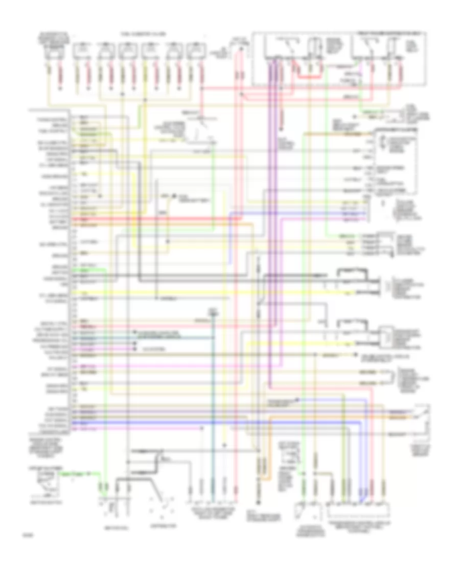
3.5L, Engine Performance Wiring Diagrams, without Electronic Throttle System for BMW 535i 1993
List of elements for 3.5L, Engine Performance Wiring Diagrams, without Electronic Throttle System for BMW 535i 1993:
- (not used)
- 15a
- 7.5a
- 87a
- A/c press sig
- A/c system
- Acc
- Automatic transmission range switch
- Aux fan sig
- Battery
- Crank rpm
- Crankshaft position/rpm sensor (near distributor)
- Cruise control module, starter relay
- Cyl iden sens
- Cylinder identification sensor (near distributor)
- Data link connector (right of left side shock tower)
- Distributor
- Drive away sig
- Ecm rly ctrl
- Eng iat sens
- Engine control module (dme) (rear right side of engine compt in e-box)
- Engine control module relay
- Engine coolant temperature sensor (front of engine)
- Engine speed input
- Evap emission
- Evaporative emission valve (left rear side of engine)
- Front power distri- bution box
- Front power distribution box
- Fuel consumption
- Fuel injector valves
- Fuel pump (right side of luggage comp)
- Fuel pump relay
- Fuel pump rly
- Fuse
- Fuse 23
- G117 (right rear side of engine compt)
- G120 (near battery)
- G303 (below right rear seat)
- Ground
- Heated oxygen sensor (on catalytic converter)
- Ho2s ground
- Ho2s signal
- Hot at all times
- Hot in run or start
- Iat signal
- Idle signal
- Idle speed control valve (on coolant inlet)
- Ign timing
- Ignition
- Ignition coil
- Ignition switch
- Inj 1,3 & 5
- Inj 2,4 & 6
- Instrument cluster
- Isc close ctrl
- Isc open ctrl
- Junction
- Kva signal
- Malfunction indicator (check engine)
- Mil indicator
- Nca
- Off
- On-board computer, slip control module
- P/n input
- Point
- Programming vol
- Red
- Run
- Rxd data link
- Slip control module
- Start
- Tcc wk signal
- Throttle position sensor
- Timing control
- Transmission control module (behind right footwell kickpanel)
- Transmission valve unit
- Txd data link
- Vaf sens
- Vaf signal
- Vehicle speed output
- Volume air flow sensor (ahead of oil fill cap)
- Vss
- Wot signal
- X16
- X502

 Čeština
 Dansk
Dansk Deutsch
 Ελληνικά
 English
 English
 Español
 Suomi
Suomi Français
 Français
 עברית
עברית Hrvatski
 Magyar
 Italiano
 日本語
日本語 한국어
한국어 Nederlands
 Polski
 Português
 Română
 Русский
 Slovenčina
 Slovenščina
 Svenska
 Türkçe
 中文 (中国)