BODY CONTROL MODULES
Body Control Modules Wiring Diagram for Nissan Maxima GXE 2003
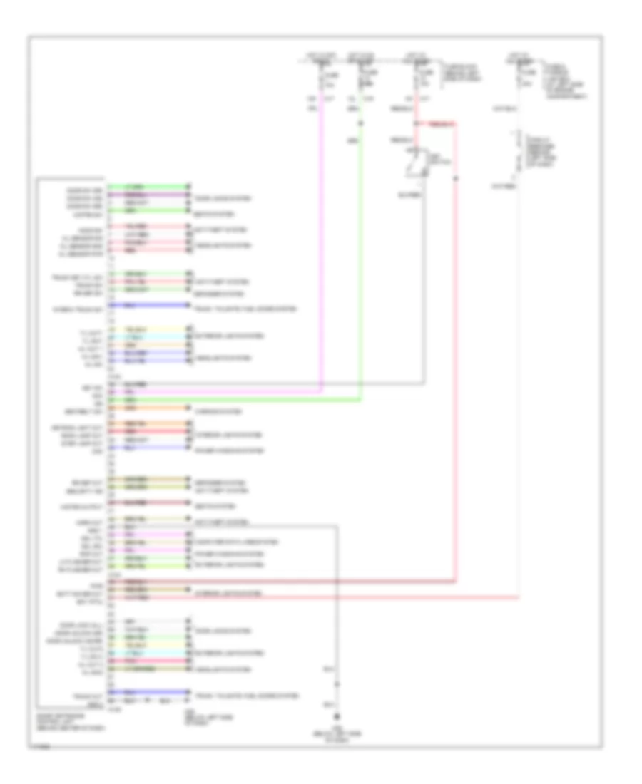
List of elements for Body Control Modules Wiring Diagram for Nissan Maxima GXE 2003:
- 12k
- 12l
- A/l sensor gnd
- A/l sensor pwr
- A/l sensor sig
- A/l sw
- Acc
- Anti-theft system
- Bat (ptc)
- Batt saver out
- Circuit breaker (behind left side of dash)
- Com
- Computer data lines system
- Ddl (rx)
- Ddl (tx)
- Defogger system
- Door lock (all)
- Door locks system
- Door sw (as)
- Door sw (dr)
- Door sw (rr)
- Door unlock (as,rr)
- Door unlock (dr)
- Exterior lights system
- Fuse & fusible link box (at left side of engine compartment)
- Fuse 10a
- Fuse block (behind left side of dash)
- Fuse i 40a
- Gnd 1
- Gnd 2
- H/l out 1
- H/l out 2
- H/l sw1
- H/l sw2
- H/strg output
- H/strg sw
- Headlights system
- Hood sw
- Horn out
- Hot at all times
- Hot in acc or on
- Hot in on or start
- Ign
- Interia trunk sw
- Interior lights system
- Key sw
- Key switch
- Keyring light out
- Lh flasher out
- M143
- M144
- M145
- M17
- M19
- M25 (below left side of dash)
- Pnk
- Power windows system
- Pwr
- Rap out
- Red
- Rh flasher out
- Room lamp out
- Rr def out
- Rr def sw
- Seatbelt sw
- Seats system
- Security ind
- Smart entrance control unit (behind center of dash)
- Step lamp out
- T/l out1
- T/l out2
- T/l sw 2
- T/l sw1
- Trunk key cyl sw
- Trunk out
- Trunk sw
- Trunk, tailgate, fuel doors system
- Warning system
 Čeština
 Dansk
Dansk Deutsch
 Ελληνικά
 English
 English
 Español
 Suomi
Suomi Français
 Français
 עברית
עברית Hrvatski
 Magyar
 Italiano
 日本語
日本語 한국어
한국어 Nederlands
 Polski
 Português
 Română
 Русский
 Slovenčina
 Slovenščina
 Svenska
 Türkçe
 中文 (中国)
 Português