POWER DISTRIBUTION
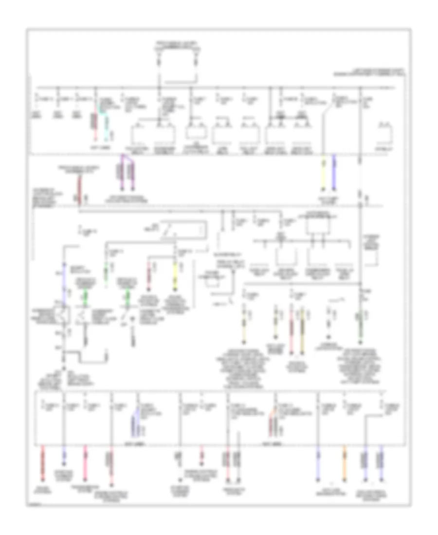
Power Distribution Wiring Diagram (1 of 2) for Mitsubishi Lancer GT 2012
 https://portal-diagnostov.com/license.html
Automotive Electricians Portal FZCO
Automotive Electricians Portal FZCO
https://portal-diagnostov.com/license.html
https://portal-diagnostov.com/license.html
Automotive Electricians Portal FZCO
Automotive Electricians Portal FZCO
List of elements for Power Distribution Wiring Diagram (1 of 2) for Mitsubishi Lancer GT 2012:
- (2.0l (turbo))
- (evolution)
- (except 2.0l (turbo))
- (except evolution)
- (not used)
- Acc
- Acc relay 3
- Anti-lock brakes system
- Anti-lock brakes, engine controls, cruise control, shift interlock, exterior lights & transmissions systems
- Battery
- C-129
- C-132
- C-304
- C-308
- C-309
- C-313
- C-315
- C-316
- C-317
- Computer data lines system
- Defogger system
- Electronic power steering system
- Engine controls system
- Etacs-ecu (on rear of junction block, behind left end of dash)
- Except evolution
- From etacs-ecu (diagram 1 of 2)
- Fuel pump relay (2.0l & 2.4l) fuel pump relay 2 (2.0l (turbo))
- Fuse 10 15a
- Fuse 12 7.5a
- Fuse 14 10a
- Fuse 15 20a
- Fuse 17 10a
- Fuse 18 7.5a
- Fuse 2 15a
- Fuse 21 30a
- Fuse 22 7.5a
- Fuse 23
- Fuse 24
- Fuse 25 30a
- Fuse 5 10a
- Fusible link 20 30a
- Fusible link 33 140a 120a
- Fusible link 34 80a
- Fusible link 35 80a
- Fusible link 36 120a
- Fusible link 37 80a
- Fusible link box (next to battery)
- Headlight backup circuit
- Ig1 relay
- Ignition control circuit
- Ignition switch
- Lock
- Power tops system
- Power window relay
- Power windows system
- Red
- Relay box (passenger compartment)
- Seats system
- Start
- Starting/ charging system
- To engine compartment fuse/relay box (diagram 2 of 2)
- To etacs-ecu (diagram 2 of 2)
- To ignition switch (diagram 1 of 2)
- To power window relay (diagram 2 of 2)
- Turn-signal light control circuit
Power Distribution Wiring Diagram (2 of 2) for Mitsubishi Lancer GT 2012
List of elements for Power Distribution Wiring Diagram (2 of 2) for Mitsubishi Lancer GT 2012:
- (+)
- (-)
- (hatchback) liftgate open relay
- (left side of engine compt) engine compartment fuse/relay box
- (not used)
- (on rear of junction block, behind left end of dash) etacs-ecu
- A-14x
- A-16x
- A-20x
- A/c compressor clutch relay
- Acc relay 2
- Accessory socket (front floor console)
- Accessory socket (rear floor (-) console)
- Air conditioning & cooling fans systems
- Air conditioning, anti-lock brakes, sound, cruise control, interior lights, transmissions, seats, instrument cluster, exterior lights, navigation & anti-theft systems
- Air conditioning, warning, door locks, headlights, interior lights, anti-theft, navigation, instrument cluster, power windows, sound, wiper/washer, exterior lights & trunk, tailgate, fuel doors systems
- Anti-lock brakes system
- Anti-theft system
- Blower relay
- C-26
- C-307
- C-309
- C-311
- C-313
- C-315
- C-317
- Cigarette lighter (front floor console)
- Condenser fan relay
- Cooling fans & air conditioning systems
- Door lock relay
- Driver's door unlock relay
- Engine controls & cruise control systems
- Except evolution
- Fan control relay
- Fog light relay
- From fusible link box (diagram 1 of 2)
- From ig1 relay (diagram 1 of 2)
- Fuse 1 15a
- Fuse 1 30a
- Fuse 10
- Fuse 11
- Fuse 12
- Fuse 13 (w/ discharge type headlights) 10a
- Fuse 13 (w/ halogen type headlights) 10a
- Fuse 13 15a
- Fuse 15a
- Fuse 16 10a
- Fuse 19 15a
- Fuse 2 7.5a
- Fuse 25
- Fuse 3 10a
- Fuse 3 20a
- Fuse 30a
- Fuse 31 30a
- Fuse 4 10a
- Fuse 5 7.5a
- Fuse 6 (evolution)
- Fuse 6 (except evolution) 20a
- Fuse 6 20a
- Fuse 7 10a
- Fuse 7 15a
- Fuse 8 15a
- Fuse 8 7.5a
- Fuse 9 (evolution) 20a
- Fuse 9 (except evolution) 20a
- Fusible link 24 30a
- Fusible link 26 40a
- Fusible link 27 30a
- Fusible link 28 (2.0l turbo) 30a
- Fusible link 28 (except 2.0l turbo) 30a
- Fusible link 29 40a
- G14 (except evolution) (behind left kick panel)
- G18 (evolution) (left front engine compt)
- Headlight relay (high)
- Headlight relay (low)
- Headlights system
- Horn relay
- Interior light control circuit
- Interior lights system
- Mfi relay
- Off
- Passenger's door unlock relay
- Pnk
- Power window relay
- Red
- Sound & navigation systems
- Sound systems
- Sound, navigation, mirrors & transmissions systems
- Starting/ charging system
- Transmissions system
- Trunk lid open relay
- Vehicle w/ accessory socket
- Vehicle w/ cigarette lighter

 Čeština
 Dansk
Dansk Deutsch
 Ελληνικά
 English
 English
 Español
 Suomi
Suomi Français
 Français
 עברית
עברית Hrvatski
 Magyar
 Italiano
 日本語
日本語 한국어
한국어 Nederlands
 Polski
 Português
 Română
 Русский
 Slovenčina
 Slovenščina
 Svenska
 Türkçe
 中文 (中国)