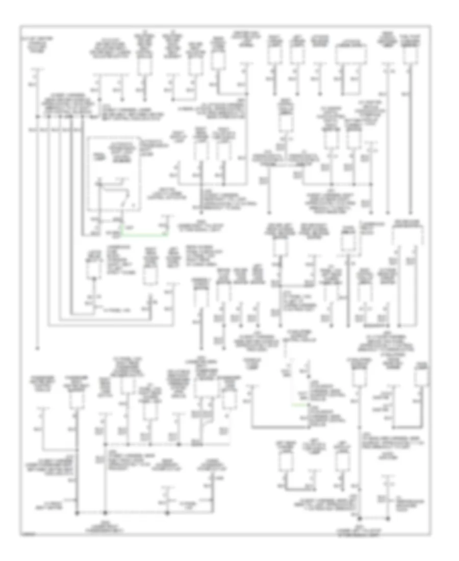
GROUND DISTRIBUTION
Ground Distribution Wiring Diagram (1 of 2) for Chevrolet HHR LS 2008
 https://portal-diagnostov.com/license.html
Automotive Electricians Portal FZCO
Automotive Electricians Portal FZCO
https://portal-diagnostov.com/license.html
https://portal-diagnostov.com/license.html
Automotive Electricians Portal FZCO
Automotive Electricians Portal FZCO
List of elements for Ground Distribution Wiring Diagram (1 of 2) for Chevrolet HHR LS 2008:
- (a/t) park/neutral position (pnp) switch
- (a/t) transmission control module (tcm)
- (behind left end of dash) g201
- (in steering column harness, behind inflatable restraint steering wheel module)
- (under center console, near sdm module)
- (w/ active brake control & power brake system) traction control switch
- (w/ cigarette lighter ashtray) cigar lighter
- (w/o cigarette lighter ashtray) auxiliary power outlet
- 87a
- A/c clutch relay 15
- A/c compressor clutch
- A/c compressor clutch diode
- B x2
- B x3
- Battery
- Battery current sensor
- Body control module (bcm)
- Data link connector (dlc)
- E12 x4
- Electronic brake control module (ebcm)
- Engine control module (ecm)
- Engine cooling fan
- Fog lamp relay 54
- Fog lamp switch
- Fuel pump relay 19
- G103 (left front corner of engine compt)
- G105 (left front of engine block)
- G107 (on front left corner of transmission)
- G108 (right rear of engine block)
- G109 (on left front shock tower)
- G111 (left side of engine compt)
- G203 (behind left end of dash)
- G306
- G403 (right rear corner of vehicle)
- Hazard switch
- Hood ajar switch
- Horn
- Horn switch
- Hvac control assembly
- I/p dimmer switch
- Ignition coil module 1
- Ignition coil module 2
- Ignition coil module 3
- Ignition coil module 4
- Inflatable restraint passenger air bag on/off indicator
- Inflatable restraint sensing & diagnostic module (sdm)
- Inflatable restraint steering wheel module coil
- Instrument panel cluster (ipc)
- J101 (in forward lamp harness, near left front headlamp, approximately 9 cm from breakout to g109)
- J103 (in engine harness, near left rear of engine, approximately 30 cm from breakout to heated oxygen sensor (ho2s) 1)
- J107 (in engine harness, near top of engine, approximately 6 cm from breakout to ignition coil 2 breakout)
- J200 (in i/p harness, near left side of i/p, approximately 29 cm from breakout to g203)
- J201 (in i/p harness, near center console, approximately 18 cm from breakout to inflatable restraint passenger air bag on/off indicator)
- J202
- Left front fog lamp
- Left front marker lamp
- Left headlamp
- Left park/ turn signal lamp
- Left steering wheel controls
- Mass air flow (maf) sensor/ intake air tempe- rature (iat) sensor
- Power steering control module (pscm)
- Radio
- Rear defog relay 14
- Rear washer relay 48
- Rear windshield wiper/washer switch
- Rear wiper relay 17
- Remote control door lock receiver (rcdlr)
- Right front fog lamp
- Right front marker lamp
- Right headlamp
- Right park/ turn signal lamp
- Right steering wheel controls
- Run/ crank relay 51
- Steering wheel control) j208
- Theft deterrent module
- Turn signal/ multi-function switch
- Underhood fuse block (in engine compt, next to left strut tower)
- Washer pump relay 39
- Windshield wiper motor
- Wiper relay 52
- Wiper relay 70
- X1 d3
- X1 k
- X2 f9
- X2 k
- X3 c5
Ground Distribution Wiring Diagram (2 of 2) for Chevrolet HHR LS 2008
List of elements for Ground Distribution Wiring Diagram (2 of 2) for Chevrolet HHR LS 2008:
- (if equipped) driver back heated seat element
- (if equipped) driver heated seat control module
- (if equipped) inside rearview mirror
- (if equipped) sunroof control module
- (if equipped) sunroof switch
- (in body harness, near center console, approximately 29 cm from breakout to a/t shift lock control solenoid) j300
- (w/ 6 way driver power adjuster seat) driver seat lumbar adjuster switch
- (w/ onstar)
- (w/ onstar) vehicle communication interface module (vcim)
- (w/ panel van) left rear access panel lock
- (w/ panel van) right rear access panel lock
- (w/ panel van) right rear passenger access panel release switch
- (w/ s-band digital audio system) digital radio receiver
- (w/o
- A x2
- Assembly window switch
- Audio amplifier
- Automatic transmission shift lever
- Automatic transmission shift lock control solenoid
- Battery current sensor
- Body control module (bcm)
- Brake fluid level switch
- C x406
- Cargo accessory power outlet
- Center high mounted stop lamp (chmsl)
- Chmsl relay
- Console flood lamp
- Dome lamp
- Driver door jamb switch
- Driver door lock switch
- Driver left rear access panel release switch
- Driver right rear access panel release switch
- Driver seat adjuster switch
- Fuel pump & sender assembly
- G301 (under driver's seat)
- G302 (under front passenger's seat)
- G401 (under left tail/stop & turn signal light)
- G402 (under right tail/stop & turn signal light)
- Ignition lock cylinder control actuator
- Inflatable restraint passenger presence system (pps) module
- J301 (in body harness, near center console, approximately 29 cm from s300)
- J303 (in headliner harness, near sunroof, approximately 11 cm from breakout to c397)
- J314 (in seat harness, under driver seat, between heated seat control module & c315)
- J315 (in seat harness, under passenger seat, between heated seat module & c314)
- J400 (in body harness, near right tail lamp, approximately 27 cm from breakout to g402)
- J401 (in body harness, right side of rear compt, approximately 6 cm from breakout to digital radio receiver)
- J402 (in body harness, near left rear tail lamp, approximately 11 cm from g401 breakout)
- J500 (in lf door harness, behind trim panel, approximately 17 cm from breakout to mirror motor)
- J900 (in liftgate harness, in rear liftgate, approximately 16 cm from breakout to rear wiper motor)
- L/gate relse relay 18
- Left back-up lamp
- Left license lamp
- Left rear access panel relay
- Left rear door jamb switch
- Left rear marker lamp
- Left tail/stop & turn signal lamp
- Liftgate door latch
- Liftgate release switch
- Nca
- Onstar)
- Outlet center console auxiliary power
- Outside rearview mirror switch
- Passenger back heated seat element
- Passenger door jamb switch
- Passenger door lock switch
- Passenger heated seat control module
- Prndl lamp
- Rear access panel fuse block (w/ panel van) (right rear of cargo area)
- Rear accessory power outlet
- Rear window defogger grid
- Rear window wiper motor
- Right back-up lamp
- Right front door, approximately 18 cm from s307)
- Right license lamp
- Right rear access panel relay
- Right rear door jamb switch
- Right rear marker lamp
- Right tail/stop & turn signal lamp
- Underhood fuse block (in engine compt, next to left strut tower)
- Underhood relay block
- W/ front seat heater
- W/ panel van
- W/ performance enhanced audio
- W/ s-band digital audio system & onstar
- W/o s-band digital audio system & onstar
- X2 e3
- X307 c

 Čeština
 Dansk
Dansk Deutsch
 Ελληνικά
 English
 English
 Español
 Suomi
Suomi Français
 Français
 עברית
עברית Hrvatski
 Magyar
 Italiano
 日本語
日本語 한국어
한국어 Nederlands
 Polski
 Português
 Română
 Русский
 Slovenčina
 Slovenščina
 Svenska
 Türkçe
 中文 (中国)