AUTOMOTIVE ELECTRICIANS PORTAL

POWER DISTRIBUTION – Chevrolet Silverado 1500 2012 – SYSTEM WIRING DIAGRAMS

POWER DISTRIBUTION

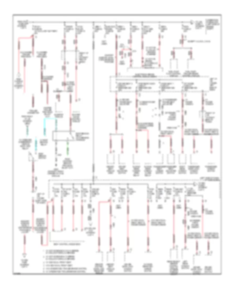
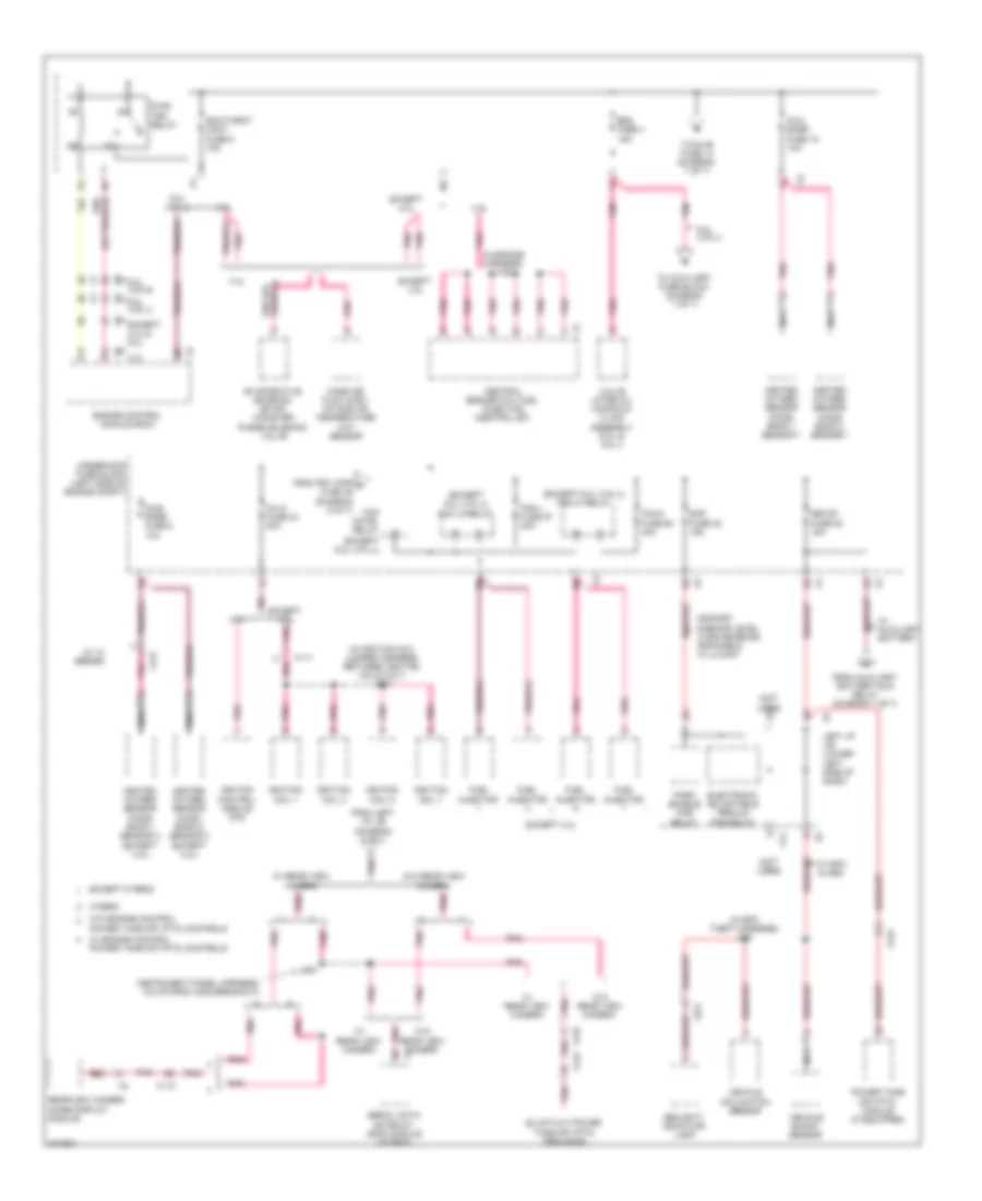
Power Distribution Wiring Diagram (1 of 7) for Chevrolet Silverado 1500 2012

Power Distribution Wiring Diagram (1 of 7) for Chevrolet Silverado 1500 2012 https://portal-diagnostov.com/license.html
https://portal-diagnostov.com/license.html Automotive Electricians Portal FZCO Automotive Electricians Portal FZCO
Download PDF file

List of elements for Power Distribution Wiring Diagram (1 of 7) for Chevrolet Silverado 1500 2012:

  • (in fuse block jumper harness) j210
  • (in fuse block jumper harness) j211
  • (in fuse block jumper harness) j224
  • (in roof console) emergency vehicle roof lamp relay
  • (not used)
  • (on lower left front of engine) (except 4.3l) g102
  • 125a
  • 175a
  • 2b5
  • 4 speed a/t
  • 6 speed a/t
  • 6.0l (vin g)
  • 6.0l (vin j)
  • 60a
  • Automatic a/c
  • Automatic transmission
  • Auxiliary battery relay (if equipped) (rear of engine compt)
  • Auxiliary battery run relay
  • Body builder emergency lamp
  • Body control module (bcm)
  • Dash)
  • Data link connector (dlc)
  • Ecm- batt fuse 12 10a
  • Engine control module (ecm)
  • Evaporative emission (evap) canister vent solenoid valve
  • Except 6.0l (vin j)
  • Fuse a 30a
  • Fuse b 30a
  • Fuse c 30a
  • Fuse d 30a
  • G103 (on front of right cylinder head)
  • G107 (4.3l) (top left rear of engine)
  • G200 (on right front corner of hvac module)
  • Generator
  • Hdlp wash fuse 22 20a
  • Heated seat control module (if equipped)
  • Hvac batt fuse 39 10a
  • Hvac control module
  • I/p 1 accessory power outlet
  • Instrument panel cluster (ipc)
  • Ipc fuse 46 10a
  • Itbc fuse 6 15a
  • J145
  • J200
  • J209 (in fuse block jumper harness)
  • J219
  • Left battery
  • Left i/p j/b (lower left x2 side of dash)
  • Ltr fuse 53 20a
  • Manual a/c
  • Red
  • Relay a
  • Relay b
  • Right battery
  • Right i/p j/b (in right end of x2
  • Seo b2 fuse 37 30a
  • Starter motor
  • Stud 2 fuse 63 30a
  • Tcm-batt fuse 14 15a
  • To auxiliary fuse block (diagram 7 of 7)
  • To left i/p j/b (diagram 4 of 7)
  • To roof beacon switch (diagram 2 of 7)
  • To stud 1 fuse 68 (diagram 2 of 7)
  • To underhood fuse block (diagram 2 of 7)
  • To underhood fuse block (diagram 3 of 7)
  • To underhood fuse block (diagram 6 of 7)
  • Trailer brake control module (if equipped)
  • Trailer brake control relay (if equipped)
  • Transfer case encoder motor
  • Transfer case shift control module
  • Transmission control module (tcm)
  • Trec fuse 67 30a
  • Underhood fuse block (left side of engine compt)
  • Underhood fuse holder (on positive battery terminal)
  • W/ active 2 speed
  • W/ auxiliary battery
  • W/ electronic 2 speed & active 2 speed
  • W/ emergency vehicle roof lamp relay
  • W/ wrecker emergency lamp provisions
  • W/ wrecker relay
  • Wrecker relay
  • Wsw/htr fuse 66 60a
  • X109
  • X116
  • X122
  • X14
  • X205
  • X214
  • X224
  • X228
  • X313
  • X331

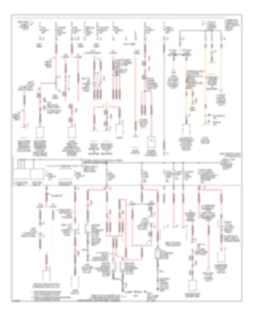
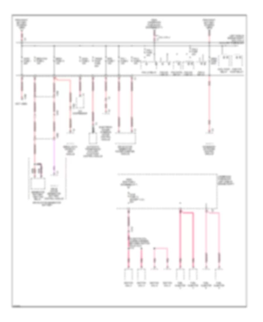
Power Distribution Wiring Diagram (2 of 7) for Chevrolet Silverado 1500 2012

Power Distribution Wiring Diagram (2 of 7) for Chevrolet Silverado 1500 2012 https://portal-diagnostov.com/license.html
https://portal-diagnostov.com/license.html Automotive Electricians Portal FZCO Automotive Electricians Portal FZCO
Obtenha acesso a todos os diagramas de fiação do carroDownload PDF file

List of elements for Power Distribution Wiring Diagram (2 of 7) for Chevrolet Silverado 1500 2012:

  • & vacuum/hydraulic brakes
  • (in camper harness) j414
  • (in sliding rear window jumper harness) j336
  • (left side of dash) i/p fuse block
  • (not used)
  • (w/ individual front seat) j315
  • 2b1
  • 3b4
  • 6.0l (vin j)
  • Abs-1 fuse 61 40a
  • Abs-2 fuse 9 25a
  • Bcm fuse 10a
  • Blower motor control module
  • Body control modue (bcm)
  • Comfort & decor level 3 convenience package
  • Comfort & decor level 3 convenience package & luxury
  • Cooled seats fuse 24 30a
  • Crew cab
  • Ctsy fuse 15a
  • Ddm fuse 4 15a
  • Dim fuse 10a
  • Driver door lock/ window switch
  • Driver seat 2 circuit breaker cb3 25a
  • Driver seat adjuster switch
  • Driver window switch
  • Dsm fuse 10a
  • Elec run board fuse 65 30a
  • Electronic brake control module (ebcm)
  • Except 4.3l/6.0l (vin g)
  • Except comfort & decor level 3 convenience package & luxury
  • Extended cab & power window
  • From fusible link 3 (diagram 1 of 7)
  • From ipc f fuse 46 (diagram 1 of 7)
  • From right i/p j/b (diagram 1 of 7)
  • Fscm fuse 21 20a
  • Fuel pump flow control module
  • Fuel pump/ trailer brake control module
  • G200 (on right front corner of hvac module)
  • Heavy duty abs fuse 59 60a
  • Hvac blwr fuse 70 40a
  • J313
  • J323
  • Lbec 1 fuse 64 60a
  • Left i/p j/b (lower left side of dash)
  • Left i/p j/b (lower left side x1
  • Left rear window switch
  • Lt dr circuit breaker 25a
  • Mbec 1 fuse 69 60a
  • Memory seat module (msm)
  • Obs det fuse 20 10a
  • Of dash)
  • Outside rearview mirror switch
  • Pass seat 1 circuit breaker cb2 25a
  • Passenger door lock/ window switch
  • Passenger seat adjuster switch
  • Passenger seat lumbar switch
  • Passenger window switch
  • Pwr mir fuse 2a
  • Pwr rear wndw circuit breaker cb4 25a
  • Rear hvac fuse 30a
  • Rear object sensor control module (w/ rear parking assist)
  • Rear seat fuse 20a
  • Rear wpr fuse 25a
  • Red
  • Remote control door lock receiver (rcdlr)
  • Right i/p j/b (in right end of dash) x6
  • Right i/p j/b (in right end of x3 dash)
  • Right rear window switch
  • Roof beacon relay (in overhead console)
  • Roof beacon switch
  • Rt doors circuit breaker cb1 25a
  • Rt stop trn fuse 8 15a
  • S/roof fuse 34 30a
  • Sliding rear window close relay
  • Sliding rear window open relay
  • Stud 1 fuse 68 (w/ auxiliary battery) 40a
  • Sunroof module
  • To lgm fuse 71 (diagram 3 of 7)
  • To pdm fuse (diagram 3 of 7)
  • To pdm fuse 9 (diagram 3 of 7)
  • To splice j318 (diagram 4 of 7)
  • Trailer connector
  • Underhood fuse block (left side of engine compt)
  • W/ active & vacuum brake & 10 series
  • W/ active brake
  • W/ active brake & 10 series
  • W/ active brake & w/o 10 series
  • W/ camper trailer provision
  • W/ driver power seat adjuster
  • W/ hydraulic brakes 6.0l (vin j)
  • W/ individual front seat
  • W/ individual front seat & power mirror
  • W/ integrated trailer brake control
  • W/ passenger power seat adjuster
  • W/ power window
  • W/ rear power window
  • W/ roof beacon relay
  • W/ roof mounted light provi- lions
  • W/ sunroof
  • W/ wrecker & emergency vehicle roof lamp relay
  • W/o camper trailer provision
  • W/o individual front seat
  • W/o individual front seat & power mirror
  • W/o integrated trailer brake control
  • X10
  • X11
  • X12
  • X129
  • X303
  • X304
  • X305
  • X313
  • X320
  • X414
  • X700
  • X800

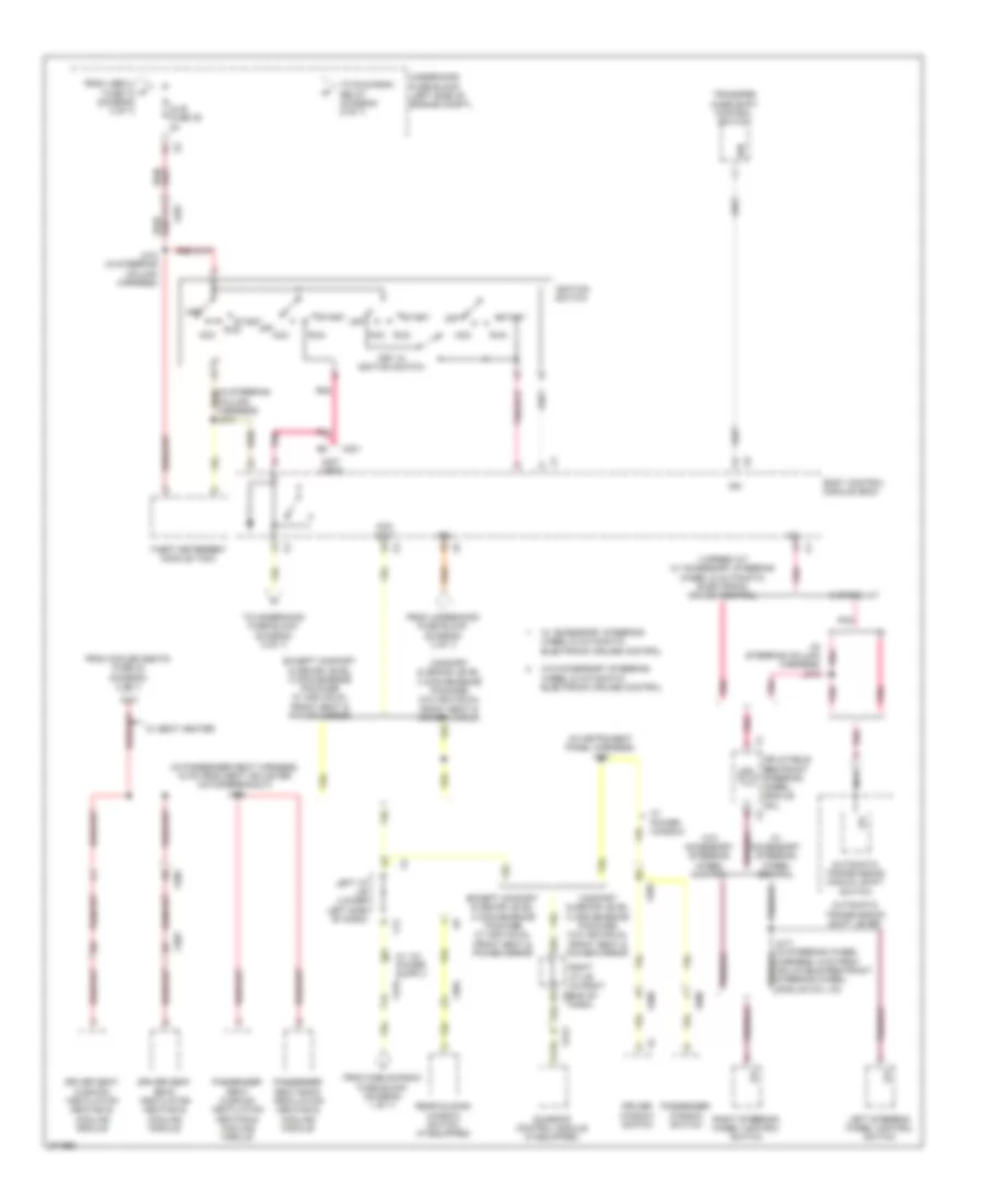
Power Distribution Wiring Diagram (3 of 7) for Chevrolet Silverado 1500 2012

Power Distribution Wiring Diagram (3 of 7) for Chevrolet Silverado 1500 2012 https://portal-diagnostov.com/license.html
https://portal-diagnostov.com/license.html Automotive Electricians Portal FZCO Automotive Electricians Portal FZCO
Obtenha acesso a todos os diagramas de fiação do carroDownload PDF file

List of elements for Power Distribution Wiring Diagram (3 of 7) for Chevrolet Silverado 1500 2012:

  • (in pto jumper harness) (w/ power take off) j127
  • (left side of dash) i/p fuse block
  • (not used)
  • (on right front corner of hvac module) g200
  • 2a1
  • 3b2
  • Air bag batt fuse 45 15a
  • Alc/comp fuse 58 40a
  • Amp fuse 41 30a
  • Audio amplifier (premium performance enhanced audio speaker system)
  • Audio speaker system
  • Automatic a/c
  • Automatic transmission auxiliary fluid pump control module
  • Aux pwr 2 fuse 2 20a
  • Aux pwr fuse 20a
  • Body control module (bcm)
  • Center console accessory power outlet
  • Center seat accessory power outlet (w/ full feature center seat)
  • Chime module
  • Crew cab w/ individual front seat
  • Crew cab/ extended cab w/ performance exhanced audio & front compartment console
  • Dash)
  • Digital radio receiver (if equipped)
  • Esc/alc exh fuse 2 30a
  • From auxiliary battery run relay (diagram 1 of 7)
  • From fscm fuse 21 (diagram 2 of 7)
  • From left i/p j/b (diagram 2 of 7)
  • From lt dr circuit breaker (diagram 2 of 7)
  • G304 (on lower right "b" pillar)
  • Garage door opener (gdo)
  • Hvac control module
  • I/p 2 accessory power outlet
  • Inflatable restraint passenger presence system (pps) module (if equipped)
  • Inflatable restraint sensing & diagnostic module (sdm)
  • Info fuse 22 10a
  • Is lps fuse 10a
  • J203
  • J304
  • Lbec 2 fuse 72 60a
  • Left i/p j/b (lower left side of dash)
  • Left i/p j/b (lower left side x10
  • Lgm fuse 71 30a
  • Lock pcb relay
  • Lock/unlock pcb relay
  • Lt stop trn fuse 6 15a
  • Manual a/c
  • Nca
  • Of dash)
  • Passenger door lock/ window switch
  • Pdm fuse 9 (w/ comfort & decor level 3 convenience package) 15a
  • Performance enhanced
  • Power locks w/o individual front seat & power mirror
  • Power take off (pto) relay
  • Premium performance enhanced
  • Pto fuse 47 15a
  • Radio
  • Rdo fuse 42 15a
  • Rear seat audio (rsa) control (if equipped)
  • Right i/p j/b (in right end of dash)
  • Right i/p j/b (in right end of x3
  • Rse fuse 19 5a
  • Stop lamps fuse 15a
  • To body control module (diagram 4 of 7)
  • To dlis fuse 35 (diagram 4 of 7)
  • Underhood fuse block (left side of engine compt)
  • Unlock pcb relay
  • Vehicle communication interface module (vcim)
  • Video display
  • W/ aux- iliary battery
  • W/ custom front compartment floor console
  • W/ front bench seat
  • W/ individual front seat
  • W/ individual front seat & power mirror
  • W/ luxury
  • W/ rear seat entertain- ment package
  • W/ universal garage door opener
  • W/ wrecker emergency lamp, roof lamp & body builder emergency lamp
  • W/o aux- iliary battery
  • W/o individual front seat
  • W/o luxury
  • W/o luxury & radio
  • W/o radio
  • W/onstar
  • Windshield washer solvent heater (if equipped)
  • X11
  • X123
  • X124
  • X150
  • X212
  • X301
  • X304
  • X305
  • X306
  • X319

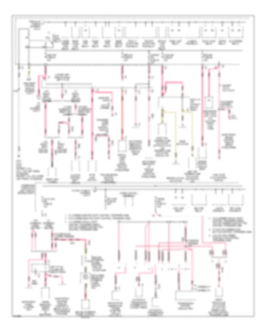
Power Distribution Wiring Diagram (4 of 7) for Chevrolet Silverado 1500 2012

Power Distribution Wiring Diagram (4 of 7) for Chevrolet Silverado 1500 2012 https://portal-diagnostov.com/license.html
https://portal-diagnostov.com/license.html Automotive Electricians Portal FZCO Automotive Electricians Portal FZCO
Obtenha acesso a todos os diagramas de fiação do carroDownload PDF file

List of elements for Power Distribution Wiring Diagram (4 of 7) for Chevrolet Silverado 1500 2012:

  • (in instrument panel harness) j231
  • (in passenger seat harness, 15 cm from seat adjuster motor breakout) j318
  • (in steering column harness) j216
  • (not used)
  • 12v
  • 2b3
  • 4 speed a/t w/ accessory steering wheel & automatic electronic cruise control
  • 6 speed a/t
  • Acc
  • Acc volt
  • Automatic transmission manual shift switch
  • Automatic transmission shift lever
  • Body control module (bcm)
  • Column harness) j213
  • Comfort & decor level 3 convenience package w/o individual front seat & power mirror
  • Dash)
  • Dlis fuse 35 2a
  • Driver seat back ventilation heating & cooling module
  • Driver seat cushion ventilation heating & cooling module
  • Driver window switch
  • Except comfort & decor level 3 convenience package w/ individual front seat & power mirror
  • From cooled seats fuse 24 (diagram 2 of 7)
  • From lbec 2 fuse 72 (diagram 3 of 7)
  • From mobile radio fuse block (diagram 1 of 7)
  • From underhood fuse block (diagram 3 of 7)
  • Ign
  • Ignition switch
  • Inflatable restraint steering wheel module coil
  • J212 (in steering column harness)
  • Key in ignition switch
  • Left i/p j/b (lower left side of dash)
  • Left steering wheel control switch
  • Nca
  • Off
  • Passenger seat back ventilation heating & cooling module
  • Passenger seat cushion ventilation heating & cooling module
  • Passenger window switch
  • Pnk
  • Rear sliding window switch (if equipped)
  • Right i/p j/b (in right end of x2
  • Right steering wheel control switch
  • Run
  • Start
  • Sunroof control module (if equipped)
  • Theft deterrent module (tdm)
  • To run/crnk relay (diagram 5 of 7)
  • To underhood fuse block (diagram 5 of 7)
  • Transfer case shift control switch
  • Underhood fuse block (left side of engine compt)
  • W/ accessory steering wheel & automatic electronic cruise control
  • W/ accessory steering wheel control
  • W/ power window
  • W/ seat heater
  • W/o accessory steering wheel & automatic electronic cruise control
  • W/o accessory steering wheel control
  • X14
  • X201
  • X202
  • X219
  • X303
  • X304
  • X305
  • X313
  • X500
  • X600

Power Distribution Wiring Diagram (5 of 7) for Chevrolet Silverado 1500 2012

Power Distribution Wiring Diagram (5 of 7) for Chevrolet Silverado 1500 2012 https://portal-diagnostov.com/license.html
https://portal-diagnostov.com/license.html Automotive Electricians Portal FZCO Automotive Electricians Portal FZCO
Obtenha acesso a todos os diagramas de fiação do carroDownload PDF file

List of elements for Power Distribution Wiring Diagram (5 of 7) for Chevrolet Silverado 1500 2012:

  • (in chassis harness) (6.0l (vin j)) j301
  • (in engine harness) j130
  • (in fuse block jumper harness) j220
  • (lower left side of dash) left i/p j/b
  • (not used)
  • 4 speed a/t
  • 6 speed a/t
  • 6.0l (vin j)
  • 7.5a
  • A/c cmprsr relay
  • Air bag ign fuse 40 10a
  • Automatic transmission (4 speed a/t)
  • Automatic transmission (6 speed a/t & 2 mode hybrid)
  • Aux hvac- ign fuse 48 10a
  • Bck/up lamp pcb relay
  • Chmsl pcb relay
  • Climate control seat module
  • Digital video disc (dvd) control module (if equipped)
  • Drive motor generator power inverter module (6.0l (vin j))
  • Drl pcb relay
  • Ecm-ign fuse 56 15a
  • Electric shift & active 2 speed
  • Electronic brake control module (ebcm) (if equipped)
  • Electronic compass module (comfort & decor level 3 convenience package)
  • Engine control module (ecm)
  • Except 4.3l & 6.0l (vin g)
  • Fog lamp relay
  • From body control module (diagram 4 of 7)
  • From dlis fuse 35 (diagram 4 of 7)
  • Front drive axle actuator (w/ active 2 speed push- button control transfer case)
  • Frt wash pcb relay
  • Frt wpr fuse 36 25a
  • Fuel pmp relay
  • Fuel pump flow control module
  • G107 (4.3l) g102 (except 4.3l) (4.3l: top left rear of engine) (except 4.3l: on lower left front of engine)
  • Hdlp lo/hid relay
  • Heated steering wheel control module
  • Heated steering wheel control module inline fuse
  • Hi beam pcb relay
  • Horn pcb relay
  • Hvac-ign fuse 55 10a
  • Inflatable restraint i/p module on/off indicator (if equipped)
  • Inflatable restraint sensing & diagnostic module (sdm)
  • Inflatable restraint steering wheel module coil
  • Inside rearview mirror (isrvm) (if equipped)
  • Instrument panel cluster (ipc)
  • J105
  • L/gate pcb relay
  • Left air temperature actuator (automatic a/c)
  • Left i/p j/b (lower left side of dash)
  • Misc ign fuse 43 10a
  • Mode actuator
  • Nca
  • Park lamp relay
  • Pnk
  • Rear defog relay
  • Rear view camera
  • Rear wash pcb relay
  • Recirculation actuator
  • Red
  • Right air temperature actuator (automatic a/c) air temperature actuator (manual a/c)
  • Right i/p j/b (in right end of dash)
  • Run/ crnk relay
  • Secondary fuel pump (6.0l (vin g) w/o auxiliary (fscm) fuel tank)
  • Seo/alc fuse 54 10a
  • Stop lamp switch
  • Strtr relay
  • To fan-1 fuse 57 (diagram 6 of 7)
  • To j280 (diagram 6 of 7)
  • Trailer brake control module (if equipped)
  • Trans ign 1 fuse 19 15a
  • Transfer case shift control module (if equipped)
  • Transmission control module (tcm)
  • Trlr lt stop/turn pcb relay
  • Trlr rt stop/turn pcb relay
  • Underhood fuse block (left side of engine compt)
  • W/ 2 speed electric shift control transfer case
  • W/ 2 speed manual shift control transfer case & active 2 speed push button control transfer case
  • W/ active 2 speed push button control transfer case
  • W/ front seat cooling heater
  • W/ spo accessory rear view camera
  • W/ steering wheel heater
  • W/o 2 speed electric shift control transfer case
  • W/o 2 speed manual shift control transfer case & active 2 speed push button control transfer case
  • W/o active 2 speed push button control transfer case
  • W/o front seat cooling heater
  • W/o spo accessory rear view camera
  • W/o steering wheel heater
  • Wiper control pcb relay
  • Wiper speed pcb relay
  • X102
  • X11
  • X110
  • X12
  • X14
  • X175
  • X201
  • X205
  • X209
  • X210
  • X276
  • X304
  • X305

Power Distribution Wiring Diagram (6 of 7) for Chevrolet Silverado 1500 2012

Power Distribution Wiring Diagram (6 of 7) for Chevrolet Silverado 1500 2012 https://portal-diagnostov.com/license.html
https://portal-diagnostov.com/license.html Automotive Electricians Portal FZCO Automotive Electricians Portal FZCO
Obtenha acesso a todos os diagramas de fiação do carroDownload PDF file

List of elements for Power Distribution Wiring Diagram (6 of 7) for Chevrolet Silverado 1500 2012:

  • (except 6.0l (vin j))
  • (except 6.0l (vin j)) fan hi relay
  • (except 6.0l (vin j)) fan lo relay
  • (in ignition coil jumper harness, between ignition coils 5 & 7) j107
  • (in spo theft harness) j227
  • (instrument panel harness, 6.5 cm from x205 breakout)
  • (not used)
  • 4.3l
  • 6.0l (vin g)
  • 6.0l (vin j)
  • Central sequential fuel injection (central sfi)
  • Comfort & decor level 3 convenience package & w/ luxury
  • Eap fuse 38 15a
  • Ecm/throt cont fuse 5 15a
  • Electronic adjustable pedals pcb relay
  • Eng fuse 4 15a
  • Engine control module (ecm)
  • Evaporative emission (evap) canister purge solenoid valve
  • Except 4.3l
  • Except 4.3l & 6.0l
  • Except hybrid
  • Fan cntrl relay
  • Fan-1 fuse 57 40a
  • Fan-2 fuse 60 40a
  • From auxiliary battery run relay (diagram 1 of 7)
  • From frt wpr p fuse 36 (diagram 5 of 7)
  • From left i/p j/b (diagram 5 of 7)
  • Fuel injector
  • H pnk
  • Heated oxygen sensor (ho2s) bank 1 sensor 1
  • Heated oxygen sensor (ho2s) bank 1 sensor 2 (except 4.3l)
  • Heated oxygen sensor (ho2s) bank 2 sensor 1
  • Heated oxygen sensor (ho2s) bank 2 sensor 2 (except 4.3l)
  • Hybrid
  • Ignition coil 1
  • Ignition coil 3
  • Ignition coil 5
  • Ignition coil 7
  • Ignition control module (icm)
  • Inj-a fuse 24 20a
  • J128
  • J280
  • Mass air flow (maf)/ intake air temperature (iat) sensor
  • Nca
  • O2-a snsr fuse 18 10a
  • O2-b snsr fuse 8 10a
  • Park enable pcb relay
  • Pnk
  • Pnk (in engine harness)
  • Power take off (pto) module (if equipped)
  • Pwr/ trn relay
  • Rearview camera image display module
  • Red
  • Security indicator lamp
  • Seo b1 fuse 52 15a
  • Serial data gateway (sdg) module (hybrid)
  • To auxiliary fuse block (diagram 7 of 7)
  • To inj-b fuse 13 (diagram 7 of 7)
  • Underhood fuse block (left side of engine compt)
  • Valve lifter oil manifold (vlom) assembly (5.3l & 6.0 l)
  • Vehicle inclination sensor
  • Vehicle shock sensor
  • W/ 10 series
  • W/ auxiliary battery
  • W/ engine control power take off (pto) controls
  • W/ rear view camera
  • W/ spo alarm
  • W/o engine control power take off (pto) controls
  • W/o rear view camera
  • X111
  • X115
  • X123
  • X124
  • X131
  • X14
  • X2 left i/p j/b (lower left side of dash)
  • X227

Power Distribution Wiring Diagram (7 of 7) for Chevrolet Silverado 1500 2012

Power Distribution Wiring Diagram (7 of 7) for Chevrolet Silverado 1500 2012 https://portal-diagnostov.com/license.html
https://portal-diagnostov.com/license.html Automotive Electricians Portal FZCO Automotive Electricians Portal FZCO
Obtenha acesso a todos os diagramas de fiação do carroDownload PDF file

List of elements for Power Distribution Wiring Diagram (7 of 7) for Chevrolet Silverado 1500 2012:

  • (left side of engine compt) (6.0l (vin j)) auxiliary fuse block
  • (not used)
  • 6.0l (vin j)
  • A/c compressor
  • Accessory dc power control module
  • Accm fuse 3 15a
  • Acpo fuse 1 25a
  • Automatic transmission auxiliary fluid pump control module
  • Becm fan fuse 2 15a
  • Becm fuse 10 15a
  • Cab htr pump relay
  • Cool pump relay
  • Drive motor generator battery
  • Drive motor generator battery control module
  • Drive motor generator power inverter module
  • Electronic power steering motor control module
  • Eps fuse 7 15a
  • Fan 1 fuse 40a
  • Fan 2 fuse 40a
  • Fan cntrl relay
  • Fan hi relay
  • Fan lo relay
  • Fan mid 1 relay
  • Fan mid 2 relay
  • From eng fuse 4 (diagram 6 of 7)
  • From right battery (diagram 1 of 7)
  • From underhood fuse block (diagram 6 of 7)
  • Fuel injector
  • Generator battery vent fan relay
  • Ignition coil 2
  • Ignition coil 4
  • Ignition coil 6
  • Ignition coil 8
  • Inj-b fuse 13 (except 4.3l) 20a
  • J395
  • Mega fuse 200a
  • Nca
  • Pim 1 fuse 8 15a
  • Pim 2 fuse 9 15a
  • Pnk
  • Pnk (in ignition coil jumper harness, between ignition coils 4 & 2) j110
  • Red
  • Serial data gateway (sdg) module
  • Trans pump fuse 60a
  • Underhood fuse block (left side of engine compt)
  • X113
  • X150
  • X215
  • X350