
 Čeština
 Dansk
Dansk Deutsch
 Ελληνικά
 English
 English
 Español
 Suomi
Suomi Français
 Français
 עברית
עברית Hrvatski
 Magyar
 Italiano
 日本語
日本語 한국어
한국어 Nederlands
 Polski
 Português
 Română
 Русский
 Slovenčina
 Slovenščina
 Svenska
 Türkçe
 中文 (中国)

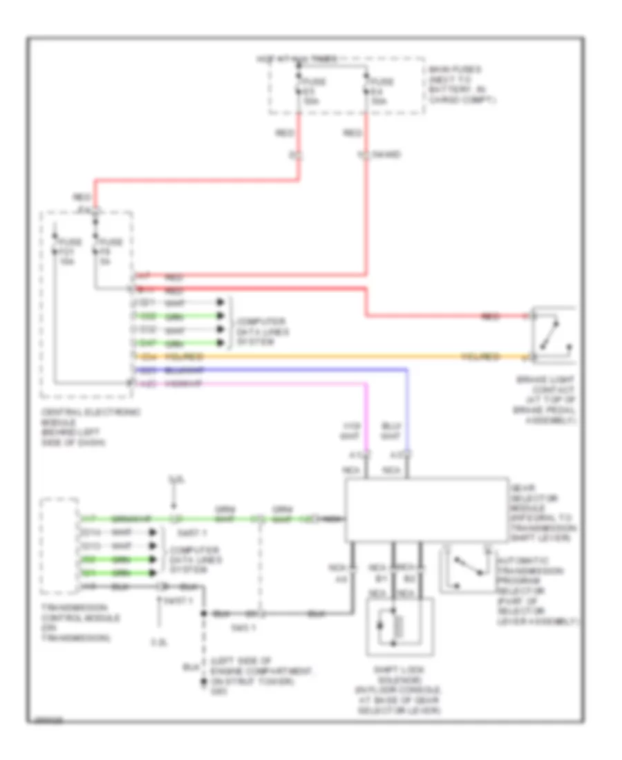
SHIFT INTERLOCK
Shift Interlock Wiring Diagram for Volvo XC90 2011
List of elements for Shift Interlock Wiring Diagram for Volvo XC90 2011:

AIR CONDITIONINGANTI-LOCK BRAKESANTI-THEFTBODY CONTROL MODULESCOMPUTER DATA LINESCOOLING FANCRUISE CONTROLDEFOGGERSELECTRONIC POWER STEERINGENGINE PERFORMANCEEXTERIOR LIGHTSGROUND DISTRIBUTIONHEADLIGHTSHORNINSTRUMENT CLUSTERINTERIOR LIGHTSMEMORY SYSTEMSNAVIGATIONPOWER DISTRIBUTIONPOWER DOOR LOCKSPOWER SEATSPOWER TOP/SUNROOFPOWER WINDOWSRADIOSHIFT INTERLOCKSTARTING/CHARGINGSUPPLEMENTAL RESTRAINTSTRANSMISSIONWARNING SYSTEMSWIPER/WASHER