SUPPLEMENTAL RESTRAINTS
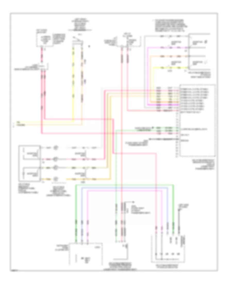
Supplemental Restraints Wiring Diagram (1 of 2) for Chevrolet Impala LT 2013
 https://portal-diagnostov.com/license.html
Automotive Electricians Portal FZCO
Automotive Electricians Portal FZCO
https://portal-diagnostov.com/license.html
https://portal-diagnostov.com/license.html
Automotive Electricians Portal FZCO
Automotive Electricians Portal FZCO
List of elements for Supplemental Restraints Wiring Diagram (1 of 2) for Chevrolet Impala LT 2013:
- (driver's door) inflatable restraint left side impact sensor (sis)
- (front passenger's door) inflatable restraint right side impact sensor (sis)
- (left side of driver's seat back) inflatable restraint left side impact module
- (right "c" pillar)
- (right front
- (right side of front passenger's seat back) inflatable restraint right side impact module
- B12
- C11
- C12
- Driver seat belt buckle
- Driver seat belt pretensioner
- Driver seat belt retractor pretensioner
- Driver seat belt switch
- Inflatable restraint left roof rail module
- Inflatable restraint right front end sensor
- Inflatable restraint right roof rail module
- Inflatable restraint sensing & diagnostic module (under front passenger's seat)
- Left roof rail mod high
- Left roof rail mod low
- Lf end sensor sig
- Lf side impact mod high
- Lf side impact mod low
- Lh pretensioner high
- Lh pretensioner low
- Lh seat belt sw
- Lh seat belt sw low ref
- Lh side impact sensing mod
- Low ref
- Low ref rf end sensor sig
- Nca
- Of engine compt)
- Passenger seat belt buckle
- Passenger seat belt pretensioner
- Passenger seat belt retractor pretensioner
- Passenger seat belt switch
- Pin shorting bars engaged
- Pnk
- Red
- Rf side impact mod high
- Rf side impact mod low
- Rh pretensioner high
- Rh pretensioner low
- Rh roof rail mod high ctrl
- Rh roof rail mod low ctrl
- Rh seat belt sw sig
- Rh side impact sensing mod
- Shorting bar
- Tan
- When module connector is disconnected from harness: (shorting bars are connected between following pins in connector x2: 9-10, 11-12, 17-18, 37-38, 39-40, 53-54)
- X120
- X200
- X311
- X313
- X315
- X316
- X500
- X600
Supplemental Restraints Wiring Diagram (2 of 2) for Chevrolet Impala LT 2013
List of elements for Supplemental Restraints Wiring Diagram (2 of 2) for Chevrolet Impala LT 2013:
- (floor, right of front passenger's seat)
- (i/p harness, near steering column)
- (left front of engine compt)
- (left side
- Air bag
- Air bag fuse 10a
- Airbag/ display fuse 10a
- B11
- B12
- Batt positive volt
- Computer data lines system
- G201
- G302
- G302 (floor, right of front passenger's seat)
- Gnd
- Ground
- Hot at all times
- Hot in run or start
- I/p fuse block (right kick panel)
- I/p mod hi ctrl stage 1
- I/p mod hi ctrl stage 2
- I/p mod lo ctrl stage 1
- I/p mod lo ctrl stage 2
- Ign volt
- Inflatable restraint i/p module (right side of dash)
- Inflatable restraint i/p module indicator
- Inflatable restraint left front end sensor
- Inflatable restraint passenger presence system (pps) module (under front passenger's seat)
- Inflatable restraint sensing & diagnostic module (under front passenger's seat)
- Inflatable restraint steering wheel module (in steering wheel)
- Inflatable restraint steering wheel module coil (under steering wheel)
- Instrument panel cluster (ipc)
- Jx206
- Lo spd gmlan serial data
- Logic
- Of dash)
- Off ind
- On ind
- Passenger
- Pin shorting bars engaged
- Pnk
- Seat belt ind
- Shorting bar
- Steer whl hi ctrl stage 1
- Steer whl hi ctrl stage 2
- Steer whl lo ctrl stage 1
- Steer whl lo ctrl stage 2
- Tan
- Underhood fuse block (right side of engine compt)
- When module connector is disconnected from harness: (shorting bars are connected between following pins in connector x1: 1-2, 3-4, 5-6, 7-8)
- X120
- X200
- X250
- X278
- X313

 Čeština
 Dansk
Dansk Deutsch
 Ελληνικά
 English
 English
 Español
 Suomi
Suomi Français
 Français
 עברית
עברית Hrvatski
 Magyar
 Italiano
 日本語
日本語 한국어
한국어 Nederlands
 Polski
 Português
 Română
 Русский
 Slovenčina
 Slovenščina
 Svenska
 Türkçe
 中文 (中国)