AIR CONDITIONING
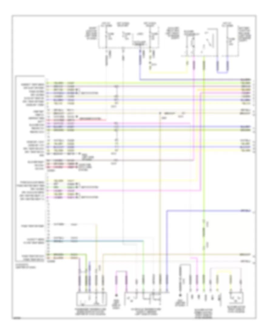
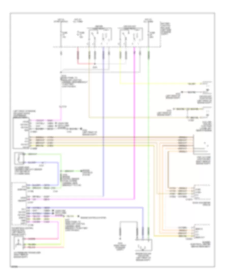
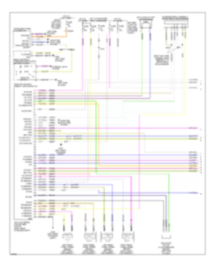
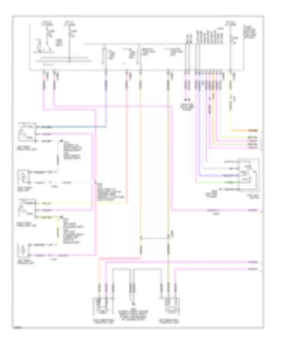
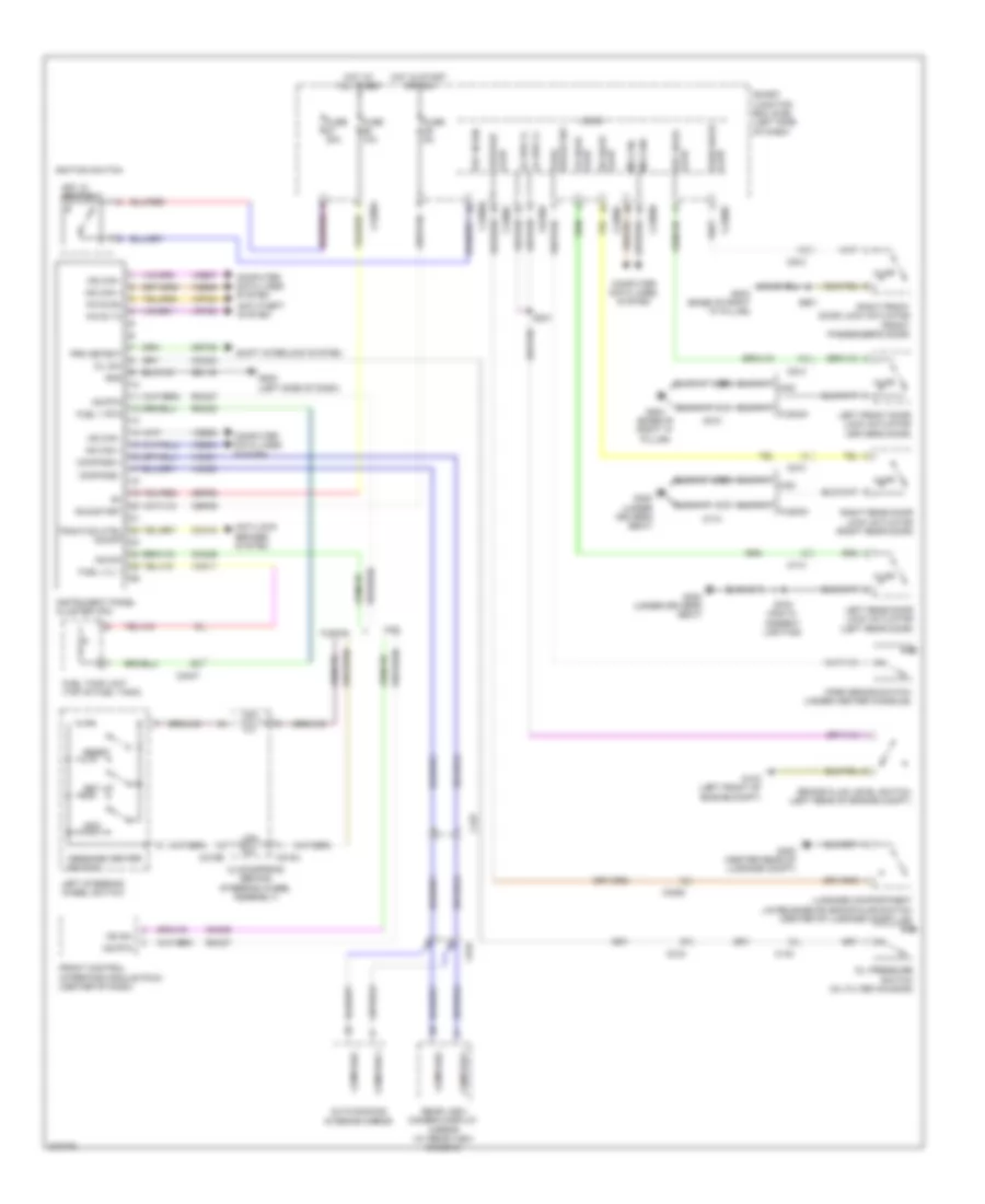
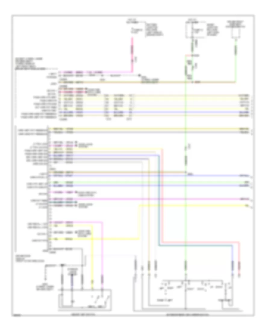
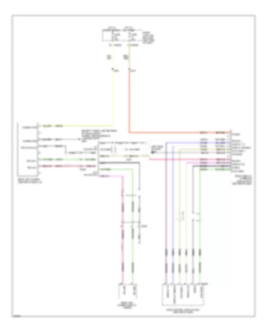
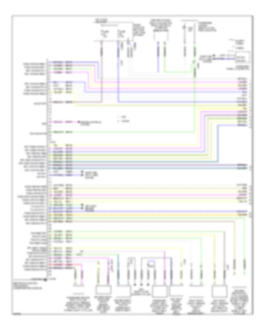
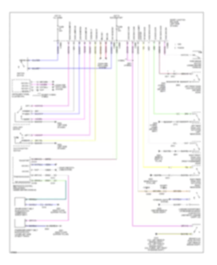
Automatic A/C Wiring Diagram, Except Hybrid (1 of 3) for Ford Fusion S 2012
 https://portal-diagnostov.com/license.html
Automotive Electricians Portal FZCO
Automotive Electricians Portal FZCO
https://portal-diagnostov.com/license.html
https://portal-diagnostov.com/license.html
Automotive Electricians Portal FZCO
Automotive Electricians Portal FZCO
List of elements for Automatic A/C Wiring Diagram, Except Hybrid (1 of 3) for Ford Fusion S 2012:
- Ac evap temp sn
- Air inlet dr fdbk
- Ambient temp sens
- Autolamp sensor
- Batt
- Battery junction box (bjb) (left side of engine compt)
- Blower cmd
- Blower motor (right side of dash)
- Blower motor relay
- Blower motor speed control (right side of hvac housing)
- Blower rqst
- C212
- C213
- C214
- C215
- C2280a
- C2280b
- C2280e
- C2356a
- C2356b
- Ch122
- Ch123
- Ch207
- Ch208
- Ch212
- Ch213
- Ch228
- Ch229
- Ch238
- Ch239
- Chs04
- Chs09
- Chs13
- Chs14
- Chs29
- Chs30
- Cmd
- Computer data lines system
- Defogger system
- Defrost req
- Drv heated seat hi
- Drv heated seat lo
- Drv hs req
- Drv sunload sens
- Drv temp dr ccw
- Drv temp dr cw
- Drv temp dr fdbk
- Fuse 10a
- Fuse 40a
- Fuse 5a
- G201 (center of dash)
- G202 (left side of dash)
- Gd116
- Gnd
- Hot at all times
- Hot in run or acc
- Hvac-datc (center of dash)
- In car temp sens
- In-vehicle temperature sensor (left side of dash)
- Lh111
- Logic
- Mode dr 1 ccw
- Mode dr 1 cw
- Mode dr 1 fdbk
- Mot+
- Mot-
- Ms can+
- Ms can-
- Pass hs req
- Pass ind high
- Pass ind low
- Pass sunload sens
- Pass temp dr ccw
- Pass temp dr cw
- Pass temp dr fdbk
- Passenger temperature blend door actuator (right side of dash)
- Recirc ccw
- Recirc cw
- Rh111
- S131
- Sbp15
- Seats system
- Smart junction box (sjb) (left side of dash)
- Vdb06
- Vdb07
- Vh101
- Vh406
- Vh407
- Vh414
- Vh416
- Vh417
- Vh436
- Vh438
- Vh440
- Vh441
- Vpwr
- Vref 5v
- Vref ret
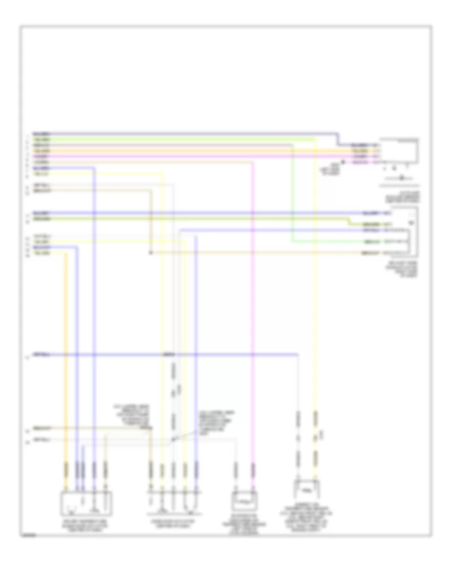
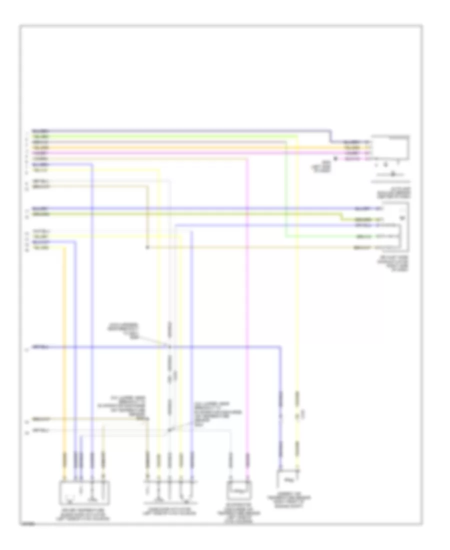
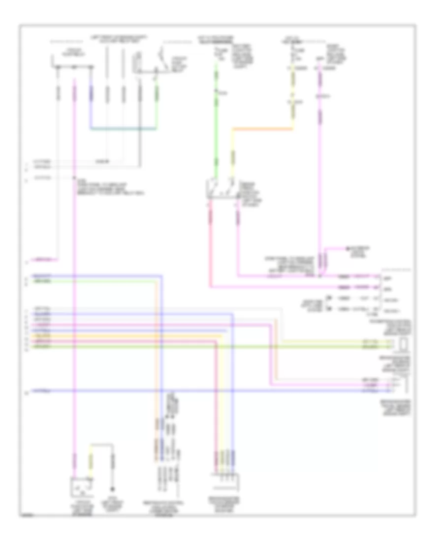
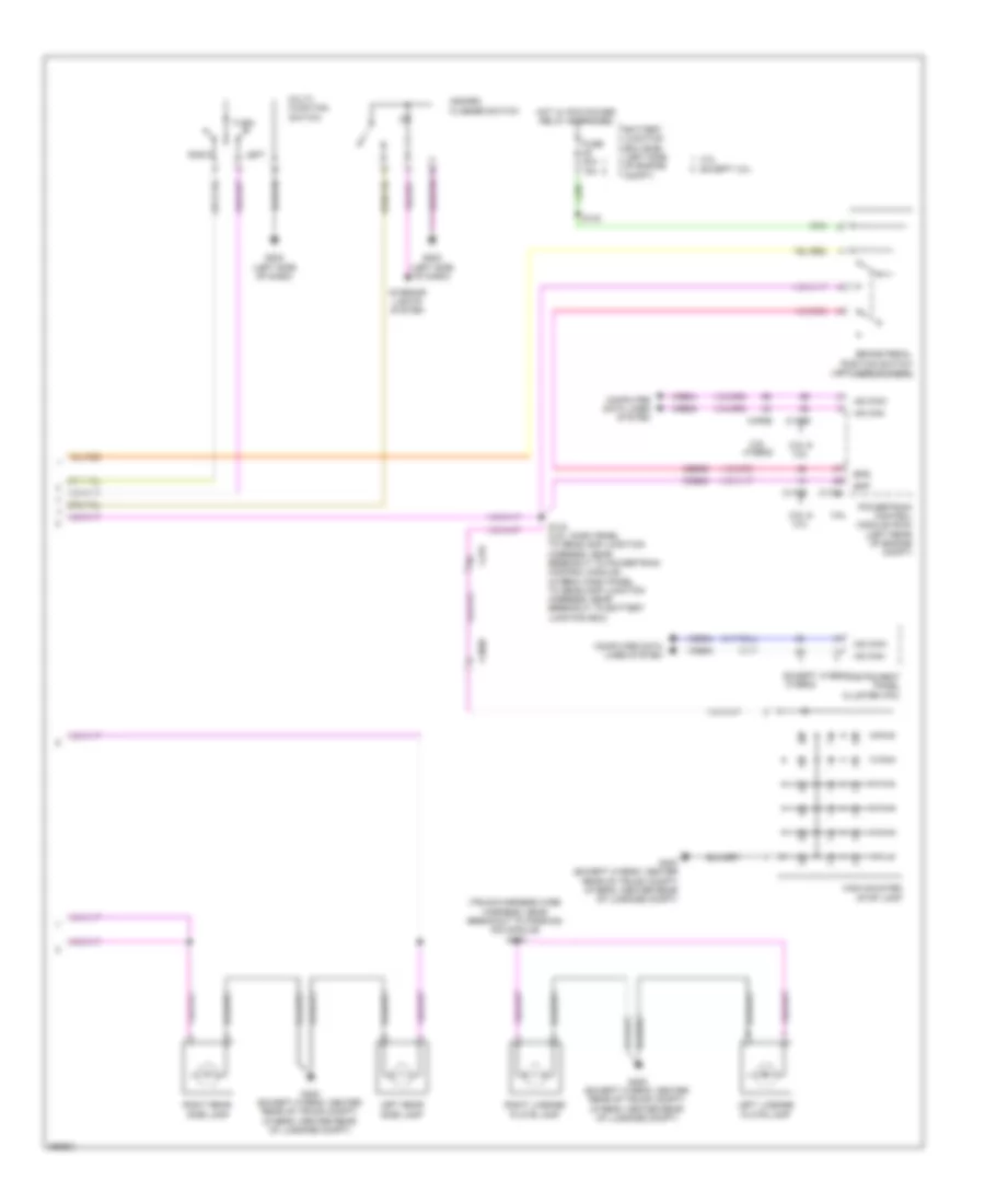
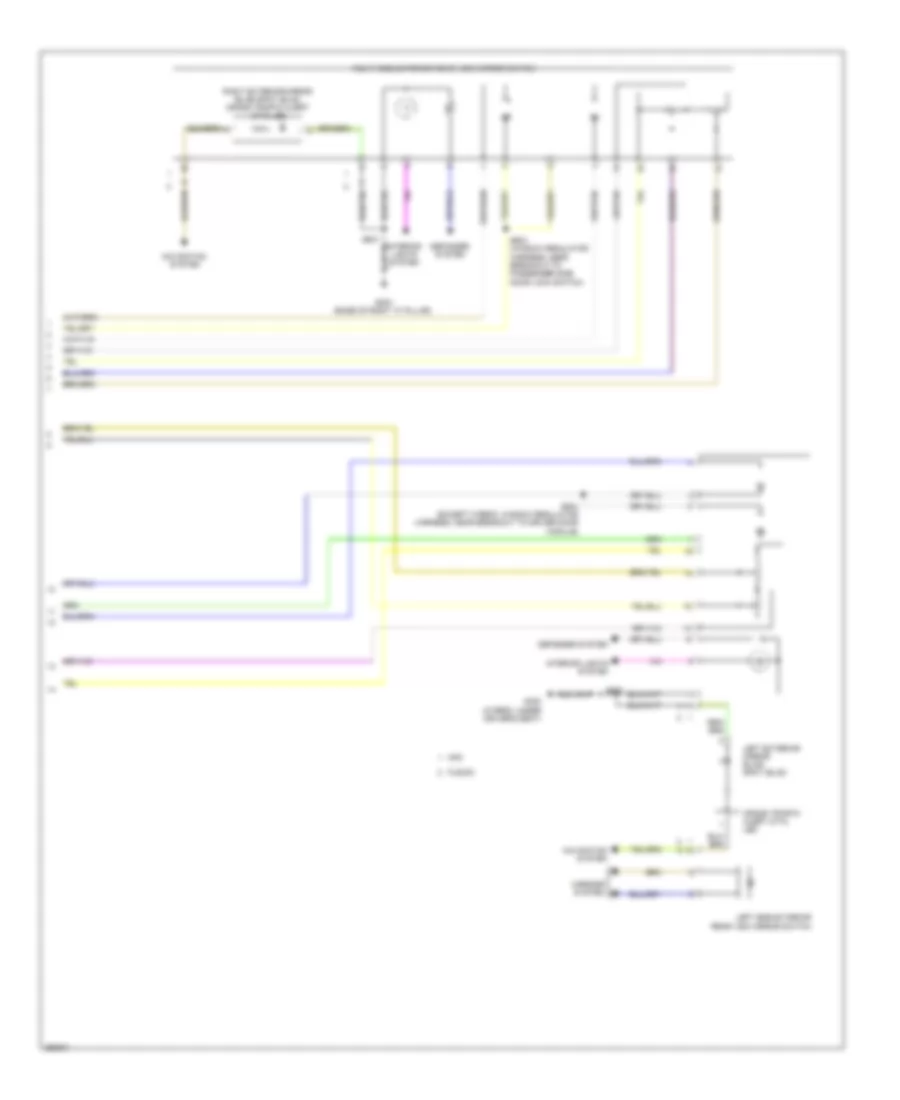
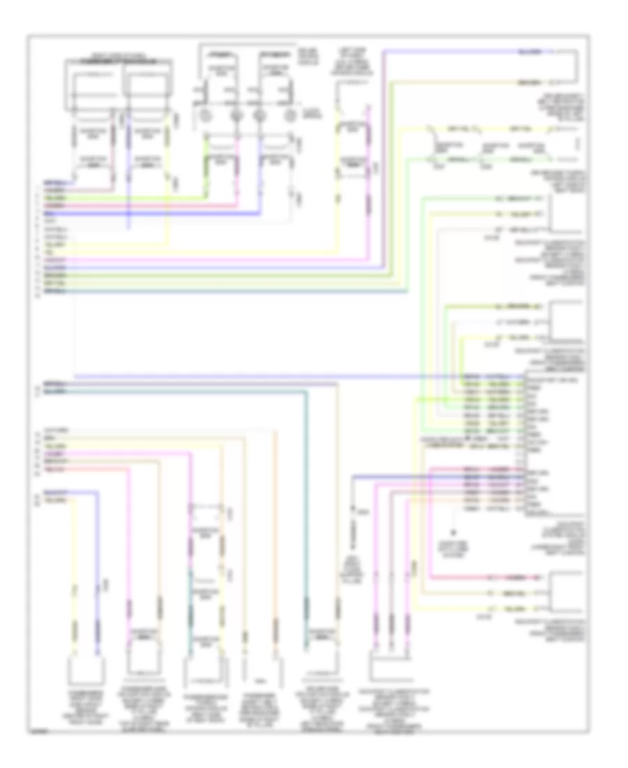
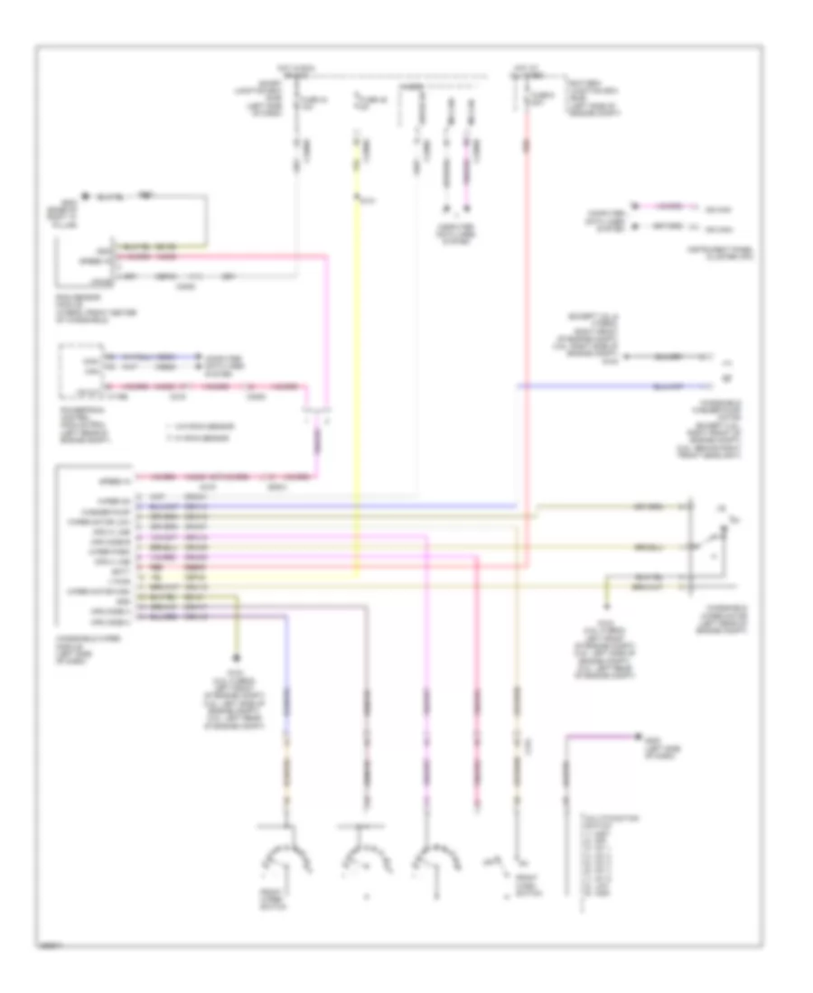
Automatic A/C Wiring Diagram, Except Hybrid (2 of 3) for Ford Fusion S 2012
List of elements for Automatic A/C Wiring Diagram, Except Hybrid (2 of 3) for Ford Fusion S 2012:
- (a/c jumper, near breakout to air conditioner evaporative thermistor) s204
- (a/c jumper, near breakout to air conditioner evaporative thermistor) s206
- Air inlet mode door actuator (right side of dash)
- Ambient air temperature sensor (3.0l: behind front grille) (3.5l: behind right side of front grille) (2.5l: right front of engine compt)
- Autolamp sunload sensor (center of dash)
- C213
- C215
- Driver temperature blend door actuator (center of dash)
- Evaporator discharge air temperature sensor (left side of hvac housing)
- G202 (left side of dash)
- Mode door actuator (center of dash)
- S260
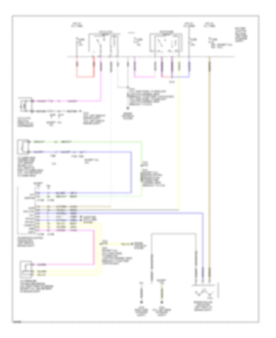
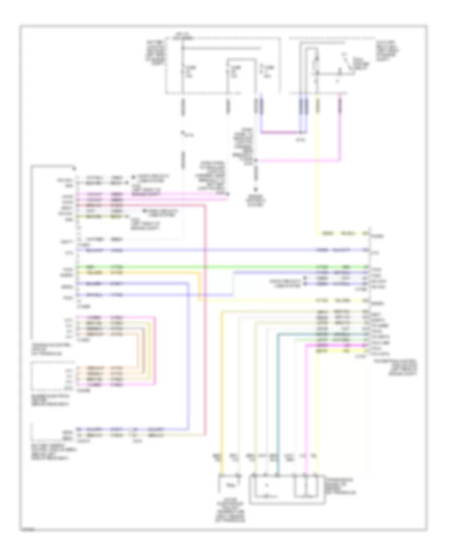
Automatic A/C Wiring Diagram, Except Hybrid (3 of 3) for Ford Fusion S 2012
List of elements for Automatic A/C Wiring Diagram, Except Hybrid (3 of 3) for Ford Fusion S 2012:
- (3.5l)
- (3.5l) s179
- (3.5l) s180
- (except 3.5l) (3.5l)
- 3.5l
- A/c clutch field coil (front of a/c compressor)
- A/c clutch relay
- A/c pressure transducer sensor (2.5l: right front of engine) (except 2.5l: center rear of engine compt)
- Accr
- Acpt
- Battery junction box (bjb) (left side of engine compt)
- Breakout to c133)
- C-sigrtn
- C139
- C144
- C145
- C175b
- C175e
- C192
- Ce302
- Ch302
- Cht
- Computer data lines system
- Cylinder head temperature (cht) sensor (except 3.0l) (3.5l: front of right cylinder head) (2.5l: top center of cylinder head)
- Engine controls system
- Engine cooling fan motor (left front of engine compt)
- Except 3.5l
- Except 3.5l 3.5l
- Fc-v
- Fuse 10a
- Fuse 40a
- Fuse 60a 80a
- G103 (3.0l: left rear of engine compt)
- G103 (3.0l: left rear of engine compt) (3.5l: left side of engine compt)
- G104 (right side of engine compt)
- Hot at all times
- Hs can+
- Hs can-
- Le424
- Pcm ctrl
- Pcm power relay
- Powertrain control module (pcm) (left rear of engine compt)
- Re405
- Re407
- Red
- S143
- S144 (3.0l: dash panel to headlamp junction harness, near breakout to battery junction box) (3.5l: dash panel to headlamp junction harness, near breakout to g103)
- S157 (except 3.5l) (2.5l: dash panel to headlamp junction harness, near breakout to battery junction box)
- Sigrtne
- Vdb04
- Vdb05
- Ve712
- Vec03
- Vh433
- Vref
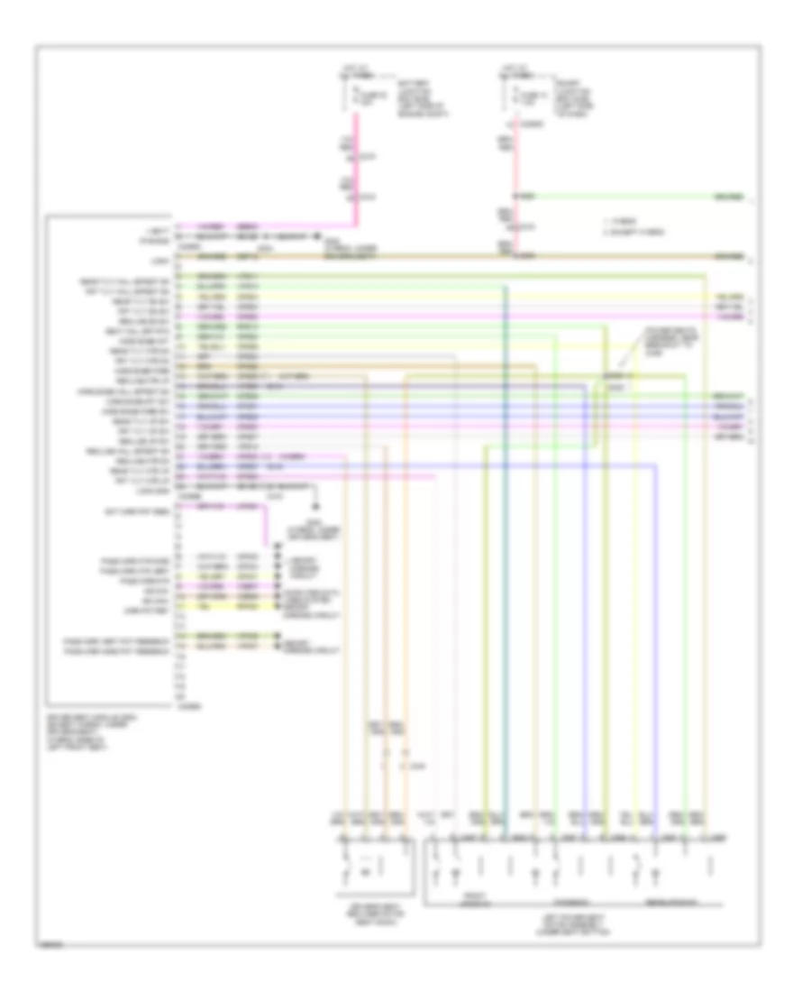
Automatic A/C Wiring Diagram, Hybrid (1 of 3) for Ford Fusion S 2012
List of elements for Automatic A/C Wiring Diagram, Hybrid (1 of 3) for Ford Fusion S 2012:
- Ac evap temp sn
- Air inlet dr fdbk
- Ambient temp sens
- Autolamp sensor
- Auxiliary relay box (left front of engine compt)
- Batt
- Battery junction box (bjb) (left side of engine compt)
- Blower cmd
- Blower motor (right side of hvac housing)
- Blower motor relay
- Blower motor speed control (right side of hvac housing)
- Blower rqst
- C212
- C213
- C214
- C215
- C2280a
- C2280b
- C2280e
- C2356a
- C2356b
- Ch122
- Ch123
- Ch207
- Ch208
- Ch212
- Ch213
- Ch228
- Ch229
- Ch238
- Ch239
- Chs04
- Chs09
- Chs13
- Chs14
- Chs29
- Chs30
- Cmd
- Computer data lines system
- Defogger system
- Defrost req
- Drv heated seat hi
- Drv heated seat lo
- Drv hs req
- Drv sunload sens
- Drv temp dr ccw
- Drv temp dr cw
- Drv temp dr fdbk
- Fuse 10a
- Fuse 40a
- Fuse 5a
- G201 (center of dash)
- G202 (left side of dash)
- Gd116
- Gnd
- Hot at all times
- Hot in run or acc
- Hot in run or start
- Humidity sens
- Hvac-datc (center of dash)
- In car temp sens
- In-vehicle temperature/ humidity sensor (left side of dash)
- Lh111
- Logic
- Mode dr 1 ccw
- Mode dr 1 cw
- Mode dr 1 fdbk
- Mot+
- Mot-
- Ms can+
- Ms can-
- Pass heated seat req
- Pass hs req
- Pass sunload sens
- Pass temp dr ccw
- Pass temp dr cw
- Pass temp dr fdbk
- Passenger temperature blend door actuator (center of hvac housing)
- Recirc ccw
- Recirc cw
- Rh111
- S131
- S261
- Sbp15
- Seats system
- Smart junction box (sjb) (left side of dash)
- Vdb06
- Vdb07
- Vh101
- Vh406
- Vh407
- Vh413
- Vh414
- Vh416
- Vh417
- Vh436
- Vh438
- Vh440
- Vh441
- Vpwr
- Vref 5v
- Vref ret
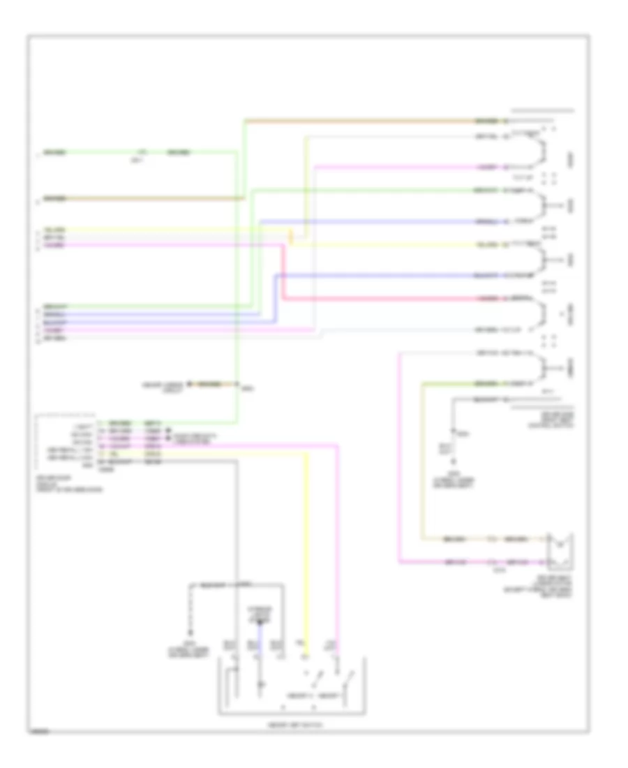
Automatic A/C Wiring Diagram, Hybrid (2 of 3) for Ford Fusion S 2012
List of elements for Automatic A/C Wiring Diagram, Hybrid (2 of 3) for Ford Fusion S 2012:
- (a/c jumper, near breakout to evaporator discharge air temperature sensor s204
- (a/c jumper, near breakout to evaporator discharge air temperature sensor) s206
- (main harness, near breakout to g201) s260
- Air inlet mode door actuator (right side of dash)
- Ambient air temperature sensor (right front of engine compt)
- Autolamp sunload sensor (center of dash)
- C213
- C215
- Driver temperature blend door actuator (left side of hvac housing)
- Evaporator discharge air temperature sensor (left side of hvac housing)
- G202 (left side of dash)
- Mode door actuator (left side of hvac housing)
Automatic A/C Wiring Diagram, Hybrid (3 of 3) for Ford Fusion S 2012
List of elements for Automatic A/C Wiring Diagram, Hybrid (3 of 3) for Ford Fusion S 2012:
- (left front of engine) air conditioning compressor module (accm)
- A/c in
- A/c out
- A/c pressure transducer (right rear of engine compt)
- Acpt
- Auxiliary coolant flow pump (lower left rear of engine)
- Battery junction box (bjb) (left side of engine compt)
- Becm in
- Becm out
- Bussed electrical center (behind rear seat)
- C1026
- C133
- C145
- C1457a
- C1469a
- C1469b
- C175b
- C175e
- C175t
- C4236a
- Ce318
- Ch307
- Ch401
- Cht
- Computer data lines system
- Cyb03
- Cyd01
- Cyd02
- Cylinder head temperature (cht) sensor (top center of cylinder head)
- Dc/dc converter module
- Engine controls system
- Engine cooling fan motor (left front of engine compt)
- Fc-v
- Fuse 10a
- Fuse 15a
- Fuse 60a
- Fvi+
- Fvi-
- G103 (left front of engine compt)
- G104 (right front of engine compt)
- Gd123
- Gnd
- Heater pump relay
- High voltage junction box (right rear of engine compt)
- Hot at all times
- Hot in start or run
- Hpcr
- Hs can+
- Hs can-
- Hv+
- Hv-
- Hvdc+
- Hvdc-
- Hyt03
- Hyt04
- Le424
- M/e coolant pump motor (left front of engine compt)
- M/e coolant pump relay
- Mecspr
- Powertrain control module (pcm) (left rear of engine compt)
- Re405
- Re407
- S144 (dash panel to headlamp junction harness, near breakout to battery junction box)
- S157 (dash panel to headlamp junction harness, near breakout to battery junction box)
- S180 (engine control sensor & fuel charge harness, near breakout to c145)
- S191
- Sigrtn
- Sigrtne
- Vdb04
- Vdb05
- Ve712
- Vec03
- Vh433
- Vpwr
- Vref
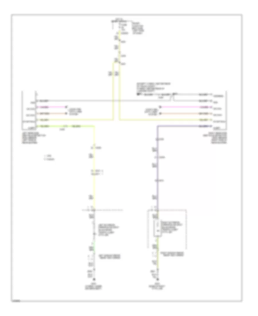
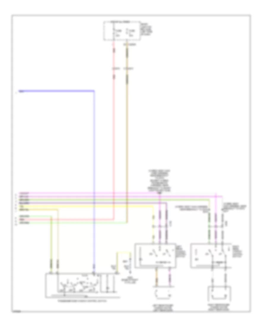
Manual A/C Wiring Diagram (1 of 2) for Ford Fusion S 2012
List of elements for Manual A/C Wiring Diagram (1 of 2) for Ford Fusion S 2012:
- (3.0l: left rear of engine compt) (3.5l: left side of engine compt) g103
- (3.5l)
- (dash panel to headlamp junction harness, near breakout to battery junction box) (except 3.5l) (3.5l) s179
- (except 3.5l)
- (except 3.5l) (3.5l)
- 3.5l
- A/c clutch field coil (front of a/c compressor)
- A/c clutch relay
- A/c pressure transducer sensor (2.5l: right front of engine) (except 2.5l: center rear of engine compt)
- Accr
- Acpt
- Battery junction box (bjb) (left side of engine compt)
- C139
- C144
- C145
- C175b
- C175e
- C192
- Ce302
- Ch302
- Cht
- Computer data lines system
- Cylinder head temperature (cht) sensor (3.5l: front of right cylinder head) (2.5l: top center of cylinder head) (3.0l: rear of engine, near water outlet)
- E-sigrtn
- Engine controls system
- Engine cooling fan motor (left front of engine compt)
- Except 3.5l
- Fc-v
- Fuse 10a
- Fuse 40a
- Fuse 60a 80a
- G103 (3.0l: left rear of engine compt)
- G104 (right side of engine compt)
- Hot at all times
- Hs can+
- Hs can-
- Instrument panel cluster (ipc)
- Le424
- Pcm power relay
- Pcmrc
- Powertrain control module (pcm) (left rear of engine compt)
- Re405
- Re407
- Red
- S143
- S144 (3.5l: dash panel to headlamp junction harness, near breakout to g103)
- S157
- S180 (3.5l)
- S181 (except 3.5l) (engine control sensor & fuel charge wire harness, near breakout to c133)
- Sigrtn
- Vdb04
- Vdb05
- Ve712
- Vec03
- Vh433
- Vref
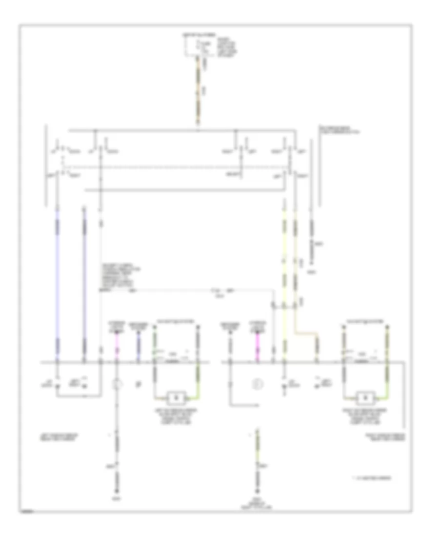
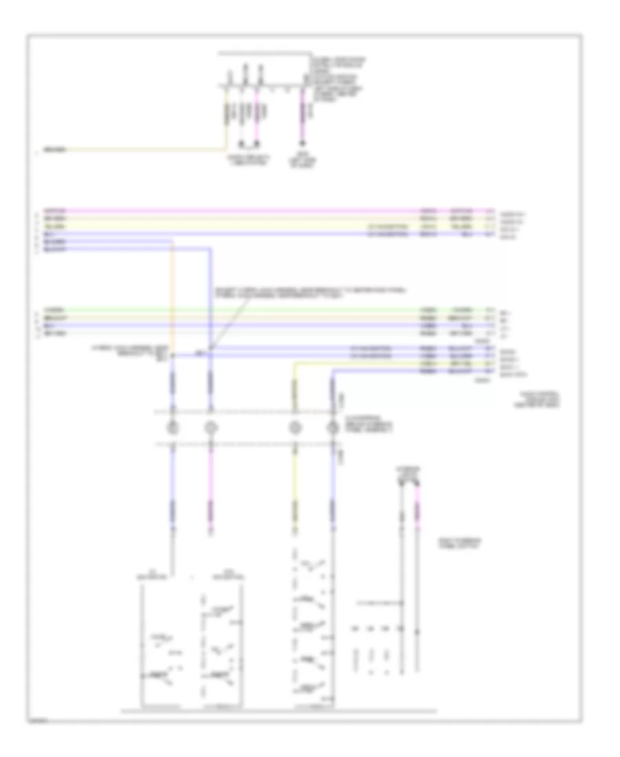
Manual A/C Wiring Diagram (2 of 2) for Ford Fusion S 2012
List of elements for Manual A/C Wiring Diagram (2 of 2) for Ford Fusion S 2012:
- (a/c jumper, near breakout to air conditioner evaporative thermistor)
- (a/c jumper, near breakout to air conditioner evaporative thermistor) s206
- (a/c jumper, near breakout to c298) s205
- (center of dash)
- 1 fdbk
- Actet
- Air inlet mode door actuator (right side of dash)
- Batt power
- Battery junction box (bjb) (left side of engine compt)
- Blower motor (right side of dash)
- Blower motor relay
- Blower motor resistor (right side of hvac housing)
- Blower relay
- C210
- C211
- C214
- C215
- C2280a
- C2280e
- C2357a
- C2357b
- Ch122
- Ch123
- Ch207
- Ch208
- Ch228
- Ch229
- Ch238
- Ch239
- Ch426
- Ch428
- Ch429
- Computer data lines system
- Defogger system
- Defrost req
- Driver temperature blend door actuator (center of dash)
- Drv temp door ccw
- Drv temp door cw
- Dvr temp fdbk
- Evaporator discharge air temperature sensor (left side of hvac housing)
- Fuse 10a
- Fuse 40a
- Fuse 5a
- G201
- G202 (left side of dash)
- Gd115
- Gd116
- Gnd
- High
- Hot at all times
- Hot in run or acc
- Hvac-emtc (center of dash)
- Lh111
- M high
- M low
- Mode door
- Mode door 1 cw mode door 1 ccw
- Mode door actuator (center of dash)
- Ms can+
- Ms can-
- Recir door ccw
- Recir door cw
- Rh111
- S131
- S204
- S215
- Sbp15
- Smart junction box (sjb) (left side of dash)
- Thermal limiter
- Vdb06
- Vdb07
- Vh406
- Vh436
- Vh440
- Vref 5v
- Vref ret
ANTI-LOCK BRAKES
Anti-lock Brakes Wiring Diagram, Except Hybrid for Ford Fusion S 2012
List of elements for Anti-lock Brakes Wiring Diagram, Except Hybrid for Ford Fusion S 2012:
- (2.5l & 3.5l) (3.0l)
- (3.5l: dash panel to headlamp junction harness, near breakout to powertrain control module) s142
- 2.5l & 3.0l
- 2.5l/3.0l
- 20a
- 3.5l
- Anti-lock brake system (abs) module (right front of engine compt)
- Battery junction box (bjb) (left side of engine compt)
- Bpp
- Bpp input
- Bps
- Brake booster vacuum sensor (3.0l awd & 3.5l) (on brake booster)
- Brake pedal position switch (left side of dash)
- C139
- C144
- C175b
- C214
- C215
- C219
- C2280a
- C2280b
- C2280d
- C248
- C310b
- Cbp42
- Cca15
- Cca40
- Ccb08
- Ces09
- Computer data lines system
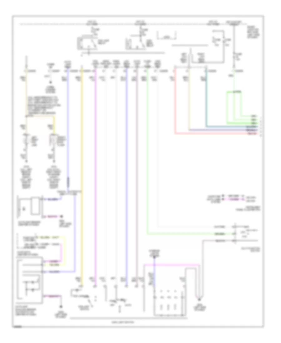
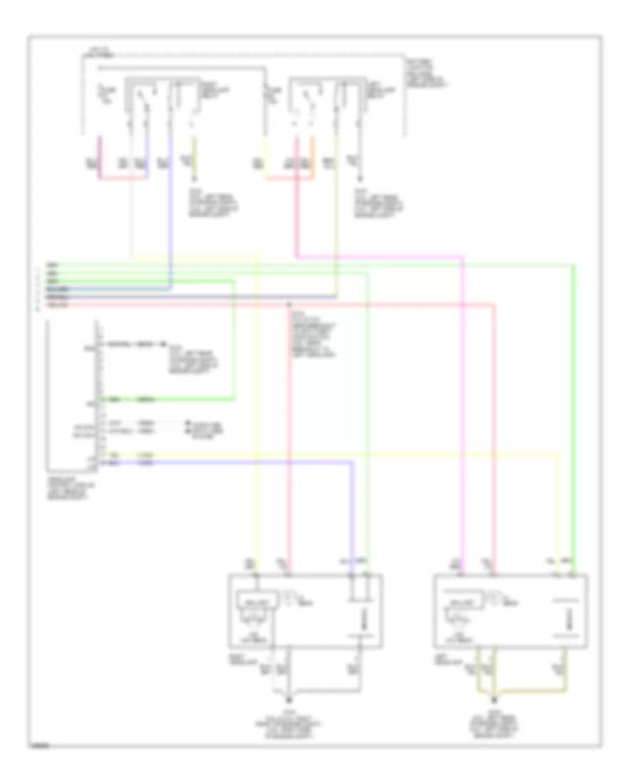
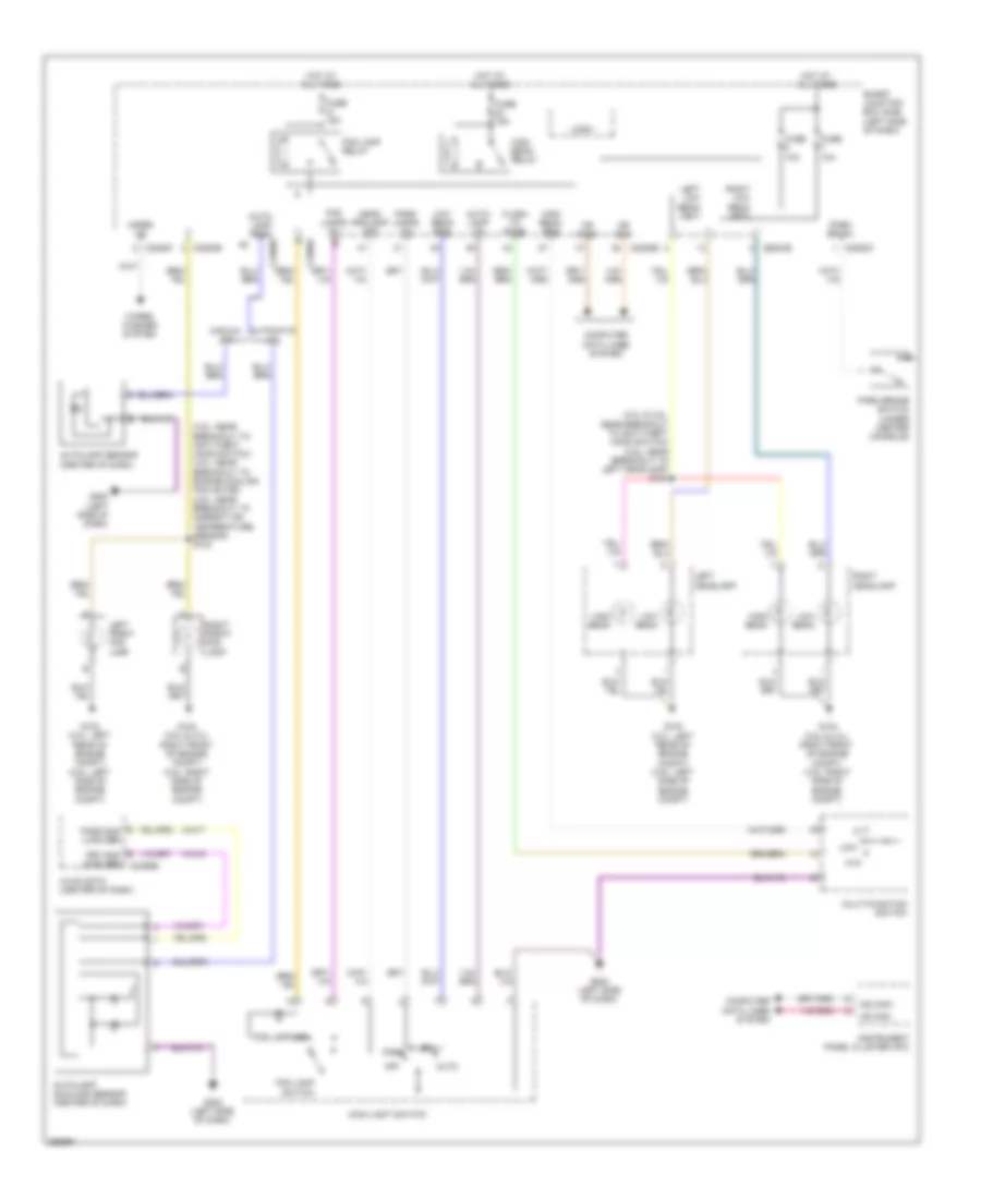
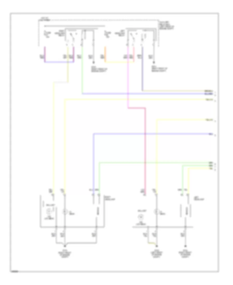
- Exterior lights system
- Front control interface module (fcim) (w/ navigation) (center of dash)
- Fuse 10a
- Fuse 15a
- Fuse 30a
- Fuse 40a
- Fusion
- G104 (2.5l & 3.0l: right front of engine compt) (3.5l: right side of engine compt)
- G202 (left side of dash)
- Gd116
- Gd123
- Gnd
- Hot at all times
- Hot in run or start
- Hot w/ pcm power relay energized
- Hs can +
- Hs can -
- Hs can+
- Hs can-
- Instrument panel cluster (ipc)
- Interior lights system
- Ivd pwr
- Ivd rtn
- Lca37
- Left front wheel speed sensor (left front hub assembly)
- Left rear wheel speed sensor (left rear hub assembly)
- Lf sensor+
- Lf sensor-
- Lr sensor+
- Lr sensor-
- Mkz
- Mtr gnd
- Mtr pwr
- Nca
- Powertrain control module (pcm) (left rear of engine compt)
- Pwr gnd
- Rca17
- Rca18
- Rca19
- Rca20
- Rca37
- Rca40
- Restraints control module (rcm) (under center console)
- Rf sensor+
- Rf sensor-
- Right front wheel speed sensor (right front hub assembly)
- Right rear wheel speed sensor (right rear hub assembly)
- Rr sensor+
- Rr sensor-
- Run/start
- S120
- S140
- Sas a
- Sas b
- Sbb08
- Sbb10
- Smart junction box (sjb) (left side of dash)
- Solid state
- Steering angle sensor module (sasm) (3.5l) (center of steering column)
- Switch traction
- Tc can stat +
- Tc can stat -
- Tc can stat+
- Tc can stat-
- Traction control/ambient lighting switch
- Traction ctl on/off
- Vac gnd
- Vac pwr
- Vac sig
- Valve pwr
- Vca03
- Vca04
- Vca05
- Vca06
- Vca23
- Vca24
- Vca38
- Vca41
- Vca42
- Vdb04
- Vdb05
- Vdbo4
- Vdbo5
Anti-lock Brakes Wiring Diagram, Hybrid (1 of 2) for Ford Fusion S 2012
List of elements for Anti-lock Brakes Wiring Diagram, Hybrid (1 of 2) for Ford Fusion S 2012:
- (body main wire harness, near breakout to brake pedal angle sensor)
- (left side of dash) g202
- (on brake pedal assembly) brake pedal angle sensor
- Anti-lock brake system (abs) module (right rear of engine compt)
- Battery junction box (bjb) (left side of engine compt)
- Bst pwm
- Bst pwr
- C219
- C2280a
- Cbb30
- Cbb31
- Cbb32
- Cbb37
- Cbk03
- Cca15
- Cca22
- Ccb30
- Ccb33
- Computer data lines system
- Front controls interface module (fcim) (center of dash)
- Fuse 10a
- Fuse 30a
- Fuse 50a
- Fuse 5a
- Fusion
- G103 (left front of engine compt)
- G202 (left side of dash)
- Gd116
- Gd121
- Gnd
- Hot at all times
- Hot w/ pcm power relay energized
- Hs can+
- Hs can+ traction ctrl on/off
- Hs can-
- Instrument panel cluster (ipc)
- Interior lights system
- Lca16
- Lca27
- Lca37
- Left front wheel speed sensor (left front hub assembly)
- Left rear wheel speed sensor (left rear hub assembly)
- Lf sensor+
- Lf sensor-
- Lr sensor+
- Lr sensor-
- Mkz
- Mp gnd
- Mp sig
- Mtr pwr
- Nca
- Pas gnd
- Pas sense
- Pas sig 1
- Pas sig 2
- Pm sense
- Ps gnd
- Ps sens
- Ps sig
- Pwr gnd
- Rca16
- Rca17
- Rca18
- Rca19
- Rca20
- Rca27
- Rca37
- Rcb33
- Rf sensor+
- Rf sensor-
- Right front wheel speed sensor (right front hub assembly)
- Right rear wheel speed sensor (right rear hub assembly)
- Rr sensor+
- Rr sensor-
- Run/start
- S144
- S270
- S271
- Sbb08
- Sbb10
- Simulator cut-off valve pressure sensor (left side of dash)
- Simulator cut-off valve solenoid
- Smart junction box (sjb) (left side of dash)
- Tc can stat +
- Tc can stat -
- Tc on/off
- Traction control/ ambient lighting switch
- Traction switch
- Vac
- Vac pump
- Vac pump mon
- Vac sens pwr
- Vac sig 1
- Vac sig 2
- Vacrc
- Valve pwr
- Vca03
- Vca04
- Vca05
- Vca06
- Vca13
- Vca22
- Vca23
- Vca24
- Vca30
- Vca38
- Vca39
- Vca43
- Vcb34
- Vdb04
- Vdb05
- Vol pwm
- Vol pwr
Anti-lock Brakes Wiring Diagram, Hybrid (2 of 2) for Ford Fusion S 2012
List of elements for Anti-lock Brakes Wiring Diagram, Hybrid (2 of 2) for Ford Fusion S 2012:
- (dash panel to headlamp junction harness, near breakout to battery junction box) s142
- (left front of engine compt) auxiliary relay box
- Battery junction box (bjb) (left side of engine compt)
- Bpp
- Bps
- Brake booster solenoid (left rear of engine compt)
- Brake booster travel sensor (left rear of engine compt)
- Brake booster vacuum sensor (on brake booster)
- Brake pedal position switch (left side of dash)
- C175b
- C214
- C219
- C2280b
- C2280d
- C310b
- Ceb08
- Ces09
- Computer data lines system
- Exterior lights system
- Fuse 15a
- G103 (left front of engine compt)
- Hot at all times
- Hot w/ pcm power relay energized
- Hs can +
- Hs can -
- Powertrain control module (pcm) (left rear of engine compt)
- Restraints control module (rcm) (under center console)
- S140
- S190
- S192 (dash panel to headlamp junction harness, near breakout to auxiliary relay box)
- Smart junction box (sjb) (left side of dash)
- System data lines computer
- Tc can stat+
- Tc can stat-
- Vacuum pump cut-off relay
- Vacuum pump motor (left side of engine)
- Vacuum pump relay
- Vca23
- Vca24
- Vdb04
- Vdb05
ANTI-THEFT
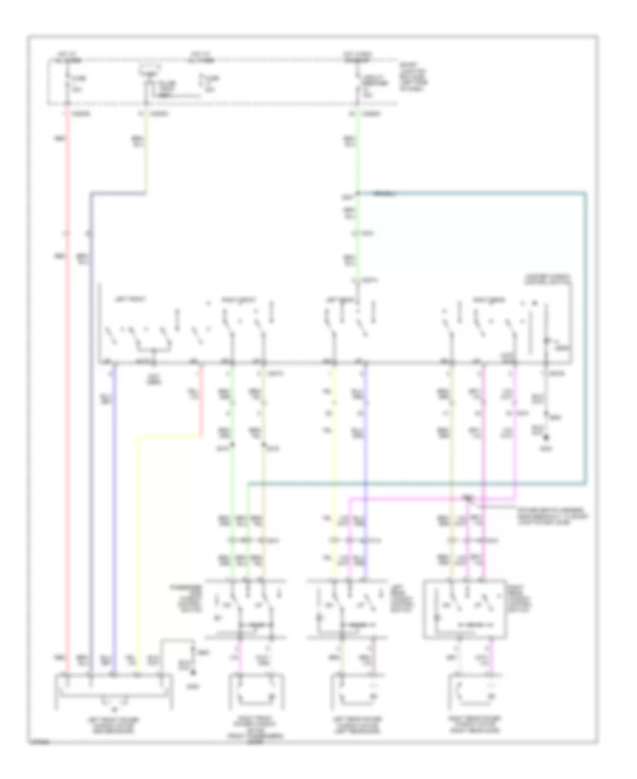
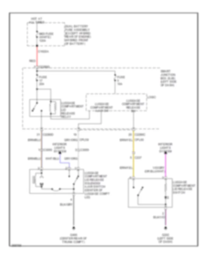
Forced Entry Wiring Diagram (1 of 2) for Ford Fusion S 2012
List of elements for Forced Entry Wiring Diagram (1 of 2) for Ford Fusion S 2012:
- (base of right "a" pillar) g203
- (body main harness, near breakout to g301) s326
- (except hybrid: body main harness, near breakout to c237) s328
- (except hybrid: body main harness, near breakout to g300) s374
- (hybrid: body main harness, near breakout to c510) s324
- (hybrid: body main wire harness, near breakout to c510)
- Accessory delay relay
- All lock relay
- All unlock relay
- C2280c
- C2280d
- C510
- C610
- C710
- C810
- Driver side door lock switch
- Driver unlock relay
- Fuse 15a
- Fuse 20a
- G203 (base of right "a" pillar)
- G300 (hybrid: under driver's seat)
- Hot at all times
- Left rear door lock actuator (left rear door)
- Lock
- Logic
- Lr door ajar
- Pass door ajar
- Passenger side door lock switch
- Power windows system
- Right front door lock actuator (front passenger's door)
- Right rear door lock actuator (right rear door)
- Rr door ajar
- S323
- S329
- S330
- S500
- S601
- S605
- Smart junction box (sjb) (left side of dash)
- Trim lock
- Trim unlock
- Unlock
Forced Entry Wiring Diagram (2 of 2) for Ford Fusion S 2012
List of elements for Forced Entry Wiring Diagram (2 of 2) for Ford Fusion S 2012:
- 1/2
- 3/4
- 5/6
- 7/8
- 9/0
- Anti-theft hood switch (left front of engine compt)
- C2280c
- C2280f
- C3050
- C510
- Disarm request
- Driver door ajar
- Fuse 10a
- G104 (except 3.5l: right front of engine compt) (3.5l: right side of engine compt)
- G300 (hybrid: under driver's seat)
- G400 (center rear of trunk compt)
- Hood ajar
- Hot at all times
- Keypad a
- Keypad b
- Keypad c
- Keypad illum (fet)
- Keypad switch assembly
- Left front door lock actuator (driver's door)
- Logic
- Luggage compartment disarm switch (center rear of luggage compt)
- Reset
- Rke receiver internal ant
- S500
- Set
- Smart junction box (sjb) (left side of dash)
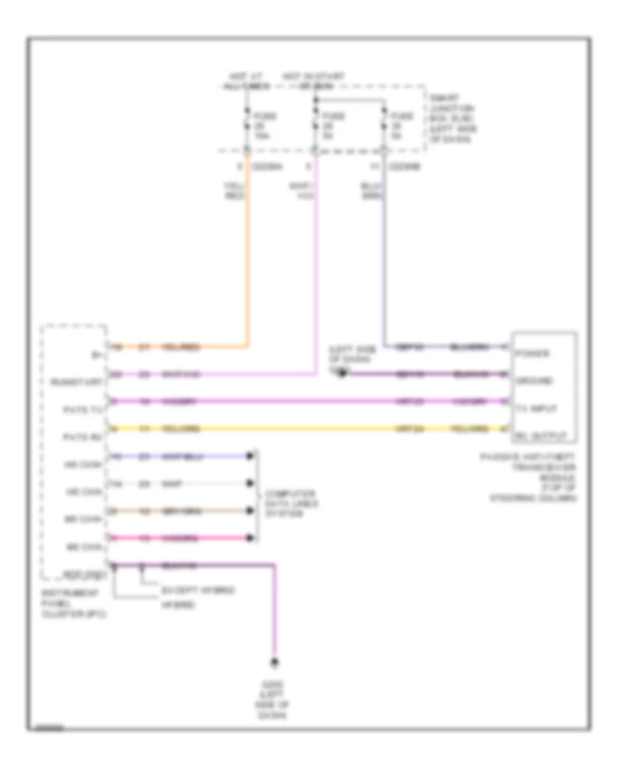
Passive Anti-theft Wiring Diagram for Ford Fusion S 2012
List of elements for Passive Anti-theft Wiring Diagram for Ford Fusion S 2012:
- (left side of dash) g202
- C2280a
- C2280b
- Cbp36
- Computer data lines system
- Except hybrid
- Fuse 10a
- Fuse 5a
- G202 (left side of dash)
- Gd116
- Ground
- Hot at all times
- Hot in start or run
- Hs can+
- Hs can-
- Hybrid
- Instrument panel cluster (ipc)
- Mod gnd
- Ms can+
- Ms can-
- Passive anti-theft transceiver module (top of steering column)
- Pats rx
- Pats tx
- Power
- Run/start
- Rx output
- Smart junction box (sjb) (left side of dash)
- Tx input
- Vrt23
- Vrt24
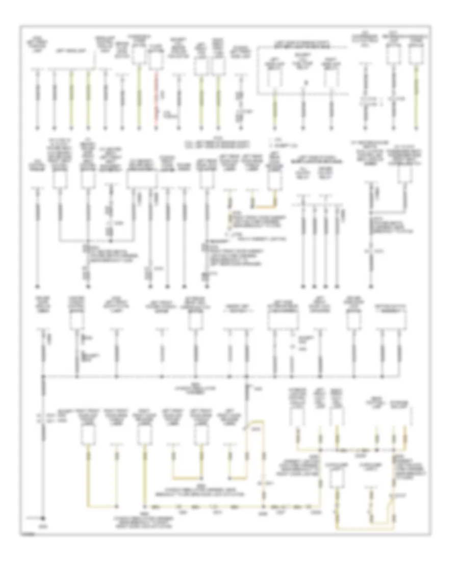
BODY CONTROL MODULES
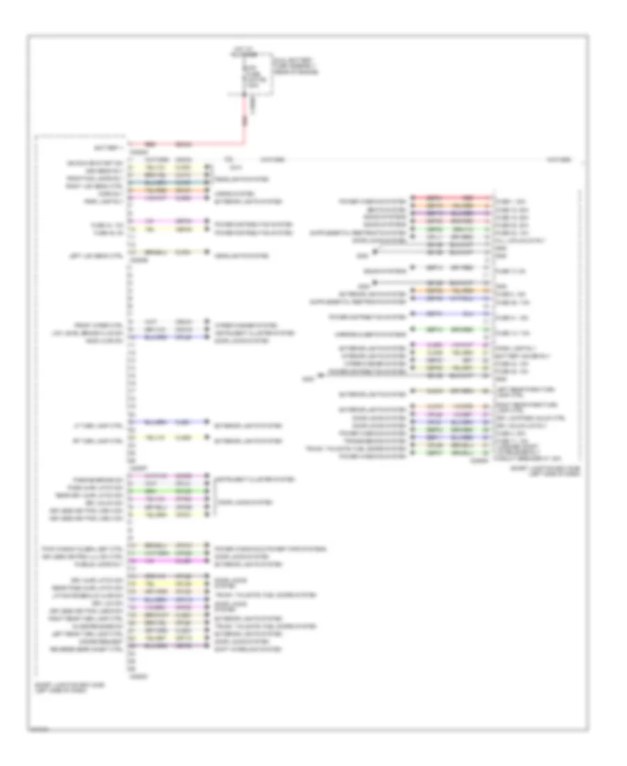
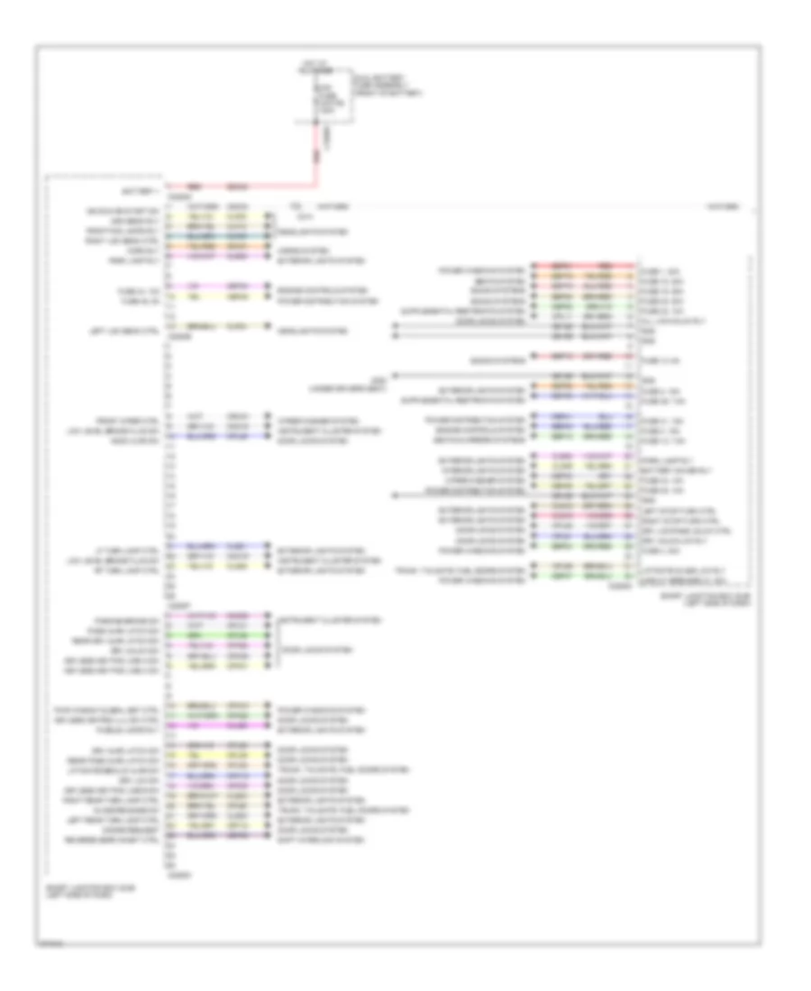
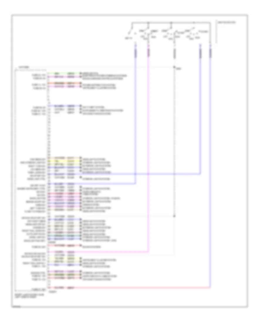
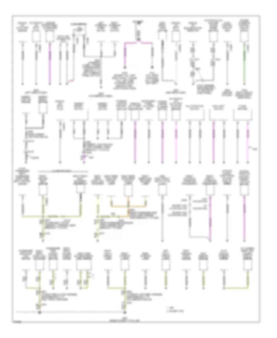
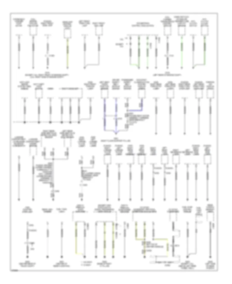
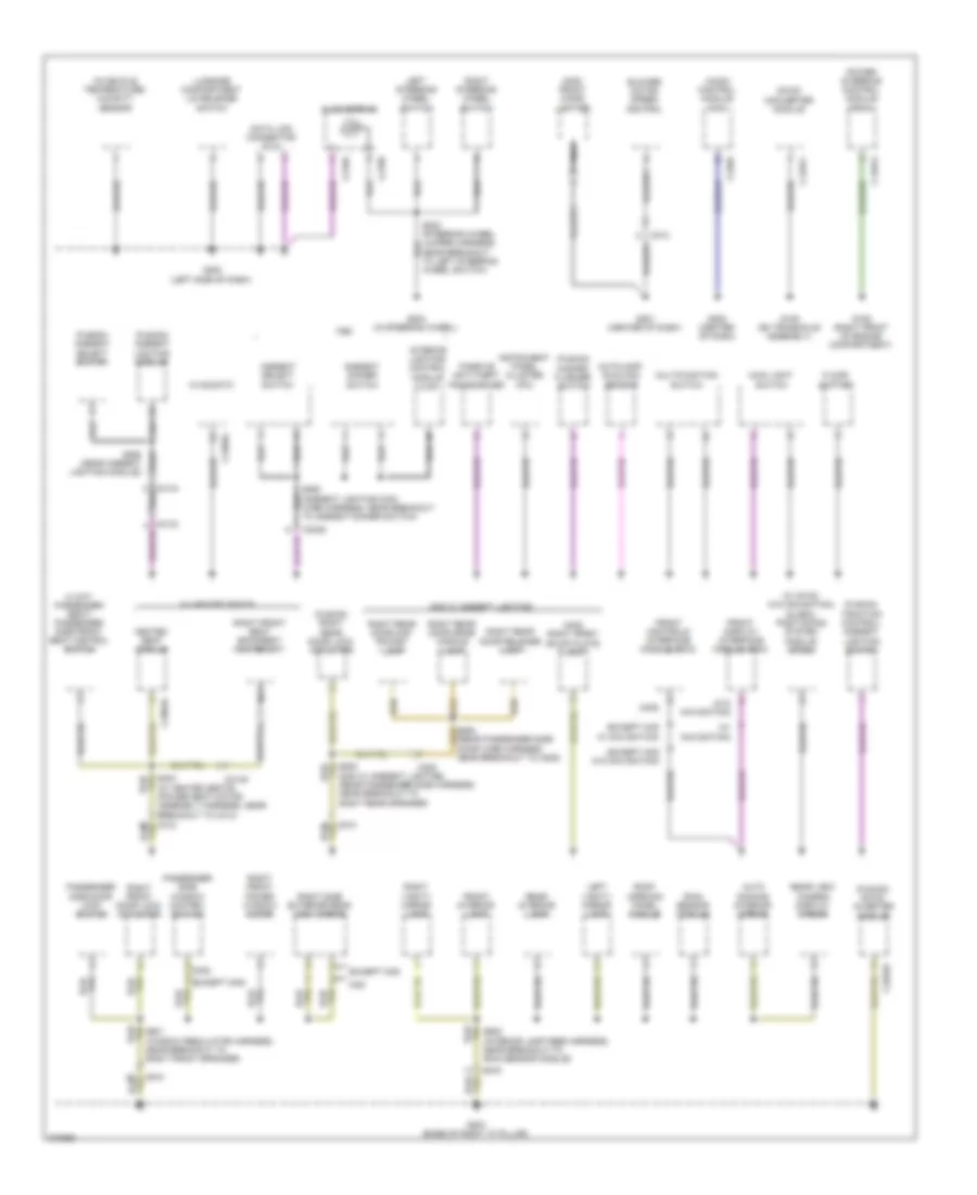
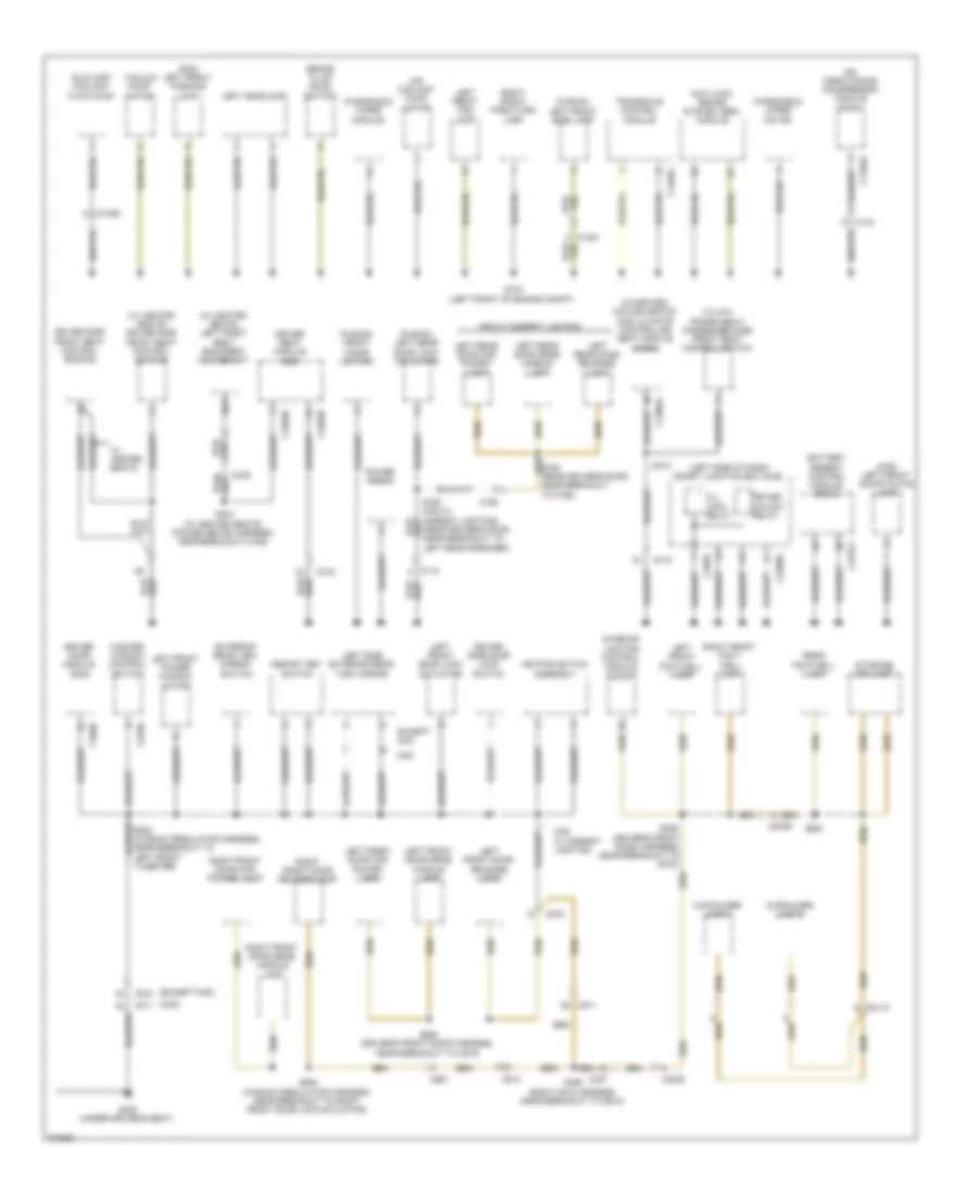
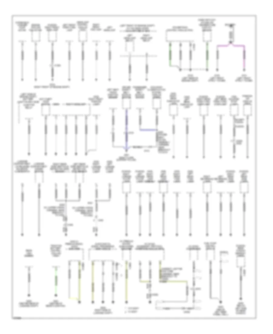
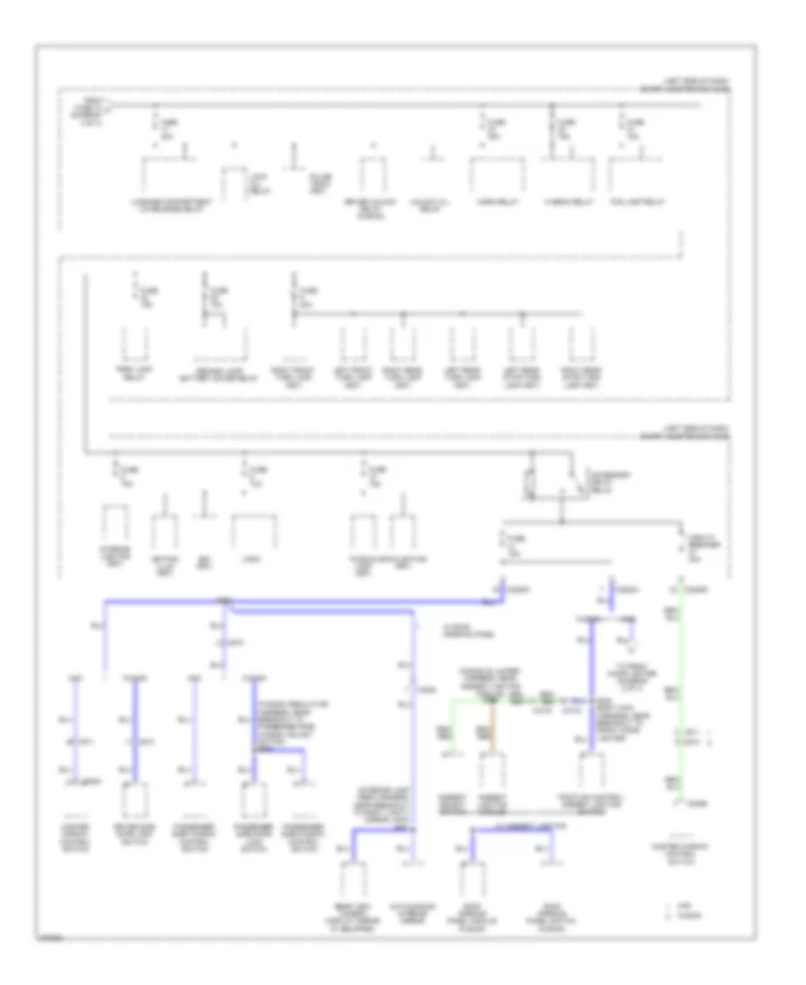
Body Control Modules Wiring Diagram, Except Hybrid (1 of 2) for Ford Fusion S 2012
List of elements for Body Control Modules Wiring Diagram, Except Hybrid (1 of 2) for Ford Fusion S 2012:
- All lck/unlck rly
- Battery +
- Battery saver rly
- C1620a
- C214
- C2280c
- C2280d
- C2280e
- C2280f
- C2280g
- Cbp32
- Cbp35
- Cbp41
- Cbp43
- Cbp44
- Cbp45
- Cbp46
- Cbp47
- Cdc34
- Cet53
- Clf04
- Clf05
- Clf08
- Clf12
- Cln09
- Cln25
- Cls18
- Cls19
- Cls21
- Cls23
- Cls24
- Cls25
- Cls30
- Cmc19
- Cmc25
- Cpk19
- Cpk23
- Cpk28
- Cpk29
- Cpk30
- Cpk31
- Cpl11
- Cpl25
- Cpl26
- Cpl31
- Cpl36
- Cpl39
- Cpl51
- Cpl52
- Cpl58
- Cpl59
- Cpl60
- Cpw01
- Crt18
- Crw01
- Disarm request
- Door locks system
- Drv ajar latch sw
- Drv lck sw
- Drv lck/pass unlck ctrl
- Drv unlck sw
- Drv unlck/lck rly
- Dual battery fuse assembly (rear of engine)
- Exterior lights system
- Front fog lamps rly
- Front wiper ctrl
- Fuse 1, 30a
- Fuse 11, 10a luggage compt lid release rly circuit breaker 47, 30a
- Fuse 12, 7.5a
- Fuse 13, 5a
- Fuse 18, 20a
- Fuse 19, 25a
- Fuse 2, 15a
- Fuse 32, 10a
- Fuse 35, 10a
- Fuse 38, 20a
- Fuse 4, 30a
- Fuse 41, 15a
- Fuse 43, 10a
- Fuse 44, 10a
- Fuse 45, 5a
- Fuse 46, 7.5a
- G300
- Gd126
- Glass release sw
- Gnd
- Headlights system
- High beam rly
- Hood ajar sw
- Horn rly
- Horns system
- Hot at all times
- Ign run or start sw
- Instrument cluster system
- Interior lights system
- Keyless key pad line a sw
- Keyless key pad line b sw
- Keyless key pad line c sw
- Keyless keypad illu sw ctrl
- Left low beam ctrl
- Left rear park/turn lamp ctrl
- Left rear turn lamp ctrl
- Lf turn lamp ctrl
- Liftgate/decklid ajar sw
- Low level brake fluid sw
- Midi fuse (white) 120a
- Mirrors & seats systems
- Park lamp rly
- Parking brake sw
- Pass ajar latch sw
- Power distribution system
- Power windows & power tops systems
- Power windows system
- Puddle lamps rly
- Pwr window global set ctrl
- Rear drv ajar latch sw
- Rear pass ajar latch sw
- Red
- Reverse gear inhibit ctrl
- Rf turn lamp ctrl
- Right low beam ctrl
- Right rear park/turn lamp ctrl
- Right rear turn lamp ctrl
- Sbp01
- Sbp02
- Sbp04
- Sbp11
- Sbp12
- Sbp13
- Sbp18
- Sbp19
- Sbp38
- Sdc02
- Seats system
- Shift interlock system
- Smart junction box (sjb) (left side of dash)
- Sound systems
- Srh01
- Transmissions system
- Trunk, tailgate, fuel doors system
- Wiper/washer system
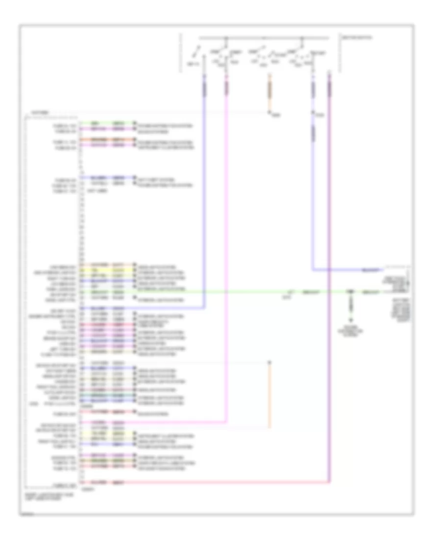
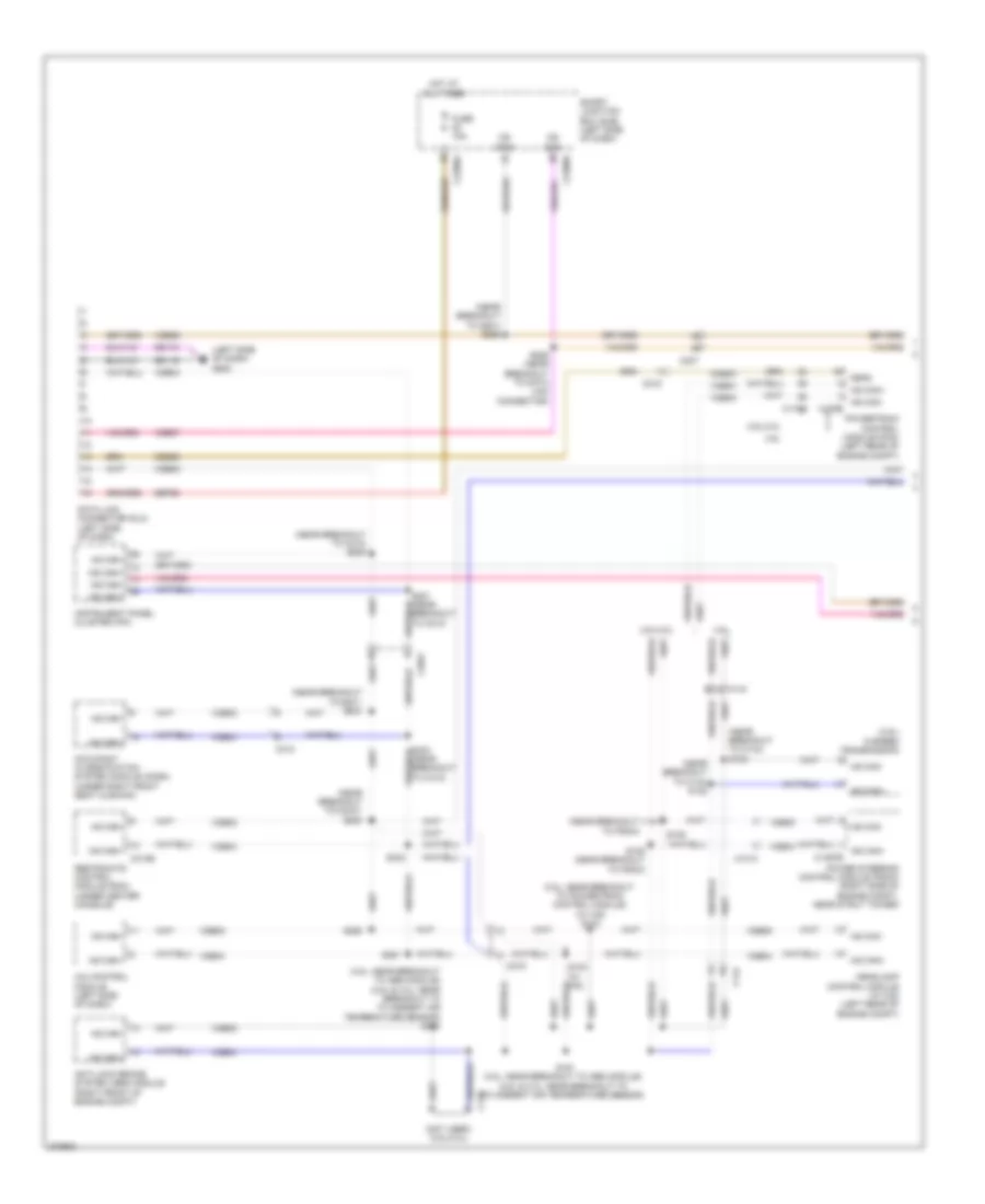
Body Control Modules Wiring Diagram, Except Hybrid (2 of 2) for Ford Fusion S 2012
List of elements for Body Control Modules Wiring Diagram, Except Hybrid (2 of 2) for Ford Fusion S 2012:
- (mkz)
- (not used)
- Add interior lamp sw
- Air conditioning system
- Anti-theft system
- Autolamp on sw
- Battery junction box (bjb) (left side of engine compt)
- Brake on/off sw
- C215
- C2280a
- C2280b
- Cbp28
- Cbp29
- Cbp36
- Cbp41
- Cbp42
- Cbp46
- Ccb08
- Cdc30
- Cdc33
- Cdc34
- Ce336
- Clf12
- Clf17
- Clf18
- Clf19
- Clf21
- Clf23
- Clf27
- Cln12
- Cln27
- Cln28
- Cls32
- Cls34
- Cls39
- Cls41
- Computer data lines system
- Crh02
- Day/night sens
- Dimmer instrument ctrl
- Dimming ctrl
- Dome lamp ctrl
- Dome lamp sw
- Exterior lights system
- Flash to pass sw
- Front fog lamp rly
- Front fog lamps sw
- Fuse 14, 10a
- Fuse 15, 10a
- Fuse 20, 15a
- Fuse 26, 10a
- Fuse 27, 20a
- Fuse 28, 5a
- Fuse 29, 5a
- Fuse 36, 5a
- Fuse 37, 10a
- Fuse 39, 20a
- Fuse 41, 15a
- Fuse 42, 10a
- Fuse 46, 7.5a
- Hazard sw
- Headlamp off sw
- Headlights system
- High beam sw
- Horn sw
- Horns system
- Ign key in sw
- Ign run or acc sw
- Ign run or start sw
- Ign start sw
- Ignition switch
- Instrument cluster system
- Interior lights system
- Ip sw illu 2 ctrl
- Ip sw illu ctrl
- Key in
- Lck acc
- Left turn sw
- Low beam sw
- Ms can+
- Ms can-
- Off
- One touch integrated start dtode
- Park lamps sw
- Power distribution system
- Right turn sw
- Rln29
- Run
- S151
- S152
- S250
- Sbp14
- Sbp15
- Sbp20
- Sbp26
- Sbp27
- Sbp39
- Smart junction box (sjb) (left side of dash)
- Sound systems
- Start
- Vdb06
- Vdb07
- Vlf14
- Vln04
- Vln33
- Vln37
Body Control Modules Wiring Diagram, Hybrid (1 of 2) for Ford Fusion S 2012
List of elements for Body Control Modules Wiring Diagram, Hybrid (1 of 2) for Ford Fusion S 2012:
- All lck/unlck rly
- Battery +
- Battery saver rly
- C1620a
- C214
- C2280c
- C2280d
- C2280e
- C2280f
- C2280g
- Cbp32
- Cbp35
- Cbp41
- Cbp43
- Cbp44
- Cbp45
- Cbp46
- Cbp47
- Cdc34
- Cet53
- Circuit breaker 47, 30a
- Clf04
- Clf05
- Clf08
- Clf12
- Cln09
- Cln25
- Cls18
- Cls19
- Cls21
- Cls23
- Cls24
- Cls25
- Cls30
- Cmc19
- Cmc25
- Cpk19
- Cpk23
- Cpk28
- Cpk29
- Cpk30
- Cpk31
- Cpl11
- Cpl25
- Cpl26
- Cpl31
- Cpl36
- Cpl39
- Cpl51
- Cpl52
- Cpl58
- Cpl59
- Cpl60
- Cpw01
- Crt18
- Crw01
- Disarm request
- Door locks system
- Drv ajar latch sw
- Drv lck sw
- Drv lck/pass unlck ctrl
- Drv unlck sw
- Drv unlck/lck rly
- Dual battery fuse assembly (front of battery)
- Engine controls system
- Exterior lights system
- Front fog lamps rly
- Front wiper ctrl
- Fuse 1, 30a
- Fuse 12, 7.5a
- Fuse 13, 5a
- Fuse 18, 20a
- Fuse 19, 25a
- Fuse 2, 15a
- Fuse 3, 15a
- Fuse 32, 10a
- Fuse 35, 10a
- Fuse 38, 20a
- Fuse 4, 30a
- Fuse 41, 15a
- Fuse 43, 10a
- Fuse 44, 10a
- Fuse 45, 5a
- Fuse 46, 7.5a
- G300 (under driver's seat)
- Gd126
- Glass release sw
- Gnd
- Headlights system
- High beam rly
- Hood ajar sw
- Horn rly
- Horns system
- Hot at all times
- Ign run or start sw
- Instrument cluster system
- Interior lights system
- Keyless key pad line a sw
- Keyless key pad line b sw
- Keyless key pad line c sw
- Keyless keypad illu sw ctrl
- Left low beam ctrl
- Left rear turn lamp ctrl
- Left stop/turn ctrl
- Lf turn lamp ctrl
- Liftgate glass lck rly
- Liftgate/decklid ajar sw
- Low level brake fluid sw
- Midi fuse (white) 120a
- Park lamp rly
- Parking brake sw
- Pass ajar latch sw
- Power distribution system
- Power windows system
- Puddle lamps rly
- Pwr window global set ctrl
- Rear drv ajar latch sw
- Rear pass ajar latch sw
- Red
- Reverse gear inhibit ctrl
- Rf turn lamp ctrl
- Right low beam ctrl
- Right rear turn lamp ctrl
- Right stop/turn ctrl
- Sbp01
- Sbp02
- Sbp03
- Sbp04
- Sbp12
- Sbp13
- Sbp18
- Sbp19
- Sbp38
- Sdc02
- Seats & mirrors systems
- Seats system
- Shift interlock system
- Smart junction box (sjb) (left side of dash)
- Sound systems
- Srh01
- Trunk, tailgate, fuel doors system
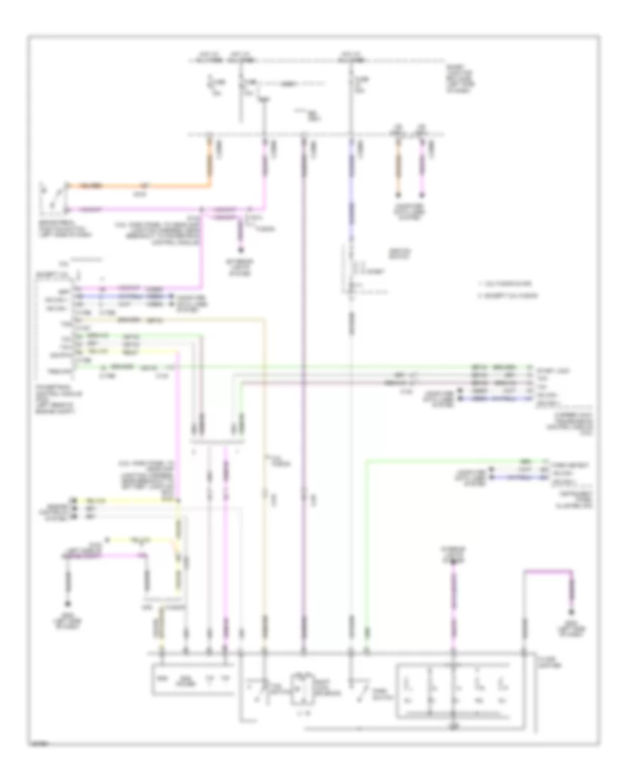
- Wiper/washer system
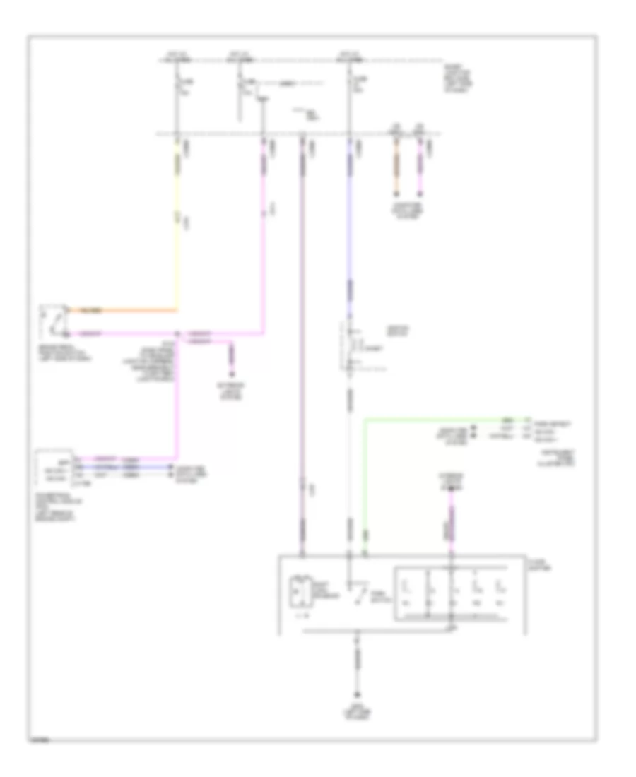
Body Control Modules Wiring Diagram, Hybrid (2 of 2) for Ford Fusion S 2012
List of elements for Body Control Modules Wiring Diagram, Hybrid (2 of 2) for Ford Fusion S 2012:
- (fusion)
- (mkz)
- Add interior lamp sw
- Air conditioning system
- Anti-theft system
- Autolamp on sw
- Backlighting
- Backlighting (fet)
- Brake on/off sw
- C2280a
- C2280b
- Cbp28
- Cbp29
- Cbp36
- Cbp37
- Cbp41
- Cbp42
- Cbp46
- Ccb08
- Cdc30
- Cdc33
- Cdc34
- Cdc35
- Clf12
- Clf17
- Clf18
- Clf19
- Clf21
- Clf23
- Clf27
- Cln12
- Cln27
- Cln28
- Cls32
- Cls34
- Cls39
- Cls41
- Computer data lines system
- Crh02
- Day/night sens
- Dimmer instrument ctrl
- Dimming ctrl
- Dome lamp ctrl
- Dome lamp sw
- Exterior lights system
- Flash to pass sw
- Front fog lamp rly
- Front fog lamps sw
- Fuse 14, 10a
- Fuse 15, 10a
- Fuse 20, 15a
- Fuse 26, 10a
- Fuse 27, 20a
- Fuse 28, 5a
- Fuse 29, 5a
- Fuse 36, 5a
- Fuse 37, 10a
- Fuse 39, 20a
- Fuse 41, 15a
- Fuse 42, 10a
- Fuse 46, 7.5a
- Hazard sw
- Headlamp off sw
- Headlights & electronic power steering systems
- Headlights system
- High beam sw
- Horn sw
- Horns system
- Ign key in sw
- Ign run or acc sw
- Ign run or start sw
- Ign start sw
- Ignition switch
- Instrument cluster system
- Interior lights system
- Key in
- Lck acc
- Left turn sw
- Low beam sw
- Ms can+
- Ms can-
- Off
- Park lamps sw
- Power distribution system
- Right turn sw
- Rln29
- Run
- S250
- Sbp14
- Sbp15
- Sbp20
- Sbp26
- Sbp27
- Sbp39
- Smart junction box (sjb) (left side of dash)
- Sound & engine controls systems
- Sound systems
- Start
- Vdb06
- Vdb07
- Vlf14
- Vln04
- Vln33
- Vln37
COMPUTER DATA LINES
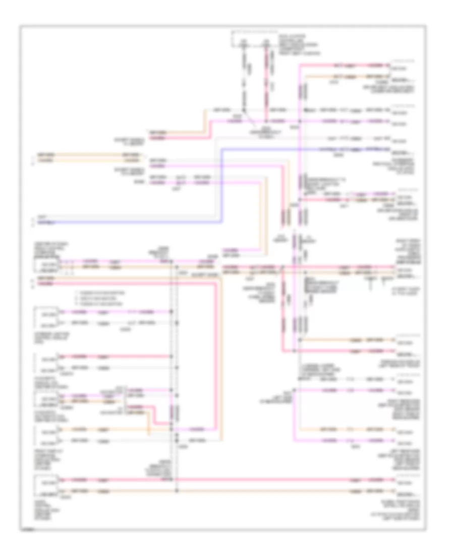
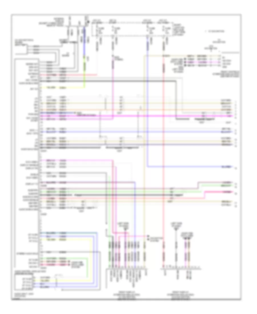
Computer Data Lines Wiring Diagram, Except Hybrid (1 of 2) for Ford Fusion S 2012
List of elements for Computer Data Lines Wiring Diagram, Except Hybrid (1 of 2) for Ford Fusion S 2012:
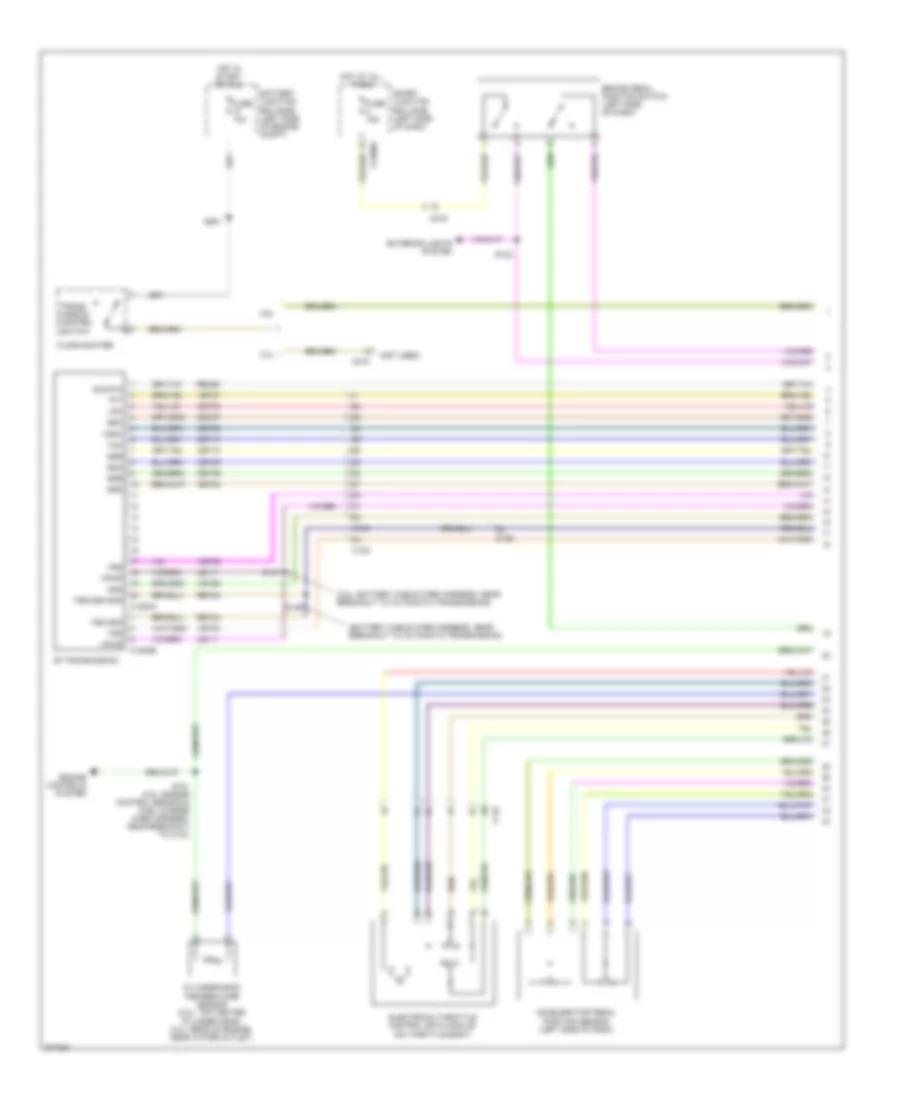
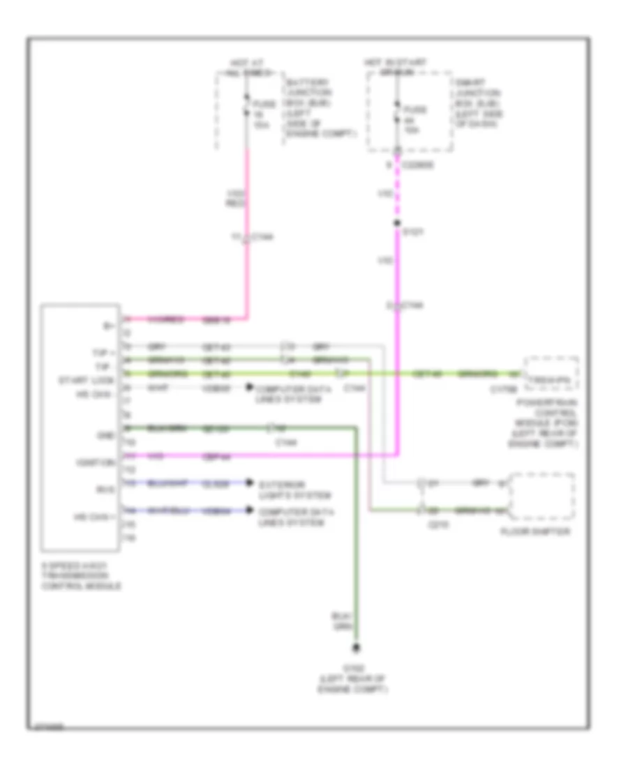
- (3.5l) 6 speed transmission
- (3.5l: near breakout to abs module) (2.5l & 3.0l: near breakout to to ambient air temperature sensor) s162
- (3.5l: near breakout to powertrain control module) (w/ hid) s104
- (left side of dash) g202
- (near breakout to c144) s122
- (near breakout to c144) s123
- (near breakout to c212) s220
- (near breakout to c3047) s336
- (near breakout to g201) s225
- (near breakout to g301) s334
- (near breakout to pscm)
- (not used) (2.5l/3.0l)
- 2.5l/3.0l
- 3.5l
- 4x4 control module (left side of dash)
- Anti-lock brake system (abs) module (right front of engine compt)
- C1010
- C139
- C144
- C175b
- C215
- C219
- C2280a
- C2280b
- C237
- C3047
- C310b
- C312
- Cdb08
- Data link connector (dlc) (left side of dash)
- Feps
- Fuse 15a
- Gd116
- Headlamp control module (w/ hid) (left rear of engine compt)
- Hot at all times
- Hs can+
- Hs can+ c1467b
- Hs can-
- Hs can- c175b
- Instrument panel cluster (ipc)
- Ms can+
- Ms can-
- Occupant classification system module (ocsm) (under right front seat cushion)
- Power steering control module (pscm) (right side of engine compt, near strut tower)
- Powertrain control module (pcm) (left rear of engine compt)
- Restraints control module (rcm) (under center console)
- S103 (w/ hid)
- S105 (near breakout to pscm)
- S106
- S161 (3.5l: near breakout to abs module) (2.5l & 3.0l: near breakout to to ambient air temperature sensor)
- S221 (near breakout to c212)
- S226 (near breakout to data link connector)
- S332
- S350
- S351
- Sbp20
- Smart junction box (sjb) (left side of dash)
- Vdb04
- Vdb05
- Vdb06
- Vdb07
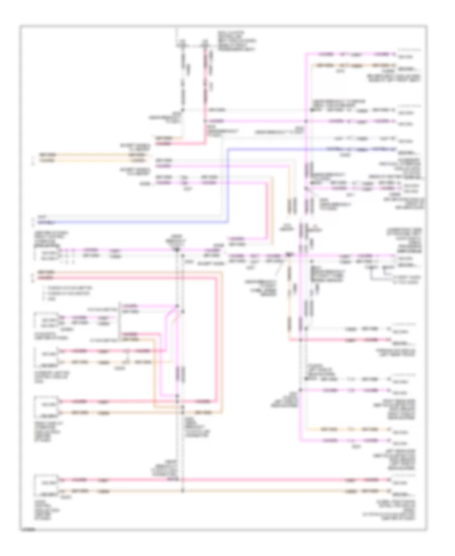
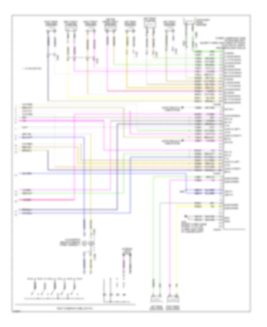
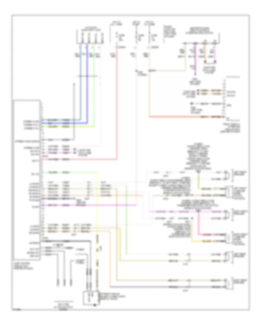
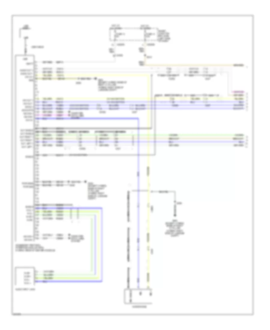
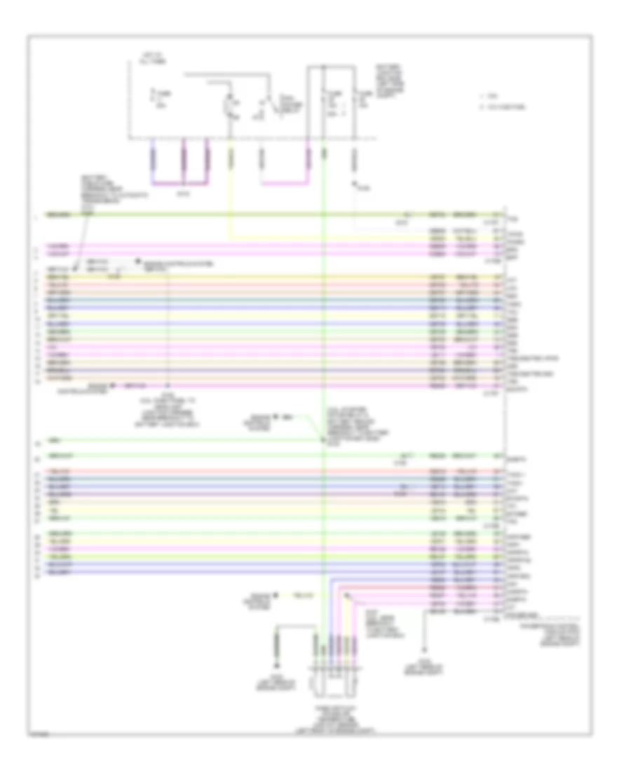
Computer Data Lines Wiring Diagram, Except Hybrid (2 of 2) for Ford Fusion S 2012
List of elements for Computer Data Lines Wiring Diagram, Except Hybrid (2 of 2) for Ford Fusion S 2012:
- (center of dash) front control interface module (fcim)
- (license jumper harness, left side of rear bumper) s442
- (near breakout to c211) s222
- (near breakout to data link connector) s227
- (near breakout to smart junction box (sjb)) s353
- (right front of trunk) audio digital signal processing (dsp) module
- Accessory protocol interface module (apim) (w/ sync)
- Audio control module (acm) (center of dash)
- Base
- C2238
- C2356a
- C2357a
- C237
- C240c
- C3050
- C3052
- C312
- C316
- C3305c vdb07
- C406
- C4253c
- C511
- Driver door module (front of driver's door)
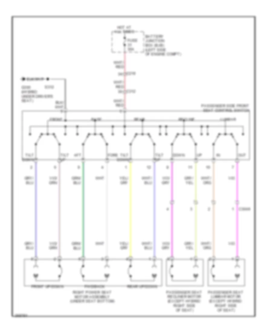
- Driver seat module (dsm) (under driver's seat)
- Dual climate controlled seat module (dcsm) (under right front seat cushion)
- Except base
- Except base & w/ memory
- Except base & w/o memory
- Front display interface module (fdim) (center of dash)
- Fusion w/ navigation
- Fusion w/o navigation
- Global positioning satellite module (gpsm) (w/ sync w/o navigation) (left side of dash)
- Hs can+
- Hs can-
- Hvac-datc (automatic a/c) (center of dash)
- Hvac-emtc (manual a/c) (center of dash)
- Interior lighting control module (mkz)
- Left rear side obstacle detection (sod) sensor (left side of rear bumper)
- Mkz w/ navigation
- Ms can+
- Ms can+ c3299d
- Ms can+ c4240c
- Ms can+ c568b
- Ms can-
- Parking aid module (left rear of trunk)
- Right rear side obstacle detection (sod) sensor (right side of rear bumper)
- S223
- S228
- S342
- S343
- S345 (near breakout to g301)
- S346
- S352
- S430 (near breakout to right wheel speed sensor)
- S431 (near breakout to right wheel speed sensor)
- S441 (left side of rear bumper)
- Vdb04
- Vdb05
- Vdb06
- Vdb07
- W/ memory
- W/ navigation
- W/ sony audio
- W/ thx audio
- W/o memory
- W/o navigation
Computer Data Lines Wiring Diagram, Hybrid (1 of 2) for Ford Fusion S 2012
List of elements for Computer Data Lines Wiring Diagram, Hybrid (1 of 2) for Ford Fusion S 2012:
- (left side of dash) g202
- (near breakout to battery junction box) s199
- (near breakout to c145) s162
- (near breakout to c220)
- (near breakout to c810) s336
- (near breakout to g201) s225
- (near breakout to g301)
- (near breakout to g301) s334
- (near breakout to pscm) s106
- (under center console) restraints control module (rcm)
- (w/ hid) headlamp control module (hcm)
- Air conditioning compressor module (accm) (left front of engine)
- Anti-lock brake system (abs) control module (right rear of engine compt)
- Battery energy control module (becm) (behind left side of rear seat)
- C1010
- C133
- C215
- C2280a
- C2280b
- C237
- C310b
- C312
- C4237a
- Cdb08
- Data link connector (dlc) (left side of dash)
- Dc/dc converter module
- Feps
- Fuse 15a
- Gd116
- Hot at all times
- Hs can+
- Hs can+ c1457d
- Hs can+ c1458a
- Hs can+ c1467b
- Hs can+ c1469a
- Hs can-
- Hs can- c175b
- Instrument panel cluster (ipc)
- Ms can+
- Ms can-
- Occupant classification system module (ocsm) (under right front seat cushion)
- Power steering control module (pscm) (right side of engine compt, near strut tower)
- Powertrain control module (pcm) (left rear of engine compt)
- S103 (w/ hid) (near breakout to powertrain control module)
- S105 (near breakout to pscm)
- S161 (near breakout to c145)
- S196 (near breakout to ambient air temperature sensor)
- S197
- S198 (near breakout to battery junction box)
- S220 (near breakout to hazard flasher switch)
- S226 (near breakout to data link connector)
- S333 (near breakout to c312)
- Sbp20
- Smart junction box (sjb) (left side of dash)
- Transaxle control module (on transaxle)
- Vdb04
- Vdb05
- Vdb06
- Vdb07
Computer Data Lines Wiring Diagram, Hybrid (2 of 2) for Ford Fusion S 2012
List of elements for Computer Data Lines Wiring Diagram, Hybrid (2 of 2) for Ford Fusion S 2012:
- (center of dash) front control interface module (fcim)
- (fusion: left side of rear bumper) s442
- (near breakout to brake pedal angle sensor) s343
- (near breakout to c211) s222
- (near breakout to c3053) s353
- (near breakout to data link connector) s227
- (near breakout to right wheel speed sensor)
- (under right side of package tray) audio digital signal processing (dsp) module
- Accessory protocol interface module (apim) (w/ sync) (rear of center console)
- Audio control module (acm) (center of dash)
- Base
- C2238
- C2356a
- C237
- C240c
- C3050
- C3052
- C312
- C316
- C3305c vdb07
- C406
- C4253c
- C511
- Driver door module (front of driver's door)
- Driver's seat module (dsm) (base of left front seat)
- Dual climate controlled seat module (dcsm) (base of front passenger's seat)
- Except base
- Except base & w/ memory
- Except base & w/o memory
- Front display interface module (fdim) (center of dash)
- Fusion w/ navigation
- Fusion w/o navigation
- Global positioning satellite module (gpsm) (w/ sync & w/o navigation) (center of dash)
- Hs can+
- Hs can-
- Hvac-datc (center of dash)
- Interior lighting control module (mkz)
- Left rear side obstacle detection (sod) sensor (left side of rear bumper)
- Mkz
- Ms can+
- Ms can+ c3299d
- Ms can+ c4240c
- Ms can-
- Ms can- c568b
- Parking aid module (left rear trunk)
- Right rear side obstacle detection (sod) sensor (right side of rear bumper)
- S223
- S228 (near breakout to data link connector)
- S342 (near breakout to c327)
- S345 (near breakout to g301)
- S346 (near breakout to g301)
- S352 (near breakout to c3053)
- S430
- S431 (near breakout to right wheel speed sensor)
- S441 (fusion: left side of rear bumper)
- Vdb04
- Vdb05
- Vdb06
- Vdb07
- W/ memory
- W/ navigation
- W/ sony audio
- W/ thx audio
- W/o memory
- W/o navigation
COOLING FAN
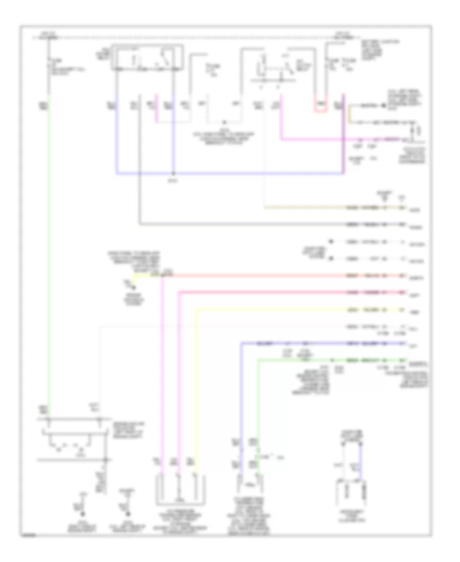
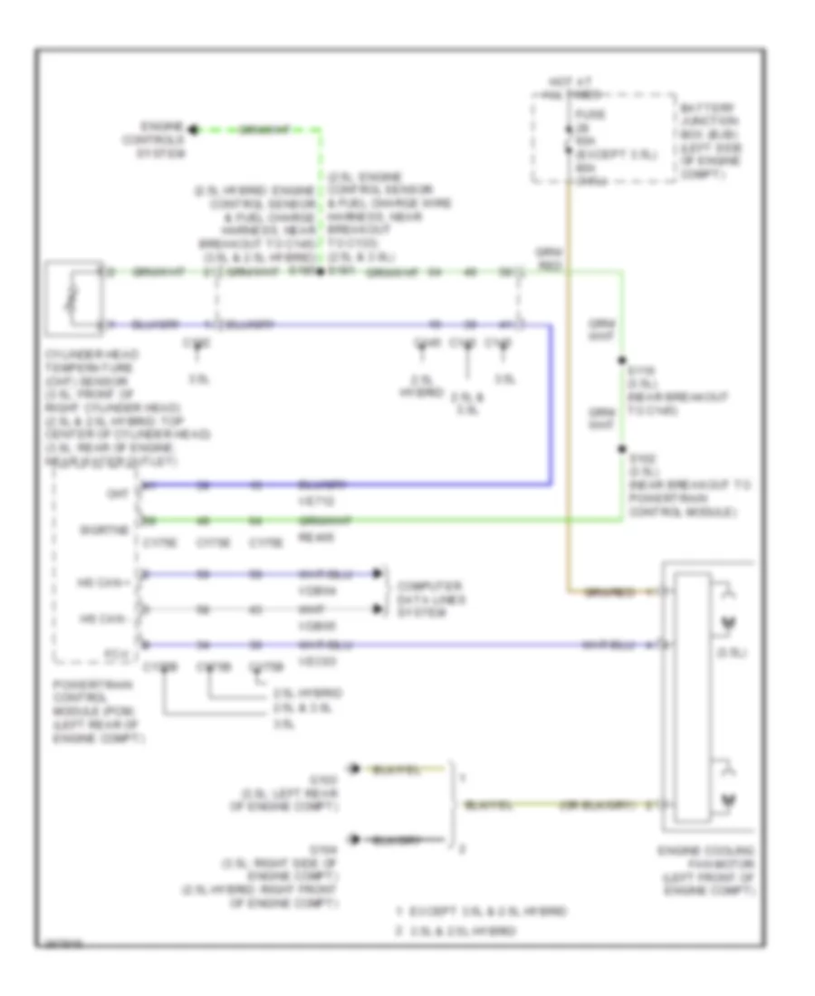
Cooling Fan Wiring Diagram for Ford Fusion S 2012
List of elements for Cooling Fan Wiring Diagram for Ford Fusion S 2012:
- & fuel charge wire harness, near breakout to c133) (2.5l & 3.0l) s181
- (2.5l: engine control sensor (2.5l hybrid: engine control sensor & fuel charge harness, near breakout to c145) (3.5l & 2.5l hybrid) s180
- (3.5l)
- 2.5l & 3.0l
- 2.5l hybrid
- 3.5l
- 3.5l & 2.5l hybrid
- Battery junction box (bjb) (left side of engine compt)
- C145
- C175b
- C175e
- C192
- Cht
- Computer data lines system
- Cylinder head temperature (cht) sensor (3.5l: front of right cylinder head) (2.5l & 2.5l hybrid: top center of cylinder head) (3.0l: rear of engine, near water outlet)
- Engine controls system
- Engine cooling fan motor (left front of engine compt)
- Except 3.5l & 2.5l hybrid
- Fc-v
- Fuse 60a (except 3.5l) 80a (3.5l)
- G103 (3.0l: left rear of engine compt)
- G104 (3.5l: right side of engine compt) (2.5l hybrid: right front of engine compt)
- Hot at all times
- Hs can +
- Hs can -
- Powertrain control module (pcm) (left rear of engine compt)
- Re405
- S102 (3.5l) (near breakout to powertrain control module)
- Sigrtne
- Vdb04
- Vdb05
- Ve712
- Vec03
CRUISE CONTROL
2.5L
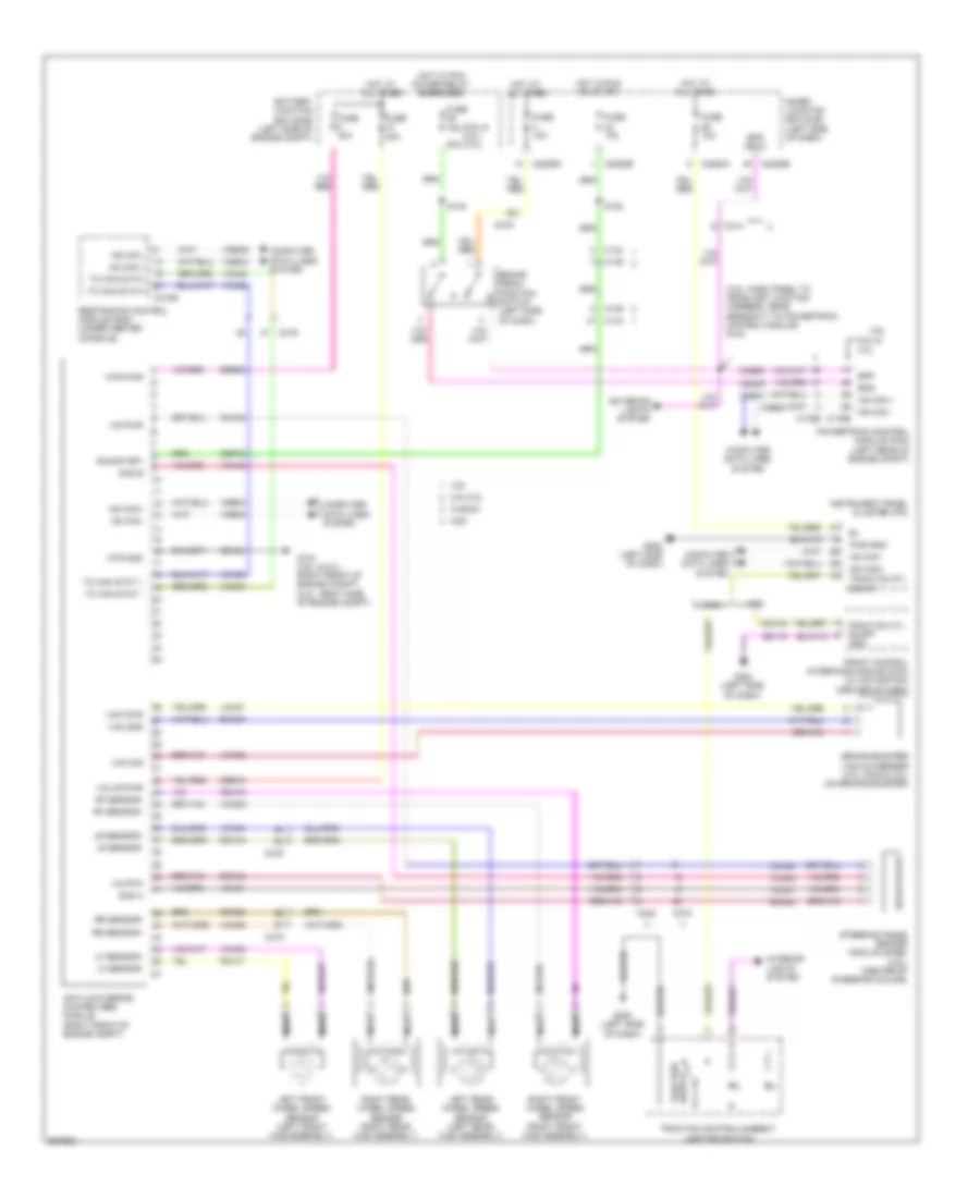
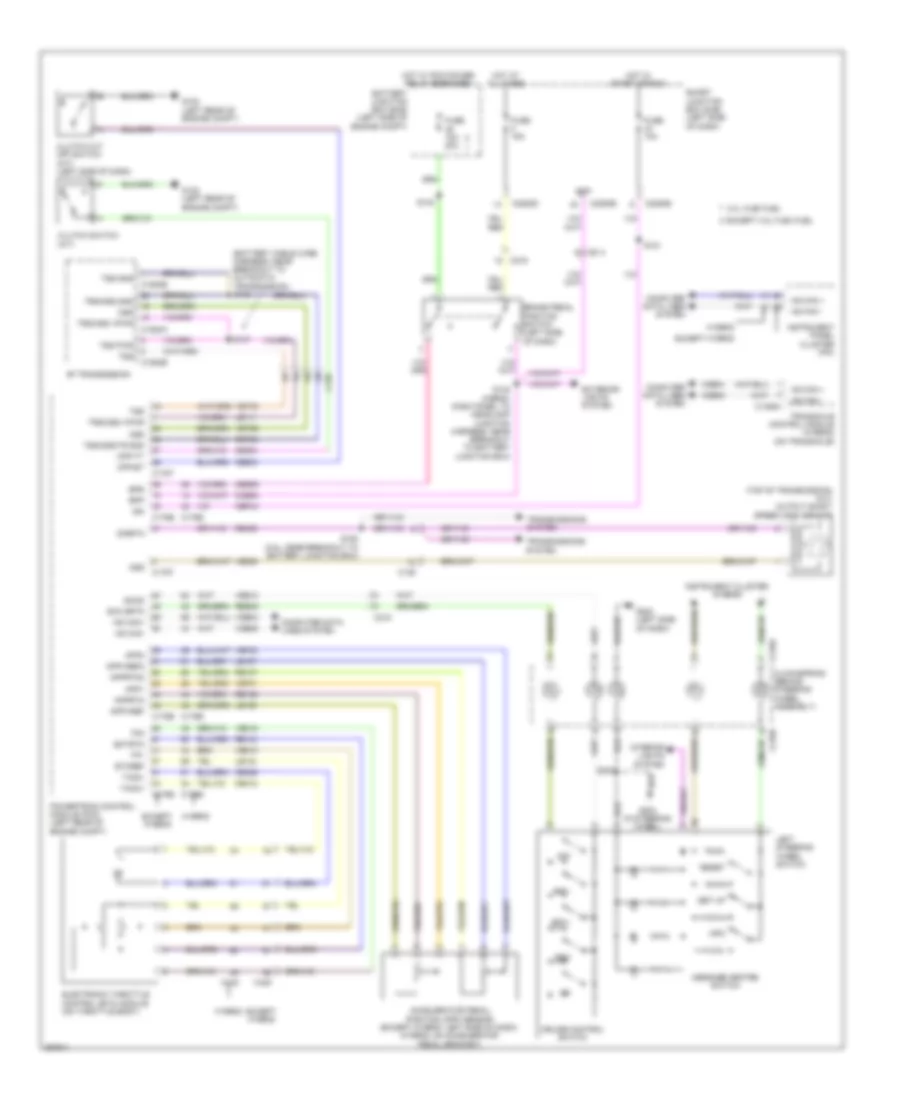
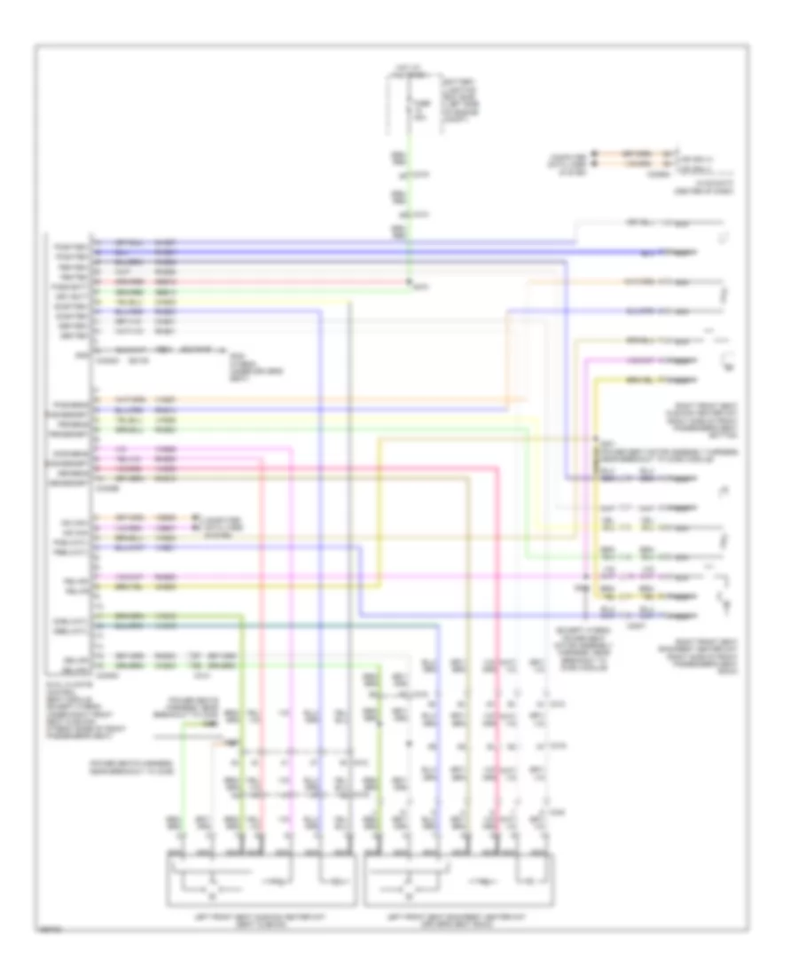
2.5L, Cruise Control Wiring Diagram for Ford Fusion S 2012
List of elements for 2.5L, Cruise Control Wiring Diagram for Ford Fusion S 2012:
- (battery cable wire harness, near breakout to automatic transmission) s146
- (top of transmission) (m/t) output shaft speed (oss) sensor
- 3.0l flex fuel
- 6f transmission
- Accelerator pedal position (app) sensor (except hybrid: left side of dash) (hybrid: on accelerator pedal bracket)
- App1
- App2
- Apprtn
- Apprtn2
- Appvref
- Appvref2
- Battery junction box (bjb) (left side of engine compt)
- Bpp
- Bps
- Brake pedal position switch (left side of dash)
- C139
- C145
- C1458a
- C1520a
- C1520b
- C175b
- C175e
- C175t
- C214
- C215
- C218a
- C218b
- C219
- C2280b
- C2280d
- C2280e
- Cbp44
- Ccb08
- Ce412
- Ce426
- Ce903
- Ce904
- Ces09
- Clockspring (behind steering wheel assembly)
- Clutch cut off switch (m/t) (left side of dash)
- Clutch switch (m/t)
- Computer data lines system
- Cpp-bt
- Cpp-tt
- Cruise control switch
- Ectrtn
- Electronic throttle control (etc) module (on throttle body)
- Etcref
- Except 3.0l flex fuel
- Except hybrid
- Exterior lights system
- Fuse 10a
- Fuse 15a
- Fuse 15a 20a
- G102 (left rear of engine compt)
- G202 (left side of dash)
- G204 (in steering wheel)
- Hot at all times
- Hot in start or run
- Hot w/ pcm power relay energized
- Hs can +
- Hs can -
- Hs can+
- Hs can-
- Hybrid
- Ign
- Info
- Instrument cluster system
- Instrument panel cluster (ipc)
- Interior lights system
- Le111
- Le134
- Le136
- Le137
- Left steering wheel switch
- Message centre switch
- Off
- Oss
- Powertrain control module (pcm) (left rear of engine compt)
- Re134
- Re136
- Re137
- Re406
- Res08
- Reset
- Ret24
- Rsm
- S121
- S140
- S142 (hibrid: dash panel to headlamp junction harness, near breakout to battery junction box)
- S147
- S182 (2.5l: near breakout to battery junction box)
- S203
- Scc srtn
- Sccs
- Set up
- Set+
- Set-
- Sigrtn
- Smart junction box (sjb) (left side of dash)
- Tacm+
- Tacm-
- Tp1
- Tp2
- Transaxle control module (hybrid) (on transaxle)
- Transmissions system
- Trs/oss gnd
- Trs/oss vpwr
- Tss
- Tss gnd
- Tss pwr
- Tss/oss/tr gnd
- Vdb04
- Vdb05
- Ve701
- Ve702
- Ve806
- Ve818
- Ve819
- Ves10
- Vet26
- Vet33
2.5L HYBRID
2.5L Hybrid, Cruise Control Wiring Diagram for Ford Fusion S 2012
List of elements for 2.5L Hybrid, Cruise Control Wiring Diagram for Ford Fusion S 2012:
- (battery cable wire harness, near breakout to automatic transmission) s146
- (top of transmission) (m/t) output shaft speed (oss) sensor
- 3.0l flex fuel
- 6f transmission
- Accelerator pedal position (app) sensor (except hybrid: left side of dash) (hybrid: on accelerator pedal bracket)
- App1
- App2
- Apprtn
- Apprtn2
- Appvref
- Appvref2
- Battery junction box (bjb) (left side of engine compt)
- Bpp
- Bps
- Brake pedal position switch (left side of dash)
- C139
- C145
- C1458a
- C1520a
- C1520b
- C175b
- C175e
- C175t
- C214
- C215
- C218a
- C218b
- C219
- C2280b
- C2280d
- C2280e
- Cbp44
- Ccb08
- Ce412
- Ce426
- Ce903
- Ce904
- Ces09
- Clockspring (behind steering wheel assembly)
- Clutch cut off switch (m/t) (left side of dash)
- Clutch switch (m/t)
- Computer data lines system
- Cpp-bt
- Cpp-tt
- Cruise control switch
- Ectrtn
- Electronic throttle control (etc) module (on throttle body)
- Etcref
- Except 3.0l flex fuel
- Except hybrid
- Exterior lights system
- Fuse 10a
- Fuse 15a
- Fuse 15a 20a
- G102 (left rear of engine compt)
- G202 (left side of dash)
- G204 (in steering wheel)
- Hot at all times
- Hot in start or run
- Hot w/ pcm power relay energized
- Hs can +
- Hs can -
- Hs can+
- Hs can-
- Hybrid
- Ign
- Info
- Instrument cluster system
- Instrument panel cluster (ipc)
- Interior lights system
- Le111
- Le134
- Le136
- Le137
- Left steering wheel switch
- Message centre switch
- Off
- Oss
- Powertrain control module (pcm) (left rear of engine compt)
- Re134
- Re136
- Re137
- Re406
- Res08
- Reset
- Ret24
- Rsm
- S121
- S140
- S142 (hibrid: dash panel to headlamp junction harness, near breakout to battery junction box)
- S147
- S182 (2.5l: near breakout to battery junction box)
- S203
- Scc srtn
- Sccs
- Set up
- Set+
- Set-
- Sigrtn
- Smart junction box (sjb) (left side of dash)
- Tacm+
- Tacm-
- Tp1
- Tp2
- Transaxle control module (hybrid) (on transaxle)
- Transmissions system
- Trs/oss gnd
- Trs/oss vpwr
- Tss
- Tss gnd
- Tss pwr
- Tss/oss/tr gnd
- Vdb04
- Vdb05
- Ve701
- Ve702
- Ve806
- Ve818
- Ve819
- Ves10
- Vet26
- Vet33
3.0L FLEX FUEL
3.0L Flex Fuel, Cruise Control Wiring Diagram for Ford Fusion S 2012
List of elements for 3.0L Flex Fuel, Cruise Control Wiring Diagram for Ford Fusion S 2012:
- (battery cable wire harness, near breakout to automatic transmission) s146
- (top of transmission) (m/t) output shaft speed (oss) sensor
- 3.0l flex fuel
- 6f transmission
- Accelerator pedal position (app) sensor (except hybrid: left side of dash) (hybrid: on accelerator pedal bracket)
- App1
- App2
- Apprtn
- Apprtn2
- Appvref
- Appvref2
- Battery junction box (bjb) (left side of engine compt)
- Bpp
- Bps
- Brake pedal position switch (left side of dash)
- C139
- C145
- C1458a
- C1520a
- C1520b
- C175b
- C175e
- C175t
- C214
- C215
- C218a
- C218b
- C219
- C2280b
- C2280d
- C2280e
- Cbp44
- Ccb08
- Ce412
- Ce426
- Ce903
- Ce904
- Ces09
- Clockspring (behind steering wheel assembly)
- Clutch cut off switch (m/t) (left side of dash)
- Clutch switch (m/t)
- Computer data lines system
- Cpp-bt
- Cpp-tt
- Cruise control switch
- Ectrtn
- Electronic throttle control (etc) module (on throttle body)
- Etcref
- Except 3.0l flex fuel
- Except hybrid
- Exterior lights system
- Fuse 10a
- Fuse 15a
- Fuse 15a 20a
- G102 (left rear of engine compt)
- G202 (left side of dash)
- G204 (in steering wheel)
- Hot at all times
- Hot in start or run
- Hot w/ pcm power relay energized
- Hs can +
- Hs can -
- Hs can+
- Hs can-
- Hybrid
- Ign
- Info
- Instrument cluster system
- Instrument panel cluster (ipc)
- Interior lights system
- Le111
- Le134
- Le136
- Le137
- Left steering wheel switch
- Message centre switch
- Off
- Oss
- Powertrain control module (pcm) (left rear of engine compt)
- Re134
- Re136
- Re137
- Re406
- Res08
- Reset
- Ret24
- Rsm
- S121
- S140
- S142 (hibrid: dash panel to headlamp junction harness, near breakout to battery junction box)
- S147
- S182 (2.5l: near breakout to battery junction box)
- S203
- Scc srtn
- Sccs
- Set up
- Set+
- Set-
- Sigrtn
- Smart junction box (sjb) (left side of dash)
- Tacm+
- Tacm-
- Tp1
- Tp2
- Transaxle control module (hybrid) (on transaxle)
- Transmissions system
- Trs/oss gnd
- Trs/oss vpwr
- Tss
- Tss gnd
- Tss pwr
- Tss/oss/tr gnd
- Vdb04
- Vdb05
- Ve701
- Ve702
- Ve806
- Ve818
- Ve819
- Ves10
- Vet26
- Vet33
3.5L
3.5L, Cruise Control Wiring Diagram for Ford Fusion S 2012
List of elements for 3.5L, Cruise Control Wiring Diagram for Ford Fusion S 2012:
- 6 speed aw21 transmission control module (tcm)
- Accelerator pedal position sensor (left side of dash)
- App1
- App2
- App3
- Apprtn
- Apprtn2
- Appvref
- Appvref2
- Battery junction box (bjb) (left side of engine compt)
- Bpp
- Bps
- Brake pedal position switch (left side of dash)
- C145
- C175b
- C175e
- C214
- C215
- C218a
- C218b
- C219
- C2280b
- C2280d
- C2280e
- Cbp44
- Ccb08
- Ce412
- Ce426
- Ces09
- Clock- spring (behind steering wheel assembly)
- Computer data lines system
- Cruise control switch
- Ectrtn
- Electronic throttle control (etc) module (on throttle body)
- Etcref
- Exterior lights system
- Fuse 10a
- Fuse 15a
- G202 (left side of dash)
- G204 (in steering wheel)
- Hot at all times
- Hot in start or run
- Hot w/ pcm power relay energized
- Hs can +
- Hs can -
- Hs can+
- Hs can-
- Ign
- Info
- Instrument cluster system
- Instrument panel cluster (ipc)
- Interior lights system
- Le134
- Le136
- Le137
- Left steering wheel switch
- Message center switch
- Off
- Powertrain control module (pcm) (left rear of engine compt)
- Re134
- Re136
- Re137
- Res08
- Reset
- Rsm
- S121
- S140
- S142 (dash panel to headlamp junction harness, near breakout to powertrain control module)
- S203
- Scc srtn
- Sccs
- Set up
- Set+
- Set-
- Smart junction box (sjb) (left side of dash)
- Tacm+
- Tacm-
- Tp1
- Tp2
- Vdb04
- Vdb05
- Ve701
- Ve702
- Ve703
- Ve818
- Ve819
- Ves10
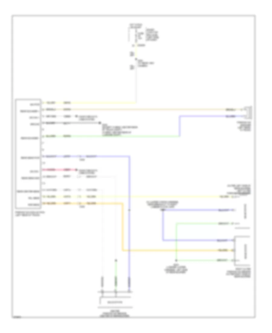
DEFOGGERS
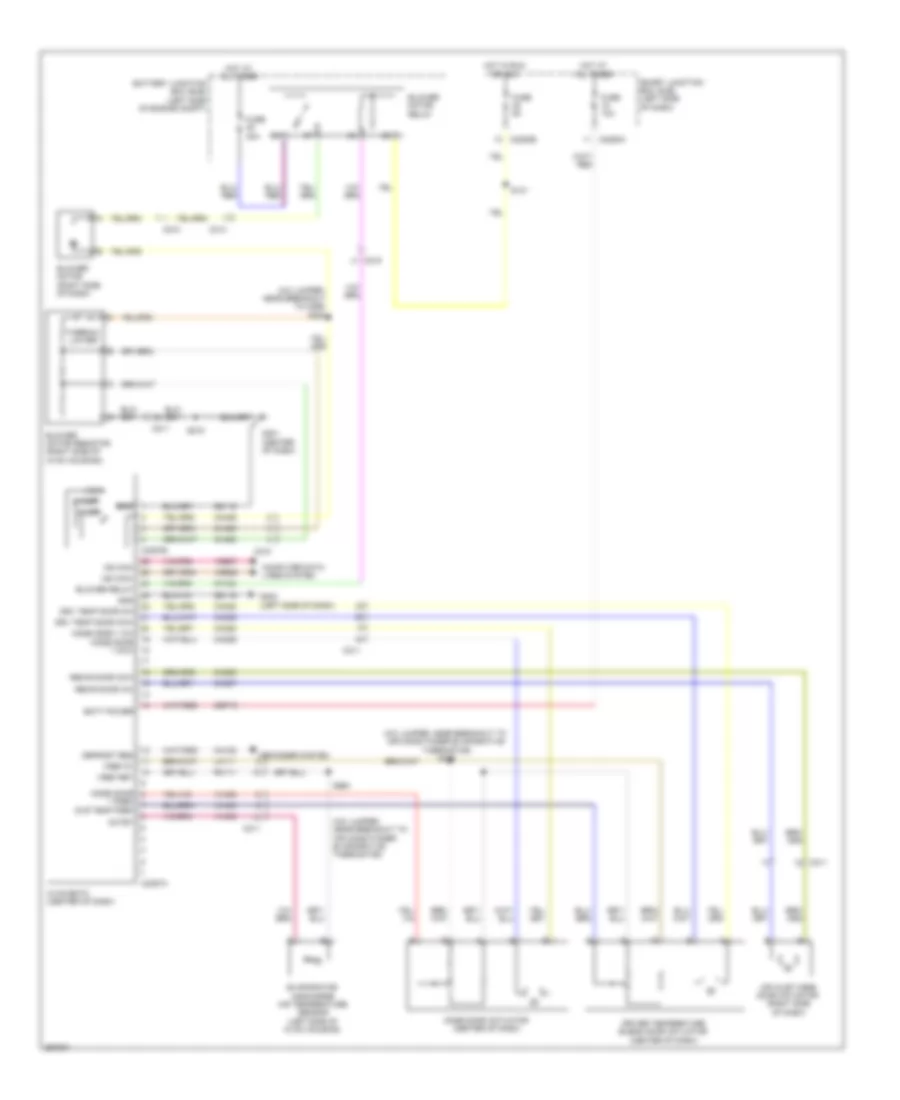
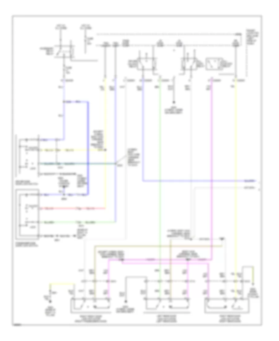
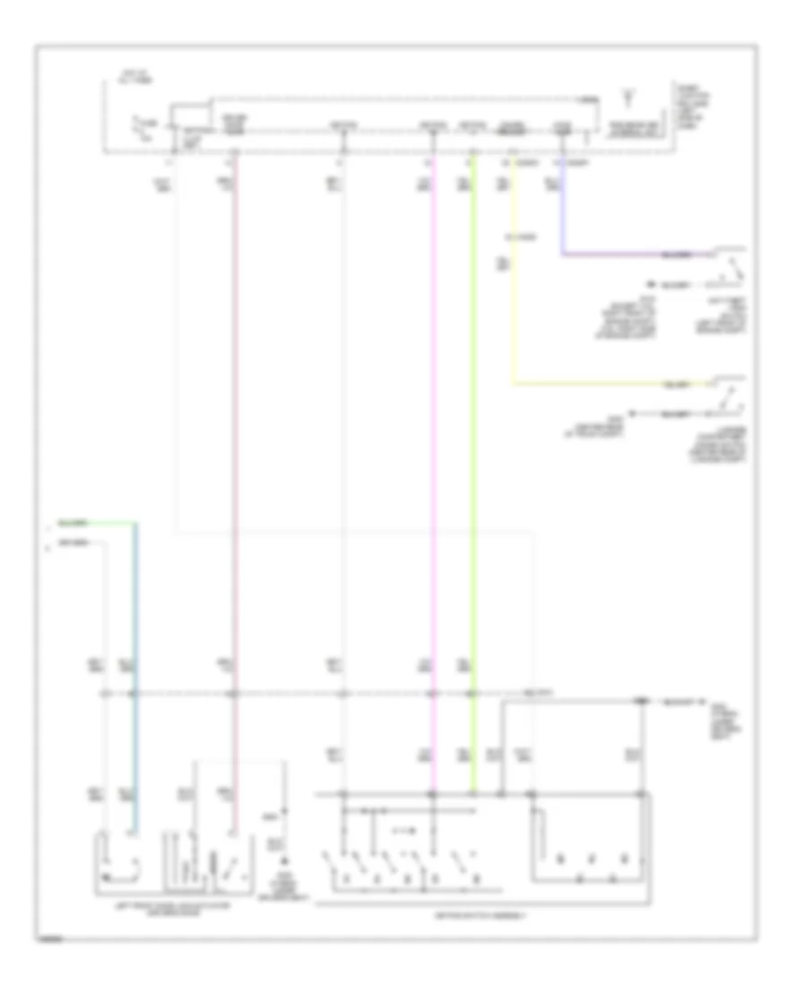
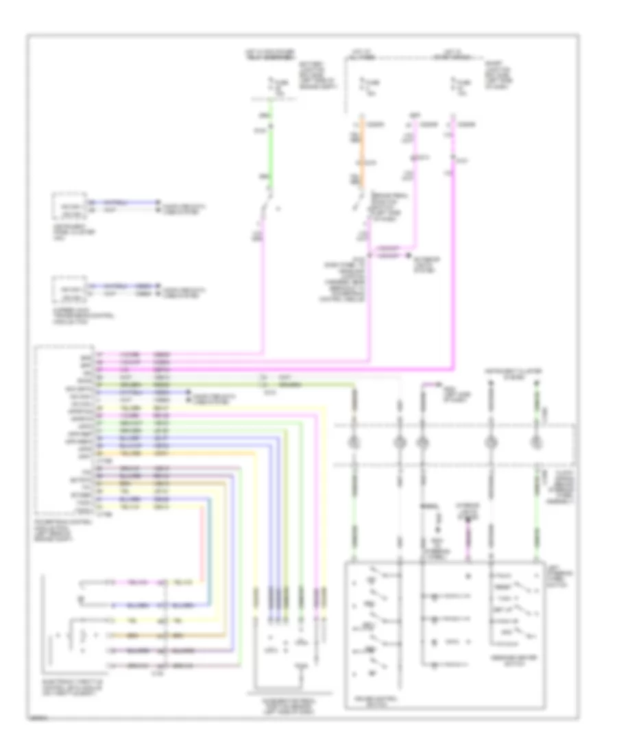
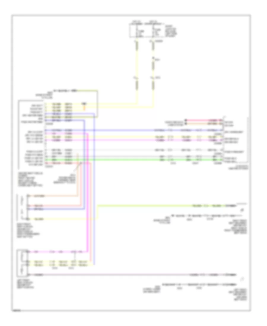
Defoggers Wiring Diagram for Ford Fusion S 2012
List of elements for Defoggers Wiring Diagram for Ford Fusion S 2012:
- (except hybrid: power seats harness, near breakout to smart junction box (sjb)) (hybrid: body main harness, near breakout to g300) s322
- Antenna module (except hybrid: right rear of trunk)
- Automatic a/c
- Battery junction box (bjb) (left side of engine compt)
- C215
- C219
- C2280e
- C2356a
- C2357a
- C402a
- C402b
- C4194b
- C510
- C511
- C610
- Dash)
- Def pwr
- Defrost relay
- Defrost request
- Except hybrid
- Fuse 10a
- Fuse 40a
- Fuse 5a
- Fusion
- G203 (base of right "a" pillar)
- G300 (hybrid: under driver's seat)
- G405 (left side of rear window)
- Hot at all times
- Hot in run or acc
- Hvac module (datc) (center of dash)
- Hvac module (emtc) (center of dash)
- Hybrid
- Left side exterior rear view mirror
- Manual a/c
- Mkz
- Rear window defrost grid
- Right side exterior rear view mirror
- S131
- S175 (hybrid: dash panel to headlamp junction harness, near breakout to battery junction box)
- S480 (hybrid)
- S500
- S601
- Smart junction box (sjb) (left side of
ELECTRONIC POWER STEERING
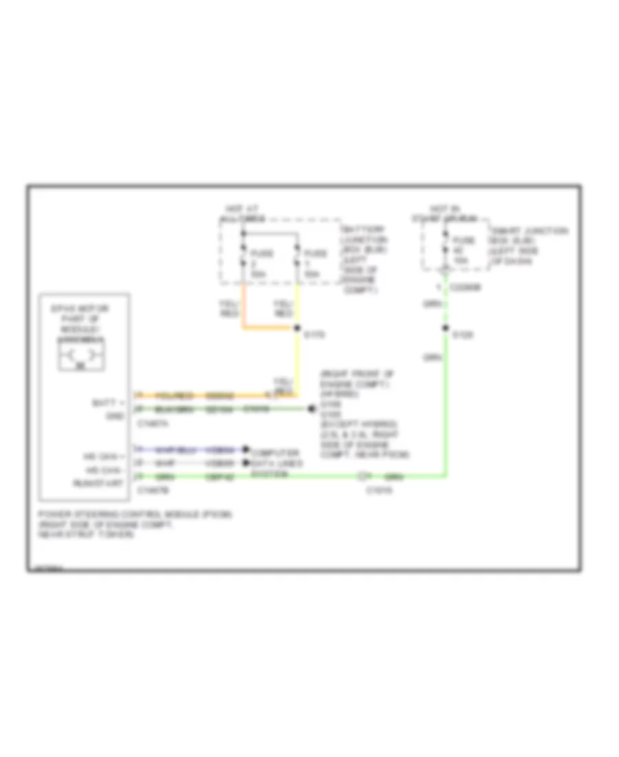
Electronic Power Steering Wiring Diagram for Ford Fusion S 2012
List of elements for Electronic Power Steering Wiring Diagram for Ford Fusion S 2012:
- (right front of engine compt) (hybrid) g106 g105 (except hybrid) (2.5l & 3.0l: right side of engine compt, near pscm)
- Batt +
- Battery junction box (bjb) (left side of engine compt)
- C1010
- C1019
- C1467a
- C1467b
- C2280b
- Cbp42
- Computer data lines system
- Epas motor part of module/ assembly
- Fuse 10a
- Fuse 50a
- Gd104
- Gnd
- Hot at all times
- Hot in start or run
- Hs can +
- Hs can -
- Power steering control module (pscm) (right side of engine compt, near strut tower)
- Run/start
- S120
- S170
- Sbb02
- Smart junction box (sjb) (left side of dash)
- Vdb04
- Vdb05
ENGINE PERFORMANCE
2.5L
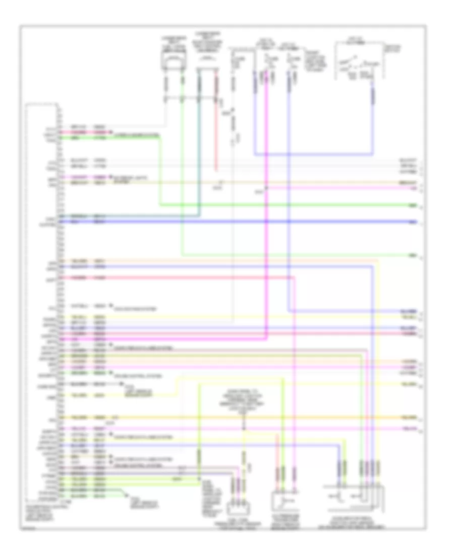
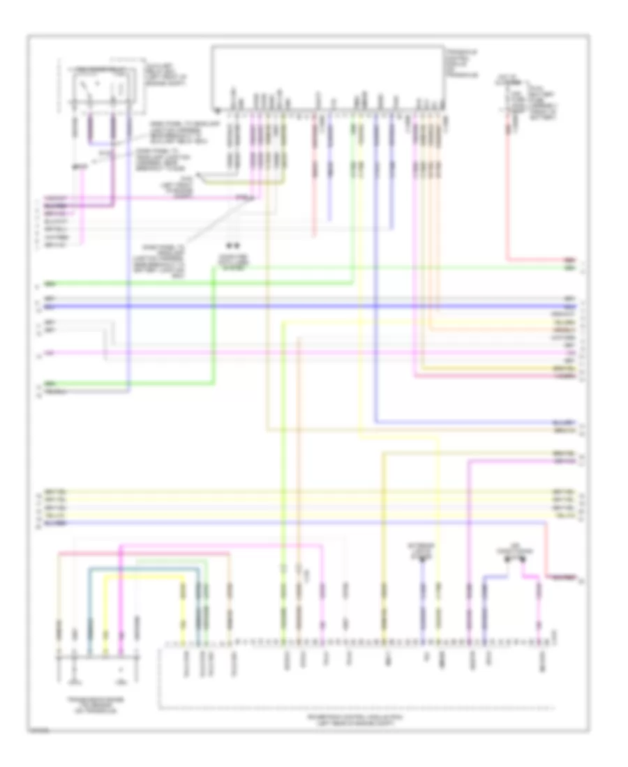
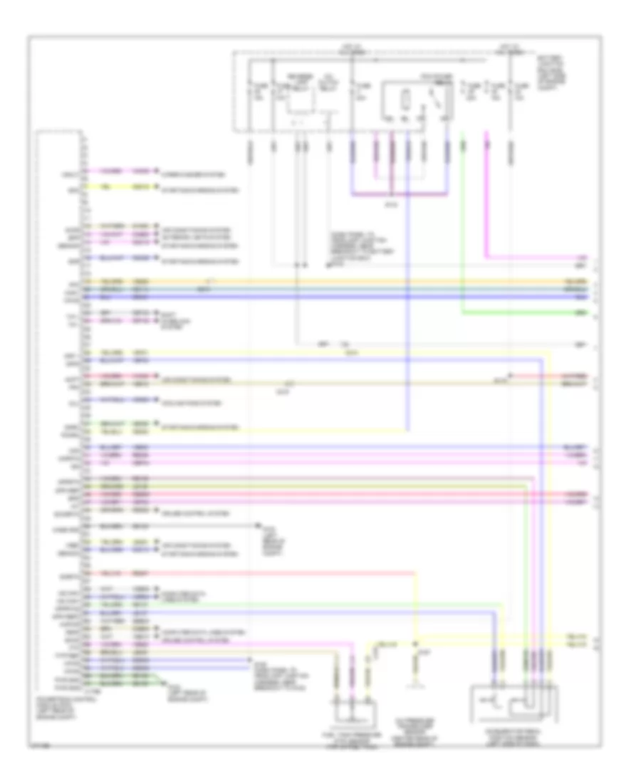
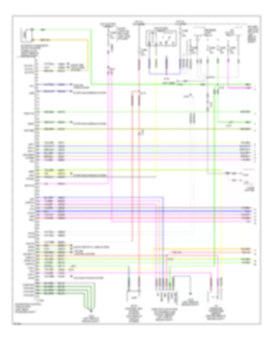
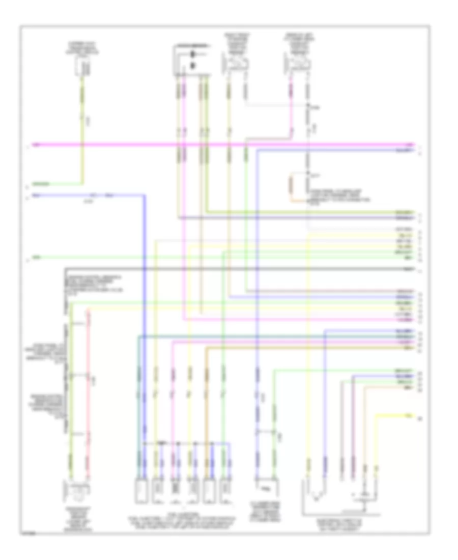
2.5L, Engine Performance Wiring Diagram (1 of 5) for Ford Fusion S 2012
List of elements for 2.5L, Engine Performance Wiring Diagram (1 of 5) for Ford Fusion S 2012:
- (m/t)
- 10a
- 15a
- 40a
- A/c clutch relay
- A/c pressure transducer sensor (right front of engine)
- Accelerator pedal position (app) sensor (left side of dash)
- Accr
- Acpt
- Air conditioning system
- App1
- App2
- Apprtn
- Apprtn2
- Appvref
- Appvrref2
- Battery junction box (bjb) (left side of engine compt)
- Bpp
- Bps
- C133
- C175b
- C214
- C215
- C219
- Canv
- Case gnd
- Cbb46
- Cbk01
- Cbk02
- Cbp44
- Ccb08
- Cdb08
- Cdc10
- Cdc12
- Cdc15
- Cdc35
- Ce114
- Ce302
- Ce336
- Ces09
- Cet42
- Cet43
- Ch302
- Computer data lines system
- Cooling fans system
- Cruise control system
- Exterior lights system
- Fcv
- Feps
- Floor shifter
- Fpc
- Fpm
- Ftp
- Ftpref
- Fuel tank pressure (ftp) sensor (top of fuel tank)
- Fuse
- G102 (left rear of engine compt)
- Gd120
- Gencom
- Genmon
- Hot at all times
- Hs can+
- Hs can-
- Iat
- Ign
- Kapwr
- Le136
- Le137
- Le230
- Le424
- Maf
- Mafrtn
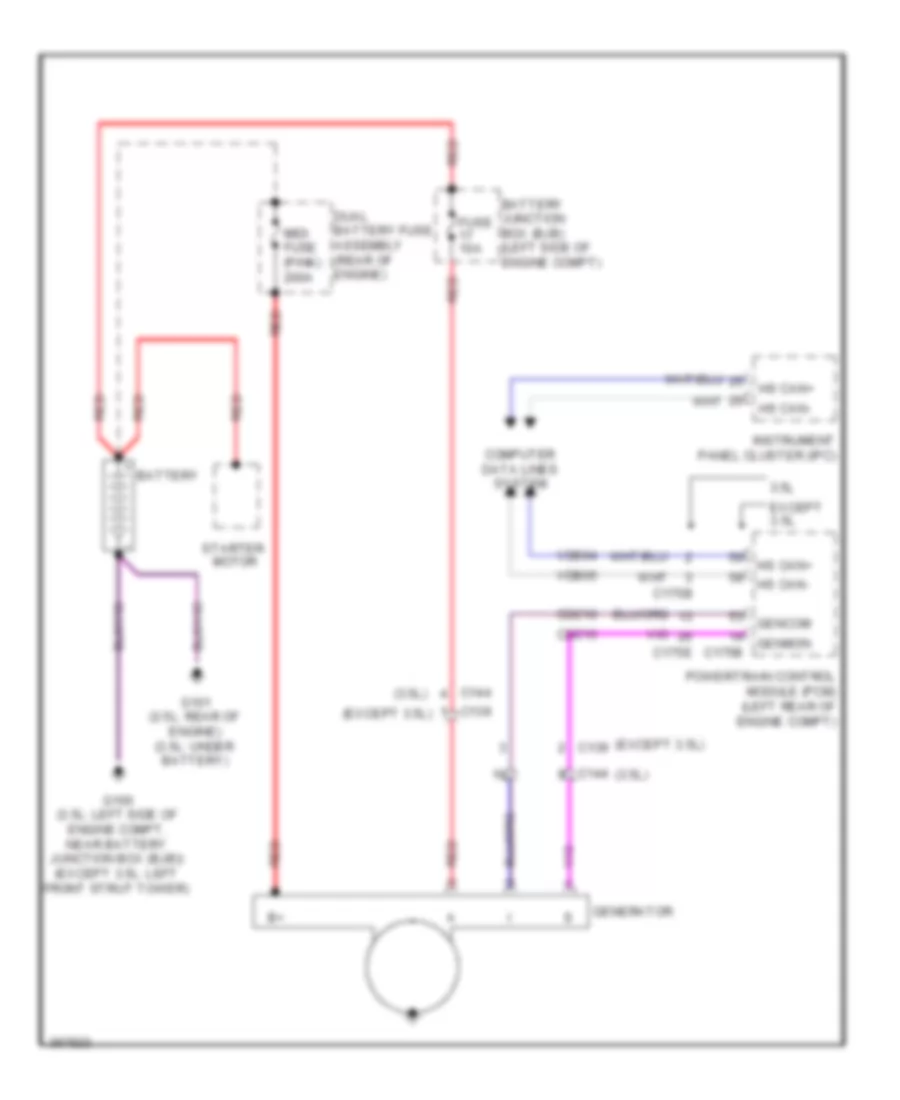
- Pcm power relay
- Pcmrc
- Power gnd
- Powertrain control module (pcm) (left rear of engine compt)
- Re136
- Re137
- Re325
- Re407
- Res08
- Reverse lamp relay
- S119
- S125
- S143
- S144
- S251
- Sbb23
- Sccs
- Sccsrtn
- Shift interlock system
- Sigrtn
- Smc
- Smr
- Smrc
- Starting/charging system
- Tip +
- Tip -
- Transmission control switch
- Vce03
- Vdb04
- Vdb05
- Ve225
- Ve518
- Ve701
- Ve702
- Ve740
- Ve808
- Ve922
- Ves10
- Vh433
- Vmc05
- Vpwr
- Vpwrtr-pn
- Vref
- Vsout
- Wiper/washer system
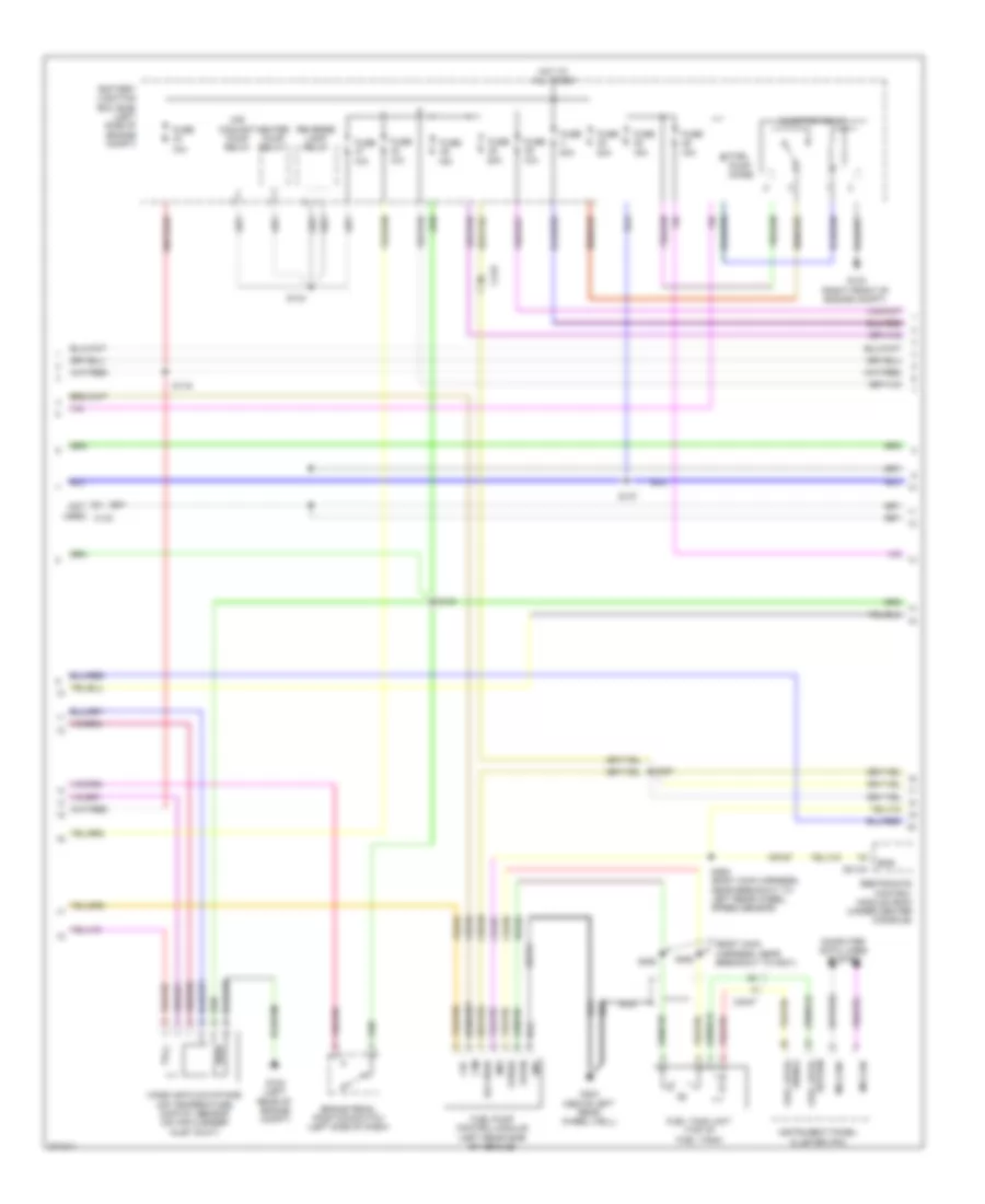
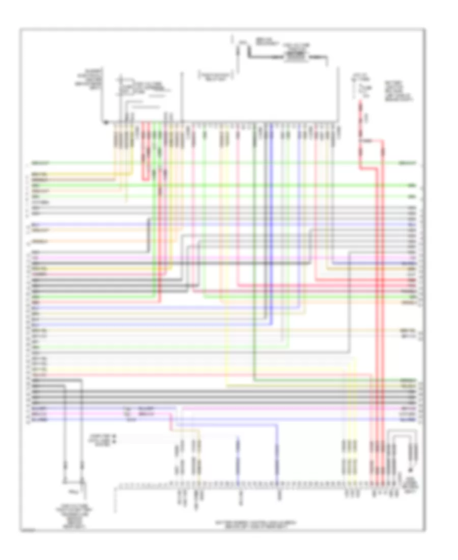
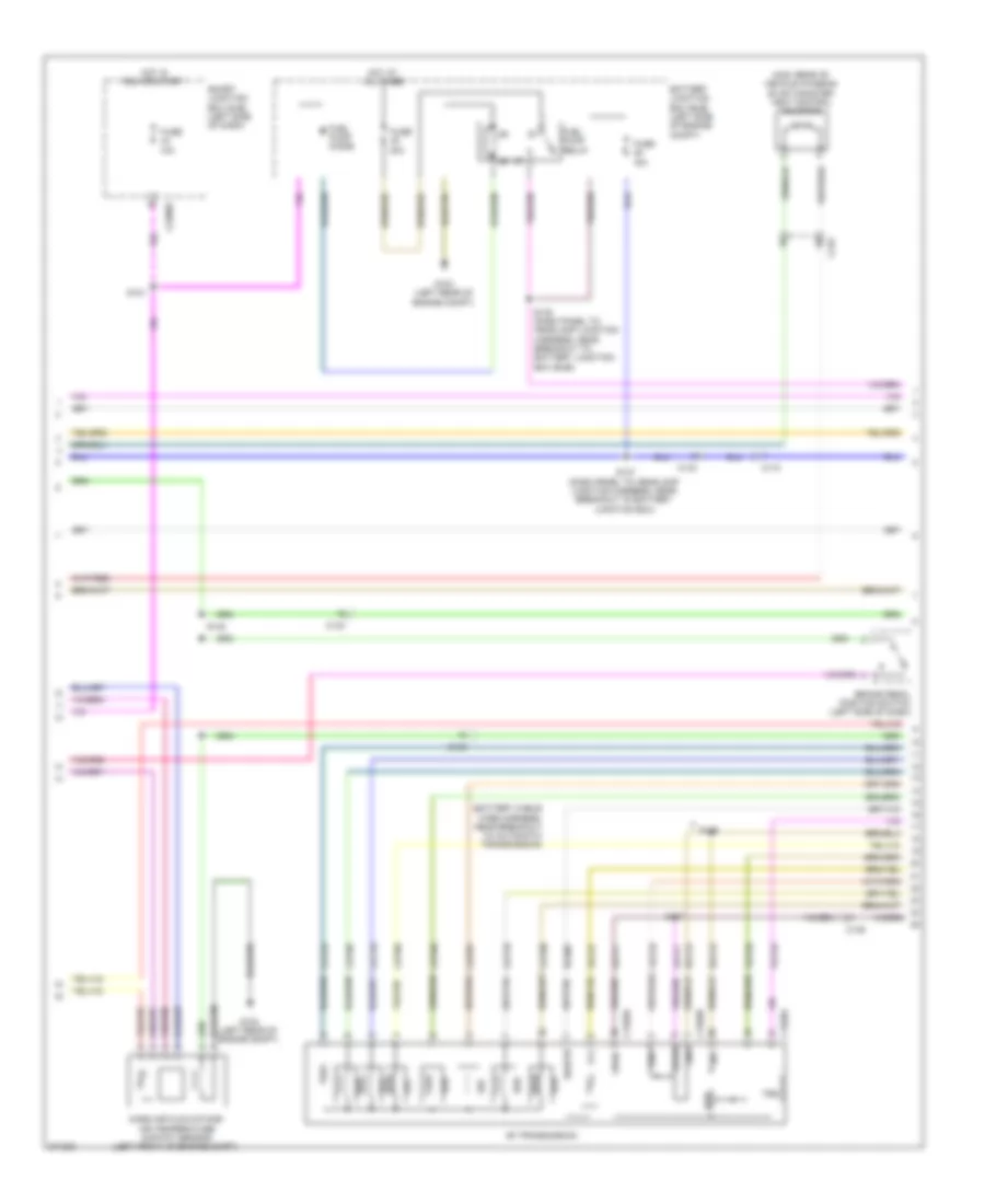
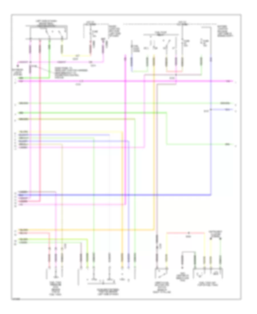
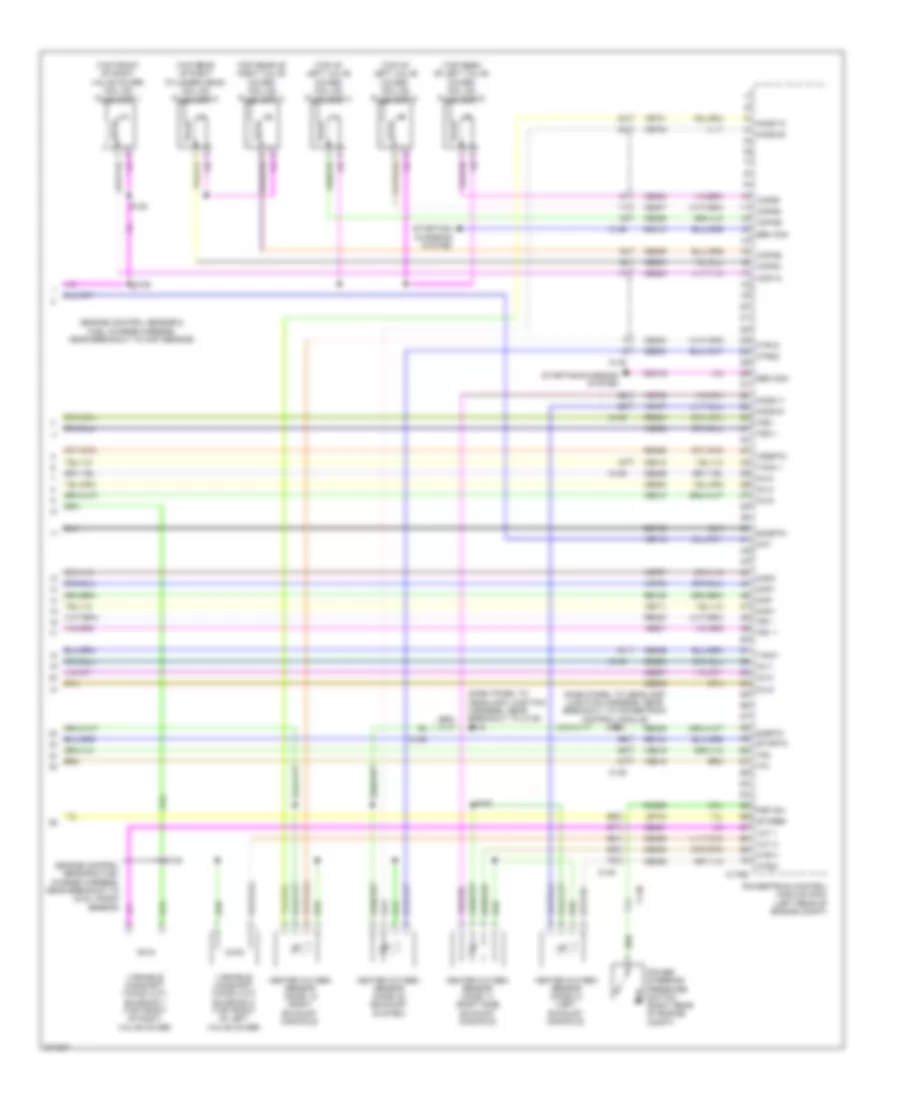
2.5L, Engine Performance Wiring Diagram (2 of 5) for Ford Fusion S 2012
List of elements for 2.5L, Engine Performance Wiring Diagram (2 of 5) for Ford Fusion S 2012:
- (battery cable wire harness, near breakout to automatic transmission)
- (mkz: rear of vehicle chassis) evap canister vent control solenoid
- (starter motor relay & battery ground harness, near breakout to battery junction box (bjb)) s140
- 10a
- 15a
- 30a
- 6f transmission
- Battery junction box (bjb) (left side of engine compt)
- Brake pedal position switch (left side of dash)
- C133
- C139
- C1520a
- C1520b
- C219
- C2280e
- Cet05
- Cet06
- Cet07
- Cet08
- Cet09
- Cet10
- Cet18
- Cet25
- Fuel pump diode
- Fuel pump relay
- Fuse
- G102 (left rear of engine compt)
- G103
- Gnd
- Hot at all times
- Hot in run or start
- Le111
- Lpc
- M/t
- Mass air flow/intake air temperature (maf/iat) sensor (left front of engine compt)
- Oss
- Re406
- Ret24
- S121
- S137
- S146
- S147
- Sigrtn
- Smart junction box (sjb) (left side of dash)
- Ssa
- Ssb
- Ssc
- Ssd
- Sse
- Tcc
- Tft
- Trs
- Tspc
- Tss
- Vet26
- Vet27
- Vet32
- Vet33
- Vpwr
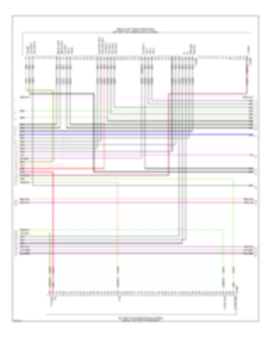
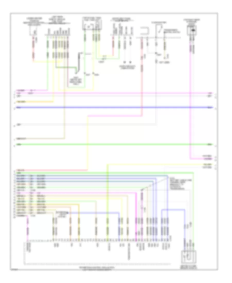
2.5L, Engine Performance Wiring Diagram (3 of 5) for Ford Fusion S 2012
List of elements for 2.5L, Engine Performance Wiring Diagram (3 of 5) for Ford Fusion S 2012:
- (dash panel to headlamp junction harness, near breakout to battery junction box)
- (front of engine) knock sensor
- (left rear of engine) manifold absolute pressure (map) sensor
- (left rear side of vehicle) fuel pump control module
- (top of fuel tank) fuel tank unit
- C139
- C175t
- C3047
- Ce226
- Ce233
- Ce608
- Ce903
- Ce904
- Cet05
- Cet06
- Cet07
- Cet08
- Cet09
- Cet10
- Cet18
- Cet25
- Cet34
- Cls28
- Computer data lines system
- Cpp-bt
- Cpp-tt
- Cr167
- Cruise control system
- Ens
- Exterior lights system
- Fpc
- Fpm
- Fppwr
- Fprtn
- Fuel level return
- Fuel level signal
- G403 (above left rear wheel well)
- Gd151
- Gnd
- Heated oxygen sensor (ho2s) 12 (exhaust manifold)
- Ho2s-12
- Hs can+
- Hs can-
- Htr-12
- Instrument panel cluster (ipc)
- Le111
- Lpc
- Oss
- Powertrain control module (pcm) (left rear of engine compt)
- Re226
- Re406
- Ret24
- Rlc
- Rmc32
- S182
- S406
- S407
- Sig rtn
- Ssa
- Ssb
- Ssc
- Ssd
- Sse
- Tcc
- Tcs
- Tft
- Trs
- Trs/oss/tss vpwr
- Tspc
- Tss
- Tss/oss/tr gnd
- Ve225
- Ve518
- Ve731
- Ve806
- Vet26
- Vet27
- Vet32
- Vet33
- Vmc11
- Vpwr
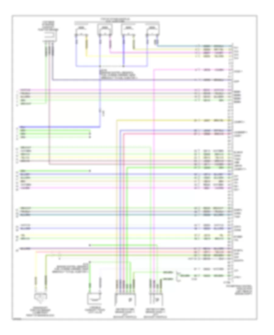
2.5L, Engine Performance Wiring Diagram (4 of 5) for Ford Fusion S 2012
List of elements for 2.5L, Engine Performance Wiring Diagram (4 of 5) for Ford Fusion S 2012:
- (engine control sensor & fuel charge harness, near breakout to fuel injector 2) s135
- (rear of intake manifold) evaporative emission (evap) canister purge valve
- (top center of cylinder head) cylinder head temperature sensor
- (top rear of engine) egr stepper motor
- C139
- Coil
- Coil on plug (cop) 1 (top front of valve cover)
- Coil on plug (cop) 2 (top center of valve cover)
- Coil on plug (cop) 3 (top center of valve cover)
- Coil on plug (cop) 4 (top rear of valve cover)
- Electronic throttle control (etc) module (on throttle body)
- Ignition transformer capacitor (top rear of valve cover)
- Output shaft speed (oss) sensor (m/t) (top of transmission)
- S181 (engine control sensor & fuel charge wire harness, near breakout to c133)
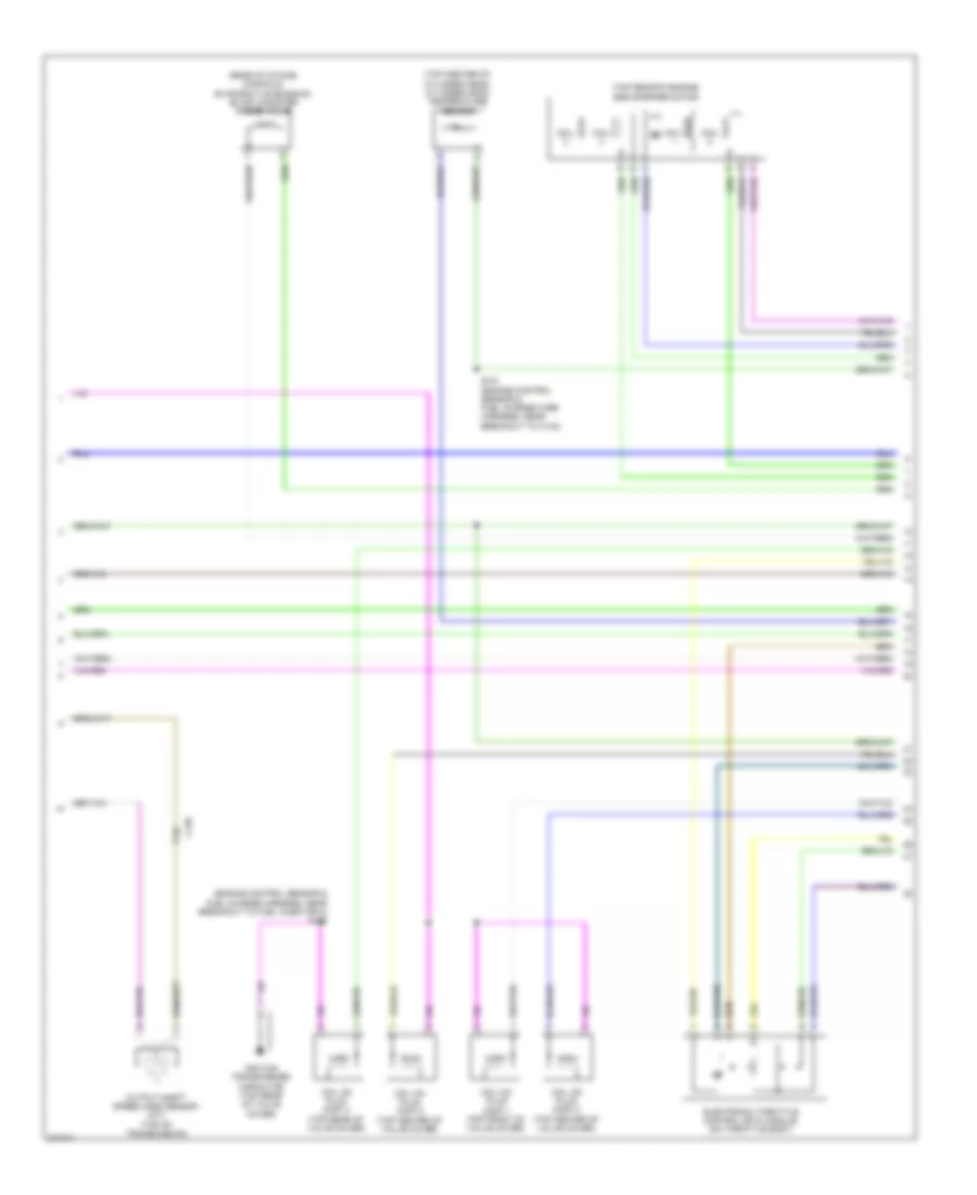
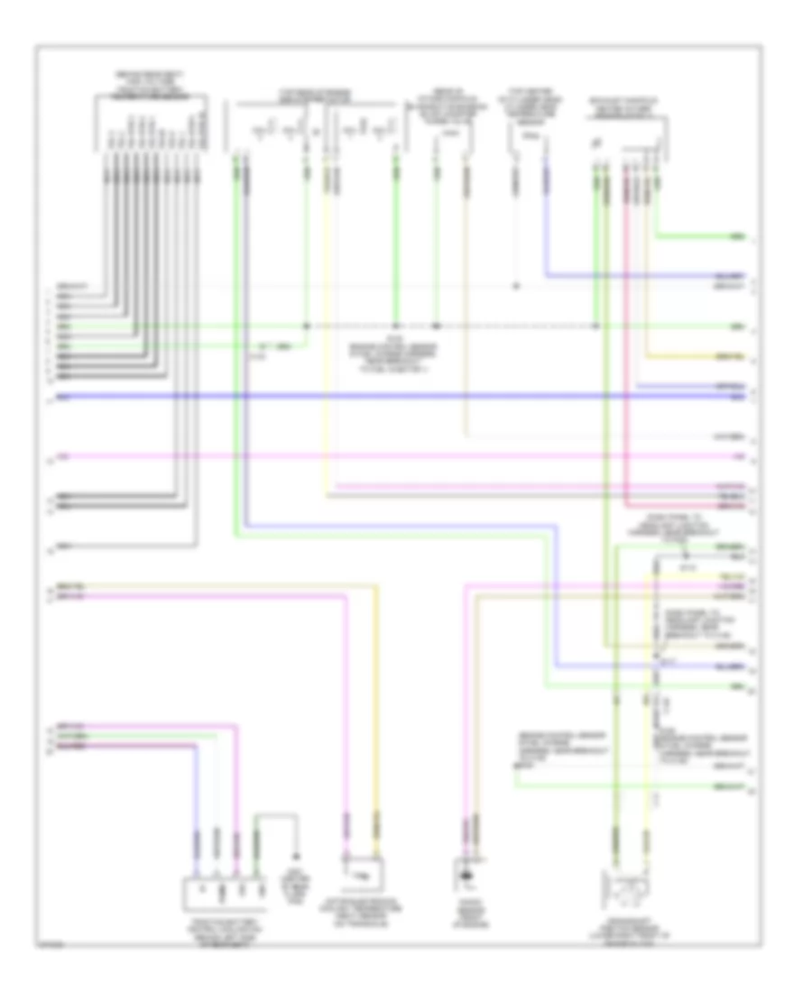
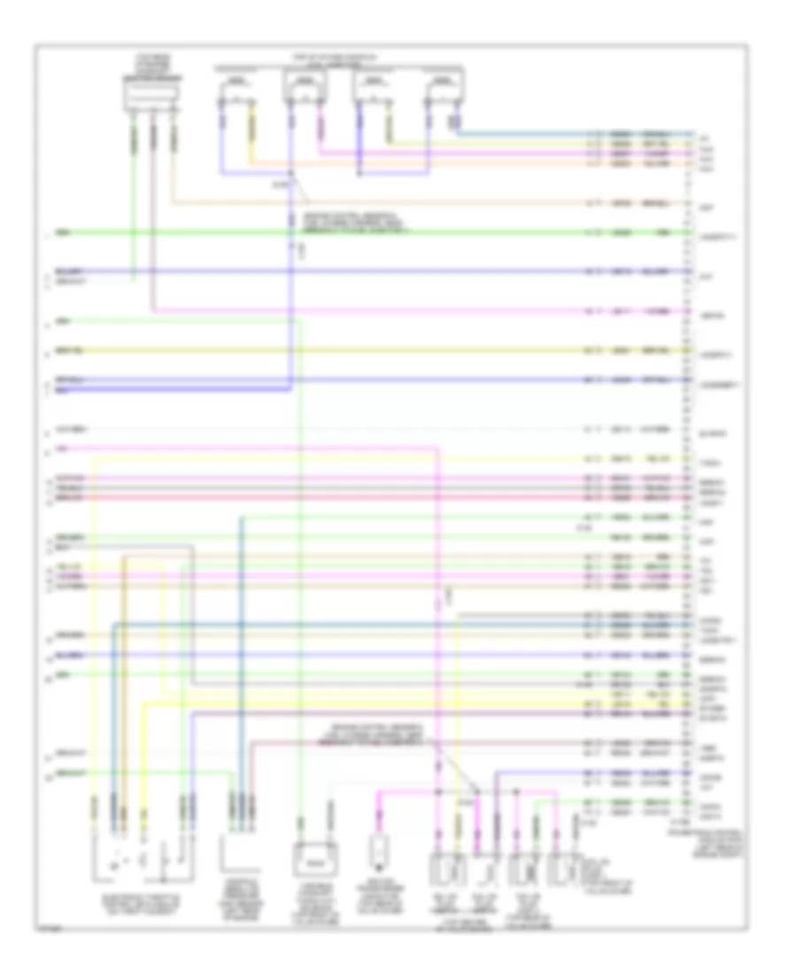
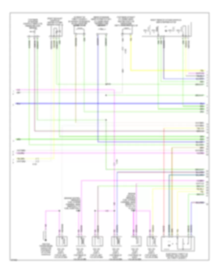
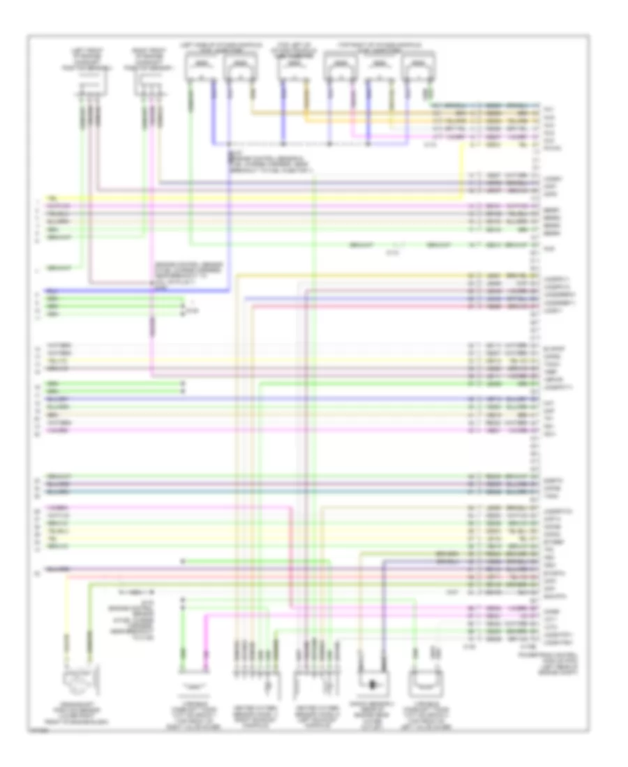
2.5L, Engine Performance Wiring Diagram (5 of 5) for Ford Fusion S 2012
List of elements for 2.5L, Engine Performance Wiring Diagram (5 of 5) for Ford Fusion S 2012:
- (engine control sensor & fuel charge harness, near breakout to fuel injector 1)
- (top of intake manifold) fuel injectors
- (top rear of engine) camshaft position sensor
- A/t
- C133
- C145
- C175e
- Ce101
- Ce102
- Ce103
- Ce104
- Ce113
- Ce205
- Ce206
- Ce207
- Ce208
- Ce235
- Ce303
- Ce304
- Ce305
- Ce306
- Ce412
- Ce422
- Ce426
- Cht
- Ckp+
- Ckp-
- Cmp1
- Cop1a
- Cop2d
- Cop3b
- Cop4c
- Crankshaft position sensor (lower right front of engine block)
- De135
- Eegr1
- Eegr2
- Eegr3
- Eegr4
- Etcref
- Etcrtn
- Evapcp
- Heated oxygen sensor (ho2s) 11 (a/t) (exhaust manifold)
- Heated oxygen sensor (ho2s) 11 (m/t) (exhaust manifold)
- Ho2s-11
- Htr-11
- Inj1
- Inj2
- Inj3
- Inj4
- Ks1+
- Ks1-
- Le111
- Le134
- Le423
- Le448
- Le451
- Le452
- M/t
- Map
- Powertrain control module (pcm) (left rear of engine compt)
- Re134
- Re135
- Re323
- Re405
- S138 (engine control sensor & fuel charge harness, near breakout to fuel injector 1)
- Shd rtn
- Sigrtn
- Tacm+
- Tacm-
- Tp1
- Tp2
- Uo2s11
- Uo2sgref11
- Uo2spc11
- Uo2spct11
- Variable camshaft timing (vct) valve
- Vbpwr
- Vct
- Ve706
- Ve711
- Ve712
- Ve735
- Ve801
- Ve803
- Ve818
- Ve819
- Ve826
- Vref
2.5L HYBRID
2.5L Hybrid, Engine Performance Wiring Diagram (1 of 8) for Ford Fusion S 2012
List of elements for 2.5L Hybrid, Engine Performance Wiring Diagram (1 of 8) for Ford Fusion S 2012:
- (dash panel to headlamp junction harness, near breakout to battery junction box) s157
- (under rear seat) evap canister vent control solenoid
- (under rear seat) fuel vapor vent valve
- A/c pressure transducer (right rear of engine compt)
- Accelerator pedal position (app) sensor (on accelerator pedal bracket)
- Acpt
- App
- App2
- Apprtn
- Apprtn2
- Appvref
- Appvref2
- Bpp
- Bps
- C175b
- C214
- C219
- C2280b
- C2280d
- C2280e
- Canv
- Case gnd
- Cbb40
- Cbk01
- Cbp28
- Cbp44
- Ccb08
- Cdb08
- Ce114
- Ce302
- Ce420
- Ces09
- Computer data lines system
- Cooling fans system
- Cruise control system
- Cto
- Exterior lights system
- Fcv
- Feps
- Fpc
- Fpm
- Ftp
- Ftpref
- Fuel tank pressure (ftp) sensor (top of fuel tank)
- Fuse 10a
- Fuse 15a
- Fuse 5a
- Fvvv
- G102 (left rear of engine compt)
- Gd120
- Hot at all times
- Hot in start or run
- Hs can+
- Hs can-
- Iat
- Ignition switch
- Injpwrm
- Isp-r
- Isp-r/s
- Kapwr
- Le136
- Le137
- Le230
- Le424
- Lock
- Maf
- Mafrtn
- Off
- Pcmrc
- Powertrain control module (pcm) (left rear of engine compt)
- Pwr gnd
- Re136
- Re137
- Re325
- Re407
- Res08
- Run/ run/ acc
- S121
- S195 (dash panel to headlamp junction harness, near breakout to bjb)
- S230
- Sbb23
- Sccs
- Sccsrtn
- Sigrtn
- Smart junction box (sjb) (left side of dash)
- Start
- Tgac
- Tmac
- Vdb04
- Vdb05
- Ve225
- Ve518
- Ve701
- Ve702
- Ve740
- Ve808
- Ve922
- Vec03
- Ves10
- Vh433
- Vmc02
- Vmc05
- Vpwr
- Vref
- Vsout
- Vyt05
- Vyt06
- Wiper/washer system
2.5L Hybrid, Engine Performance Wiring Diagram (2 of 8) for Ford Fusion S 2012
List of elements for 2.5L Hybrid, Engine Performance Wiring Diagram (2 of 8) for Ford Fusion S 2012:
- (body main harness, near breakout to g401)
- (not used) c133
- 10a
- 15a
- 20a
- 30a
- 40a
- Battery junction box (bjb) (left side of engine compt)
- Brake pedal position switch (left side of dash)
- C219
- C3047
- C310a
- Cbb48
- Ce226
- Computer data lines system
- Cr167
- Ens
- Fpc
- Fpm
- Fppwr
- Fprtn
- Fuel level return
- Fuel level signal
- Fuel pump control module (left rear side of vehicle)
- Fuel pump diode
- Fuel tank unit (top of fuel tank)
- Fuse
- G102 (left rear of engine compt)
- G104 (right front of engine compt)
- G403 (above left rear wheel well)
- Gd151
- Gnd
- Heater pump relay
- Hot at all times
- Ifs vpwr
- Injector relay
- Instrument panel cluster (ipc)
- M/e coolant pump relay
- Mass air flow/intake air temperature (maf/iat) sensor (on air cleaner inlet duct)
- Ms can+
- Ms can-
- Nca
- Re226
- Restraints control module (rcm) (under center console)
- Reverse lamp relay
- S119
- S137
- S140
- S144
- S461
- S462
- S463
- S464 (body main harness, near breakout to left rear wheel speed sensor)
- Ve225
- Ve518
2.5L Hybrid, Engine Performance Wiring Diagram (3 of 8) for Ford Fusion S 2012
List of elements for 2.5L Hybrid, Engine Performance Wiring Diagram (3 of 8) for Ford Fusion S 2012:
- (dash panel to headlamp junction harness, near breakout to auxiliary relay box)
- (dash panel to headlamp junction harness, near breakout to battery junction box)
- (dash panel to headlamp junction harness, near breakout to bjb)
- Air conditioning system
- Auxiliary relay box (left front of engine compt)
- C133
- C1458a
- C1458b
- C1458c
- C175t
- Cbb39
- Ce233
- Ce318
- Ch307
- Cls28
- Computer data lines system
- Cto
- Cyb03
- Cyb04
- Cyb16
- Cyb17
- Cyt08
- Dual battery fuse assembly (front of battery)
- Exterior lights system
- G103 (left front of engine compt)
- Gd121
- Gmsdn
- Gnd
- Ho2s12
- Hot at all times
- Hpcr
- Hs can +
- Hs can -
- Htr12
- Hv+
- Hv-
- Hvi+
- Hyi-
- Hyt03
- Hyt04
- Isdn1
- Isdn2
- Let56
- Let57
- Mect
- Mfcspr
- Midi fuse (pink) 200a c1620b
- Pcm power relay
- Powertrain control module (pcm) (left rear of engine compt)
- Re406
- Red
- Ret56
- Ret57
- Rlc
- S143
- S193
- S194
- Sbb23
- Sigrtn
- Tgac
- Tmac
- Tr-a1
- Tr-a1 ref
- Tr-a1 rtn
- Tr-a2
- Tr-a2 ref
- Tr-a2 rtn
- Transaxle control module (on transaxle)
- Transmission range (tr) sensor (on transaxle)
- Vbatt
- Vdb04
- Vdb05
- Ve731
- Ve810
- Vet56
- Vet57
- Vmc02
- Vpwr
- Vyt05
- Vyt06
2.5L Hybrid, Engine Performance Wiring Diagram (4 of 8) for Ford Fusion S 2012
List of elements for 2.5L Hybrid, Engine Performance Wiring Diagram (4 of 8) for Ford Fusion S 2012:
- (exhaust manifold) heated oxygen sensor (ho2s) 12
- (left front of engine) air conditioning compressor module (accm)
- (on transaxle assembly)
- (right rear of engine compt) anti-lock brake system (abs) control module
- (right rear of engine compt) high voltage junction box
- Battery energy control module (becm) (behind left side of rear seat)
- Becm in+
- Becm in-
- C133
- C1457a
- C1457b
- C1457c
- C1457d
- C1469a
- C1469b
- C4237b
- Cbk03
- Ch401
- Computer data lines system
- Cont crl posh
- Cont crl posl
- Cyb03
- Cyd01
- Cyd02
- Dc/dc converter module
- Fvi+
- Fvi-
- G105
- Gd108
- Gnd
- Hs can+
- Hs can-
- Hv+
- Hv-
- Hvdc+
- Hvdc-
- Hvi+
- Hvi-
- Hyt03
- Hyt04
- Instr can h
- Instr can l
- J1-a39
- J1-a41
- J1-a44
- J1-a47
- J1-a55
- J1-a56
- J1-a58
- J1-a59
- J1-a61
- J1-a62
- J1a02
- J1a07
- J1a11
- J1a16
- J1a17
- J1a18
- J1a51
- J1a65
- J1a66
- J1a69
- J1a70
- Nca
- Pack hs can h
- Pack hs canl
- Prech ctlh
- Prech ctll
- Pwr gnd
- Red
- Sdc02
- Sig rtn
- Temp inlet
- Temp inlet rtn
- Vbatt
- Vdb04
- Vdb05
- Vpwr
2.5L Hybrid, Engine Performance Wiring Diagram (5 of 8) for Ford Fusion S 2012
List of elements for 2.5L Hybrid, Engine Performance Wiring Diagram (5 of 8) for Ford Fusion S 2012:
- 100a
- Battery energy control module (becm) (behind left side of rear seat)
- Battery junction box (bjb) (left side of engine compt)
- Bussed electrical center (behind rear seat)
- C219
- C4001
- C4002
- C4236a
- C4236b
- C4236c
- C4236d
- C4236e
- C4237a
- Cbb48
- Computer data lines system
- Cr167
- Crs
- Cyb16
- Cyb17
- Ens
- Fan1 fbb
- Fan1 pwmb
- Fuse 10a
- Fuse 40a
- G300 (under driver's seat)
- Gd126
- Gnd
- High voltage low amperage fuse
- High voltage traction battery
- High voltage traction battery temperature sensor (behind rear seat)
- Hot at all times
- Hs can+
- Hs can-
- Hvi+
- Hvi-
- Isdn1
- Isdn2
- Nca
- Pnk
- Positive pack relay 60a
- Psr
- Red
- S460
- Sbb17
- Service disconnect
- Vdb04
- Vdb05
- Vyb18
- Vyb19
2.5L Hybrid, Engine Performance Wiring Diagram (6 of 8) for Ford Fusion S 2012
List of elements for 2.5L Hybrid, Engine Performance Wiring Diagram (6 of 8) for Ford Fusion S 2012:
- (behind left side of rear seat) battery pack sensor module (bpsm)
- Battery pack sensor module (bpsm) (behind left side of rear seat)
- C4238a
- C4238b
- Cs aout 1
- Cs aout 2
- Cs gnd
- Cs vref
- Instr can h
- Instr can l
- J1a02
- J1a07
- J1a11
- J1a16
- J1a17
- J1a18
- J1a51
- J1a65
- J1a66
- J1a69
- J1a70
- J2a15
- J2a16
- J2a17
- J2a36
- J2a67
- J2a70
- J2b1
- J2b12
- J2b13
- J2b14
- J2b2
- J2b24
- J2b25
- J2b26
- J2b27
- J2b3
- J2b35
- J2b36
- J2b37
- J2b38
- Ldl
- Nca
- Pack hs can h
- Pack hs can l
- Pnk
- Pwr gnd
- Red
- Sig rtn
- Tsl 1
- Tsl 2
- Tsl 3
- Tsl 9
- Tsl rtn 1
- Tsl rtn 10
- Tsl rtn 2
- Tsl rtn 3
- Tsl rtn 9
- Tsl10
- V cont pos
- V sd
2.5L Hybrid, Engine Performance Wiring Diagram (7 of 8) for Ford Fusion S 2012
List of elements for 2.5L Hybrid, Engine Performance Wiring Diagram (7 of 8) for Ford Fusion S 2012:
- (behind rear seat) high voltage traction battery temperature sensor
- (dash panel to headlamp junction harness, near breakout to c145)
- (dash panel to headlamp junction harness, near breakout to pcm)
- (engine control sensor & fuel charge harness, near breakout to c145) s180
- (exhaust manifold) heated oxygen sensor (ho2s) 11
- (rear of intake manifold) evaporative emission (evap) canister purge valve
- (top center of cylinder head) cylinder head temperature sensor
- (top rear of engine) egr stepper motor
- C133
- C145
- Coil
- Crankshaft position sensor (lower right front of engine block)
- Fbb
- G401 (center of rear floor pan)
- Gnd
- Knock sensor (front of engine)
- Motor electronics coolant temperature (mect) sensor (on transaxle)
- Nca
- Pwmb
- S117
- S118
- S138 (engine control sensor & fuel charge harness, near breakout to fuel injector 1)
- S185 (engine control sensor & fuel charge harness, near breakout to c145)
- Traction battery control cooling fan (behind left side of rear seat)
- Tsl 1
- Tsl 2
- Tsl 3
- Tsl 9
- Tsl rtn 1
- Tsl rtn 10
- Tsl rtn 2
- Tsl rtn 3
- Tsl rtn 9
- Tsl10
2.5L Hybrid, Engine Performance Wiring Diagram (8 of 8) for Ford Fusion S 2012
List of elements for 2.5L Hybrid, Engine Performance Wiring Diagram (8 of 8) for Ford Fusion S 2012:
- (engine control sensor & fuel charge harness, near breakout to fuel injector 1)
- (engine control sensor & fuel charge harness, near breakout to fuel injector 4)
- (top center of valve cover)
- (top of intake manifold) fuel injectors
- (top rear of engine) camshaft position sensor
- C133
- C145
- C175e
- Ce101
- Ce102
- Ce103
- Ce104
- Ce113
- Ce205
- Ce206
- Ce207
- Ce208
- Ce235
- Ce303
- Ce304
- Ce305
- Ce306
- Ce412
- Ce422
- Ce426
- Cht
- Ckp+
- Ckp-
- Cmp
- Coil on plug (cop) 1 (top front of valve cover)
- Coil on plug (cop) 2
- Coil on plug (cop) 3
- Coil on plug (cop) 4 (top rear of valve cover)
- Cop1a
- Cop2d
- Cop3b
- Cop4c
- De135
- Egrmc1
- Egrmc2
- Egrmc3
- Egrmc4
- Electronic throttle control (etc) module (on throttle body)
- Etcref
- Etcrtn
- Evapcp
- Ignition transformer capacitor (top rear of valve cover)
- In1
- Inj2
- Inj3
- Inj4
- Ks1+
- Ks1-
- Le111
- Le134
- Le423
- Le448
- Le451
- Le452
- Manifold absolute pressure (map) sensor (left rear of engine)
- Map
- Powertrain control module (pcm) (left rear of engine compt)
- Re134
- Re135
- Re323
- Re405
- S135
- S139
- Shdrtn
- Sigrtn
- Tacm+
- Tacm-
- Tp1
- Tp2
- Uo2s11
- Uo2sgref11
- Uo2shtr11
- Uo2spc11
- Uo2spct11
- Variable camshaft timing (vct) solenoid (top front of valve cover)
- Vbpwr
- Vct
- Ve706
- Ve711
- Ve712
- Ve801
- Ve803
- Ve818
- Ve819
- Ve826
- Vref
3.0L FLEX FUEL
3.0L Flex Fuel, Engine Performance Wiring Diagram (1 of 5) for Ford Fusion S 2012
List of elements for 3.0L Flex Fuel, Engine Performance Wiring Diagram (1 of 5) for Ford Fusion S 2012:
- (dash panel to headlamp junction harness, near breakout to battery junction box) s144
- 10a
- 15a
- 20a
- 40a
- A/c clutch relay
- A/c pressure transducer sensor (center rear of engine compt)
- Accelerator pedal position sensor (left side of dash)
- Accr
- Acpt
- Air conditioning system
- App 1
- App2
- Apprtn
- Apprtn2
- Appvref
- Appvref2
- Battery junction box (bjb) (left side of engine compt)
- Bpp
- Bps
- C175b
- C214
- C219
- Canv
- Case gnd
- Cbb46
- Cbk01
- Cbp44
- Ccb08
- Cdb08
- Cdc10
- Cdc12
- Cdc15
- Cdc35
- Ce114
- Ce302
- Ce336
- Ces09
- Cet42
- Cet43
- Ch302
- Computer data lines system
- Cooling fans system
- Cruise control system
- Exterior lights system
- Fcv
- Feps
- Fpc
- Fpm
- Ftp
- Ftptref
- Fuel tank pressure (ftp) sensor (top of fuel tank)
- Fuse
- G102 (left rear of engine compt)
- Gd120
- Gencom
- Genmon
- Hot at all times
- Hs can+
- Hs can-
- Iat
- Ign
- Kapwr
- Le136
- Le137
- Le230
- Le424
- Maf
- Mafrtn
- Pcm power relay
- Pcmrc
- Powertrain control module (pcm) (left rear of engine compt)
- Pwr gnd
- Re136
- Re137
- Re325
- Re407
- Res08
- Reverse lamp relay
- S119
- S125 (dash panel to headlamp junction harness, near breakout to g102)
- S143
- S157
- Sbb23
- Sccs
- Sccsrtn
- Shift interlock system
- Sigrtn
- Smc
- Smr
- Smrc
- Starting/charging system
- Tip +
- Tip -
- Vdb04
- Vdb05
- Ve225
- Ve518
- Ve701
- Ve702
- Ve740
- Ve808
- Ve922
- Vec03
- Ves10
- Vh433
- Vmc05
- Vpwr
- Vref
- Vsout
- Wiper/washer system
3.0L Flex Fuel, Engine Performance Wiring Diagram (2 of 5) for Ford Fusion S 2012
List of elements for 3.0L Flex Fuel, Engine Performance Wiring Diagram (2 of 5) for Ford Fusion S 2012:
- (battery cable wire harness, near breakout to automatic transmission)
- (mkz: rear of vehicle chassis) evap canister vent control solenoid
- 10a
- 15a
- 30a
- 6f transmission
- Battery junction box (bjb) (left side of engine compt)
- Brake pedal position switch (left side of dash)
- C110
- C133
- C139
- C1520a
- C1520b
- C219
- C2280e
- Cet05
- Cet06
- Cet07
- Cet08
- Cet09
- Cet10
- Cet18
- Cet25
- Fuel pump diode
- Fuel pump relay
- Fuse
- G102 (left rear of engine compt)
- G103 (left rear of engine compt)
- Gnd
- Hot at all times
- Hot in run or start
- Le111
- Lpc
- Mass air flow/intake air temperature (maf/iat) sensor (left front of engine compt)
- Oss
- Re406
- Ret24
- S121
- S130 (dash panel to headlamp junction harness, near breakout to battery junction box (bjb))
- S137 (dash panel to headlamp junction harness, near breakout to battery junction box)
- S140
- S146
- S147
- Sigrtn
- Smart junction box (sjb) (left side of dash)
- Ssa
- Ssb
- Ssc
- Ssd
- Sse
- Tcc
- Tft
- Trs
- Tspc
- Tss
- Vet26
- Vet27
- Vet32
- Vet33
- Vpwr
3.0L Flex Fuel, Engine Performance Wiring Diagram (3 of 5) for Ford Fusion S 2012
List of elements for 3.0L Flex Fuel, Engine Performance Wiring Diagram (3 of 5) for Ford Fusion S 2012:
- (left rear side of vehicle) fuel pump control module
- (not used)
- (top of fuel tank) fuel tank unit
- (top right rear of engine) knock sensor 1
- (under center console) restraints control module (rcm)
- C139
- C175t
- C215
- C219
- C3047
- C310a
- Ce226
- Ce233
- Ce234
- Ce608
- Cet05
- Cet06
- Cet07
- Cet08
- Cet09
- Cet10
- Cet18
- Cet25
- Cls28
- Computer data lines system
- Cr167
- Ens
- Exterior lights system
- Floor shifter
- Fpc
- Fpm
- Fppwr
- Fprtn
- Fuel level return
- Fuel level signal
- G403 (above left rear wheel well)
- Gd151
- Gnd
- Heated oxygen sensor (ho2s) 22
- Ho2s-12
- Ho2s-22
- Hs can+
- Hs can-
- Htr-12
- Htr-22
- Instrument panel cluster (ipc)
- Le111
- Lpc
- Nca
- Oss
- Powertrain control module (pcm) (left rear of engine compt)
- Re226
- Re406
- Ret24
- Rlc
- S148 (battery cable wire harness, near breakout to automatic transmission)
- S251
- S406
- S407
- Sigrtn
- Ssa
- Ssb
- Ssc
- Ssd
- Sse
- Tcc
- Tft
- Transmission control switch
- Trs
- Trs vpwr
- Tspc
- Tss
- Tss/oss/
- Tss/oss/trs gnd
- Ve225
- Ve518
- Ve731
- Ve733
- Vet26
- Vet27
- Vet32
- Vet33
- Vpwr
3.0L Flex Fuel, Engine Performance Wiring Diagram (4 of 5) for Ford Fusion S 2012
List of elements for 3.0L Flex Fuel, Engine Performance Wiring Diagram (4 of 5) for Ford Fusion S 2012:
- (engine control sensor & fuel charge harness, near breakout to coil on plug 3) s135
- (engine control sensor & fuel charge harness, near breakout to fuel injector 4) s136
- (in front of throttle body) evaporative emission (evap) canister purge valve
- (rear of engine, near water outlet) cylinder head temperature sensor
- (right exhaust manifold) heated oxygen sensor (ho2s) 12
- (right rear of intake manifold) egr stepper motor
- (top rear of engine) manifold absolute pressure (map) sensor
- (top rear of right cylinder head) heated positive crankcase ventilation (pcv) valve
- C133
- Coil
- Coil on plug (cop) 1 (top front of right valve cover)
- Coil on plug (cop) 2 (top of right valve cover)
- Coil on plug (cop) 3 (top rear of right valve cover)
- Coil on plug (cop) 4 (top of left valve cover)
- Coil on plug (cop) 5 (top of left valve cover)
- Coil on plug (cop) 6 (top rear of left valve cover)
- Electronic throttle control (etc) module (on throttle body)
- Ignition transformer capacitor (top front of intake manifold)
- S181
3.0L Flex Fuel, Engine Performance Wiring Diagram (5 of 5) for Ford Fusion S 2012
List of elements for 3.0L Flex Fuel, Engine Performance Wiring Diagram (5 of 5) for Ford Fusion S 2012:
- (engine control sensor & fuel charge harness, near breakout to coil on plug 1) s153
- (left front of engine) camshaft position sensor 2
- (left side of intake manifold) fuel injectors
- (right front of engine) camshaft position sensor 1
- (top left of intake manifold) fuel injector
- (top right of intake manifold) fuel injectors
- C110
- C145
- C175e
- Ce101
- Ce102
- Ce103
- Ce104
- Ce113
- Ce205
- Ce206
- Ce207
- Ce208
- Ce209
- Ce210
- Ce235
- Ce236
- Ce303
- Ce304
- Ce305
- Ce306
- Ce307
- Ce308
- Ce321
- Ce412
- Ce421
- Ce422
- Ce426
- Cht
- Ckp+
- Ckp-
- Cmp1
- Cmp2
- Cop1a
- Cop2c
- Cop3e
- Cop4b
- Cop5d
- Cop6f
- Crankshaft position sensor (lower right front of engine block)
- De135
- Eegr1
- Eegr2
- Eegr3
- Eegr4
- Etcref
- Etcrtn
- Evapcp
- Heated oxygen sensor (ho2s) 11 (right exhaust manifold)
- Heated oxygen sensor (ho2s) 21 (left exhaust manifold)
- Inj1
- Inj2
- Inj3
- Inj4
- Inj5
- Inj6
- Knock sensor 2 (rear of engine near water outlet)
- Ks1+
- Ks1-
- Ks2+
- Ks2-
- Le111
- Le134
- Le423
- Le448
- Le449
- Le450
- Le451
- Le452
- Le453
- Map
- Nca
- Pcvhc
- Powertrain control module (pcm) (left rear of engine compt)
- Re134
- Re135
- Re323
- Re324
- Re405
- S138
- S178 (engine control sensor & fuel charge harness, near breakout to c145)
- Shd rtn
- Sigrtn
- Tacm+
- Tacm-
- Tp1
- Tp2
- Uo2s11
- Uo2s21
- Uo2sgref11
- Uo2sgref21
- Uo2shtr11
- Uo2shtr21
- Uo2spc11
- Uo2spc12
- Uo2spct11
- Uo2spct21
- Variable camshaft timing (vct) solenoid 1 (top front of right valve cover)
- Variable camshaft timing (vct) solenoid 2 (top front of left valve cover)
- Vbpwr
- Vct1
- Vct2
- Ve706
- Ve707
- Ve711
- Ve712
- Ve801
- Ve802
- Ve803
- Ve818
- Ve819
- Ve826
- Ve827
- Vref
3.5L
3.5L, Engine Performance Wiring Diagram (1 of 4) for Ford Fusion S 2012
List of elements for 3.5L, Engine Performance Wiring Diagram (1 of 4) for Ford Fusion S 2012:
- (not used)
- A/c clutch relay
- A/c pressure transducer sensor (center rear of engine compt)
- Accr
- Acpt
- Air conditioning system
- App 2
- App 3
- App1
- Apprtn
- Apprtn2
- Appvref
- Appvref2
- Battery junction box (bjb) (left side of engine compt)
- Bpp
- Bps
- C-sigrtn
- C133
- C175b
- C214
- C219
- C2280e
- Canv
- Case gnd
- Cbb46
- Cbk01
- Cbp44
- Ccb08
- Cdb08
- Cdc12
- Cdc35
- Ce114
- Ce132
- Ce302
- Ce336
- Ce608
- Ces09
- Cet40
- Ch302
- Computer data lines system
- Cooling fans system
- Cruise control system
- Evap canister vent control solenoid (mkz: rear of vehicle chassis)
- Evapcp
- Evaporative emission (evap) canister purge valve (right rear of engine compt)
- Fcv
- Feps
- Floor shifter
- Fpc
- Fpm
- Ftp
- Ftpref
- Fuse 10a
- Fuse 15a
- Fuse 40a
- G102 (left rear of engine compt)
- Gd120
- Hot at all times
- Hot in start or run
- Hs can +
- Hs can -
- Iat
- Ignition
- Kapwr
- Le136
- Le137
- Le230
- Le424
- Maf
- Mafrtn
- Mass air flow/intake air temperature (maf/iat) sensor (left side of engine compt)
- O/d
- Pcm power relay
- Pcmrc
- Powertrain control module (pcm) (left rear of engine compt)
- Pwr
- Pwr gnd
- Re136
- Re137
- Re325
- Re407
- Res08
- Reverse lamp relay
- S119
- S121
- S125
- S140
- S143
- S144
- S179
- S251
- Sbb23
- Sccs
- Sccsrtn
- Sigrtn
- Smart junction box (sjb) (left side of dash)
- Smc
- Smr
- Smrc
- Starting/charging system
- Trsw pn
- Vdb04
- Vdb05
- Ve225
- Ve701
- Ve702
- Ve703
- Ve740
- Ve808
- Ve922
- Vec03
- Ves10
- Vh433
- Vpwr
- Vref
3.5L, Engine Performance Wiring Diagram (2 of 4) for Ford Fusion S 2012
List of elements for 3.5L, Engine Performance Wiring Diagram (2 of 4) for Ford Fusion S 2012:
- (dash panel to headlamp junction harness, near breakout to powertrain control module)
- (left side of dash) brake pedal position switch
- Accelerator pedal position sensor (left side of dash)
- Battery junction box (bjb) (left side of engine compt)
- Bpp c2280b
- C133
- C214
- C219
- C2280d
- Exterior lights system
- Fuel pump diode
- Fuel pump relay
- Fuel tank pressure (ftp) sensor (top of fuel tank)
- Fuel tank unit (top of fuel tank)
- Fuse 15a
- Fuse 30a
- G401 (center of rear floor pan)
- Hot at all times
- Inertia fuel shutoff (ifs) switch (base of right "a" pillar)
- Instrument cluster system
- S130
- S137
- S142
- S402
- Smart junction box (sjb) (left side of dash)
3.5L, Engine Performance Wiring Diagram (3 of 4) for Ford Fusion S 2012
List of elements for 3.5L, Engine Performance Wiring Diagram (3 of 4) for Ford Fusion S 2012:
- (dash panel to headlamp junction harness, near breakout to c145) s117
- (dash panel to headlamp junction harness, near breakout to pcm connector) s176
- (rear of left cylinder head) camshaft position sensor 2
- (right front of engine) camshaft position sensor 1
- 6 speed aw21 transmission control module (tcm)
- C133
- C144
- C145
- C192
- Crankshaft position sensor (lower left rear of engine block)
- Cylinder head temperature (cht) sensor (front of right cylinder head)
- Electronic throttle control (etc) module (on throttle body)
- Fuel injectors (fuel injectors 1, 2 & 3: top right of intake manifold) (fuel injectors 5 & 6: left side of intake manifold) ((fuel injector 4: top left of intake manifold)
- Knock sensor
- Lock start
- S126
- S159
- S177
3.5L, Engine Performance Wiring Diagram (4 of 4) for Ford Fusion S 2012
List of elements for 3.5L, Engine Performance Wiring Diagram (4 of 4) for Ford Fusion S 2012:
- (dash panel to headlamp junction harness, near breakout to c145) s116
- (dash panel to headlamp junction harness, near breakout to powertrain control module) s102
- (engine control sensor & fuel charge harness, near breakout to ckp sensor)
- (engine control sensor & fuel charge harness, near breakout to dual knock sensor)
- (top front of right valve cover) coil on plug (cop) 1
- (top of left valve cover) coil on plug (cop) 4
- (top of left valve cover) coil on plug (cop) 5
- (top rear of left valve cover) coil on plug (cop) 6
- (top rear of right cylinder head) coil on plug (cop) 2
- (top rear of right valve cover) coil on plug (cop) 3
- C140
- C145
- C175e
- Ccs09
- Cdc10
- Cdc15
- Ce205
- Ce206
- Ce207
- Ce208
- Ce209
- Ce210
- Ce233
- Ce234
- Ce235
- Ce236
- Ce303
- Ce304
- Ce305
- Ce306
- Ce307
- Ce308
- Ce412
- Ce421
- Ce422
- Ce426
- Cht
- Ckp+
- Ckp-
- Cmp1
- Cmp2
- Cop1a
- Cop2c
- Cop3e
- Cop4b
- Cop5d
- Cop6f
- De135
- Etcref
- Etcrtn
- Gen com
- Gen mon
- Heated oxygen sensor (ho2s) 11 (right side exhaust manifold)
- Heated oxygen sensor (ho2s) 12 (right exhaust manifold)
- Heated oxygen sensor (ho2s) 21 (left exhaust manifold)
- Heated oxygen sensor (ho2s) 22 (exhaust system)
- Ho2s-11
- Ho2s-12
- Ho2s-21
- Ho2s-22
- Htr11
- Htr12
- Htr21
- Htr22
- Inj-1
- Inj-2
- Inj-3
- Inj-4
- Inj-5
- Inj-6
- Ks1 +
- Ks1 -
- Ks2 +
- Ks2 -
- Le134
- Power steering pressure switch (right rear of engine compt)
- Powertrain control module (pcm) (left rear of engine compt)
- Psp sw
- Re134
- Re135
- Re323
- Re324
- Re405
- Re429
- S135
- S136
- S138
- S180
- Shdrtn
- Sigrtn
- Starting/ charging system
- Starting/charging system
- Tacm +
- Tacm -
- Tp1
- Tp2
- Variable camshaft timing (vct) solenoid 1 (top front of right valve cover)
- Variable camshaft timing (vct) solenoid 2 (top front of left valve cover)
- Vct 1
- Vct 2
- Ve706
- Ve707
- Ve711
- Ve712
- Ve731
- Ve733
- Ve735
- Ve737
- Ve801
- Ve802
- Ve818
- Ve819
- Vrsrtn
EXTERIOR LIGHTS
Backup Lamps Wiring Diagram, A/T for Ford Fusion S 2012
List of elements for Backup Lamps Wiring Diagram, A/T for Ford Fusion S 2012:
- (hybrid: center rear of luggage compt) (except hybrid: center rear of trunk compt) g400
- (mkz hybrid: trunk harness wire harness, near breakout to c406) (mkz except hybrid: body main harness, near breakout to left rear turn lamp)
- 3.5l
- 6 speed aw21 transmission control module (tcm)
- 6f transmission (2.5l & 3.0l)
- Auto dimming interior mirror (w/ sync)
- Battery junction box (bjb) (left side of engine compt)
- C139
- C140
- C1520a
- C175t
- C219
- C3053
- Cls28
- Except hybrid
- Fuse 10a
- Hot in start or run
- Hybrid
- Left reversing lamp
- Powertrain control module (pcm) (left rear of engine compt)
- Rear view camera display mirror (w/ camera) (center of deck lid)
- Reverse in
- Reverse lamp relay
- Right reversing lamp
- Rlc
- Rvs
- S144
- S307 (except hybrid: body main harness, near breakout to c237) c3050
- S410
- Trs
- Vet32
Backup Lamps Wiring Diagram, M/T for Ford Fusion S 2012
List of elements for Backup Lamps Wiring Diagram, M/T for Ford Fusion S 2012:
- (hybrid: center rear of luggage compt) (except hybrid: center rear of trunk compt) g400
- Battery junction box (bjb) (left side of engine compt)
- C139
- C219
- C3050
- Fuse 10a
- G103 (3.0l: left rear of engine compt) (3.5l: left side of engine compt) (hybrid: left front of engine compt)
- Hot in start or run
- Left reversing lamp
- Reverse lamp relay
- Reversing lamps switch (except hybrid: top of transmission)
- Right reversing lamp
- S144
- S410 (mkz hybrid: trunk harness wire harness, near breakout to c406) (mkz except hybrid: body main harness, near breakout to left rear turn lamp)
Exterior Lamps Wiring Diagram (1 of 2) for Ford Fusion S 2012
List of elements for Exterior Lamps Wiring Diagram (1 of 2) for Ford Fusion S 2012:
- Auto
- Auto lamp
- Boo input
- C1280
- C1281
- C214
- C219
- C2280b
- C2280d
- C2280e
- C2280f
- C3050
- Computer data lines system
- Fuse 15a
- Fuse 20a
- G103 (3.0l: left rear of engine compt) (3.5l: left side of engine compt) (hybrid: left front of engine compt)
- G104 (except 3.5l: right front of engine compt) (3.5l: right side of engine compt)
- G202 (left side of dash)
- G400 (except hybrid: center rear of trunk compt) (hybrid: center rear of luggage compt)
- Hazard on
- Head park
- Hot at all times
- Left front park/turn lamp
- Left front parking lamp
- Left rear park/ turn/stop lamp
- Lf turn lamp (fet)
- Lh turn
- Logic
- Low
- Low beam
- Lr stop/ turn lamp (fet)
- Main light switch
- Ms can +
- Ms can -
- Off
- Park
- Park lamp relay
- Park on
- Rf turn lamp (fet)
- Rh turn
- Right front park/turn lamp
- Right front side lamp
- Right rear park/ turn/stop lamp
- Rr stop/ turn lamp (fet)
- S155 (3.0l: dash panel to headlamp junction harness, near breakout to battery junction box)
- Smart junction box (sjb) (left side of dash)
- Turn
- Turn stop/
Exterior Lamps Wiring Diagram (2 of 2) for Ford Fusion S 2012
List of elements for Exterior Lamps Wiring Diagram (2 of 2) for Ford Fusion S 2012:
- (trunk harness wire harness, near breakout to parking aid module) s403
- 2.5l & 3.0l
- 2.5l & 3.5l
- 2.5l htbrid
- 3.0l
- 3.5l
- Battery junction box (bjb) (left side of engine compt)
- Bpp
- Bps
- Brake pedal position switch (left side of dash)
- C175b
- C219
- C3050
- Ccb08
- Ces09
- Computer data lines system
- Except 3.0l
- Except hybrid
- Fuse 20a 15a
- G202 (left side of dash)
- G400 (except hybrid: center rear of trunk compt) (hybrid: center rear of luggage compt)
- Hazard flasher switch
- High mounted stop lamp
- Hot w/ pcm power relay energized
- Hs can+
- Hs can-
- Hybrid
- Instrument panel cluster (ipc)
- Interior lights system
- Left
- Left license plate lamp
- Left rear side lamp
- Multi- function switch
- Powertrain control module (pcm) (left rear of engine compt)
- Right
- Right license plate lamp
- Right rear side lamp
- S140
- S142 (3.5l: dash panel to headlamp junction harness, near breakout to powertrain control module) (hybrid: dash panel to headlamp junction harness, near breakout to battery junction box)
- Turn
- Vdb04
- Vdb05
GROUND DISTRIBUTION
Ground Distribution Wiring Diagram, Except Hybrid (1 of 3) for Ford Fusion S 2012
List of elements for Ground Distribution Wiring Diagram, Except Hybrid (1 of 3) for Ford Fusion S 2012:
- (4 way passenger seat) passenger front side seat control switch
- (automatic a/c) autolamp/ sunload sensor
- (automatic a/c) blower motor speed control
- (automatic a/c) datc hvac
- (except mkz w/ navigation)
- (except mkz w/o navigation)
- (fusion) hazard flasher switch
- (fusion) traction control/ ambient lighting switch
- (main harness, near breakout to center of dash panel)
- (manual a/c) autolamp sensor
- (manual a/c) blower motor resistor
- (manual a/c) emtc hvac
- (mkz)
- (mkz) front cigar lighter
- (mkz) right front scuff plate lamp
- (near ambient lighting module)
- (rear passenger side door wire harness near breakout to c828)
- (w/ camera) rear view camera display mirror
- (w/ navigation)
- (w/o navigation)
- (w/sync) global positioning system module (gpsm)
- Ambient dimmer switch
- Ambient lighting module
- Ambient select switch
- Audio control module (acm)
- Auto dimming interior mirror
- Battery
- C1467a
- C211
- C212
- C218a
- C218b
- C2238
- C2356a
- C2357a
- C2357b
- C240a
- C3134
- C3149
- C3304b
- C610
- C810
- C828
- C919
- Clock spring
- Data link connector (dlc)
- Except mkz
- Floor shifter
- Front controls interface module (fcim)
- Front display interface module (fdim)
- Front heated seat module
- Front interior lamp
- Fusion
- G100 (except 3.5l: left front strut tower) (3.5l: left side of engine compt, near battery junction box (bjb))
- G101 (2.5l: rear of engine) (3.5l: under battery)
- G105 (right side of engine compt, near pscm)
- G200 (center of dash)
- G201 (center of dash)
- G202 (left side of dash)
- G203 (base of right "a" pillar)
- G204 (in steering wheel)
- Instrument panel cluster (ipc)
- Interior lighting control module
- Left steering wheel switch
- Left vanity mirror lamp
- Luggage compartment lid release switch
- Main light switch
- Mkz
- Multifunction switch
- Nca
- Passenger side door lock switch
- Passenger side window control switch
- Passive anti-theft transceiver
- Power steering control module (pscm)
- Rain sensor module
- Rear interior lamp
- Right front door lock actuator
- Right front power window motor
- Right front seat backrest heater mat
- Right rear door grab handle lamp
- Right rear door lock actuator
- Right rear door map pocket lamp
- Right rear door release lamp
- Right side exterior rear view mirror
- Right steering wheel switch
- Right vanity mirror lamp
- Roof opening panel module
- S203 (steering wheel jumper harness,near breakout to left steering wheel switch)
- S215
- S290 (ambient lighting main wire harness, near breakout to c3133)
- S303 (power seat motor assembly harness, near breakout to c313)
- S601 (window regulator harness, near breakout to right front speaker)
- S800 (rear passenger side door wire harness near breakout to c828)
- S902 (interior lamp feed harness, near breakout to rain sensor module)
- W/ heated seat
Ground Distribution Wiring Diagram, Except Hybrid (2 of 3) for Ford Fusion S 2012
List of elements for Ground Distribution Wiring Diagram, Except Hybrid (2 of 3) for Ford Fusion S 2012:
- (except 3.5l) engine cooling fan motor
- (except 3.5l) fuel pump relay
- (except mkz)
- (fusion) front cigar lighter
- (fusion) left front side lamp
- (left side of dash) smart junction box (sjb)
- (left side of engine compt) battery junction box (bjb)
- (m/t) reversing lamp switch
- (mkz)
- (mkz) left front parking lamp
- (mkz) left front scuff plate lamp
- (power seats harness, near breakout to c3135)
- (w/ 10 way passenger seat) passenger side front seat control switch
- (w/ 8 way & & 10 way power seat w/o memory) driver side front seat control switch
- (w/ heated seat) left front seat backrest heater mat
- (w/ heated/cooled seats) dual climate controlled seat module (dcsm)
- (w/ memory) driver seat module (dsm)
- (w/ memory) driver side front seat control switch
- 3.5l
- 3.5l fusion
- 4x4 control module
- A/c compressor clutch field coil
- All unlock relay
- Brake fluid level switch
- C1281
- C139
- C144
- C215
- C2238
- C2239
- C2280d
- C237
- C312
- C3137
- C316
- C3299a
- C3299b
- C3305a
- C339
- C510
- C511
- C535b (mkz)
- C537b (except mkz)
- C568b
- C578
- C610
- C681
- C726
- Cupholder lamp 1
- Cupholder lamp 2
- Driver door module (ddm)
- Driver side door lock switch
- Driver unlock relay
- Except 3.5l
- Except mkz
- Exterior rear view mirror switch switch
- Floor shifter
- G103 (3.0l: left rear of engine compt) (3.5l: left side of engine compt)
- G300
- Headlamp control module (hcm)
- Interior lighting control module (ilcm)
- Keypad switch assembly
- Left front door grab handle lamp
- Left front door lock actuator
- Left front door map pocket lamp
- Left front door release lamp
- Left front fog lamp
- Left front foot- well lamp
- Left front power window motor
- Left headlamp
- Left headlamp relay
- Left rear door grab handle lamp
- Left rear door lock actuator
- Left rear door map pocket lamp
- Left rear door release lamp
- Left side exterior rear view mirror
- Master window control switch
- Memory set switch
- Mkz
- Mkz w/ ambient lighting
- Nca
- Power point
- Rear footwell lamp
- Right front door grab handle lamp
- Right front door map pocket lamp
- Right front door release lamp
- Right front foot- well lamp
- Right front park/ turn lamp
- Right headlamp relay
- S292 (ambient lighting main wire harness, near breakout to front cigar lighter)
- S304 (w/ heated seats) (power seats harness, near breakout c339)
- S395
- S500 (window regulator harness)
- S594 (window regulator harness, near breakout to driver's door lock actuator)
- S694 (window regulator harness, near breakout to right front door lock actuator)
- S700 (right front door ambient lighting wire harness, near breakout to left rear door speaker)
- S794 (right front door ambient lighting wire harness, near breakout to c794)
- Storage binlamp
- Windshield wiper module
- Windshield wiper motor
Ground Distribution Wiring Diagram, Except Hybrid (3 of 3) for Ford Fusion S 2012
List of elements for Ground Distribution Wiring Diagram, Except Hybrid (3 of 3) for Ford Fusion S 2012:
- (3.5l) 6 speed transmission control module
- (3.5l) engine cooling fan motor
- (except mkz) audio digital signal processing (dsp) module
- (fusion)
- (fusion) left license plate lamp
- (fusion) left rear park/turn/ stop lamp
- (fusion) left rear side lamp
- (fusion) right front side lamp
- (fusion) right license plate lamp
- (fusion) right rear park/turn/ stop lamp
- (fusion) right rear side lamp
- (m/t) clutch cutoff switch
- (m/t) clutch switch
- (mkz w/ premium) audio amplifier
- (mkz w/ premium) subwoofer amplifier
- (mkz)
- (mkz) left license plate lamp
- (mkz) left rear lamp assembly
- (mkz) left rear park/stop lamp
- (mkz) right front parking lamp
- (mkz) right license plate lamp
- (mkz) right rear lamp assembly
- (mkz) right rear park/stop lamp
- (power seat motor assembly harness, near breakout to c313) c312
- (w/ sync) accessory protocol interface module (apim)
- (w/ sync) microphone
- 3.5l
- Anti-lock brake system (abs) module
- Anti-theft hood switch
- C1280
- C144
- C175b
- C3050
- C3052
- C402b
- C406
- C408
- C4208a
- C4235a
- C4240a
- C466a
- C919
- Control module (pcm)
- Driver safety belt buckle switch
- Except 3.5l
- Fuel pump control module
- Fuel tank unit
- Fuel tank unit shield
- G102 (left rear of engine compt)
- G104 (except 3.5l: right front of engine compt) (3.5l: right side of engine compt)
- G301 (right floor support pillar)
- G400 (center rear of trunk compt)
- G401 (center of rear floor pan)
- G402 (base of right 'c" pillar)
- G403 (except 3.5l) (above left rear wheel well)
- G405 (left side of rear window)
- Headlamp control module (hcm)
- High mounted stop lamp
- Horn
- Left front park/turn lamp
- Left rear side obstacle detection (sod) sensor
- Left rear turn lamp
- Left reversing lamp
- Left seat track position sensor
- Luggage compartment disarm switch
- Luggage compartment lid release solenoid/ ajar switch
- Mass air flow/ intake air temperature (maf/iat) sensor
- Mkz
- Nca
- Occupant classification system module (ocsm)
- Parking aid module (pam)
- Passenger safety belt buckle switch
- Powertrain
- Rear view camera
- Rear window defrost grid
- Right front fog lamp
- Right headlamp
- Right rear side obstacle detection (sod) sensor
- Right rear turn lamp
- Right reversing lamp
- S355 (bottom of center console)
- W/ sony
- W/o sony
- Windshield washer pump motor
Ground Distribution Wiring Diagram, Hybrid (1 of 3) for Ford Fusion S 2012
List of elements for Ground Distribution Wiring Diagram, Hybrid (1 of 3) for Ford Fusion S 2012:
- (4 way passenger seat) passenger side front seat control switch
- (except mkz w/ navigation)
- (except mkz w/o navigation)
- (except mkz)
- (fusion) ambient lighting module
- (fusion) ambient select switch
- (fusion) dc/ac inverter module
- (fusion) hazard flasher switch
- (fusion) right rear door lock actuator
- (fusion) traction control/ ambient lighting switch
- (mkz)
- (mkz) front cigar lighter
- (mkz) right front scuff plate lamp
- (near ambient lighting module)
- (rear passenger side door wire harness near breakout to c828)
- (w/ navigation)
- (w/ sync w/o navigation) global positioning system module (gpsm)
- (w/o navigation)
- Ambient dimmer switch
- Ambient select switch
- Audio control module (acm)
- Auto dimming interior mirror
- Autolamp/ sunload sensor
- Blower motor speed control
- C1457c
- C1467a
- C212
- C218a
- C218b
- C2238
- C2293a
- C2356a
- C240a
- C3149
- C3304b
- C610
- C810
- C828
- C919
- Clockspring
- Data link connector (dlc)
- Dc/dc converter module
- Except mkz
- Floor shifter
- Front controls interface module (fcim)
- Front display interface module (fdim)
- Front interior lamp
- G105 (on transaxle assembly)
- G106 (right front of engine compartment)
- G200 (center of dash)
- G201 (center of dash)
- G202 (left side of dash)
- G203 (base of right "a" pillar)
- G204 (in steering wheel)
- Heated seat module
- Hvac-datc
- In-vehicle temperature/ humidity sensor
- Instrument panel cluster (ipc)
- Interior lighting control module (ilcm)
- Left steering wheel switch
- Left vanity mirror lamp
- Luggage compartment lid release switch
- Main light switch
- Mkz
- Mkz w/ ambient lighting
- Multifunction switch
- Nca
- Near breakout to left steering wheel switch)
- Passenger side door lock switch
- Passenger side window control switch
- Passive anti-theft transceiver
- Power steering control module (pscm)
- Rain sensor module
- Rear interior lamp
- Rear view camera display mirror
- Right front door lock actuator
- Right front power window motor
- Right front seat backrest heater mat
- Right rear door grab handle lamp
- Right rear door map pocket lamp
- Right rear door release lamp
- Right side exterior rear view mirror
- Right steering wheel switch
- Right vanity mirror lamp
- Roof opening panel module
- S290 (ambient lighting main wire harness, near breakout to ambient dimmer switch)
- S303 (w/ heated seats) (power seat motor assembly harness, near breakout to c314)
- S601 (window regulator harness, near breakout to right front speaker)
- S800 (mkz w/ ambient lighting) (rear passenger side harness, near breakout to right rear speaker)
- S902 (interior lamp feed harness, near breakout to rain sensor module)
- W/ heated seats
Ground Distribution Wiring Diagram, Hybrid (2 of 3) for Ford Fusion S 2012
List of elements for Ground Distribution Wiring Diagram, Hybrid (2 of 3) for Ford Fusion S 2012:
- (10 way power seat) passenger side front seat control switch
- (except mkz)
- (fusion) front cigar lighter
- (fusion) left front side lamp
- (fusion) left rear door lock actuator
- (left side of dash) smart junction box (sjb)
- (mkz)
- (mkz) left front parking lamp
- (mkz) left front scuff plate lamp
- (rear driver's door, near breakout to left rear speaker)
- (w/ heated seats) driver side front seat control switch
- (w/ heated seats) left front seat backrest heater mat
- (w/heated/ cooled seats) dual climate controlled seat module (dcsm)
- Air conditioning compressor module (accm)
- All lock relay
- Anti-lock brake system (abs) module
- Auxiliary coolant flow pump
- Battery energy control module (becm)
- Brake fluid level switch
- C1026
- C1281
- C133
- C1458a
- C1469a
- C220d
- C2238
- C2239
- C2280d
- C237
- C312
- C3137
- C316
- C3299a
- C3299b
- C3305a
- C339
- C4237a
- C510
- C511
- C535b
- C568b
- C578
- C610
- C681
- C710
- C726
- Cupholder lamp 1
- Cupholder lamp 2
- Driver door module (ddm)
- Driver seat module (dsm)
- Driver side door lock switch
- Driver side front seat control switch
- Driver unlock relay
- Except mkz
- Exterior rear view mirror switch
- G103 (left front of engine compt)
- G300 (under driver's seat)
- Interior lighting control module (ilcm)
- Keypad switch assembly
- Left front door grab handle lamp
- Left front door lock actuator
- Left front door map pocket lamp
- Left front door release lamp
- Left front fog lamp
- Left front footwell lamp
- Left front power window motor
- Left headlamp
- Left rear door grab handle lamp
- Left rear door map pocket lamp
- Left rear door release lamp
- Left side exterior rear view mirror
- M/e coolant pump motor
- Master window control switch
- Memory set switch
- Mkz
- Mkz w/ ambient lighting
- Nca
- Power point
- Rear footwell lamp
- Right front door grab handle lamp
- Right front door map pocket lamp
- Right front door release lamp
- Right front foot- well lamp
- Right front park/turn lamp
- S292 (driver's front door harness, near breakout to c578)
- S304 (w/ heated seats) (power seats harness, near breakout c339)
- S312
- S394
- S395 (body main harness, near breakout to g810)
- S500 (window regulator harness, near breakout to left front tweeter)
- S594 (driver's front door harness, near breakout to c578)
- S694 (window regulator harness, near breakout to right front door lock actuator)
- Storage bin lamp
- Transaxle control module
- Vacuum pump motor
- W/ heated seats
- Windshield wiper module
- Windshield wiper motor
Ground Distribution Wiring Diagram, Hybrid (3 of 3) for Ford Fusion S 2012
List of elements for Ground Distribution Wiring Diagram, Hybrid (3 of 3) for Ford Fusion S 2012:
- (except fusion)
- (fusion) left license plate lamp
- (fusion) left rear park/turn/ stop lamp
- (fusion) left rear side lamp
- (fusion) rear window defrost grid
- (fusion) right front side lamp
- (fusion) right license plate lamp
- (fusion) right rear park/turn/ stop lamp
- (fusion) right rear side lamp
- (in jumper wiring harness, near breakout to c408)
- (left front of engine compt) (w/ hid headlamps) auxiliary relay box
- (left side of engine compt) battery junction box (bjb)
- (mkz w/ premium radio) audio amplifier
- (mkz) left license plate lamp
- (mkz) left rear lamp assembly
- (mkz) left rear park/stop lamp
- (mkz) left rear turn lamp
- (mkz) right front parking lamp
- (mkz) right license plate lamp
- (mkz) right rear lamp assembly
- (mkz) right rear park/stop lamp
- (mkz) right rear turn lamp
- (w/ premium sound) subwoofer amplifier
- (w/ sync) accessory protocol interface module (apim)
- (w/ sync) microphone
- Anti-theft hood switch
- Audio digital signal processing (dsp) module
- Battery
- C1280
- C175b
- C3050 (mkz)
- C3052
- C312
- C402b
- C406
- C408
- C4208a
- C4235a
- C4240a
- C466a
- C919
- Control module (pcm)
- Driver safety belt buckle switch
- Engine cooling fan motor
- Fuel pump control module
- G100 (left front strut tower)
- G101 (left front strut tower)
- G102 (left rear of engine compt)
- G104 (right front of engine compt)
- G301 (right floor support pillar)
- G400 (center rear of luggage compt)
- G401 (center of rear floor pan)
- G402 (right side of luggage compt)
- G403 (above left rear wheel well)
- G405 (below left side of rear window)
- Headlamp control module (hcm)
- High mounted stop lamp
- Horn
- Injector relay
- Left front park/turn lamp
- Left headlamp
- Left headlamp relay
- Left rear side obstacle detection (sod) sensor
- Left reversing lamp
- Left seat track position sensor
- Luggage compartment disarm switch
- Luggage compartment lid release solenoid/ ajar switch
- Mass air flow/ intake air temperature (maf/iat) sensor
- Nca
- Occupant classification system module (ocsm)
- Parking aid module (pam)
- Passenger safety belt buckle switch
- Powertrain
- Rear view camera
- Right front fog lamp
- Right headlamp
- Right headlamp relay
- Right rear side obstacle detection (sod) sensor
- Right reversing lamp
- S450
- Shield
- Traction battery control cooling fan
- W/ sony
- W/o sony
- Windshield washer pump motor
HEADLIGHTS
Headlights Wiring Diagram, Except Hybrid with High Intensity Gas Discharge Headlights (1 of 2) for Ford Fusion S 2012
List of elements for Headlights Wiring Diagram, Except Hybrid with High Intensity Gas Discharge Headlights (1 of 2) for Ford Fusion S 2012:
- (3.5l: near breakout to anti-theft hood switch) (3.0l: near breakout to engine cooling fan motor) (2.5l: near breakout to ambient air temperature sensor) s124
- Auto
- Auto- lamp on
- Auto- lamp sens
- Autolamp sensor (center of dash)
- Autolamp sunload sensor (automatic a/c) (center of dash)
- Automatic a/c
- C2280a
- C2280b
- C2280e
- C2280f
- C2356b
- Computer data lines system
- Drv sun load sen
- Flash to pass
- Fog lamp ind
- Fog lamp relay
- Fog lamp switch
- Fog lamps on
- Ftp
- Fuse 10a
- Fuse 15a
- G103 (3.0l: left rear of engine compt) (3.5l: left side of engine compt)
- G104 (2.5l & 3.0l: right front of engine compt) (3.5l: right side of engine compt)
- G202 (left side of dash)
- Head prklamp off
- High beam relay
- High beam req
- Hot at all times
- Hot in start or run
- Hvac data (center of dash)
- Instrument panel cluster (ipc)
- Interior lights system
- Left front fog lamp
- Left low beam (fet)
- Logic
- Low
- Low beam req
- Main light switch
- Manual a/c
- Ms can+
- Ms can-
- Multi-function switch
- Off
- Park
- Park lamps on
- Pass sun load sen
- Right front fog lamp
- Right low beam (fet)
- S120
- Smart junction box (sjb) (left side of dash)
- Vh416
- Vh417
- Wiper on
- Wiper/ washer system
Headlights Wiring Diagram, Except Hybrid with High Intensity Gas Discharge Headlights (2 of 2) for Ford Fusion S 2012
List of elements for Headlights Wiring Diagram, Except Hybrid with High Intensity Gas Discharge Headlights (2 of 2) for Ford Fusion S 2012:
- Ballast
- Battery junction box (bjb) (left side of engine compt)
- Cbp42
- Computer data lines system
- Fuse 15a
- G103 (3.0l: left rear of engine compt) (3.5l: left side of engine compt)
- G104 (2.5l & 3.0l: right front of engine compt) (3.5l: right side of engine compt)
- Gd121
- Gnd
- Headlamp control module (left rear of engine compt)
- Hi beam
- Hid low beam
- Hot at all times
- Hs can+
- Hs can-
- Ign
- Left headlamp
- Left headlamp relay
- Lin
- Module
- Right headlamp
- Right headlamp relay
- S134 (3.0l & 3.5l: near breakout to anti-theft hood switch) (2.5l: near breakout to left headlamp)
- Vdb04
- Vdb05
- Vlf32
- Vlf33
Headlights Wiring Diagram, Except Hybrid without High Intensity Gas Discharge Headlights for Ford Fusion S 2012
List of elements for Headlights Wiring Diagram, Except Hybrid without High Intensity Gas Discharge Headlights for Ford Fusion S 2012:
- (3.0l & 3.5l: near breakout to anti-theft hood switch) (2.5l: near breakout to left headlamp) s134
- (3.5l: near breakout to anti-theft hood switch) (3.0l: near breakout to engine cooling fan motor) (2.5l: near breakout to ambient air temperature sensor) s124
- Auto
- Auto- lamp on
- Auto- lamp sens
- Autolamp sensor (center of dash)
- Autolamp sunload sensor (center of dash)
- Automatic a/c
- C2280a
- C2280b
- C2280c
- C2280e
- C2280f
- Computer data lines system
- Drv sun load sen c2356b
- Flash to pass
- Fog lamp ind
- Fog lamp relay
- Fog lamp switch
- Fog lamps on
- Ftp
- Fuse 10a
- Fuse 15a
- G103 (3.0l: left rear of engine compt) (3.5l: left side of engine compt)
- G104 (2.5l & 3.0l: right front of engine compt) (3.5l: right side of engine compt)
- G202 (left side of dash)
- Head prklamp off
- High beam
- High beam relay
- High beam req
- Hot at all times
- Hvac datc (center of dash)
- Instrument panel cluster (ipc)
- Left front fog lamp
- Left headlamp
- Left low beam (fet)
- Logic
- Low
- Low beam
- Low beam req
- Main light switch
- Manual a/c
- Ms can+
- Ms can-
- Multi-function switch
- Off
- Park
- Park br sw
- Park brake switch (under center console)
- Park lamps on
- Pass sun load sen
- Right front fog lamp
- Right headlamp
- Right low beam (fet)
- Smart junction box (sjb) (left side of dash)
- Vh416
- Vh417
- Wiper on
- Wiper/ washer system
Headlights Wiring Diagram, Hybrid with High Intensity Gas Discharge Headlights (1 of 2) for Ford Fusion S 2012
List of elements for Headlights Wiring Diagram, Hybrid with High Intensity Gas Discharge Headlights (1 of 2) for Ford Fusion S 2012:
- Auxiliary relay box (left front of engine compt)
- Ballast
- Fuse 15a
- G103 (left front of engine compt)
- G104 (right front of engine compt)
- Hi beam
- Hid low beam
- Hot at all times
- Left headlamp
- Left headlamp relay
- Module
- Right headlamp
- Right headlamp relay
Headlights Wiring Diagram, Hybrid with High Intensity Gas Discharge Headlights (2 of 2) for Ford Fusion S 2012
List of elements for Headlights Wiring Diagram, Hybrid with High Intensity Gas Discharge Headlights (2 of 2) for Ford Fusion S 2012:
- (dash panel to headlamp junction harness, near breakout to auxiliary relay box) s124
- Auto
- Auto lamps on
- Auto- lamp sens
- Autolamp sunload sensor (center of dash)
- C2280a
- C2280b
- C2280c
- C2280e
- C2280f
- Cbp42
- Computer data lines system
- Drv sun load sen c2356b
- Flash to pass
- Fog lamp ind
- Fog lamp relay
- Fog lamp switch
- Fog lamps on
- Ftp
- Fuse 10a
- Fuse 15a
- G103 (left front of engine compt)
- G104 (right front of engine compt)
- G202 (left side of dash)
- Gd123
- Gnd
- Head park lamp off
- Headlamp control module
- High beam relay
- High beam req
- Hot at all times
- Hot in start or run
- Hs can+
- Hs can-
- Hvac datc (center of dash)
- Ign
- Instrument panel cluster (ipc)
- Left front fog lamp
- Left low beam (fet)
- Lin
- Logic
- Low
- Low beam req
- Main light switch
- Ms can+
- Ms can-
- Multi-function switch
- Off
- Park
- Park br sw
- Park brake switch (under center console)
- Park lamps on
- Pass sun load sen
- Right front fog lamp
- Right low beam (fet)
- S120
- S134 (dash panel to headlamp junction harness, near breakout to auxiliary relay box)
- Smart junction box (sjb) (left side of dash)
- Vdb04
- Vdb05
- Vh416
- Vh417
- Vlf32
- Vlf33
- Wiper on
- Wiper/ washer system
Headlights Wiring Diagram, Hybrid without High Intensity Gas Discharge Headlights for Ford Fusion S 2012
List of elements for Headlights Wiring Diagram, Hybrid without High Intensity Gas Discharge Headlights for Ford Fusion S 2012:
- (dash panel to headlamp junction harness, near breakout to auxiliary relay box) s124
- Auto
- Auto- lamp on
- Auto- lamp sens
- Autolamp sunload sensor (center of dash)
- C2280a
- C2280b
- C2280c
- C2280e
- C2280f
- Computer data lines system
- Drv sun load sen c2356b
- Flash to pass
- Fog lamp ind
- Fog lamp relay
- Fog lamp switch
- Fog lamps on
- Ftp
- Fuse 10a
- Fuse 15a
- G103 (left front of engine compt)
- G104 (right front of engine compt)
- G202 (left side of dash)
- Head/ prk lamp off
- High beam
- High beam relay
- High beam req
- Hot at all times
- Hvac datc (center of dash)
- Instrument panel cluster (ipc)
- Left front fog lamp
- Left headlamp
- Left low beam (fet)
- Logic
- Low
- Low beam
- Low beam req
- Main light switch
- Ms can+
- Ms can-
- Multi-function switch
- Off
- Park
- Park br sw
- Park brake switch (under center console)
- Park lamps on
- Pass sun load sen
- Right front fog lamp
- Right headlamp
- Right low beam (fet)
- S134 (dash panel to headlamp junction harness, near breakout to auxiliary relay box)
- Smart junction box (sjb) (left side of dash)
- Vh416
- Vh417
- Wiper on
- Wiper/ washer system
HORN
Horn Wiring Diagram for Ford Fusion S 2012
List of elements for Horn Wiring Diagram for Ford Fusion S 2012:
- (steering wheel jumper harness, near breakout to left steering wheel switch) s202
- C218a
- C218b
- C2280b
- C2280e
- Clockspring (behind steering wheel assembly)
- Fuse 20a
- G104 (except 3.5l: right front of engine compt) (3.5l: right side of engine compt)
- Horn (right front of engine compt)
- Horn relay
- Hot at all times
- Left horn switch
- Logic
- Right horn switch
- Smart junction box (sjb) (left side of dash)
INSTRUMENT CLUSTER
Instrument Cluster Wiring Diagram, Except Hybrid for Ford Fusion S 2012
List of elements for Instrument Cluster Wiring Diagram, Except Hybrid for Ford Fusion S 2012:
- (base of right "a" pillar) g203
- (left side of dash) g202
- Ajar
- Ajar decklid
- Anti-lock brakes system
- Anti-theft system computer data lines system
- Auto-dimming interior mirror
- Brake fluid level switch (left rear of engine compt)
- C133
- C215
- C218a
- C218b
- C2280a
- C2280b
- C2280c
- C2280f
- C237
- C3047
- C3050
- C510
- C610
- C710
- C810
- C919
- Cbp29
- Cca15
- Cet52
- Clockspring (behind steering wheel assembly)
- Cmc24
- Cmc29
- Compass +
- Compass -
- Computer data lines system
- Driver's door lock actuator (driver's door)
- Drv door ajar
- Front control interface module (fcim) (w/ navigation) (center of dash)
- Fuel 1 rtn
- Fuel 2 rtn
- Fuel lvl 1
- Fuel lvl 2
- Fuel tank unit (top of fuel tank)
- Fuse 10a
- Fuse 20a
- Fuse 5a
- Fusion
- G103 (3.0l: left rear of engine compt) (3.5l: left side of engine compt)
- G203 (base of right "a" pillar)
- G300
- G400 (center rear of trunk compt)
- Gd116
- Gnd
- Hot at all times
- Hot in start or run
- Hs can +
- Hs can -
- Ignition switch
- Info
- Instrument panel cluster (ipc)
- Key in ign
- Key in ignition
- Left rear door lock actuator (left rear door)
- Left steering wheel switch
- Lo brk fl
- Logic
- Low oil
- Lr door ajar
- Luggage compartment lid release solenoid/ ajar switch (center of luggage compt lid)
- Message center switch
- Mkz
- Ms can +
- Ms can -
- Ms can+
- Ms can-
- Ms rtn
- Ms sw
- Oil pressure switch (except 2.5l: left side of engine block) (2.5l: oil filter housing)
- Park brake sw
- Park brake switch (under center console)
- Pass door ajar
- Pats rx
- Pats tx
- Prk detect
- Rear view camera display mirror (w/ rear view camera)
- Reset
- Right front door lock actuator (front passenger's door)
- Right rear door lock actuator (right rear door)
- Rmc27
- Rmc32
- Rmc33
- Rr door ajar
- Run/start
- S500
- S601
- S700
- S800
- Sbp26
- Secondary fuel sender (awd) (top of fuel tank)
- Set up
- Shift interlock system
- Smart junction box (sjb) (left side of dash)
- Traction ctrl on/off
- Vdb04
- Vdb05
- Vdb06
- Vdb07
- Vmc11
- Vmc23
- Vmc30
- Vmc31
- Vrt23
- Vrt24
Instrument Cluster Wiring Diagram, Hybrid for Ford Fusion S 2012
List of elements for Instrument Cluster Wiring Diagram, Hybrid for Ford Fusion S 2012:
- Ajar
- Ajar luggage
- Anti-lock brakes system
- Anti-theft system
- Auto-dimming interior mirror
- Brake fluid level switch (left rear of engine compt)
- C133
- C215
- C218a
- C218b
- C2280a
- C2280b
- C2280c
- C2280f
- C237
- C3047
- C3050
- C510
- C610
- C710
- C810
- C919
- Cbp29
- Cca15
- Cet52
- Clockspring (behind steering wheel assembly)
- Cmc24
- Cmc29
- Compass +
- Compass -
- Computer data lines system
- Drv door ajar
- Front control interface module (fcim) (center of dash)
- Fuel 1 rtn
- Fuel lvl 1
- Fuel tank unit (top of fuel tank)
- Fuse 10a
- Fuse 20a
- Fuse 5a
- Fusion
- G103 (left front of engine compt)
- G202 (left side of dash)
- G203 (base of right "a" pillar)
- G300 (under driver's seat)
- G400 (center rear of luggage compt)
- Gd116
- Gnd
- Hot at all times
- Hot in start or run
- Hs can +
- Hs can -
- Ignition switch
- Info
- Instrument panel cluster (ipc)
- Key in ign
- Key in ignition
- Left front door lock actuator (driver's door)
- Left rear door lock actuator (left rear door)
- Left steering wheel switch
- Lo brk fl
- Logic
- Lr door ajar
- Luggage compartment lid release solenoid/ajar switch (center of luggage compt lid)
- Message center switch
- Mkz
- Ms can +
- Ms can -
- Ms can+
- Ms can-
- Ms rtn
- Ms sw
- Oil pressure switch (oil filter housing)
- Oil sw
- Park brake sw
- Park brake switch (under center console)
- Pass door ajar
- Pats rx
- Pats tx
- Prk detect
- Rear view camera display mirror (w/ rear view camera)
- Reset
- Right front door lock actuator (front passenger's door)
- Right rear door lock actuator (right rear door)
- Rmc27
- Rmc32
- Rr door ajar
- Run/start
- S201
- S601
- S700
- S700 (mkz w/ ambient lighting)
- S800
- Sbp26
- Set up
- Shift interlock system
- Smart junction box (sjb) (left side of dash)
- Traction ctrl on/off
- Vdb04
- Vdb05
- Vdb06
- Vdb07
- Vmc11
- Vmc30
- Vmc31
- Vrt23
- Vrt24
INTERIOR LIGHTS
Courtesy Lamps Wiring Diagram (1 of 2) for Ford Fusion S 2012
List of elements for Courtesy Lamps Wiring Diagram (1 of 2) for Ford Fusion S 2012:
- (except hybrid: body main harness, near breakout to c237) (hybrid: body main harness, near breakout to right wheel speed sensor) s311
- (interior lamp feed harness, near breakout to rain sensor module)
- C2280a
- C2280b
- C2280c
- C2280d
- C3047
- C3050
- C3053
- C3133
- C3134
- C919
- Demand lamp/ battery saver relay
- Dimmer switch
- Dome demand
- Front interior lamp
- Fuse 10a
- Fuse 15a
- G203 (base of right "a" pillar)
- G400 (hybrid: center rear of luggage compt) (except hybrid: center rear of trunk compartment)
- Hot at all times
- Hot in run or start
- Instrument illumination circuit
- Interior lighting (fet)
- Left vanity mirror lamp
- Logic
- Luggage compartment lamp
- Luggage compartment lid release solenoid/ ajar switch (center of luggage compt hid)
- Panel dim gnd
- Panel dimming down
- Panel dimming up
- Puddle lamp (fet)
- Rear interior lamp
- Right vanity mirror lamp
- S240
- S315
- S900
- S902
- S903
- Smart junction box (sjb) (left side of dash)
Courtesy Lamps Wiring Diagram (2 of 2) for Ford Fusion S 2012
List of elements for Courtesy Lamps Wiring Diagram (2 of 2) for Ford Fusion S 2012:
- (ambient lighting main harness, near breakout to c3134) s362
- (console jumper harness, near ambient lighting module)
- Ambient lighting module (hybrid: rear of center console) (except hybrid: front of center console)
- Ambient select switch
- C3133
- C3134
- C510
- C610
- Cbx07
- Cln44
- Cln45
- Cln46
- Cln54
- G202 (left side of dash)
- G203 (base of right "a" pillar)
- G300 (hybrid: under driver's seat)
- Gd908
- Gnd
- Led sig
- Left cupholder lamp
- Left front footwell lamp
- Left rear footwell lamp
- Left side exterior rear view mirror
- Red
- Right cupholder lamp
- Right front footwell lamp
- Right rear footwell lamp
- Right side exterior rear view mirror
- Rln44
- Rtn
- S360
- S361
- S363
- S364
- S365
- S366
- S367
- S368
- S369
- S500
- S601
- Storage bin lamp
- Traction control/ ambient lighting switch
- Vpwr
Instrument Illumination Wiring Diagram for Ford Fusion S 2012
List of elements for Instrument Illumination Wiring Diagram for Ford Fusion S 2012:
- (left side of dash) g202
- (w/ passenger one touch) s605
- (w/o passenger one touch & except hybrid)
- Auto
- Auto dimming interior mirror
- Auto- lamp on
- Backlighting (fet)
- C218a
- C218b
- C2280b
- C2280d
- C3053
- C510
- C535b
- C535b c537a
- C537b
- C610
- C710
- C810
- Circuit breaker 30a
- Clock- spring (behind steering wheel assembly)
- Dimmer switch
- Dome demand
- Driver side door lock switch
- Except hybrid
- Except hybrid w/o passenger one touch
- Floor shifter
- Fuse 15a
- G202 (left side of dash)
- G203 (base of right "a" pillar)
- G204 (in steering wheel)
- G300 (hybrid: under driver's seat)
- Hazard flasher switch
- Head park- lamp off
- Hot at all times
- Hot w/ accessory delay relay energized
- Left rear window control switch
- Left steering wheel switch
- Lock out
- Low
- Low beam req
- Luggage compartment lid release switch
- Main light switch
- Master window control switch
- Micro
- Off
- Panel dimming down
- Panel dimming gnd
- Panel dimming up
- Park
- Park lamps on
- Passenger side door lock switch
- Passenger side window control switch
- Passenger side window control switch (w/ passenger one touch)
- Rear view camera display mirror
- Right rear window control switch
- Right steering wheel switch
- Roof opening panel module (if equipped)
- Roof opening panel switch (if equipped)
- S200
- S203
- S231
- S241 (body main harness, near breakout to front cigar lighter)
- S327 (w/o passenger one touch & except hybrid)
- S330
- S500
- S601
- S901
- Smart junction box (sjb) (left side of dash)
- Traction control switch/ ambient lighting switch
- W/ passenger one touch & hybrid
- W/ roof opening panel
MEMORY SYSTEMS
Memory Mirrors Wiring Diagram (1 of 2) for Ford Fusion S 2012
List of elements for Memory Mirrors Wiring Diagram (1 of 2) for Ford Fusion S 2012:
- (except hybrid: under driver's seat) (hybrid: base of left front seat) driver seat module (dsm)
- Battery junction box (bjb) (left side of engine compt)
- C219
- C2280d
- C316
- C3299a
- C3299b
- C3299d
- C511
- C568a
- C568b
- C610
- Computer data lines system
- Cpl02
- Cpl42
- Cpl43
- Cpl51
- Cpm16
- Cpm17
- Cpm20
- Cpm21
- Cpm23
- Cpm27
- Cpm28
- Cpm29
- Cpm31
- Cpm33
- Cpm34
- Cps15
- Cps16
- Door locks system
- Down
- Driver door module (front of driver's door)
- Driver front side seat control switch
- Drv mirr horz sw
- Drv mirr vert sw
- Ext mirr pot feed
- Exterior rear view mirror switch
- Fuse 12 7.5a
- Fuse 32 30a
- G300 (hybrid: under driver's seat)
- Gd126
- Gnd
- Hot at all times
- Interior lights system
- Left
- Lf lock
- Lf trim lock
- Lf trim unlock
- Lf unlock
- Logic
- Lpm30
- Mem 1
- Mem 2
- Mem recall 1 sw
- Mem recall 2 sw
- Memory set switch
- Mirr com sw
- Mirr horz pot feedback
- Mirr mtr dn lt
- Mirr mtr horz rt
- Mirr mtr vert up
- Mirr pot feed
- Mirr pot ret
- Mirr pot rtn
- Mirr vert pot feedback
- Ms can +
- Ms can -
- Ms can-
- Pass mirr horz pot feedback
- Pass mirr horz sw
- Pass mirr mtr
- Pass mirr mtr horz
- Pass mirr mtr vert
- Pass mirr vert pot feedback
- Pass mirr vert sw
- Pwr gnd
- Right
- Rpm30
- S304
- S309
- S325
- S500
- S502
- Sbb32
- Sbp12
- Smart junction box (sjb) (left side of dash)
- Up down
- V batt
- Vdb06
- Vdb07
- Vdbo6
- Vpm35
- Vpm36
- Vpm37
- Vpm38
Memory Mirrors Wiring Diagram (2 of 2) for Ford Fusion S 2012
List of elements for Memory Mirrors Wiring Diagram (2 of 2) for Ford Fusion S 2012:
- Cross traffic alert (cta) led
- Defogger system
- Fusion
- G203 (base of right "a" pillar)
- G300 (hybrid: under driver's seat)
- Interior lights system
- Left exterior mirror blind spot (blis)/
- Left side exterior
- Mirrors system
- Mkz
- Navigation system
- Rear view mirror switch
- Right exterior mirror blind spot (blis)/ cross traffic alert (cta) led
- Right side exterior rear view mirror switch
- S500
- S504 (except hybrid: window regulator harness, near breakout to driver door module)
- S604 (window regulator harness, near breakout to passenger side door lock switch)
Memory Seat Wiring Diagram (1 of 2) for Ford Fusion S 2012
List of elements for Memory Seat Wiring Diagram (1 of 2) for Ford Fusion S 2012:
- (power seats harness, near breakout to c339)
- Battery junction box (bjb) (left side of engine compt)
- C219
- C2280d
- C315
- C316
- C3299a
- C3299b
- C3299d
- C340
- C357
- C358
- Computer data lines system memory mirrors circuit
- Cpm31
- Cpm33
- Cpm34
- Cps01
- Cps02
- Cps03
- Cps04
- Cps05
- Cps06
- Cps07
- Cps08
- Cps22
- Cps23
- Cps24
- Cps25
- Cps26
- Cps27
- Cps29
- Cps30
- Driver seat module (dsm) (except hybrid: under driver's seat) (hybrid: base of left front seat)
- Driver's seat recliner motor (seat back)
- Except hybrid
- Ext mirr pot feed
- Front up/down
- Frt tilt dn sw
- Frt tilt hall effect sn
- Frt tilt mtr dn
- Frt tilt mtr up
- Frt tilt up sw
- Fuse 12 7.5a
- Fuse 32 30a
- Fwd/back
- G300 (hybrid: under driver's seat)
- Gd126
- Horz base aft
- Horz base aft sw
- Horz base fore
- Horz base fore sw
- Horz base hall effect sn
- Hot at all times
- Hybrid
- Left power seat motor assembly (under seat bottom)
- Logic
- Logic gnd
- Lpm30
- Memory mirrors circuit
- Mirr pot ret
- Ms can+
- Ms can-
- Pass mirr horz pot feedback
- Pass mirr mtr
- Pass mirr mtr horz
- Pass mirr mtr vert
- Pass mirr vert pot feedback
- Pwr gnd
- Rear tilt dn sw
- Rear tilt hall effect sn
- Rear tilt mtr dn
- Rear tilt mtr up
- Rear tilt up sw
- Rear/up/down
- Recline dn sw
- Recline hall effect sn
- Recline mtr dn
- Recline mtr up
- Recline up sw
- Rpm30
- Rps13
- S304
- S305
- S308
- S325
- Sbb32
- Sbp12
- Seat hall eff rtn
- Smart junction box (sjb) (left side of dash)
- V batt
- Vdb06
- Vdb07
- Vpm37
- Vpm38
- Vps09
- Vps10
- Vps11
- Vps12
Memory Seat Wiring Diagram (2 of 2) for Ford Fusion S 2012
List of elements for Memory Seat Wiring Diagram (2 of 2) for Ford Fusion S 2012:
- Aft
- Base
- C315
- C511
- C568b
- Computer data lines system
- Cps15
- Cps16
- Down
- Driver door module (front of driver's door)
- Driver seat lumbar motor (except hybrid: driver's seat back)
- Driver side front seat control switch
- Fore
- Front
- G300 (hybrid: under driver's seat)
- Gd126
- Gnd
- Interior lights system
- Lumbar
- Mem recall 1 sw
- Mem recall 2 sw
- Memory 1
- Memory 2
- Memory mirror circuit
- Memory set switch
- Ms can+
- Ms can-
- Out
- Rear
- Recline
- S304
- S500
- S502
- Sbp12
- Tilt down
- Tilt up
- V batt
- Vdb06
- Vdb07
NAVIGATION
Blind Spot Information System Wiring Diagram for Ford Fusion S 2012
List of elements for Blind Spot Information System Wiring Diagram for Ford Fusion S 2012:
- (blis)/cross traffic alert (cta) led
- (except hybrid: center rear of trunk compt) (hybrid: center rear of luggage compt) g400
- Address
- Alert
- C2280d
- C3050
- C406
- C510
- C511
- C610
- Computer data lines system
- Fuse 10a
- Fusion
- G203 (base of right "a" pillar)
- G300 (hybrid: under driver's seat)
- Gnd
- Hot in start or run
- Left exterior mirror blind spot
- Left rear side obstacle detection (sod) sensor (left side of rear bumper)
- Left side exterior rear view mirror
- Mkz
- Ms can+
- Ms can-
- Right exterior mirror blind spot
- Right rear side obstacle detection (sod) sensor (right side of rear bumper)
- Right side exterior rear view mirror
- S451
- S491
- S500
- S601
- Smart junction box (sjb) (left side of dash)
- Start/run
Navigation Wiring Diagram (1 of 2) for Ford Fusion S 2012
List of elements for Navigation Wiring Diagram (1 of 2) for Ford Fusion S 2012:
- (left side of dash) g202
- (w/ navigation & sdars) splitter
- Ant
- Ant pwr
- Antenna
- Antenna module (except hybrid: right rear of trunk)
- Audio control module (acm) (center of dash)
- Audio enable
- Audio input jack (w/o sync)
- Audio shield gnd
- Audio shld gnd
- Batt
- Batt +
- C2280a
- C2280b
- C2280d
- C237
- C240a
- C240b
- C240c
- C240d
- Camera+
- Camera-
- Cbp28
- Center+
- Center-
- Cme44
- Cmn23
- Cmn24
- Cmn26
- Coax
- Computer data lines system
- Display enable
- Display rx
- Display tx
- Dme07
- Dme09
- Dme22
- Dme45
- Dme51
- Dmn08
- Dvd video+
- Dvd video-
- Except hybrid
- Front controls interface module (fcim) (center of dash)
- Front display interface module (fdim) (w/ navigation) (center of dash)
- Front display interface module (fdim) (w/o navigation) (center of dash)
- Fuse 10a
- Fuse 20a
- Fuse 25a
- Fuse 5a
- G200 (center of dash)
- G202 (left side of dash)
- Gd114
- Gd116
- Gnd
- Gps ant
- Hot at all times
- Hot in start
- Hybrid
- Lf+
- Lf-
- Lr+
- Lr-
- Ms can +
- Ms can -
- Ms can+
- Ms can-
- Nav voice+
- Nav voice-
- Navigation system
- Nca
- Pwr gnd
- Rf+
- Rf-
- Rme07
- Rme09
- Rme10
- Rme12
- Rme22
- Rme24
- Rme45
- Rme46
- Rme51
- Rmn07
- Rmn20
- Rmp19
- Rr+
- Rr-
- S210
- S230 (hybrid)
- Sat ant
- Sbp14
- Sbp39
- Sdars ant
- Shield
- Smart junction box (sjb) (left side of dash)
- Sme23
- St in 2l+
- St in 2l-
- St in 2r+
- St in 2r-
- Start
- Stereo audio shld
- Sub shld gnd
- Subwfr+
- Subwfr-
- Sw 12v
- Swc 1 +
- Swc 1 rtn
- Vdb06
- Vdb07
- Vme07
- Vme09
- Vme10
- Vme12
- Vme14
- Vme22
- Vme35
- Vme43
- Vme45
- Vme46
- Vme51
- Vmn07
- Vmn20
- Vmp19
- W/ navigation
- W/ sdars
- W/o navigation
Navigation Wiring Diagram (2 of 2) for Ford Fusion S 2012
List of elements for Navigation Wiring Diagram (2 of 2) for Ford Fusion S 2012:
- (hybrid: under right side of package tray) (except hybrid: right front of trunk) audio digital signal processing (dsp) module
- Audio enable
- Audio in left+
- Audio in left-
- Audio in right+
- Audio in right-
- C in -
- C in+
- C2095
- C218a
- C218b
- C237
- C4240a
- C4240b
- C4240c
- C510
- C610
- C710
- C810
- Center parcel shelf speaker
- Clockspring (behind steering wheel assembly)
- Computer data lines system
- G402 (except hybrid: base of right "c" pillar) (hybrid: right side of luggage compt)
- Gd148
- Gnd1
- Gnd2
- Instrument panel speaker
- Interior lights system
- Ip spkr+
- Ip spkr-
- Left front speaker
- Left front tweeter
- Left rear speaker
- Left rear subwoofer
- Lf door spkr+
- Lf door spkr-
- Lf twtr spkr+
- Lf twtr spkr-
- Lr door spkr+
- Lr door spkr-
- Lr in+
- Lr in-
- Media
- Ms can +
- Ms can -
- Nav in+
- Nav in-
- Nca
- Rc spkr+
- Rc spkr-
- Rf door spkr+
- Rf door spkr-
- Rf twtr spkr+
- Rf twtr spkr-
- Right front speaker
- Right front tweeter
- Right rear speaker
- Right rear subwoofer
- Right steering wheel switch
- Rme01
- Rme02
- Rme06
- Rme07
- Rme08
- Rme09
- Rme10
- Rme11
- Rme12
- Rme22
- Rme30
- Rme51
- Rmn07
- Rr door spkr+
- Rr door spkr-
- Rr in+
- Rr in-
- S405
- Sbb19
- Seek +
- Seek -
- Sme23
- Subwoofer+
- Subwoofer-
- Sw in+
- Sw in-
- Vbatt1
- Vbatt2
- Vdb06
- Vdb07
- Vme01
- Vme02
- Vme06
- Vme07
- Vme08
- Vme09
- Vme10
- Vme11
- Vme12
- Vme22
- Vme30
- Vme51
- Vmn07
- Vol +
- Vol -
- W/ navigation
Parking Assistant Wiring Diagram for Ford Fusion S 2012
List of elements for Parking Assistant Wiring Diagram for Ford Fusion S 2012:
- (in jumper wiring harness, near breakout to right license plate lamp) s423
- (outer left side of rear bumper) left outer parking aid sensor
- C2280d
- C408
- Cbp35
- Center parking aid sensor (center of rear bumper)
- Cmp09
- Computer data lines system
- Fuse 10a
- G400 (except hybrid: center rear of trunk compt) (hybrid: center rear of luggage compt)
- Gd171
- Ground
- Hot in run or start
- Ign pwr
- Lmp07
- Ms can +
- Ms can -
- Parking aid module (pam) (left rear of trunk)
- Parking aid speaker (left rear, in trunk)
- Rear center sens
- Rear sens gnd
- Rear sens pwr
- Rear sounder +
- Rear sounder -
- Right outer parking aid sensor (outer right side of rear bumper)
- Rmp07
- Rmp09
- Rol sens
- Ror sens
- S424 (license jumper harness, left side of rear bumper)
- S491 (w/ rear view camera)
- Smart junction box (sjb) (left side of dash)
- Solid state
- Vdb06
- Vdb07
- Vmp14
- Vmp15
- Vmp17
Rear Camera Wiring Diagram for Ford Fusion S 2012
List of elements for Rear Camera Wiring Diagram for Ford Fusion S 2012:
- (except hybrid: center rear of trunk compt) (hybrid: center rear of luggage compt) g400
- (left side of dash) g202
- Audio control module (acm) (center of dash)
- C2280b
- C2280d
- C237
- C240b dvd video -
- C3050
- C3053
- Camera gnd
- Camera pwr
- Cbp35
- Cmn23
- Cmn24
- Cmn26
- Display enable
- Display rx
- Display tx
- Dmn08
- Dmp19
- Dvd video +
- Dvd video -
- Front display interface module (fdim) (center of dash)
- Fuse 10a
- Gd116
- Gd171
- Hot at all times
- Hot in start or run
- Nca
- Pwr b+
- Pwr gnd
- Rear view camera (center of deck lid)
- Rear view camera display mirror
- Rmn20
- Rmp19
- Rr cam +
- Rr cam -
- Rr cam shild-
- S210
- S491
- Sbp14
- Shield
- Smart junction box (sjb) (left side of dash)
- Vmn20
- Vmp19
- W/ navigation
- W/o navigation
POWER DISTRIBUTION
Power Distribution Wiring Diagram, Except Hybrid (1 of 5) for Ford Fusion S 2012
List of elements for Power Distribution Wiring Diagram, Except Hybrid (1 of 5) for Ford Fusion S 2012:
- (3.5l: dash panel to headlamp junction harness, near breakout to powertrain control module) (except 3.5l: dash panel to headlamp junction harness, near breakout to battery junction box) s120
- (3.5l: dash panel to headlamp junction harness, near breakout to powertrain control module) s121
- (abs) module
- (except 3.5l: dash panel to headlamp junction harness, near breakout to battery junction box) (3.5l: dash panel to headlamp junction harness, near breakout to powertrain control module) s119
- (left side of engine compt) battery junction box (bjb)
- (power seat motor assembly wire harness, near breakout to c339) s370
- (rear of engine) dual battery fuse assembly
- 3.5l
- 6 speed aw21 transmission control module (tcm)
- Anti-lock brake system
- Anti-lock brake system (abs) module
- Anti-lock brake system (abs) module (3.5l)
- Audio amplifier
- Audio digital signal processing (dsp) module
- Battery
- Battery junction box (bjb) (left side of engine compt)
- C1010
- C1019
- C102a
- C139
- C144
- C1467a
- C1467b
- C1620a
- C1620b
- C175b
- C215
- C219
- C2280a
- C2280b
- C2280e
- C312
- C4208a
- C4235a
- C919
- Defrost relay
- Dual climate controlled seat module (dcsm) (heated/cooled seats)
- Engine cooling fan motor
- Evap canister vent control solenoid
- Except 3.5l
- F c3305a
- From ignition switch (diagram 3 of 5)
- Fuel pump diode
- Fuel pump relay
- Fuse 10a
- Fuse 15a
- Fuse 20a
- Fuse 30a
- Fuse 40a
- Fuse 50a
- Fuse 80a 60a
- G300
- Generator
- Headlamp control module (hcm)
- Left headlamp
- Midi fuse (pink) 200a
- Midi fuse (white) 120a
- Mkz w/ premium audio
- Mkz w/ thx audio
- Power point
- Power steering control module (pscm)
- Powertrain control module (pcm)
- Red
- Right headlamp
- Roof opening panel module
- S371
- S372
- Smart junction box (sjb) (left side of dash)
- Starter motor
- To fuse 1, smart junction box (sjb) (diagram 2 of 5)
- To fuse 29 (diagram 2 of 5)
- Windshield wiper module
Power Distribution Wiring Diagram, Except Hybrid (2 of 5) for Ford Fusion S 2012
List of elements for Power Distribution Wiring Diagram, Except Hybrid (2 of 5) for Ford Fusion S 2012:
- (2.5l: dash panel to headlamp junction harness, near breakout to battery junction box) s131
- (acm)
- (dash panel to headlamp junction harness, near breakout to battery junction box) s143
- (left side of dash) smart junction box (sjb)
- (left side of engine compt) battery junction box (bjb)
- 30a
- 4x4 control module
- A/c clutch relay
- Accessory protocol interface module (apim) (w/ sync)
- Audio control module
- Battery junction box (bjb) (left side of engine compt)
- Blower motor relay
- Brake pedal position (bpp) switch
- C214
- C219
- C2280a
- C2280b
- C2280d
- C2280e
- C2280g
- C240a
- C3052
- C3053
- C312
- C316
- C3299a
- C3299b
- C510
- C511
- C610
- Defrost relay
- Driver door module (ddm)
- Driver seat module
- Driver seat module (dsm)
- Driver side front seat control switch
- Exterior rear view mirror switch
- From accessory delay relay (diagram 5 of 5)
- From fuse 1 j (diagram 2 of 5)
- From fuse 6 (diagram 1 of 5)
- From ignition switch (diagram 3 of 5)
- From midi fuse, dual battery fuse assembly (diagram 1 of 5)
- From splice s151 (diagram 3 of 5)
- Front cigar lighter
- Fuel pump relay
- Fuse
- Fuse 10a
- Fuse 15a
- Fuse 20a
- Fuse 30a
- Fuse 40a
- Fuse 5a
- Fuse 7.5a
- Fusion
- G201 (center of dash)
- G300
- Left front power window motor
- Left headlamp relay (hid w/ adaptive headlamps)
- Logic
- Mkz
- Nca
- Near breakout to c339) s309
- Passenger side front seat control switch
- Pcm power relay
- Rain sensor module
- Red
- Right front power window motor
- Right headlamp relay (hid w/ adaptive headlamps)
- Starter relay
- To fuse 11 (diagram 2 of 5)
- To fuse 15 (diagram 4 of 5)
- To ignition switch (diagram 3 of 5)
- W/ memory
- W/o memory
- Windshield wiper module
Power Distribution Wiring Diagram, Except Hybrid (3 of 5) for Ford Fusion S 2012
List of elements for Power Distribution Wiring Diagram, Except Hybrid (3 of 5) for Ford Fusion S 2012:
- (3.5l)
- (except 3.5l)
- (left side of dash) smart junction box (sjb)
- (trunk wire harness near breakout to c3050) (w/ camera) s491
- 4x4 control module
- Acc
- Battery junction box (bjb) (left side of engine compt)
- C175b
- C214
- C215
- C2280b
- C2280d
- C2280e
- C3050
- C310a
- C312
- C3304b
- C406
- Floor shifter
- From smart junction box (diagram 2 of 5)
- Front controls interface module (fcim)
- Front heated seat module (if equipped)
- Fuse 10a
- Fuse 5a
- Fuse 7.5a
- Ignition switch
- Inhibit
- Instrument panel cluster (ipc)
- Key in ignition
- Key-in ignition
- Left rear side obstacle detection (sod) sensor
- Lock
- Logic
- Occupant classification system module (ocsm)
- Off
- One touch integrated start diode
- Parking aid module (pam)
- Passenger air bag deactivation (pad) indicator
- Passive anti-theft transceiver
- Powertrain control module (pcm)
- Rear view camera
- Restraints control module (rcm)
- Right rear side obstacle detection (sod) sensor
- Run
- S151 (3.0l: dash panel to headlamp junction harness, near breakout to battery junction box)
- S152 (3.0l: dash panel to headlamp junction harness, near breakout to battery junction box)
- S250
- S331 (w/ camera)
- S451
- Start
- Starter relay
- To fuse 28, smart junction box (diagram 2 of 5)
- To fuse 44, smart junction box (diagram 1 of 5)
- To fuse 45, smart junction box (diagram 2 of 5)
Power Distribution Wiring Diagram, Except Hybrid (4 of 5) for Ford Fusion S 2012
List of elements for Power Distribution Wiring Diagram, Except Hybrid (4 of 5) for Ford Fusion S 2012:
- (body main wire harness, near breakout to g402) s415
- (left side of dash) smart junction box (sjb)
- All lock/unlock relay
- Audio control module (acm)
- Audio digital signal processing (dsp) module (w/ sony audio)
- Automatic a/c
- C2238
- C2280a
- C2280b
- C2280d
- C2356a
- C2357a
- C240a
- C312
- C3304b
- C4240a
- C466a
- Data link connector (dlc)
- Driver unlock relay
- Fog lamp relay
- From fuse 13 (diagram 2 of 5)
- Front controls interface module (fcim)
- Front display interface module (fdim)
- Front heated seat module (if equipped)
- Fuse 10a
- Fuse 15a
- Fuse 20a
- Fuse 25a
- Fusion
- Global positioning satellite module (gpsm) (w/ sync w/o navigation)
- Hi beam relay
- Horn relay
- Hvac-datc
- Hvac-emtc
- Instrument panel cluster (ipc)
- Interior lighting control module (ilcm) (mkz)
- Left low beam (fet)
- Luggage compartment lid release relay
- Manual a/c
- Mkz w/ navigation
- Pulse train (fet)
- Right low beam (fet)
- S210
- Smart junction box (sjb) (left side of dash)
- Subwoofer amplifier (mkzw/ premium)
- To fuse 22 (diagram 5 of 5)
- W/ navigation
- W/o navigation
Power Distribution Wiring Diagram, Except Hybrid (5 of 5) for Ford Fusion S 2012
List of elements for Power Distribution Wiring Diagram, Except Hybrid (5 of 5) for Ford Fusion S 2012:
- (left side of dash) smart junction box (sjb)
- (near ambient lighting module) s369
- Accessory delay relay
- Ambient lighting module
- Ambient select switch
- Auto-dimming interior mirror
- Backlighting (fet)
- Bs1 (fet)
- C2280a
- C2280d
- C3053
- C3133
- C3134
- C510
- C510)
- C511
- C535a
- C535b
- C537a
- C610
- Circuit breaker 30a
- Demand lamp/ battery saver relay
- Driver side door lock switch
- From fuse 21 m (diagram 4 of 5)
- Front door rest) (w/ passenger one touch) s605
- Fuse 10a
- Fuse 15a
- Fuse 20a
- Fusion
- Interior lighting (fet)
- Keypad illum (fet)
- Left front turn lamp (fet)
- Left rear park/turn lamp (fet)
- Left rear turn lamp (fet)
- Logic
- Master window control switch
- Mkz
- Opening panel) s901
- Park lamp relay
- Passenger side door lock switch
- Passenger side window control switch
- Passenger side window control switch (except mkz w/o passenger one touch)
- Passenger side window control switch (w/ passenger one touch)
- Puddle lamp (fet)
- Rear view camera display mirror (if equipped)
- Right front turn lamp (fet)
- Right rear park/turn lamp (fet)
- Right rear turn lamp (fet)
- Roof opening panel module
- Roof opening panel switch
- S240 (body main harness, near breakout to front cigar lighter)
- S330
- To front cigar lighter (diagram 2 of 5)
- Traction control/ ambient lighting switch
- W/ passenger one touch
- W/o passenger one touch
Power Distribution Wiring Diagram, Hybrid (1 of 4) for Ford Fusion S 2012
List of elements for Power Distribution Wiring Diagram, Hybrid (1 of 4) for Ford Fusion S 2012:
- (abs) module
- (body main harness, near breakout to g301) s372
- (body main harness, near red
- (left side of engine compt) battery junction box (bjb)
- (power seat motor harness, near breakout to c339) s371
- 30a
- Anti-lock brake system
- Audio amplifier
- Audio control module (acm)
- Audio digital signal processing (dsp) module
- Auxiliary relay box (left front of engine compt)
- Battery energy control module (becm)
- Brake pedal position switch
- Breakout to left rear wheel speed sensor) s460
- C1019
- C1457b
- C1458a
- C1467a
- C1620a
- C1620b
- C175b
- C214
- C219
- C2280a
- C2280b
- C2280d
- C2280g
- C240a
- C312
- C4208a
- C4235a
- C4237a
- C511 c510
- C610
- C919
- Dc/dc converter module
- Defrost relay
- Dual battery fuse assembly (front of battery)
- Dual climate control seat module (dcsm) (heated/cooled seats)
- Engine cooling fan motor
- Evap canister vent control solenoid
- F c3305a
- From ignition switch e (diagram 3 of 4)
- Fuse
- Fuse 10a
- Fuse 15a
- Fuse 20a
- Fuse 30a
- Fuse 40a
- Fuse 50a
- Fuse 5a
- Fuse 60a
- Fusion
- G300 (under driver's seat)
- Heater pump relay
- Left front power window motor
- Logic
- M/e coolant pump relay
- Midi fuse (pink) 200a
- Midi fuse (white) 120a
- Mkz
- Mkz w/ premium radio
- Mkz w/ thx radio
- Power point
- Power steering control module (pscm)
- Powertrain control module (pcm)
- Red
- Right front power window motor
- Roof opening panel module
- S170 (dash panel to headlamp junction harness, near breakout to bjb)
- S190 (dash panel to headlamp junction harness, near breakout to auxiliary relay box)
- S191 (dash panel to headlamp junction harness, near breakout to bjb)
- S230 (main harness, near breakout to g201)
- Smart junction box (sjb) (left side of dash)
- To fuse 29 (diagram 2 of 4)
- To fuse 3 (diagram 2 of 4)
- To ignition switch (diagram 3 of 4)
- Transaxle control module
- Vacuum pump cut-off relay
- Windshield wiper module
Power Distribution Wiring Diagram, Hybrid (2 of 4) for Ford Fusion S 2012
List of elements for Power Distribution Wiring Diagram, Hybrid (2 of 4) for Ford Fusion S 2012:
- (base of right "a" pillar) g203
- (dash panel harness to headlamp junction, near breakout to powertrain control module)
- (dash panel to headlamp junction harness, near breakout to battery junction box) s121
- (left side of dash) smart junction box (sjb)
- (power seat motor assembly wire harness, near breakout to ocsm) s313
- (under right front seat)
- Ac outlet connector
- Ac-a
- Ac-b
- Accessory protocol interface module (apim) (w/ sync)
- Audio control module (acm)
- Auxiliary relay box (left front of engine compt)
- Battery junction box (bjb) (left side of engine compt)
- Blower motor relay
- C1010
- C1467b
- C175b
- C214
- C215
- C219
- C2280a
- C2280b
- C2280d
- C2280e
- C2293a
- C2293b
- C2356a
- C240a
- C3052
- C3053
- C312
- C316
- C3299a
- C3304b
- Cbp35
- Data link connector (dlc)
- Dc/ac inverter module (above right rear wheel well)
- Defrost relay
- Driver seat module
- Driver side front seat control switch
- From accessory delay relay (diagram 4 of 4)
- From fuse 27 b (diagram 1 of 4)
- From fuse 6 (diagram 1 of 4)
- From ignition switch (diagram 3 of 4)
- From smart junction box (sjb) (diagram 3 of 4)
- From splice s331 (diagram 3 of 4)
- Front cigar lighter
- Fuel pump diode
- Fuse 10a
- Fuse 15a
- Fuse 20a
- Fuse 30a
- Fuse 40a
- Fuse 5a
- Fusion
- G201 (center of dash)
- G300 (under driver's seat)
- Gd139
- Gnd
- Headlamp control module
- Heated seat module (if equipped)
- Hvac datc
- Hya01
- Hya02
- Injector relay
- Instrument panel cluster (ipc)
- Led gnd
- Led+
- Left headlamp
- Left headlamp relay (w/ hid headlamp)
- Logic
- Lya03
- Mkz
- Nca
- Passenger side front seat control switch
- Pcm power relay
- Power steering control module (pscm)
- Powertrain control module (pcm)
- Rain sensor module
- Right headlamp
- Right headlamp relay (w/ hid headlamp)
- Rya03
- S120
- Sbb18
- Smart junction box (sjb) (left side of dash)
- To fuse 7 (diagram 3 of 4)
- Traction battery control cooling fan
- Vbatt
- Vpwr
- W/ hid headlamps
- W/ memory
- W/o memory
- Windshield wiper module
Power Distribution Wiring Diagram, Hybrid (3 of 4) for Ford Fusion S 2012
List of elements for Power Distribution Wiring Diagram, Hybrid (3 of 4) for Ford Fusion S 2012:
- (body main harness, near breakout to g301) s331
- (body main wire harness, near breakout to dsp) s405
- (in jumper wiring harness,near breakout to c408) s451
- (left side of dash) smart junction box (sjb)
- (main harness, near breakout to g201) s210
- (main harness, near breakout to g201) s250
- (trunk wire harness near breakout to c3050) (w/ rear view camera) s491
- Acc
- Audio digital signal processing (dsp) module (w/ sony audio)
- C214
- C2238
- C2280a
- C2280b
- C2280d
- C2280e
- C3050
- C310a
- C312
- C316
- C3299b
- C3304b
- C406
- C4240a
- C466a
- C510
- C511
- C568b
- Driver door module (ddm)
- Driver seat module (dsm)
- Driver side front seat control switch
- Exterior rear view mirror switch
- Floor shifter
- From dc/ac inverter module (diagram 2 of 4)
- From fuse 20 k (diagram 2 of 4)
- From smart d junction box (diagram 1 of 4)
- Front control interface module (fcim) (mkz w/ navigation)
- Front controls interface module (fcim)
- Front display interface module (fdim)
- Fuse 10a
- Fuse 20a
- Fuse 25a
- Fuse 5a
- Fuse 7.5a
- Fusion
- Global positioning satellite module (gpsm) (w/ sync w/o navigation)
- Heated seat module (if equipped)
- Ignition switch
- In-vehicle temperature/ humidity sensor
- Inhibit
- Instrument panel cluster (ipc)
- Interior lighting control module (ilcm) (mkz)
- Junction box (sjb) (left side of dash)
- Key in
- Key-in ignition
- Left low beam (fet)
- Left rear side obstacle detection (sod) sensor
- Lock
- Logic
- Mkz
- Mkz w/ navigation
- Near breakout to c339) s309
- Occupant classification system module (ocsm)
- Off
- Parking aid module (pam)
- Passenger air bag deactivation (pad) indicator
- Passive anti-theft transceiver
- Rear view camera (fusion)
- Restraints control module (rcm)
- Right low beam (fet)
- Right rear side obstacle detection (sod) sensor
- Run
- S415
- Smart
- Start
- Subwoofer amplifier (w/ premium radio)
- To fuse 17 (diagram 4 of 4)
- To fuse 42 (diagram 2 of 4)
- To smart junction box (diagram 2 of 4)
- To smart junction box (sjb) (diagram 1 of 4)
- W/ memory
- W/ navigation
- W/o memory
- W/o navigation
Power Distribution Wiring Diagram, Hybrid (4 of 4) for Ford Fusion S 2012
List of elements for Power Distribution Wiring Diagram, Hybrid (4 of 4) for Ford Fusion S 2012:
- (console jumper harness, near ambient lighting module) s369
- (interior lamp feed harness, near breakout to right vanity mirror lamp) s901
- (left side of dash) smart junction box (sjb)
- Accessory delay relay
- Ambient lighting module
- Ambient select switch
- Auto-dimming interior mirror
- Backlighting (fet)
- Bs1 (fet)
- C2280a
- C2280d
- C3053
- C3133
- C3134
- C510
- C511
- C535a
- C535b
- C610
- Circuit breaker 30a
- Demand lamp/ battery saver relay
- Driver side door lock switch
- Driver unlock relay (fusion)
- Fog lamp relay
- From fuse 12 h (diagram 3 of 4)
- Fuse 10a
- Fuse 15a
- Fuse 20a
- Fusion
- Hi beam relay
- Horn relay
- Interior lighting (fet)
- Keypad illum (fet)
- Left front turn lamp (fet)
- Left rear stop/turn lamp (fet)
- Left rear turn lamp (fet)
- Lock all relay
- Logic
- Luggage compartment lid release relay
- Master window control switch
- Mkz
- Park lamp relay
- Passenger side door lock switch
- Passenger side window adjust switch) s605
- Passenger side window control switch
- Puddle lamp (fet)
- Pulse train (fet)
- Rear view camera display mirror (if equipped)
- Right front turn lamp (fet)
- Right rear stop/turn lamp (fet)
- Right rear turn lamp (fet)
- Roof opening panel module (fusion)
- Roof opening panel switch (fusion)
- S240 (body main harness, near breakout to front cigar lighter)
- S330
- To front cigar lighter (diagram 2 of 4)
- Traction control/ ambient lighting switch
- Unlock all relay
- W/ ambient lighting
- W/ roof opening panel
POWER DOOR LOCKS
Power Door Locks Wiring Diagram (1 of 2) for Ford Fusion S 2012
List of elements for Power Door Locks Wiring Diagram (1 of 2) for Ford Fusion S 2012:
- (base of right "a" pillar) g203
- (body main harness, near breakout to g301) s326
- (except hybrid: body main harness, near breakout to c237) s328
- (except hybrid: body main harness, near breakout to g300) s374
- (hybrid: body main harness, near breakout to c510) s324
- (hybrid: body main wire harness, near breakout to c510)
- Accessory delay relay
- All lock relay
- All unlock relay
- C2280c
- C2280d
- C510
- C610
- C710
- C810
- Driver side door lock switch
- Driver unlock relay
- Fuse 15a
- Fuse 20a
- G203 (base of right "a" pillar)
- G300 (hybrid: under driver's seat)
- Hot at all times
- Left rear door lock actuator (left rear door)
- Lock
- Logic
- Lr door ajar
- Pass door ajar
- Passenger side door lock switch
- Power windows system
- Right front door lock actuator (front passenger's door)
- Right rear door lock actuator (right rear door)
- Rr door ajar
- S323
- S329
- S330
- S500
- S601
- S605
- Smart junction box (sjb) (left side of dash)
- Trim lock
- Trim unlock
- Unlock
Power Door Locks Wiring Diagram (2 of 2) for Ford Fusion S 2012
List of elements for Power Door Locks Wiring Diagram (2 of 2) for Ford Fusion S 2012:
- 1/2
- 3/4
- 5/6
- 7/8
- 9/0
- Anti-theft hood switch (left front of engine compt)
- C2280c
- C2280f
- C3050
- C510
- Disarm request
- Driver door ajar
- Fuse 10a
- G104 (except 3.5l: right front of engine compt) (3.5l: right side of engine compt)
- G300 (hybrid: under driver's seat)
- G400 (center rear of trunk compt)
- Hood ajar
- Hot at all times
- Keypad a
- Keypad b
- Keypad c
- Keypad illum (fet)
- Keypad switch assembly
- Left front door lock actuator (driver's door)
- Logic
- Luggage compartment disarm switch (center rear of luggage compt)
- Reset
- Rke receiver internal ant
- S500
- Set
- Smart junction box (sjb) (left side of dash)
POWER MIRRORS
Electrochromic Mirror Wiring Diagram, with Rear View Camera for Ford Fusion S 2012
List of elements for Electrochromic Mirror Wiring Diagram, with Rear View Camera for Ford Fusion S 2012:
- 3.5l
- 6 speed aw21 transmission control module (except hybrid)
- Battery junction box (bjb) (left side of engine compt)
- C140
- C175t
- C219
- C2280d
- C237
- C3050
- C3053
- Cbp41
- Cls10
- Compass(+)
- Compass(-)
- Except hybrid
- Exterior lights system
- Front display interface module (fdim) (w/ navigation) (center of dash)
- Fuse 41 15a
- Fuse 47 10a
- G203 (base of right "a" pillar)
- Gd139
- Gnd
- Hot in run or start
- Hot w/ pcm power relay energized
- Hybrid
- Instrument cluster system
- Mic in+
- Mic in-
- Nca
- Ntsc video +
- Ntsc video-
- Powertrain control module (pcm) (left rear of engine compt)
- Rear view camera (center of deck lid)
- Rear view camera display mirror
- Reverse
- Reverse lamp relay
- Rlc
- Rly out
- Rmp19
- Rr cam +
- Rr cam -
- Rr cam shield
- S144
- S307 (except hybrid: body main harness, near breakout to c237)
- S901
- S902
- Smart junction box (sjb) (left side of dash)
- Start/run
- Vmc30
- Vmc31
- Vmp19
Electrochromic Mirror Wiring Diagram, without Rear View Camera for Ford Fusion S 2012
List of elements for Electrochromic Mirror Wiring Diagram, without Rear View Camera for Ford Fusion S 2012:
- 3.5l
- 6 speed aw21 transmission control module (except hybrid)
- A/c clutch relay
- Auto-dimming interior mirror
- Battery junction box (bjb) (left side of engine compt)
- C140
- C175t
- C219
- C2280d
- C3053
- C511
- Cbp41
- Cls10
- Compass(+)
- Compass(-)
- Del/accy
- Ec drive
- Ec gnd
- Except hybrid
- Exterior lights system
- Fuse 41 15a
- Fuse 47 10a
- G203 (base of right "a" pillar)
- Gd139
- Gnd
- Hot in start or run
- Hot w/ pcm power relay energized
- Hybrid
- Instrument cluster system
- Left side exterior rear view mirror (w/ memory)
- Lrd12
- Powertrain control module (pcm) (left rear of engine compt)
- Reverse
- Reverse lamp relay
- Rlc
- Rly out
- Rrd12
- S144
- S307 (except hybrid: body main harness, near breakout to c237)
- S901
- S902
- Smart junction box (sjb) (left side of dash)
- Vmc30
- Vmc31
Power Mirrors Wiring Diagram for Ford Fusion S 2012
List of elements for Power Mirrors Wiring Diagram for Ford Fusion S 2012:
- (except hybrid: window regulator harness, near breakout to master window adjust switch) s503
- C2280d
- C510
- C610
- Defogger system
- Down
- Exterior rear view mirror switch
- Fuse 7.5a
- Fusion
- G203 (base of right "a" pillar)
- G300
- Hot at all times
- Interior lights system
- Left
- Left exterior mirror blind spot (blis)/ cross traffic alert (cta) led
- Left side exterior rear view mirror
- Left/ right
- Left/ right m
- Mkz
- Navigation system
- Right
- Right exterior mirror blind spot (blis)/ cross traffic alert (cta) led
- Right side exterior rear view mirror
- S500
- S601
- Select
- Smart junction box (sjb) (left side of dash)
- Up/ down
- Up/ down m
- W/ heated mirror
POWER SEATS
Climate Control Seats Wiring Diagram for Ford Fusion S 2012
List of elements for Climate Control Seats Wiring Diagram for Ford Fusion S 2012:
- (except hybrid: power seat motor assembly harness, near breakout to ocsm module)
- (power seats harness, near breakout to c339)
- Battery junction box (bjb) (left side of engine compt)
- C219
- C2356a
- C3007
- C312
- C316
- C3305a
- C3305b
- C3305c
- C340
- Chs01
- Chs02
- Chs03
- Chs06
- Chs07
- Chs08
- Computer data lines system
- Dbblwctl
- Dbksens
- Dbksensrt
- Dbkted+
- Dbkted-
- Dblwr+
- Dblwr-
- Dcblwctl
- Dcshsens
- Dcshsensrt
- Dcshted+
- Dcshted-
- Drv batt
- Dual climate control seat module (except hybrid: under right front seat cushion) (hybrid: base of front passenger's seat)
- Fuse 30a
- G300 (hybrid: under driver's seat)
- Gd139
- Gnd
- Hot at all times
- Hvac-datc (center of dash)
- Left front seat backrest heater mat (driver's seat back)
- Left front seat cushion heater mat (seat cushion)
- Ms can (+)
- Ms can (-)
- Ms can+
- Ms can-
- Nca
- Pass batt
- Pbblwctl
- Pbksens
- Pbksensrt
- Pbkted+
- Pbkted-
- Pblwr
- Pblwr-
- Pcblwctl
- Pcshsens
- Pcshsensrt
- Pcshted+
- Pcshted-
- Rhs01
- Rhs02
- Rhs03
- Rhs05
- Rhs06
- Rhs07
- Rhs08
- Rhs10
- Rhs15
- Rhs20
- Right front seat backrest heater mat (right side of front passenger's seat back)
- Right front seat cushion heater mat (right side of front passenger's seat bottom)
- S301 (power seat motor assembly harness, near breakout to ocsm module)
- S302
- S305
- S306
- S312
- S370
- Sbb12
- Vdb06
- Vdb07
- Vhs16
- Vhs18
- Vhs21
- Vhs23
- Vhs26
- Vhs27
- Vhs35
- Vhs36
Heated Seats Wiring Diagram for Ford Fusion S 2012
List of elements for Heated Seats Wiring Diagram for Ford Fusion S 2012:
- C2280d
- C2356a
- C2356b
- C3047
- C312
- C3149
- C316
- C3304a
- C3304b
- C339
- Cbp35
- Chs02
- Chs04
- Chs07
- Chs09
- Chs13
- Chs14
- Chs29
- Chs30
- Computer data lines system
- Driver hshi
- Driver hslo
- Drv batt
- Drv heater feed
- Drv hi led ind
- Drv hi/lo/off
- Drv hs request
- Drv lo led ind
- Drv ntc sense
- Fuse 10a
- Fuse 20a
- G203 (base of right "a" pillar)
- G300 (hybrid: under driver's seat)
- Gd139
- Gnd
- Heated seat module (hybrid) front heated seat module (except hybrid) (under seat bottom)
- Hot at all times
- Hot in start or run
- Hvac-datc (center of dash)
- Left front seat backrest heater mat (driver's seat back)
- Left front seat cushion heater mat (seat cushion)
- Ms can+
- Ms can-
- Nca
- Ntc return
- Pass batt
- Pass heater feed
- Pass hi led ind
- Pass hi request
- Pass hi/lo/off
- Pass hshi
- Pass hslo
- Pass lo led ind
- Pass ntc sens
- Rhs05
- Right front seat backrest heater mat (right side of front passenger's seat back)
- Right front seat cushion heater mat (right side of front passenger's seat bottom)
- Run/start
- S303
- S304
- S313
- S314 (power seats harness, near breakout to c313)
- S331
- Sbp18
- Smart junction box (sjb) (left side of dash)
- Vhs26
- Vhs27
Power Seats Wiring Diagram, 10-Way Passenger Seat for Ford Fusion S 2012
List of elements for Power Seats Wiring Diagram, 10-Way Passenger Seat for Ford Fusion S 2012:
- Aft
- Base
- Battery junction box (bjb) (left side of engine compt)
- C219
- C3049
- C312
- Down
- Fore
- Front
- Front up/down
- Fuse 30a
- Fwd/back
- G300 (hybrid: under driver's seat)
- Hot at all times
- Lumbar
- Out
- Passenger seat lumbar motor (except hybrid: right side of seat)
- Passenger seat recliner motor (except hybrid: right side of seat)
- Passenger side front seat control switch
- Rear
- Rear up/down
- Recline
- Right power seat motor assembly (under seat bottom)
- S312
- Tilt down
- Tilt up
Power Seats Wiring Diagram, 4-Way Passenger Seat for Ford Fusion S 2012
List of elements for Power Seats Wiring Diagram, 4-Way Passenger Seat for Ford Fusion S 2012:
- Aft
- Base
- Battery junction box (bjb) (left side of engine compt)
- C219
- C312
- C3149
- Down
- Fore
- Fuse 30a
- Fwd/back
- G203 (base of right "a" pillar)
- Hot at all times
- Passenger seat horizontal motor (except hybrid: base of seat assembly)
- Passenger seat recliner motor (except hybrid: right side of seat)
- Passenger side front seat control switch
- Recline
Power Seats Wiring Diagram, 8-Way & 10-Way Driver Seat for Ford Fusion S 2012
List of elements for Power Seats Wiring Diagram, 8-Way & 10-Way Driver Seat for Ford Fusion S 2012:
- Aft
- Base
- Battery junction box (bjb) (left side of engine compt)
- C219
- C316
- C339
- Down
- Driver seat lumbar motor (10-way power lumbar) (except hybrid: driver's seat back)
- Driver seat recliner motor (seat back)
- Driver side front seat control switch
- Fore
- Front
- Front up/down
- Fuse 30a
- Fwd/back
- G300 (hybrid: under driver's seat)
- Hot at all times
- Left power seat motor assembly (under seat bottom)
- Lumbar
- Out
- Rear
- Rear up/down
- Recline
- S304 (w/ heated seats)
- Tilt down
- Tilt up
POWER TOP/SUNROOF
Power Top/Sunroof Wiring Diagram for Ford Fusion S 2012
List of elements for Power Top/Sunroof Wiring Diagram for Ford Fusion S 2012:
- (hybrid: main body harness, near breakout to c3053)
- (interior lamp feed harness, near breakout to right vanity mirror lamp)
- Accessory delay relay
- Auto
- Battery junction box (bjb) (left side of engine compt)
- C219
- C2280c
- C2280d
- C3053
- C510
- C511
- C610
- C919
- Cbp41
- Close
- Cpr31
- Cpr38
- Cpr39
- Cpr40
- Cpw01
- Except hybrid
- Fuse 15a
- Fuse 20a
- G203 (base of right "a" pillar)
- Gd139
- Gnd
- Hot at all times
- Hybrid
- Illumination
- Left front power window motor (driver's door)
- Logic
- Open
- Pulse train (fet)
- Red
- Right front power window motor (front passenger's door)
- Roof opening panel module (front of roof)
- Roof opening panel switch
- S316
- S901
- S902
- Sbb33
- Smart junction box (sjb) (left side of dash)
- Sw rtn
- Vpwr
POWER WINDOWS
Power Windows Wiring Diagram, with Passenger One Touch (1 of 2) for Ford Fusion S 2012
List of elements for Power Windows Wiring Diagram, with Passenger One Touch (1 of 2) for Ford Fusion S 2012:
- (base of right "a" pillar) g203
- (hybrid: main body harness, near breakout to c3053) s316
- (hybrid: under driver's seat) g300
- (not used)
- (window c610 regulator harness, near breakout to passenger side window adjust switch) s603
- (window regulator harness, near breakout to c610 passenger side window adjust switch) s602
- Accessory delay relay
- Auto
- C2280c
- C2280d
- C510
- C535a
- C535b
- C610
- Circuit breaker 47 30a
- Down
- Fuse 15a
- Fuse 20a
- Gnd
- Hot at all times
- Left front
- Left front power window motor (driver's door)
- Left rear
- Lock out
- Logic
- Master window control switch
- Micro
- Off
- Power tops system
- Pulse train (fet)
- Pwr
- Red
- Right front
- Right front power window motor (front passenger's door)
- Right rear
- S327
- S500
- S605
- Smart junction box (sjb) (left side of dash)
Power Windows Wiring Diagram, with Passenger One Touch (2 of 2) for Ford Fusion S 2012
List of elements for Power Windows Wiring Diagram, with Passenger One Touch (2 of 2) for Ford Fusion S 2012:
- (hybrid: body main harness, near breakout to c510) s377
- (hybrid: body main harness, near breakout to c510) s378
- (hybrid: body main wire harness, near breakout to c510) (except hybrid: power seats harness, near breakout to smart junction box (sjb)) s321
- Auto
- C2280d
- C510
- C610
- C710
- C810
- Fuse 30a
- G203 (base of right "a" pillar)
- Hot at all times
- Left rear power window motor (left rear door)
- Left rear window control switch
- Off
- Passenger side window control switch
- Red
- Right rear power window motor (right rear door)
- Right rear window control switch
- S601
- Smart junction box (sjb) (left side of dash)
Power Windows Wiring Diagram, without Passenger One Touch for Ford Fusion S 2012
List of elements for Power Windows Wiring Diagram, without Passenger One Touch for Ford Fusion S 2012:
- (4 leds)
- (not used)
- (power seats harness, near breakout to smart junction box (sjb))
- Auto
- C2280c
- C2280d
- C510
- C537a
- C537b
- C610
- C710
- C810
- Circuit breaker 30a
- Fuse 20a
- Fuse 30a
- G300
- Hot at all times
- Hot in run or start
- Left front
- Left front power window motor (driver's door)
- Left rear
- Left rear power window motor (left rear door)
- Left rear window control switch
- Lock out
- Master window control switch
- Micro
- Passenger side window control switch
- Pulse train (fet)
- Red
- Right front
- Right front power window motor (front passenger's door)
- Right rear
- Right rear power window motor (right rear door)
- Right rear window control switch
- S321
- S327
- S375
- S376
- S500
- Smart junction box (sjb) (left side of dash)
RADIO
Base Radio Wiring Diagram for Ford Fusion S 2012
List of elements for Base Radio Wiring Diagram for Ford Fusion S 2012:
- (center of dash) front controls interface module (fcim)
- (hybrid: window regulator harness, near breakout to left front tweeter) (except hybrid: window regulator harness, near breakout to driver door module) (base-milan & mid-level) s510
- (hybrid: window regulator harness, near breakout to left front tweeter) (except hybrid: window regulator harness, near breakout to driver door module) (base-milan & mid-level) s511
- (hybrid: window regulator harness, near breakout to passenger side door lock switch) (base-milan & mid-level) s610
- (w/o sync) audio input jack
- Ant
- Antenna
- Audio control module (acm) (center of dash)
- Batt+
- C2280a
- C2280b
- C237
- C240a
- C240c
- C510
- C610
- C710
- C810
- Cbp28
- Cme44
- Coax
- Computer data lines system
- Dme45
- Except hybrid
- Front display interface module (fdim) (center of dash)
- Fuse 10a
- Fuse 20a
- Fuse 5a
- G200 (center of dash)
- G202 (left side of dash)
- Gd114
- Gd116
- Gnd
- Gps ant
- Hot at all times
- Hot in start
- Hybrid
- Input 2l+
- Input 2l-
- Input 2r+
- Input 2r-
- Left front speaker
- Left front tweeter (base- milan & mid-level)
- Left rear speaker
- Lf spkr+
- Lf spkr-
- Lr spkr+
- Lr spkr-
- Ms can +
- Ms can -
- Ms can+
- Ms can-
- Nca
- Pwr gnd
- Rf spkr+
- Rf spkr-
- Right front speaker
- Right front tweeter (base- milan & mid-level)
- Right rear speaker
- Rme07
- Rme09
- Rme10
- Rme12
- Rme45
- Rme46
- Rr spkr+
- Rr spkr-
- S210
- S230 (hybrid)
- S611 (base-milan & mid-level) (window regulator harness, near breakout to passenger side door lock switch)
- Sat ant
- Sbp14
- Sbp39
- Sdars ant
- Smart junction box (sjb) (left side of dash)
- Splitter (w/ navigation & sdars)
- Start
- Stereo audio shield
- Stereo in 2l+
- Stereo in 2l-
- Stereo in 2r+
- Stereo in 2r-
- Sw 12v
- Vdb06
- Vdb07
- Vme07
- Vme09
- Vme10
- Vme12
- Vme35
- Vme43
- Vme45
- Vme46
- W/ sdars
SONY Radio Wiring Diagram (1 of 2) for Ford Fusion S 2012
List of elements for SONY Radio Wiring Diagram (1 of 2) for Ford Fusion S 2012:
- (left side of dash) g202
- (w/ navigation & sdars) splitter
- Ant
- Ant pwr
- Antenna
- Antenna module (except hybrid: right rear of trunk)
- Audio control module (acm) (center of dash)
- Audio enable
- Audio input jack (w/o sync)
- Audio shield gnd
- Audio shld gnd
- Batt
- Batt +
- C2280a
- C2280b
- C2280d
- C237
- C240a
- C240b
- C240c
- C240d
- Camera+
- Camera-
- Cbp28
- Center+
- Center-
- Cme44
- Cmn23
- Cmn24
- Cmn26
- Coax
- Computer data lines system
- Display enable
- Display rx
- Display tx
- Dme07
- Dme09
- Dme22
- Dme45
- Dme51
- Dmn08
- Dvd video+
- Dvd video-
- Except hybrid
- Front controls interface module (fcim) (center of dash)
- Front display interface module (fdim) (w/ navigation) (center of dash)
- Front display interface module (fdim) (w/o navigation) (center of dash)
- Fuse 10a
- Fuse 20a
- Fuse 25a
- Fuse 5a
- G200 (center of dash)
- G202 (left side of dash)
- Gd114
- Gd116
- Gnd
- Gps ant
- Hot at all times
- Hot in start
- Hybrid
- Lf+
- Lf-
- Lr+
- Lr-
- Ms can +
- Ms can -
- Ms can+
- Ms can-
- Nav voice+
- Nav voice-
- Navigation system
- Nca
- Pwr gnd
- Rf+
- Rf-
- Rme07
- Rme09
- Rme10
- Rme12
- Rme22
- Rme24
- Rme45
- Rme46
- Rme51
- Rmn07
- Rmn20
- Rmp19
- Rr+
- Rr-
- S210
- S230 (hybrid)
- Sat ant
- Sbp14
- Sbp39
- Sdars ant
- Shield
- Smart junction box (sjb) (left side of dash)
- Sme23
- St in 2l+
- St in 2l-
- St in 2r+
- St in 2r-
- Start
- Stereo audio shld
- Sub shld gnd
- Subwfr+
- Subwfr-
- Sw 12v
- Swc 1 +
- Swc 1 rtn
- Vdb06
- Vdb07
- Vme07
- Vme09
- Vme10
- Vme12
- Vme14
- Vme22
- Vme35
- Vme43
- Vme45
- Vme46
- Vme51
- Vmn07
- Vmn20
- Vmp19
- W/ navigation
- W/ sdars
- W/o navigation
SONY Radio Wiring Diagram (2 of 2) for Ford Fusion S 2012
List of elements for SONY Radio Wiring Diagram (2 of 2) for Ford Fusion S 2012:
- (hybrid: under right side of package tray) (except hybrid: right front of trunk) audio digital signal processing (dsp) module
- Audio enable
- Audio in left+
- Audio in left-
- Audio in right+
- Audio in right-
- C in -
- C in+
- C2095
- C218a
- C218b
- C237
- C4240a
- C4240b
- C4240c
- C510
- C610
- C710
- C810
- Center parcel shelf speaker
- Clockspring (behind steering wheel assembly)
- Computer data lines system
- G402 (except hybrid: base of right "c" pillar) (hybrid: right side of luggage compt)
- Gd148
- Gnd1
- Gnd2
- Instrument panel speaker
- Interior lights system
- Ip spkr+
- Ip spkr-
- Left front speaker
- Left front tweeter
- Left rear speaker
- Left rear subwoofer
- Lf door spkr+
- Lf door spkr-
- Lf twtr spkr+
- Lf twtr spkr-
- Lr door spkr+
- Lr door spkr-
- Lr in+
- Lr in-
- Media
- Ms can +
- Ms can -
- Nav in+
- Nav in-
- Nca
- Rc spkr+
- Rc spkr-
- Rf door spkr+
- Rf door spkr-
- Rf twtr spkr+
- Rf twtr spkr-
- Right front speaker
- Right front tweeter
- Right rear speaker
- Right rear subwoofer
- Right steering wheel switch
- Rme01
- Rme02
- Rme06
- Rme07
- Rme08
- Rme09
- Rme10
- Rme11
- Rme12
- Rme22
- Rme30
- Rme51
- Rmn07
- Rr door spkr+
- Rr door spkr-
- Rr in+
- Rr in-
- S405
- Sbb19
- Seek +
- Seek -
- Sme23
- Subwoofer+
- Subwoofer-
- Sw in+
- Sw in-
- Vbatt1
- Vbatt2
- Vdb06
- Vdb07
- Vme01
- Vme02
- Vme06
- Vme07
- Vme08
- Vme09
- Vme10
- Vme11
- Vme12
- Vme22
- Vme30
- Vme51
- Vmn07
- Vol +
- Vol -
- W/ navigation
SYNC Radio Wiring Diagram (1 of 2) for Ford Fusion S 2012
List of elements for SYNC Radio Wiring Diagram (1 of 2) for Ford Fusion S 2012:
- (w/ navigation)
- (w/o navigation)
- Accessory protocol interface module (apim) (hybrid: rear of center console)
- Audio input jack
- Audio out +
- Audio out -
- C2280b
- C2280d
- C237
- C3052
- C919
- Computer data lines system
- Dme45
- Dme52
- Dmm13
- Dmn14
- Fuse 13 5a
- Fuse 14 10a
- G402 (except hybrid: base of right 'c" pillar) (hybrid: right side of luggage compt)
- Gd148
- Gnd
- Hot at all times
- Hs can +
- Hs can -
- In 2l +
- In 2l -
- In 2r +
- In 2r -
- Mic +
- Mic -
- Mic in +
- Mic in -
- Mic out +
- Mic out -
- Mic shield
- Microphone
- Ms can +
- Ms can -
- Nca
- Out left +
- Out left -
- Out right +
- Out right -
- Out shield
- Pwr gnd
- Pwr gnd2
- Rme24
- Rme45
- Rme46
- Rme52
- Rme53
- Rmm13
- Rmn14
- S210
- S355
- Sbp13
- Shield
- Smart junction box (sjb) (left side of dash)
- Swc2 +
- Swc2 rtn
- Usb
- Usb cable
- Usb port
- Vbatt
- Vdb04
- Vdb05
- Vdb06
- Vdb07
- Vme45
- Vme46
- Vme52
- Vme53
- Vme54
- Vmm13
- Vmn14
SYNC Radio Wiring Diagram (2 of 2) for Ford Fusion S 2012
List of elements for SYNC Radio Wiring Diagram (2 of 2) for Ford Fusion S 2012:
- (except hybrid: main harness, near breakout to center dash panel) (hybrid: main harness, near breakout to g201)
- (hybrid: main harness, near breakout to g201) s213
- (w/ navigation)
- Audio control module (acm) (center of dash)
- Audio in +
- Audio in -
- Batt
- C218a
- C218b
- C240a
- C240c
- Clockspring (behind steering wheel assembly)
- Computer data lines system
- G202 (left side of dash)
- Gd116
- Global positioning satellite module (gpsm) (w/o navigation) (except hybrid: left side of dash) (hybrid: center of dash)
- Gnd
- Interior lights system
- Lf +
- Lf -
- Media
- Mic in +
- Mic in -
- Ms can+
- Ms can-
- Phone
- Rf +
- Rf -
- Right steering wheel switch
- Rme24
- Rme52
- Rme53
- Rmm13
- Rmn14
- S211
- Sbp14
- Seek +
- Seek -
- Swc1 +
- Swc1 rtn
- Swc2 +
- Swc2 -
- Vdb06
- Vdb07
- Vme14
- Vme52
- Vme53
- Vme54
- Vmm13
- Vmn14
- Voice
- Vol +
- Vol -
- W/ navigation
- W/o navigation
SHIFT INTERLOCK
Shift Interlock Wiring Diagram, Except Hybrid for Ford Fusion S 2012
List of elements for Shift Interlock Wiring Diagram, Except Hybrid for Ford Fusion S 2012:
- (+) a
- (-) b
- (2.5l: dash panel to headlamp junction harness, near breakout to battery junction box) s157
- 2.5l fusion
- 3.5l
- 3.5l fusion & mkz
- 6 speed aw21 transmission control module (3.5l)
- A (+)
- B (-)
- Bpp
- Brake pedal position switch (left side of dash)
- Bsi (fet)
- C140
- C144
- C175b
- C175t
- C214
- C215
- C219
- C2280a
- C2280b
- C2280c
- C2280d
- C237
- Ccb08
- Cet34
- Cet40
- Cet42
- Cet43
- Computer data lines system
- Engine controls system
- Except 3.5l
- Except 3.5l fusion
- Exterior lights system
- Floor
- Fuse 10a
- Fuse 15a
- Fuse 20a
- Fusion
- G103 (left side of engine compt)
- G202 (left side of dash)
- Gnd
- Hot at all times
- Hs can +
- Hs can -
- Ignition switch
- Inhibit
- Instrument panel cluster (ipc)
- Interior lights system
- Logic
- Mkz
- Ms can +
- Ms can -
- Park detect
- Park switch
- Powertrain control module (pcm) (left rear of engine compt)
- Re407
- S142 (3.5l: dash panel to headlamp junction harness, near breakout to powertrain control module)
- Shift lock solenoid
- Shifter
- Sig rtn
- Smart junction box (sjb) (left side of dash)
- Sns power
- Start lock
- Tcs
- Tcs switch
- Tip +
- Tip -
- Tip+
- Tip-
- Trsw-pn
- Vdb04
- Vdb05
Shift Interlock Wiring Diagram, Hybrid for Ford Fusion S 2012
List of elements for Shift Interlock Wiring Diagram, Hybrid for Ford Fusion S 2012:
- (+) a
- (-) b
- A (+)
- B (-)
- Bpp
- Brake pedal position switch (left side of dash)
- Bsi (fet)
- C175b
- C214
- C219
- C2280a
- C2280b
- C2280c
- C2280d
- C237
- Ccb08
- Computer data lines system
- Exterior lights system
- Floor
- Fuse 10a
- Fuse 15a
- Fuse 20a
- G202 (left side of dash)
- Hot at all times
- Hs can +
- Hs can -
- Ignition switch
- Inhibit
- Instrument panel cluster (ipc)
- Interior lights system
- Logic
- Ms can +
- Ms can -
- Park detect
- Park switch
- Powertrain control module (pcm) (left rear of engine compt)
- S142 (dash panel to headlamp junction harness, near breakout to battery junction box)
- Shift lock solenoid
- Shifter
- Smart junction box (sjb) (left side of dash)
- Vdb04
- Vdb05
STARTING/CHARGING
Charging Wiring Diagram for Ford Fusion S 2012
List of elements for Charging Wiring Diagram for Ford Fusion S 2012:
- (3.5l)
- (except 3.5l)
- 3.5l
- Battery
- Battery junction box (bjb) (left side of engine compt)
- C139
- C144
- C175b
- C175e
- Cdc10
- Cdc15
- Computer data lines system
- Dual battery fuse assembly (rear of engine)
- Except 3.5l
- Fuse 10a
- G100 (3.5l: left side of engine compt, near battery junction box (bjb)) (except 3.5l: left front strut tower)
- G101 (2.5l: rear of engine) (3.5l: under battery)
- Gencom
- Generator
- Genmon
- Hs can+
- Hs can-
- Instrument panel cluster (ipc)
- Midi fuse (pink) 200a
- Powertrain control module (pcm) (left rear of engine compt)
- Red
- Starter motor
- Vdb04
- Vdb05
Starting Wiring Diagram for Ford Fusion S 2012
List of elements for Starting Wiring Diagram for Ford Fusion S 2012:
- (3.5l)
- (except 3.5l)
- 3.5l
- 6 speed aw21 transmission control module (tcm)
- 6f transmission
- Acc
- Battery
- Battery junction box (bjb) (left side of engine compt)
- C139
- C144
- C1520a
- C175b
- C175t
- C214
- C2280a
- Cdc12
- Cdc35
- Ce336
- Ce903
- Cet40
- Clutch cut off switch (2.5l m/t) (left side of dash)
- Computer data lines system
- Cpp-bt
- Except 3.5l
- Fuse 20a
- Fuse 30a
- G100 (3.5l: left side of engine compt, near battery junction box (bjb)) (except 3.5l: left front strut tower)
- G101 (2.5l: rear of engine) (3.5l: under battery)
- G102 (left rear of engine compt)
- Hot at all times
- Hs can +
- Hs can -
- Ignition switch
- Lock
- Off
- One touch integrated start diode
- Power distribution system
- Powertrain control module (pcm) (left rear of engine compt)
- Red
- Run
- S151
- S152
- Smart junction box (sjb) (left side of dash)
- Smc
- Smr
- Smrc
- Start
- Start lock
- Starter motor
- Starter relay
- Trs
- Trsw-pn
- Vdb04
- Vdb05
- Vet32
SUPPLEMENTAL RESTRAINTS
Supplemental Restraints Wiring Diagram (1 of 2) for Ford Fusion S 2012
List of elements for Supplemental Restraints Wiring Diagram (1 of 2) for Ford Fusion S 2012:
- (center of dash) (mkz w/ navigation) front controls interface module (fcim)
- Anti-lock brakes system
- C219
- C2280b
- C2280d
- C3047
- C310a
- C310b case ground
- C312
- C316
- C510
- C511
- Cbp32
- Computer data lines system
- Cr101
- Cr102
- Cr103
- Cr104
- Cr105
- Cr106
- Cr109
- Cr111
- Cr116
- Cr120
- Cr122
- Cr139
- Cr167
- Cr201
- Cr203
- Driver safety belt buckle switch (under right side of seat)
- Driver's front door side impact sensor (center of left front door)
- Driver's second row "c" pillar side impact sensor (except hybrid: base of left "d" pillar) (hybrid: base of left "c" pillar)
- Drv air bag feed 1
- Drv air bag feed 2
- Drv air bag rtn 1
- Drv air bag rtn 2
- Drv buckle sw
- Drv curtain feed 1
- Drv curtain ret 1
- Drv knee air bag +
- Drv knee air bag -
- Drv preten feed
- Drv preten ret
- Drv seat track
- Drv side air bag feed 1
- Drv side air bag rtn 1
- Drv side sn feed 1
- Drv side sn feed 2
- Drv side sn rtn 1
- Drv side sn rtn 2
- Engine controls system
- Ens
- Except hybrid
- Fcs feed drv
- Fcs feed pass
- Fcs rtn drv
- Fcs rtn pass
- Fuse 10a
- Fuse 7.5a
- Fusion
- G301 (right floor support pillar)
- Hot in run or start
- Hs can +
- Hs can -
- Hs can+
- Hs can-
- Hybrid
- Instrument panel cluster (ipc)
- Left front impact sensor (3.0l & 3.5l: left front of engine compt)
- Left seat track position sensor (front of seat track)
- Mkz
- Pad ind
- Pad indicator
- Pass air bag feed 1
- Pass air bag feed 2
- Pass air bag ret 1
- Pass air bag rtn
- Pass air bag rtn 2
- Pass buckle sw
- Pass curtain feed 1
- Pass curtain ret 1
- Pass preten feed
- Pass preten ret
- Pass side air bag feed 1
- Pass side sn feed 1
- Pass side sn feed 2
- Pass side sn rtn 1
- Pass side sn rtn 2
- Passenger air bag deactivation (pad) indicator
- Passenger safety belt buckle switch (lower left side of seat track)
- Passenger second row "c" pillar side impact sensor (except hybrid: base of right "d" pillar) (hybrid: right "c" pillar)
- Pos sn feed
- Restraints control module (rcm) (under center console)
- Right front impact sensor (3.0l & 3.5l: right side of engine compt)
- Rr101
- Rr102
- Rr103
- Rr104
- Rr105
- Rr106
- Rr109
- Rr111
- Rr120
- Rr122
- Rr129
- Rr130
- Rr131
- Rr132
- Rr133
- Rr134
- Rr139
- Run/start
- S300
- Smart junction box (sjb) (left side of dash)
- Tc can stat +
- Tc can stat -
- Vca23
- Vca24
- Vdb04
- Vdb05
- Vr213
- Vr214
- Vr215
- Vr217
- Vr218
- Vr219
- Vr220
Supplemental Restraints Wiring Diagram (2 of 2) for Ford Fusion S 2012
List of elements for Supplemental Restraints Wiring Diagram (2 of 2) for Ford Fusion S 2012:
- (left side of dash) (2.5l hybrid) driver knee air bag module
- (right side of dash) passenger air bag module
- C218a
- C237
- C256a
- C256b
- C3047
- C313
- C3135
- C3136
- C314
- C327
- C328
- C610
- Cbp46
- Clock spring
- Computer data lines system
- Cr140
- Cr141
- Cr153
- Cr154
- Driver air bag module
- Driver safety belt retractor & pretensioner (base of left "b" pillar)
- Driver side air curtain module (except hybrid: base of right "c" pillar) (hybrid: left rear door opening panel)
- Driver side thorax air bag module (left side of seat back)
- Feed
- G301 (right floor support pillar)
- Gd127
- Gnd
- Hs can +
- Hs can -
- Nca
- Occupant classification sensor (ocs) 1 (front passenger's seat cushion)
- Occupant classification sensor (ocs) 2 (front passenger's seat cushion)
- Occupant classification sensor (ocs) 3 (except hybrid) occupant classification sensor (ocs) 4 (hybrid) (front passenger's seat cushion)
- Occupant classification sensor (ocs) 4 (except hybrid) occupant classification sensor (ocs) 3 (hybrid) (front passenger's seat cushion)
- Occupant classification system module (ocsm) (under right front seat cushion)
- Passenger safety belt retractor & pretensioner (base of right "b" pillar)
- Passenger side air curtain module (except hybrid: base of right "c" pillar) (hybrid: top of right rear quarter panel)
- Passenger side thorax air bag module (right side of seat back)
- Passenger's front door side impact sensor (center of right front door)
- Primary
- Return
- Rr140
- Rr141
- Rr153
- Rr154
- Run/start (or ign)
- S300
- Secondary
- Shorting bar
- Sig
- Vdb04
- Vdb05
- Vr211
- Vr212
- Vr226
- Vr227
TRANSMISSION
2.5L
2.5L, 4WD Wiring Diagram for Ford Fusion S 2012
List of elements for 2.5L, 4WD Wiring Diagram for Ford Fusion S 2012:
- 4x4 control module (left side of dash)
- Active torque control coupling solenoid (vehicle underbody, near fuel tank)
- C2280d
- C3051
- Cbp35
- Ccf21
- Computer data lines system
- Fuse 10a
- G300
- Gd126
- Gnd
- Hot at all times
- Hot in start or run
- Hs can +
- Hs can -
- Itcc sol +
- Itcc sol -
- Nca
- Rcf21
- Run/start
- S331
- Sbp11
- Smart junction box (sjb) (left side of dash)
- Vdb04
- Vdb05
2.5L, A/T Wiring Diagram (1 of 2) for Ford Fusion S 2012
List of elements for 2.5L, A/T Wiring Diagram (1 of 2) for Ford Fusion S 2012:
- (2.5l: battery cable wire harness, near breakout to automatic transmission)
- (battery cable wire harness, near breakout to automatic transmission)
- (not used)
- 2.5l
- 3.0l
- 6f transmission
- Accelerator pedal position sensor (left side of dash)
- Battery junction box (bjb) (left side of engine compt)
- Brake pedal position switch (left side of dash)
- C139
- C145
- C1520a
- C1520b
- C215
- C219
- C2280d
- Cet05
- Cet06
- Cet07
- Cet08
- Cet09
- Cet10
- Cet18
- Cet25
- Cylinder head temperature sensor (2.5l: top center cylinder head) (3.0l: rear of engine, near water outlet)
- Electronic throttle control (etc) module (on throttle body)
- Engine controls system
- Exterior lights system
- Floor shifter
- Fuse 10a
- Fuse 15a
- Hot at all times
- Hot in start or run
- Le111
- Lpc
- Oss
- Re406
- Ret24
- S142
- S146
- S147
- S181 (2.5l: engine control sensor & fuel charge wire harness, near breakout to c133)
- S251
- Sig rtn
- Smart junction box (sjb) (left side of dash)
- Ssa
- Ssb
- Ssc
- Ssd
- Sse
- Tcc
- Tft
- Trans- mission control switch
- Trs
- Trs/oss gnd
- Tspc
- Tss
- Tss gnd
- Vet26
- Vet27
- Vet32
- Vet33
- Vpwr
2.5L, A/T Wiring Diagram (2 of 2) for Ford Fusion S 2012
List of elements for 2.5L, A/T Wiring Diagram (2 of 2) for Ford Fusion S 2012:
- (2.5l: starter motor relay & battery ground harness, near breakout to battery junction box (bjb)) s140
- (battery cable wire harness, near breakout to automatic transmission) (3.0l) s148
- 15a
- 2.5l
- 20a
- 3.0l flex fuel
- 40a
- App1
- App2
- Apprtn
- Apprtn2
- Appvref
- Appvrf2
- Battery junction box (bjb) (left side of engine compt)
- Bpp
- Bps
- C139
- C175b
- C175e
- C175t
- C215
- Cbb46
- Ccb08
- Ce302
- Ce412
- Ce426
- Ces09
- Cet05
- Cet06
- Cet07
- Cet08
- Cet09
- Cet10
- Cet18
- Cet25
- Cet34
- Cht
- Engine controls system
- Etcref
- Etcrtn
- Fuse
- G102 (left rear of engine compt)
- Gd120
- Hot at all times
- Iat
- Le111
- Le134
- Le136
- Le137
- Lpc
- Maf
- Mafrtn
- Mass air flow/ intake air temperature (maf/iat) sensor (left front of engine compt)
- Oss
- Pcm power relay
- Pcmrc
- Power gnd
- Powertrain control module (pcm) (left rear of engine compt)
- Re134
- Re136
- Re137
- Re325
- Re405
- Re406
- Re407
- Ret24
- S125
- S143
- S157 (2.5l: near breakout to battery junction box)
- S182 (2.5l: dash panel to headlamp junction harness, near breakout to battery junction box)
- Sig rtn
- Sigrtn
- Ssa
- Ssb
- Ssc
- Ssd
- Sse
- Tacm +
- Tacm -
- Tcc
- Tcs
- Tft
- Tp1
- Tp2
- Trs
- Trs/oss/trs vpwr
- Tspc
- Tss
- Tss/oss/trs gnd
- Ve701
- Ve702
- Ve712
- Ve740
- Ve808
- Ve818
- Ve819
- Vet26
- Vet27
- Vet32
- Vet33
- Vpwr
2.5L HYBRID
2.5L Hybrid, 4WD Wiring Diagram for Ford Fusion S 2012
List of elements for 2.5L Hybrid, 4WD Wiring Diagram for Ford Fusion S 2012:
- 4x4 control module (left side of dash)
- Active torque control coupling solenoid (vehicle underbody, near fuel tank)
- C2280d
- C3051
- Cbp35
- Ccf21
- Computer data lines system
- Fuse 10a
- G300
- Gd126
- Gnd
- Hot at all times
- Hot in start or run
- Hs can +
- Hs can -
- Itcc sol +
- Itcc sol -
- Nca
- Rcf21
- Run/start
- S331
- Sbp11
- Smart junction box (sjb) (left side of dash)
- Vdb04
- Vdb05
2.5L Hybrid, A/T Wiring Diagram for Ford Fusion S 2012
List of elements for 2.5L Hybrid, A/T Wiring Diagram for Ford Fusion S 2012:
- (dash panel to headlamp junction harness, near breakout to battery junction box) s193
- (dash panel to headlamp junction harness, near breakout to bjb) s194
- (sdn1)
- (sdn2)
- 10a
- 40a
- Auxiliary relay box (left front of engine compt)
- Battery energy control module (becm) (behind left side of rear seat)
- Battery junction box (bjb) (left side of engine compt)
- Bussed electrical center (behind rear seat)
- C1458a
- C1458b
- C1458c
- C175b
- C175t
- C219
- C4236b
- C4237a
- Cbb39
- Ce302
- Computer data
- Computer data lines system
- Cto
- Cyb16
- Cyb17
- Cybo3
- Cybo4
- Cyt08
- Engine controls system
- Fuse
- G103 (left front of engine compt)
- Gd121
- Gmsdn
- Gnd
- Hot at all times
- Hs can+
- Hs can-
- Hv+
- Hv-
- Hvi+
- Hvi-
- Hyt03
- Hyt04
- Isdn1
- Isdn2
- Let56
- Let57
- Lines system
- Mect
- Motor electronics coolant temperature (mect) sensor (on transaxle)
- Pcm power relay
- Pcmrc
- Powertrain control module (pcm) (left rear of engine compt)
- Re406
- Ret56
- Ret57
- S119
- S143
- Sbb23
- Sigrtn
- Tgac
- Tmac
- Tr a1rtn
- Tr a2ref
- Tr a2rtn
- Tr-a1
- Tr-a1 ref
- Tr-a2
- Transaxle control module (on transaxle)
- Transmission range (tr) sensor (on transaxle)
- Vbatt
- Vdb04
- Vdb05
- Ve810
- Vet56
- Vet57
- Vmc02
- Vpwr
- Vyt05
- Vyt06
3.0L FLEX FUEL
3.0L Flex Fuel, 4WD Wiring Diagram for Ford Fusion S 2012
List of elements for 3.0L Flex Fuel, 4WD Wiring Diagram for Ford Fusion S 2012:
- 4x4 control module (left side of dash)
- Active torque control coupling solenoid (vehicle underbody, near fuel tank)
- C2280d
- C3051
- Cbp35
- Ccf21
- Computer data lines system
- Fuse 10a
- G300
- Gd126
- Gnd
- Hot at all times
- Hot in start or run
- Hs can +
- Hs can -
- Itcc sol +
- Itcc sol -
- Nca
- Rcf21
- Run/start
- S331
- Sbp11
- Smart junction box (sjb) (left side of dash)
- Vdb04
- Vdb05
3.0L Flex Fuel, A/T Wiring Diagram (1 of 2) for Ford Fusion S 2012
List of elements for 3.0L Flex Fuel, A/T Wiring Diagram (1 of 2) for Ford Fusion S 2012:
- (2.5l: battery cable wire harness, near breakout to automatic transmission)
- (battery cable wire harness, near breakout to automatic transmission)
- (not used)
- 2.5l
- 3.0l
- 6f transmission
- Accelerator pedal position sensor (left side of dash)
- Battery junction box (bjb) (left side of engine compt)
- Brake pedal position switch (left side of dash)
- C139
- C145
- C1520a
- C1520b
- C215
- C219
- C2280d
- Cet05
- Cet06
- Cet07
- Cet08
- Cet09
- Cet10
- Cet18
- Cet25
- Cylinder head temperature sensor (2.5l: top center cylinder head) (3.0l: rear of engine, near water outlet)
- Electronic throttle control (etc) module (on throttle body)
- Engine controls system
- Exterior lights system
- Floor shifter
- Fuse 10a
- Fuse 15a
- Hot at all times
- Hot in start or run
- Le111
- Lpc
- Oss
- Re406
- Ret24
- S142
- S146
- S147
- S181 (2.5l: engine control sensor & fuel charge wire harness, near breakout to c133)
- S251
- Sig rtn
- Smart junction box (sjb) (left side of dash)
- Ssa
- Ssb
- Ssc
- Ssd
- Sse
- Tcc
- Tft
- Trans- mission control switch
- Trs
- Trs/oss gnd
- Tspc
- Tss
- Tss gnd
- Vet26
- Vet27
- Vet32
- Vet33
- Vpwr
3.0L Flex Fuel, A/T Wiring Diagram (2 of 2) for Ford Fusion S 2012
List of elements for 3.0L Flex Fuel, A/T Wiring Diagram (2 of 2) for Ford Fusion S 2012:
- (2.5l: starter motor relay & battery ground harness, near breakout to battery junction box (bjb)) s140
- (battery cable wire harness, near breakout to automatic transmission) (3.0l) s148
- 15a
- 2.5l
- 20a
- 3.0l flex fuel
- 40a
- App1
- App2
- Apprtn
- Apprtn2
- Appvref
- Appvrf2
- Battery junction box (bjb) (left side of engine compt)
- Bpp
- Bps
- C139
- C175b
- C175e
- C175t
- C215
- Cbb46
- Ccb08
- Ce302
- Ce412
- Ce426
- Ces09
- Cet05
- Cet06
- Cet07
- Cet08
- Cet09
- Cet10
- Cet18
- Cet25
- Cet34
- Cht
- Engine controls system
- Etcref
- Etcrtn
- Fuse
- G102 (left rear of engine compt)
- Gd120
- Hot at all times
- Iat
- Le111
- Le134
- Le136
- Le137
- Lpc
- Maf
- Mafrtn
- Mass air flow/ intake air temperature (maf/iat) sensor (left front of engine compt)
- Oss
- Pcm power relay
- Pcmrc
- Power gnd
- Powertrain control module (pcm) (left rear of engine compt)
- Re134
- Re136
- Re137
- Re325
- Re405
- Re406
- Re407
- Ret24
- S125
- S143
- S157 (2.5l: near breakout to battery junction box)
- S182 (2.5l: dash panel to headlamp junction harness, near breakout to battery junction box)
- Sig rtn
- Sigrtn
- Ssa
- Ssb
- Ssc
- Ssd
- Sse
- Tacm +
- Tacm -
- Tcc
- Tcs
- Tft
- Tp1
- Tp2
- Trs
- Trs/oss/trs vpwr
- Tspc
- Tss
- Tss/oss/trs gnd
- Ve701
- Ve702
- Ve712
- Ve740
- Ve808
- Ve818
- Ve819
- Vet26
- Vet27
- Vet32
- Vet33
- Vpwr
3.5L
3.5L, 4WD Wiring Diagram for Ford Fusion S 2012
List of elements for 3.5L, 4WD Wiring Diagram for Ford Fusion S 2012:
- 4x4 control module (left side of dash)
- Active torque control coupling solenoid (vehicle underbody, near fuel tank)
- C2280d
- C3051
- Cbp35
- Ccf21
- Computer data lines system
- Fuse 10a
- G300
- Gd126
- Gnd
- Hot at all times
- Hot in start or run
- Hs can +
- Hs can -
- Itcc sol +
- Itcc sol -
- Nca
- Rcf21
- Run/start
- S331
- Sbp11
- Smart junction box (sjb) (left side of dash)
- Vdb04
- Vdb05
3.5L, A/T Wiring Diagram for Ford Fusion S 2012
List of elements for 3.5L, A/T Wiring Diagram for Ford Fusion S 2012:
- 6 speed aw21 transmission control module
- Battery junction box (bjb) (left side of engine compt)
- C140
- C144
- C175b
- C215
- C2280e
- Cbp44
- Cet40
- Cet42
- Cet43
- Cls28
- Computer data lines system
- Exterior lights system
- Floor shifter
- Fuse 10a
- Fuse 15a
- G102 (left rear of engine compt)
- Gd120
- Gnd
- Hot at all times
- Hot in start or run
- Hs can +
- Hs can -
- Ignition
- Powertrain control module (pcm) (left rear of engine compt)
- Rvs
- S121
- Sbb16
- Smart junction box (sjb) (left side of dash)
- Start lock
- Tip +
- Tip -
- Trsw-pn
- Vdb04
- Vdb05
TRUNK, TAILGATE, FUEL DOOR
Trunk Release Wiring Diagram for Ford Fusion S 2012
List of elements for Trunk Release Wiring Diagram for Ford Fusion S 2012:
- C1620a
- C2280c
- C2280d
- C2280g
- C237
- C3050
- Dual battery fuse assembly (except hybrid: rear of engine) (hybrid: front of battery)
- Fuse 10a
- Fuse 20a
- G202 (left side of dash)
- G400 (center rear of trunk compt)
- Hot at all times
- Interior lights system
- Logic
- Luggage compartment ajar sw
- Luggage compartment lid release relay
- Luggage compartment lid release solenoid/ ajar switch (center of luggage compt lid)
- Luggage compartment lid release switch
- Luggage compartment release sw
- Midi fuse (white) 120a
- Red
- Smart junction box (sjb) (left side of dash)
WARNING SYSTEMS
Warning Systems Wiring Diagram for Ford Fusion S 2012
List of elements for Warning Systems Wiring Diagram for Ford Fusion S 2012:
- Auto
- Autolamp on
- Brake fluid level switch (left rear of engine compt)
- C2280a
- C2280b
- C2280c
- C2280d
- C2280f
- C3050
- C310a
- C310b
- C312
- C316
- C510
- C511
- C610
- C710
- C810
- Cbp32
- Computer data lines system
- Cr201
- Cr203
- Driver safety belt buckle switch (under right side of seat)
- Drv buckle sw
- Drv door ajar
- Except hybrid
- Except hybrid hybrid
- Fuse 10a
- Fuse 20a
- Fusion
- G103 (3.0l: left rear of engine compt) (3.5l: left side of engine compt) (2.5l hybrid: left front of engine compt)
- G202 (left side of dash)
- G203 (base of right "a" pillar)
- G300 (hybrid: under driver's seat)
- G301 (right floor support pillar)
- G400 (center rear of trunk compt)
- Head parklamp off
- Hot at all times
- Hot in run or start
- Hs can +
- Hs can -
- Hybrid
- Ignition switch
- Instrument panel cluster (ipc)
- Interior lights system
- Key in
- Key in ign sw
- Left
- Left front door lock actuator (driver's door)
- Left rear door lock actuator (left rear door)
- Low
- Low beam req
- Low brk fluid
- Lr door ajar
- Luggage compartment lid release solenoid/ ajar switch (center of luggage compt lid)
- Luggage compt ajar sw
- Main light switch
- Mkz
- Ms can +
- Ms can -
- Multi-function switch
- Off
- Park
- Park brake switch (under center console)
- Park brk sw
- Park lamps on
- Pass buckle sw
- Pass door ajar
- Passenger safety belt buckle switch (lower left side of seat track)
- Restraints control module (rcm) (under center console)
- Right
- Right front door lock actuator (front passenger's door)
- Right rear door lock actuator (right rear door)
- Rr door ajar
- Run/start
- S201 (hybrid)
- S300
- S500
- S601
- Smart junction box (sjb) (left side of dash)
- Turn
- Turn sig lt
- Turn sig rt
- Vdb04
- Vdb05
WIPER/WASHER
Wiper/Washer Wiring Diagram for Ford Fusion S 2012
List of elements for Wiper/Washer Wiring Diagram for Ford Fusion S 2012:
- (except 3.5l & hybrid: right front of engine compt) (3.5l: right side of engine compt) g104
- Batt
- Battery junction box (bjb) (left side of engine compt)
- C175b
- C215
- C219
- C2280b
- C2280d
- C2280e
- C2280f
- C3053
- Can+
- Can-
- Cbp43
- Cbp45
- Computer data lines system
- Crw01
- Crw07
- Crw08
- Crw09
- Crw14
- Crw15
- Crw16
- Crw17
- Crw18
- Crw19
- Front wash switch
- Front wiper switch
- Fuse 43 10a
- Fuse 45 5a
- Fuse 9 20a
- G103 (2.5l hybrid: left front of engine compt) (3.5l: left side of engine compt) (3.0l: left rear of engine compt)
- G202 (left side of dash)
- G203 (base of right "a" pillar)
- Gd121
- Gd139
- Gnd
- Hot at all times
- Hot in run or acc
- Instrument panel cluster (ipc)
- Int 3 int 4 int 5 low high
- Mfs code a
- Mfs code b
- Mfs code c
- Mfs h line
- Mfs w line
- Micro
- Mist 1) 2) 3) int 1 int 2 4) 5) 6) 7) 8) 9)
- Ms can+
- Ms can-
- Multi-function switch
- Off
- Powertrain control module (pcm) (left rear of engine compt)
- Rain sensor module (hybrid: front center of windshield)
- Red
- S131
- S902
- Sbb09
- Smart junction box (sjb) (left side of dash)
- Speed in
- V pwr
- Vdb04
- Vdb05
- Vmc05
- Vpwr
- Vs out
- W/ rain sensor
- W/o rain sensor
- Washer pump
- Windshield washer pump motor (except 2.5l: right front of engine compt) (2.5l: behind right front headlight)
- Windshield wiper module (left side of dash)
- Windshield wiper motor (left rear of engine compt)
- Wiper motor high
- Wiper motor low
- Wiper on
- Wiper park

 Čeština
 Dansk
Dansk Deutsch
 Ελληνικά
 English
 English
 Español
 Suomi
Suomi Français
 Français
 עברית
עברית Hrvatski
 Magyar
 Italiano
 日本語
日本語 한국어
한국어 Nederlands
 Polski
 Português
 Română
 Русский
 Slovenčina
 Slovenščina
 Svenska
 Türkçe
 中文 (中国)