AIR CONDITIONING
A/C Wiring Diagram for Hyundai Scoupe 1995
 https://portal-diagnostov.com/license.html
Automotive Electricians Portal FZCO
Automotive Electricians Portal FZCO
https://portal-diagnostov.com/license.html
https://portal-diagnostov.com/license.html
Automotive Electricians Portal FZCO
Automotive Electricians Portal FZCO
List of elements for A/C Wiring Diagram for Hyundai Scoupe 1995:
- (right front corner of engine compartment)
- A/c clutch diode (above blower motor)
- A/c compressor
- A/c control relay (right front corner of engine compartment)
- A/c dual pressure switch (right front corner of engine compartment, on a/c line)
- A/c switch
- Blower motor
- Blower relay (in passenger compartment relay center)
- Blower resistors (behind right side of i/p)
- Blower switch
- C 1995 vftc
- C01
- Condenser fan motor
- Condenser fan relay (in engine compartment relay box)
- Ecm control relay
- Engine control module (behind left side of i/p)
- Engine coolant fan low speed resistor (on condenser fan shroud)
- Engine coolant fan motor
- Engine coolant fan relay high (in engine compartment relay box)
- Engine coolant fan relay low (in engine compartment relay box)
- Engine coolant temp switch (in rear of radiator)
- Evaporator temperature switch (behind right side of i/p, in evaporator housing)
- Fuse 10a
- Fuse 20a
- Fuse 30a
- Fuse box
- Fusible link g 30a (pnk)
- G101
- G200 (behind left kick panel)
- G203 (at right kick panel)
- G203 (behind right kick panel)
- Heater/a/c control panel
- Hot at all times
- Hot in on
- Illumi- nation
- Interior lights system
- M39
- M70
- Main fusible link box
- Off
- On indicator
- Recirc indi- cator
- Trans- mission controls system
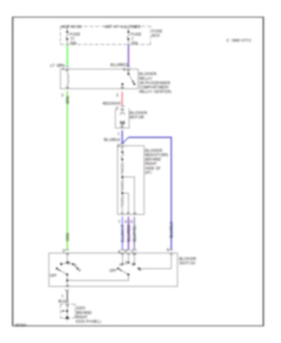
Heater Wiring Diagram for Hyundai Scoupe 1995
List of elements for Heater Wiring Diagram for Hyundai Scoupe 1995:
- Blower motor
- Blower relay (in passenger compartment relay center)
- Blower resistors (behind right side of i/p)
- Blower switch
- C 1995 vftc
- Fuse 20a
- Fuse 30a
- Fuse box
- G203 (behind right kick panel)
- Hot at all times
- Hot in on
- Off
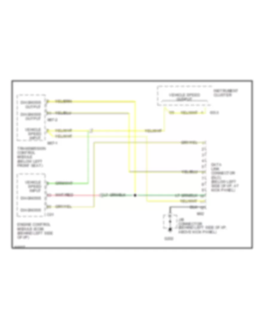
COMPUTER DATA LINES
Computer Data Lines, Early Production for Hyundai Scoupe 1995
List of elements for Computer Data Lines, Early Production for Hyundai Scoupe 1995:
- C01
- Data link connector (dlc) (below left side of i/p, at kick panel)
- Diagnosis
- Diagnosis output
- Engine control module (ecm) (behind left side of i/p)
- G202
- I05-3
- I06
- Instrument cluster
- J/b connector (behind left side of i/p, above kick panel)
- M02
- M07-1
- M07-2
- Transmission control module (below left front seat)
- Vehicle speed input
- Vehicle speed output
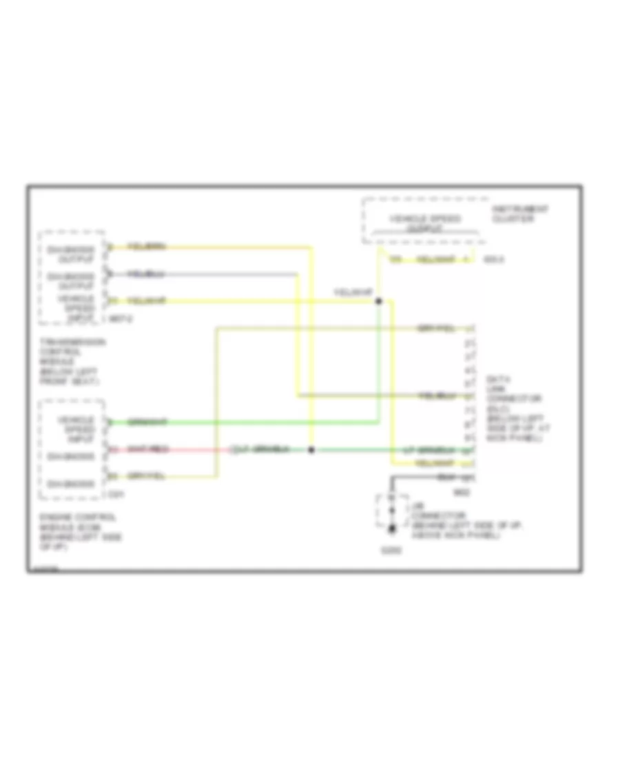
Computer Data Lines, Late Production for Hyundai Scoupe 1995
List of elements for Computer Data Lines, Late Production for Hyundai Scoupe 1995:
- C01
- Data link connector (dlc) (below left side of i/p, at kick panel)
- Diagnosis
- Diagnosis output
- Engine control module (ecm) (behind left side of i/p)
- G202
- I05-3
- I06
- Instrument cluster
- J/b connector (behind left side of i/p, above kick panel)
- M02
- M07-2
- Transmission control module (below left front seat)
- Vehicle speed input
- Vehicle speed output
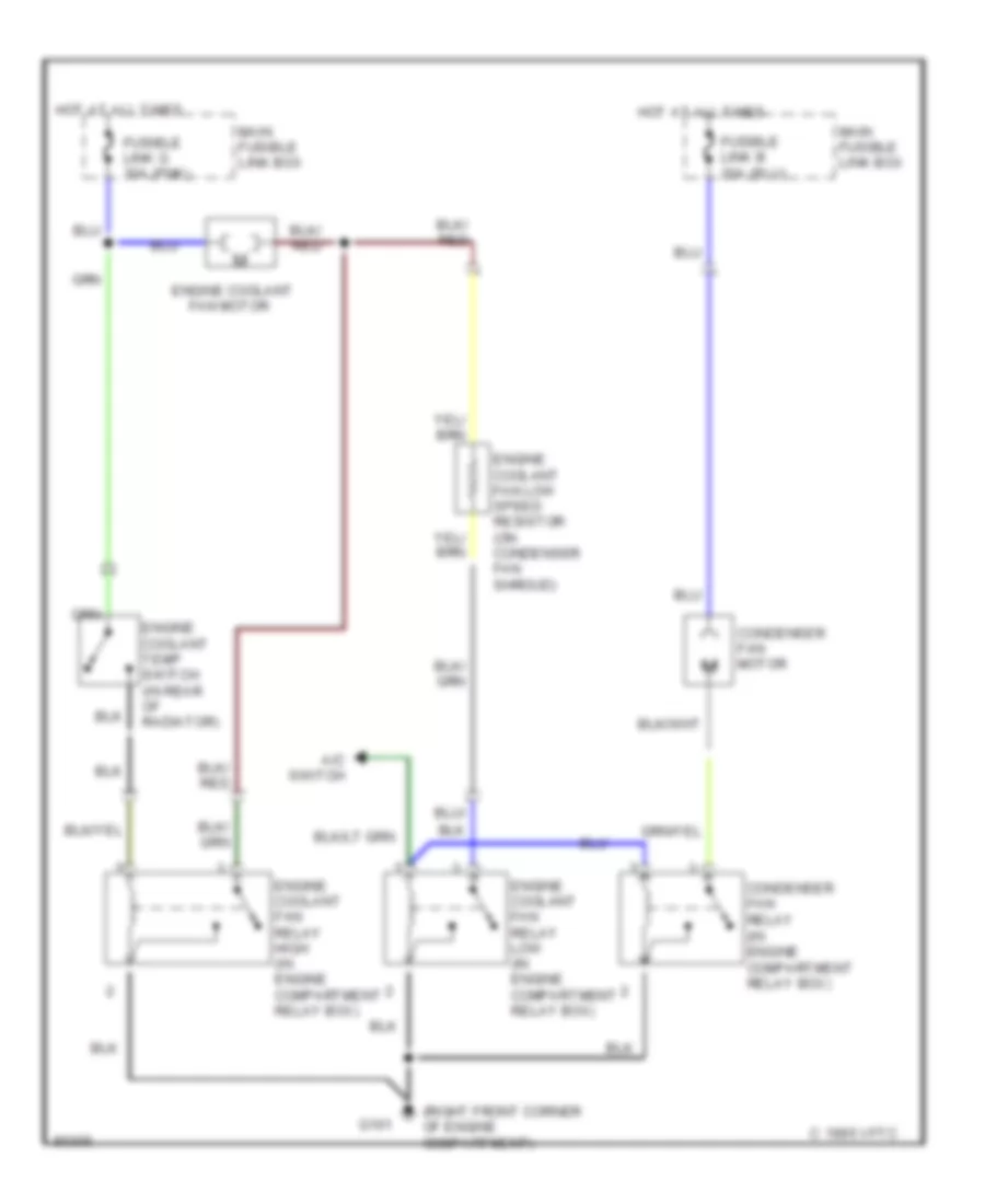
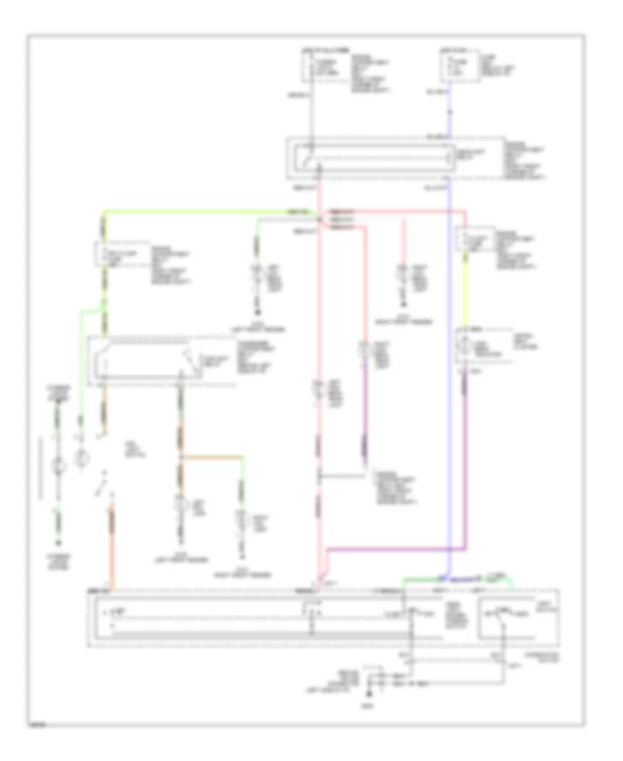
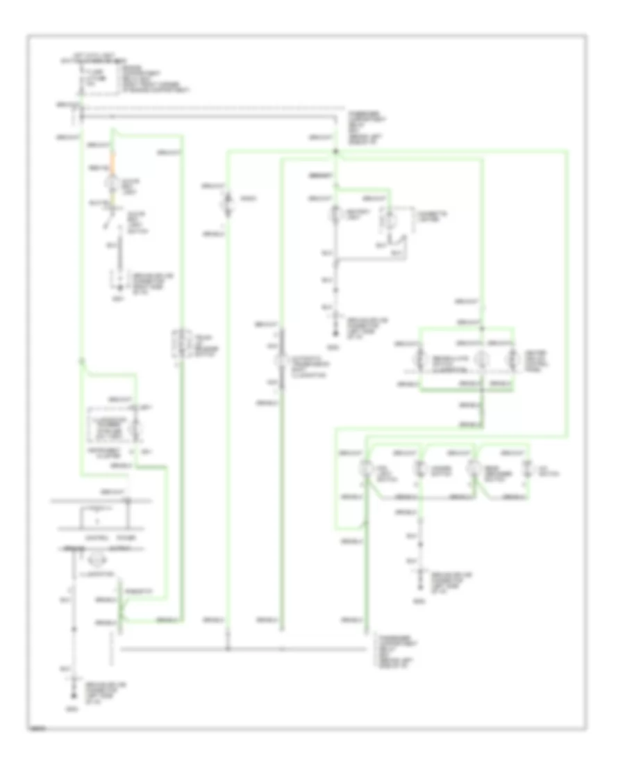
COOLING FAN
Cooling Fan Wiring Diagram for Hyundai Scoupe 1995
List of elements for Cooling Fan Wiring Diagram for Hyundai Scoupe 1995:
- (right front corner of engine compartment)
- A/c switch
- C 1995 vftc
- Condenser fan motor
- Condenser fan relay (in engine compartment relay box)
- Engine coolant
- Engine coolant fan low speed resistor (on condenser fan shroud)
- Engine coolant fan relay high (in engine compartment relay box)
- Engine coolant fan relay low (in engine compartment relay box)
- Engine coolant temp switch (in rear of radiator)
- Fan motor
- Fusible link g 30a (pnk)
- G101
- Hot at all times
- Main fusible link box
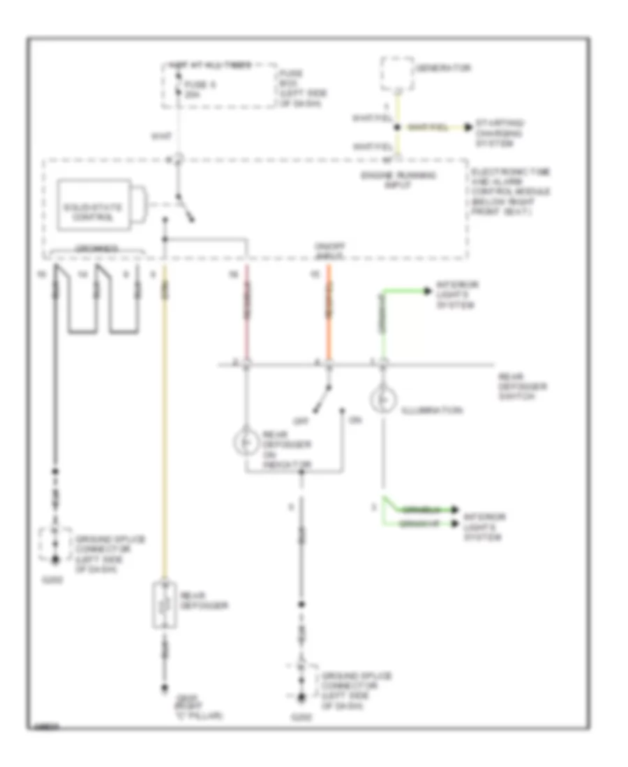
DEFOGGERS
Defogger Wiring Diagram for Hyundai Scoupe 1995
List of elements for Defogger Wiring Diagram for Hyundai Scoupe 1995:
- (right "c" pillar)
- Electronic time and alarm control module (below right front seat)
- Engine running input
- Fuse 6 20a
- Fuse box (left side of dash)
- G202
- G905
- Generator
- Ground splice connector (left side of dash)
- Grounds
- Hot at all times
- Illumination
- Interior lights system
- Off
- On/off input
- Rear defogger
- Rear defogger on indicator
- Rear defogger switch
- Solid-state control
- Starting/ charging system
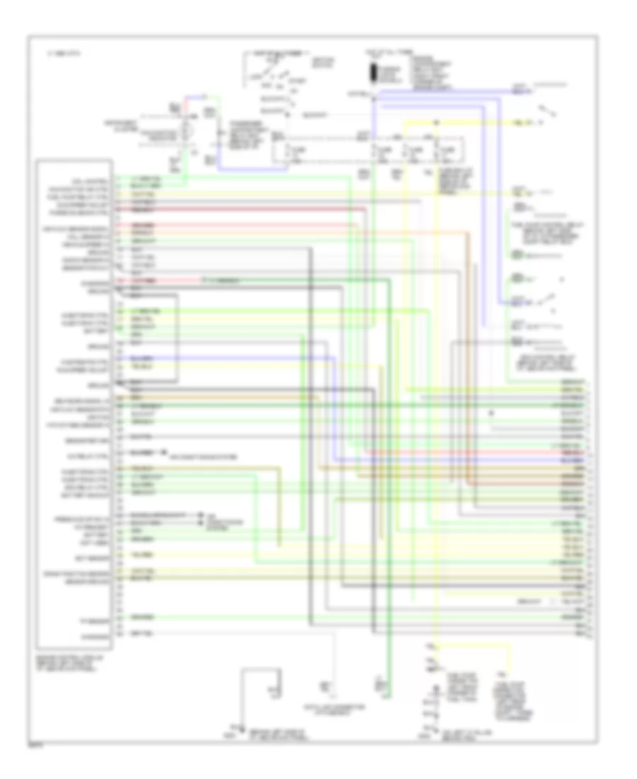
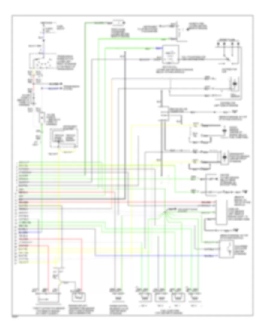
ENGINE PERFORMANCE
1.5L
1.5L Turbo, Engine Performance Wiring Diagrams (1 of 2) for Hyundai Scoupe 1995
List of elements for 1.5L Turbo, Engine Performance Wiring Diagrams (1 of 2) for Hyundai Scoupe 1995:
- (behind left side of i/p, above kick panel)
- (behind left side of i/p, in passenger compt relay box)
- (i/p fuse box)
- (not used)
- (on left "c" pillar, behind trim)
- A/c relay ctrl
- A/c request
- Acc
- Air conditioning system
- Air flow sensor rtn
- Air flow sensor signal
- Battery
- Battery backup
- C 1995 vftc
- Cluster
- Coil control
- Compt, taped to harness)
- Crank position sensor
- Data link connector
- Diagnosis
- Ecm control relay
- Ecm relay ctrl
- Ect sensor
- Engine compartment relay box (right front corner of engine compt)
- Engine control module (behind left side of i/p, above kick panel)
- Fuel pump (inside top left front corner of fuel tank)
- Fuel pump control relay
- Fuel pump inspection connector (left rear of engine
- Fuel pump relay ctrl
- Fuse 10a
- Fuse box:i/p (behind left side of i/p, above kick panel)
- G200
- G302
- Ground
- Hall sensor in
- Hot at all times
- Htd oxygen sensor in
- Idle speed adjust
- Ig1
- Ignition
- Ignition switch
- Injector #1 ctrl
- Injector #2 ctrl
- Injector #3 ctrl
- Injector #4 ctrl
- Instrument
- Knock sensor in
- Lock
- Malfunction ind ctrl
- Malfunction indicator
- Passenger compartment relay box (behind left side of i/p)
- Press & evap sw in
- Purge solenoid ctrl
- Self-burn signal in
- Sensor ground
- Sensor pwr out
- Sensor return
- Start
- Tp sensor
- Vehicle speed in
- Wastegate ctrl
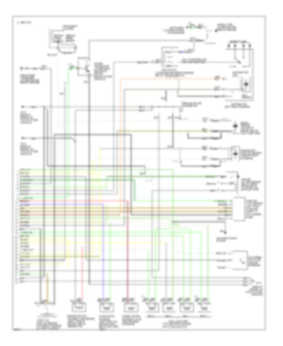
1.5L Turbo, Engine Performance Wiring Diagrams (2 of 2) for Hyundai Scoupe 1995
List of elements for 1.5L Turbo, Engine Performance Wiring Diagrams (2 of 2) for Hyundai Scoupe 1995:
-
- (left side of engine)
- (lower center rear of engine, below intake manifold)
- (rear of
- (top center of engine,
- 0.8
- 12k
- Air conditioning system
- C 1995 vftc
- Coil-to-distributor high voltage wire
- Crankshaft position sensor (center front
- Distributor
- Distributor cap
- Engine coolant temperature sensor (right side of engine, above generator)
- Engine, below) fuel injectors)
- Engine, on
- Fuel injectors
- G115
- G115 (rear of engine, on top of intake manifold)
- Ground splice connector
- Hall sensor
- Heated oxygen sensor (below rear of engine, on exhaust pipe)
- Idle speed actuator (center of engine)
- Ignition coil
- Instrument cluster
- Instrument cluster system (tachometer)
- Knock sensor (center of
- Manifold)
- Mass air flow sensor (left front
- Nca
- No. 1
- No. 2
- No. 3
- No. 4
- Noise filter (lower center rear of engine)
- Of engine compt, in air cleaner hose)
- Of engine)
- On intake manifold)
- Power transistor (lower rear center of engine, behind intake manifold)
- Purge control solenoid valve (center rear of engine)
- Radio noise condenser (lower center rear of engine)
- Red
- Spark plugs
- Throttle position sensor (top rear of engine, on throttle body)
- Top of intake
- Vehicle speed output
- Vehicle speed sensor
- Waste-gate solenoid (left front of engine compt, below battery tray)
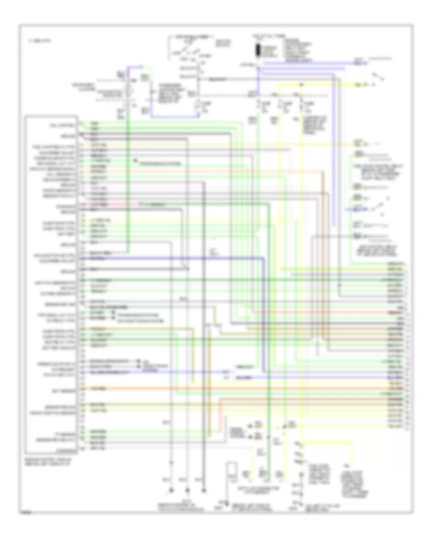
1.5L, Engine Performance Wiring Diagrams (1 of 2) for Hyundai Scoupe 1995
List of elements for 1.5L, Engine Performance Wiring Diagrams (1 of 2) for Hyundai Scoupe 1995:
- (behind left side of i/p, above kick panel)
- (behind left side of i/p, in passenger compt relay box)
- (i/p fuse box)
- (on left "c" pillar, behind trim)
- (rear of engine, on top of intake manifold)
- A/c relay ctrl
- A/c request
- A/t
- A/t only
- Acc
- Air conditioning system
- Air flow sensor rtn
- Air flow sensor signal
- Battery
- Battery backup
- C 1995 vftc
- Cluster
- Coil control
- Compt, taped to harness)
- Crank position sensor
- Data link connector
- Diagnosis
- Ecm control relay
- Ecm relay ctrl
- Ect sensor
- Engine compartment relay box (right front corner of engine compt)
- Engine control module (behind left side of i/p)
- Fuel pump (inside top left front corner of fuel tank)
- Fuel pump control relay
- Fuel pump inspection connector (left rear of engine
- Fuel pump relay ctrl
- Fuse 10a
- Fuse box:i/p (behind left side of i/p, above kick panel)
- G115
- G200
- G302
- Ground
- Hall sensor in
- Hot at all times
- Idle speed adjust
- Ig1
- Ignition
- Ignition switch
- Injector #1 ctrl
- Injector #2 ctrl
- Injector #3 ctrl
- Injector #4 ctrl
- Instrument
- Knock sensor in
- Lock
- M/t
- M/t only
- Malfunction ind ctrl
- Malfunction indicator
- Oxygen sensor in
- P/n (a/t)-bat (m/t)
- Passenger compartment relay box (behind left side of i/p)
- Press & evap sw in
- Purge solenoid ctrl
- Rpm signal out (a/t)
- Sensor ground
- Sensor pwr out
- Sensor return
- Sensor return (a/t)
- Start
- Tp sensor
- Tps signal out (a/t)
- Trans- mission system
- Transmission system
- Vehicle speed in
1.5L, Engine Performance Wiring Diagrams (2 of 2) for Hyundai Scoupe 1995
List of elements for 1.5L, Engine Performance Wiring Diagrams (2 of 2) for Hyundai Scoupe 1995:
-
- (behind i/p,
- (left side of engine)
- (lower center rear of engine, below intake manifold)
- (lower left front of engine, in top front of transmission)
- (rear of engine, on top of intake manifold)
- (top center of engine)
- (top rear of engine, on throttle body)
- 0.8
- 12k
- A/t
- Air conditioning system
- Coil-to-distributor high voltage wire
- Crankshaft position sensor (center front
- Distributor
- Distributor cap
- Engine compt, in air cleaner hose)
- Engine coolant temperature sensor (right side of engine, above generator)
- Engine, below) fuel injectors)
- Fuel injectors
- Fuse 9 10a
- Fuse box:i/p
- G115
- Ground splice connector
- Hall sensor
- Heated oxygen sensor (below rear of engine, on exhaust pipe)
- Hot in on
- Idle speed actuator (center of engine)
- Ignition coil
- In-line diode a (behind i/p, taped to harness)
- In-line diode b
- Instrument cluster
- Instrument cluster system (tachometer)
- Knock sensor (center of
- M/t
- Mass air flow sensor (left rear of
- Nca
- No. 1
- No. 2
- No. 3
- No. 4
- Noise filter (lower center rear of engine)
- Of engine)
- Only
- Purge control solenoid valve (center rear of engine)
- R
- Radio noise condenser (lower center rear of engine)
- Red
- Spark plugs
- Taped to harness)
- Throttle position sensor
- Transmission range switch
- Transmission system
- Vehicle speed output
- Vehicle speed sensor
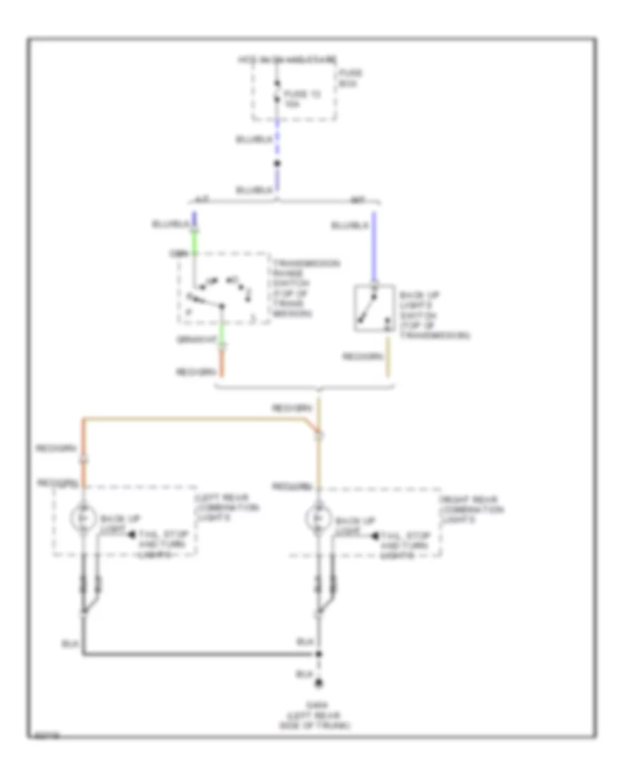
EXTERIOR LIGHTS
Back-up Lamps Wiring Diagram for Hyundai Scoupe 1995
List of elements for Back-up Lamps Wiring Diagram for Hyundai Scoupe 1995:
- (left rear
- A/t
- Back up light
- Back up lights switch (top of transmission)
- Fuse 13 10a
- Fuse box
- G404
- Hot in on and start
- Left rear combination lights
- M/t
- Right rear combination lights
- Side of trunk)
- Tail, stop and turn lights
- Transmission range switch (top of trans mission)
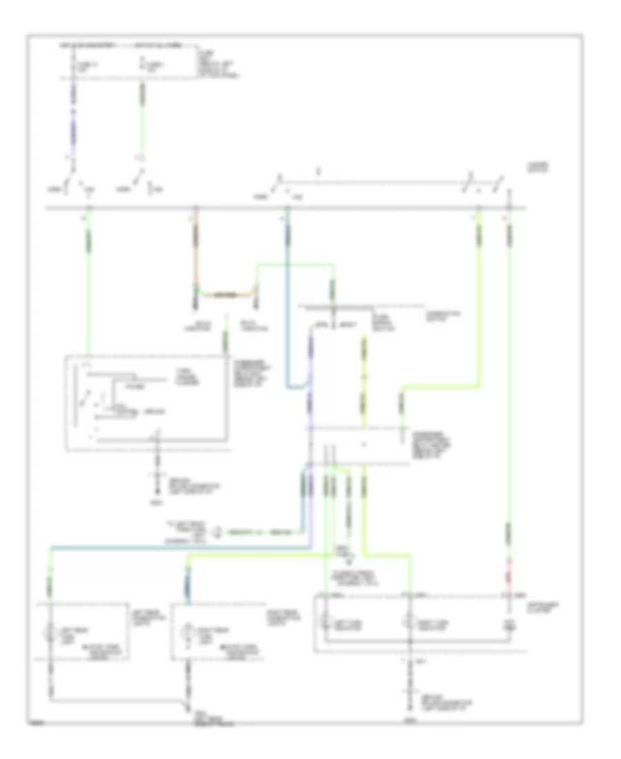
Exterior Lamps Wiring Diagram (1 of 2) for Hyundai Scoupe 1995
List of elements for Exterior Lamps Wiring Diagram (1 of 2) for Hyundai Scoupe 1995:
- (left front fender)
- (left "c" pillar)
- (left rear side of trunk)
- (right front fender)
- Back up lights
- Brake pedal switch (top of brake pedal support bracket)
- Combination switch
- Dash fuse box
- Digital clock
- Engine compartment relay box
- Engine compartment relay box (right front corner of engine compartment)
- From passenger compartment relay box (diagram 2 of 2)
- Fuse 4 15a
- G100
- G101
- G202
- G404
- G904
- Ground splice connector (left side
- Head
- High mount stop light
- Hot at all times
- Inside tail/stop light
- Interior lights system
- Left front park/turn light
- Left license light
- Left rear combination lights
- Left t/lamp fuse 10a
- Light switch
- Nca
- Of i/p)
- Off
- Outside tail/stop light
- Outside taillight
- Park
- Passenger compartment relay box (behind left side of i/p)
- Red
- Right front park/turn light
- Right license light
- Right rear combination lights
- Right t/lamp fuse 10a
- Shift interlock system
- Taillight relay
- Turn lights
Exterior Lamps Wiring Diagram (2 of 2) for Hyundai Scoupe 1995
List of elements for Exterior Lamps Wiring Diagram (2 of 2) for Hyundai Scoupe 1995:
- (diagram 1 of 2)
- (left rear side of trunk)
- Build variation
- Coil control
- Combination switch
- Fuse 13 10a
- Fuse 3 10a
- Fuse box (below left side of i/p, at kick panel)
- G202
- G404
- Ground
- Ground splice connector (left side of i/p)
- Haz
- Hazard switch
- Hot at all times
- Hot in on and start
- I05-1
- I05-2
- I05-3
- Instrument cluster
- Left
- Left rear combination lights
- Left rear turn light
- Left turn indicator
- Nca
- Norm
- Not used
- Passenger compartment relay box (behind left side of i/p)
- Passenger compartment relay center (behind left side of i/p)
- Power
- Red
- Right
- Right rear combination lights
- Right rear turn light
- Right turn indicator
- Stop, park and backup lights
- To left front park/turn light (diagram 1 of 2)
- To right front park/turn light
- Turn signal switch
- Turn/ hazard flasher
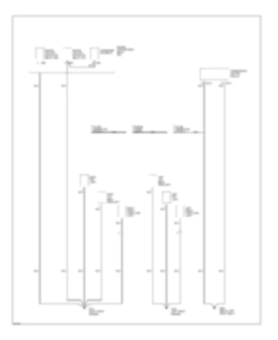
GROUND DISTRIBUTION
Ground Distribution Wiring Diagram (1 of 4) for Hyundai Scoupe 1995
List of elements for Ground Distribution Wiring Diagram (1 of 4) for Hyundai Scoupe 1995:
- Condenser fan relay
- E05
- E08
- E09
- Engine compartment relay box
- Engine coolant fan motor relay high
- Engine coolant fan motor relay low
- Engine speed shield
- G100 (left front fender)
- G101 (right front fender)
- G300 (below left front seat)
- Left fog light
- Left front park/turn light
- Left low beam headlight
- M07-1
- M07-2
- Nca
- Pulse generator a shield
- Pulse generator b shield
- Right fog light
- Right front park/turn light
- Right low beam headlight
- Transmission control module
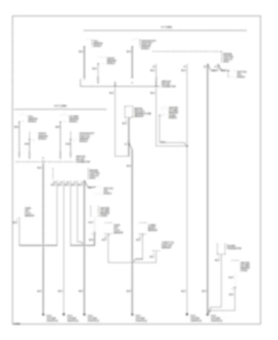
Ground Distribution Wiring Diagram (2 of 4) for Hyundai Scoupe 1995
List of elements for Ground Distribution Wiring Diagram (2 of 4) for Hyundai Scoupe 1995:
- Crankshaft position sensor shield
- Engine control module (ecm)
- Engine coolant temperature sensor
- G131 (intake manifold)
- Ground splice connector
- Hall sensor shield
- Heated oxygen sensor (ho2s)
- Heated oxygen sensor (ho2s) shield
- Ignition coil shield
- Knock sensor shield
- Mass air flow sensor
- Nca
- Oxygen sensor shield
- Power transistor
- Throttle position sensor
- Turbo boost sensor
- W/ turbo
- W/o turbo
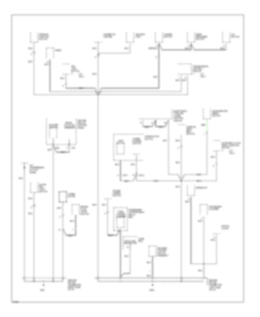
Ground Distribution Wiring Diagram (3 of 4) for Hyundai Scoupe 1995
List of elements for Ground Distribution Wiring Diagram (3 of 4) for Hyundai Scoupe 1995:
- A/c compressor clutch diode
- A/c switch
- Accelerator pedal switch
- Ashtray light
- Blower switch
- Brake fluid level switch
- Cigarette lighter
- Combination switch
- Data link connector
- Digital clock
- Driver's master switch assembly
- Electronic time and alarm control module
- Fuse box
- G201
- G202
- Glove box light switch
- Ground splice connector (left side of i/p)
- Ground splice connector (right side of i/p)
- Hazard switch
- Heater and a/c control panel
- Instrument cluster
- Key lock switch
- Light switch
- M/t only
- M37-1
- M37-2
- M39
- M70
- Parking position switch
- Passenger compartment relay box
- Passive seat belt switch
- Power mirror switch
- Radio
- Rear defogger switch
- Recir- culation indicator
- Rheostat
- Starter clutch pedal position switch
- Transmission control module
- Turn/ hazard flasher
- Wiper motor
- Wiper/ washer switch
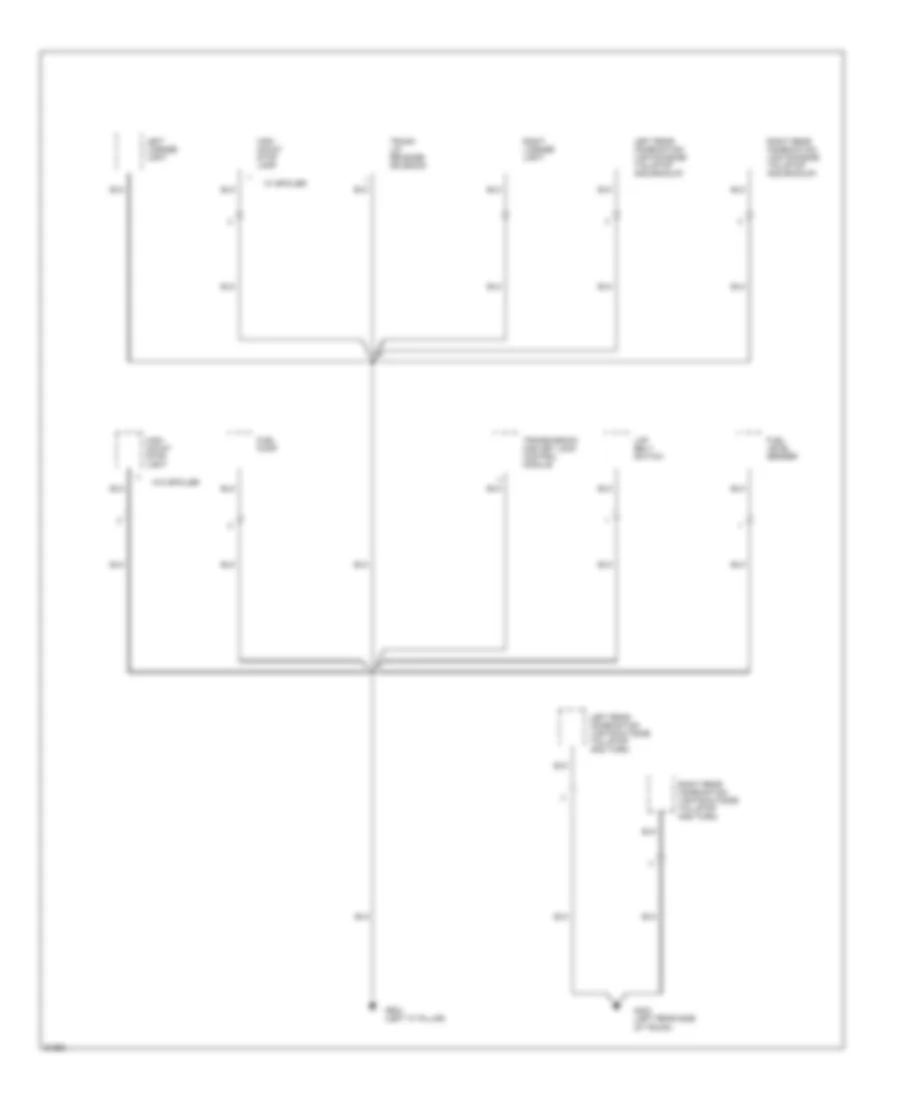
Ground Distribution Wiring Diagram (4 of 4) for Hyundai Scoupe 1995
List of elements for Ground Distribution Wiring Diagram (4 of 4) for Hyundai Scoupe 1995:
- Fuel level sender
- Fuel pump
- G404 (left rear side of trunk)
- G904 (left "c" pillar)
- High mount stop lamp
- High mount stop light
- Lap belt switch
- Left license light
- Left rear combination lights(inside tail/stop and backup)
- Left rear combination lights(outside tail,stop and turn)
- Right license light
- Right rear combination lights(inside tail/stop and backup)
- Right rear combination lights(outside tail,stop and turn)
- Transmission and key lock control module
- Trunk lid release solenoid
- W/ spoiler
- W/o spoiler
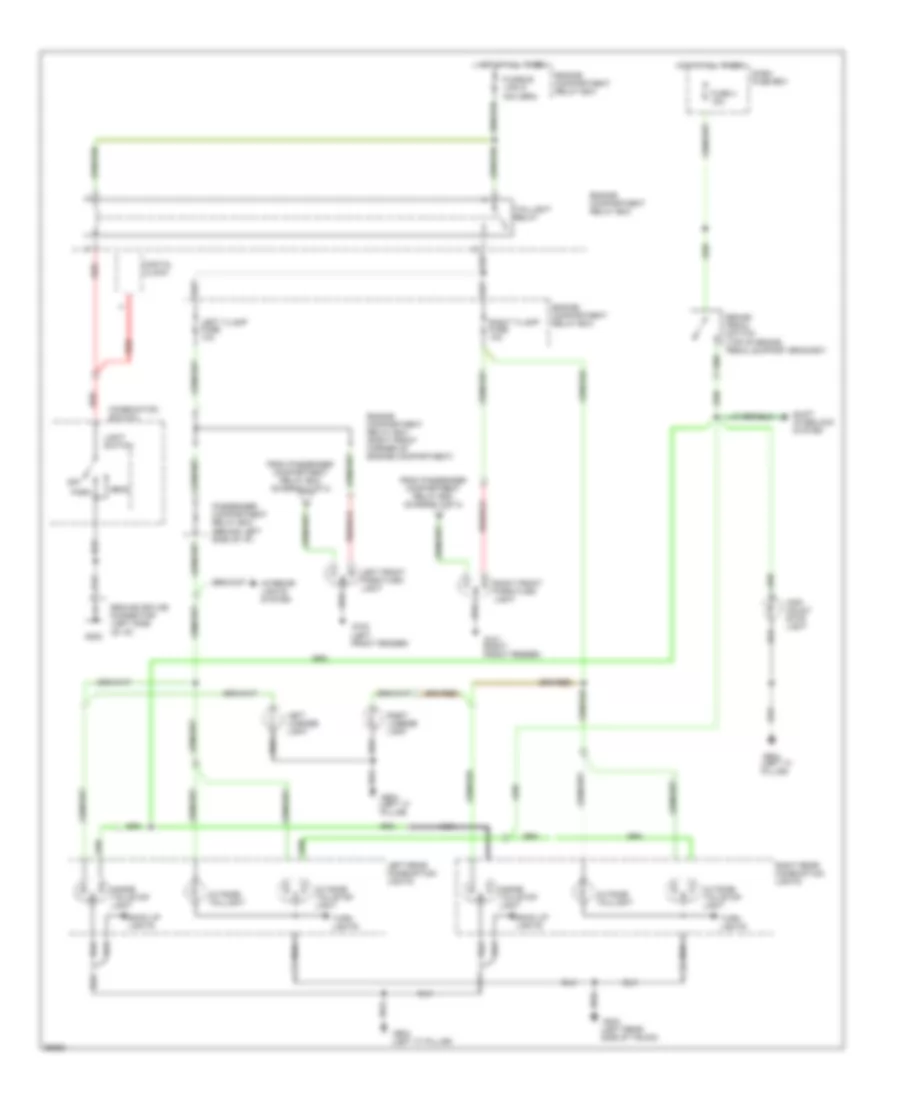
HEADLIGHTS
Headlight Wiring Diagram for Hyundai Scoupe 1995
List of elements for Headlight Wiring Diagram for Hyundai Scoupe 1995:
- (left side of i/p)
- Combination switch
- Engine compartment relay box (right front corner of engine compt.)
- Flash
- Fog light switch
- Foglight relay
- Frt f/lamp fuse 15a
- Fuse 20a
- Fuse box (below left side of i/p)
- G100 (left front fender)
- G101 (right front fender)
- G202
- Ground splice connector
- H/light fuse 10a
- Head
- Head- light dimmer/ passing switch
- Headlight relay
- High
- High beam indicator
- Hot at all times
- Hot in on
- I05-2
- I05-3
- Instru- ment cluster
- Interior lights system
- Left fog lamp
- Left high beam head- light
- Left low beam head- light
- Light switch
- Low
- M37-1
- Off
- Park
- Passenger compartment relay box (behind left side of i/p)
- Right fog lamp
- Right high beam head- light
- Right low beam head- light
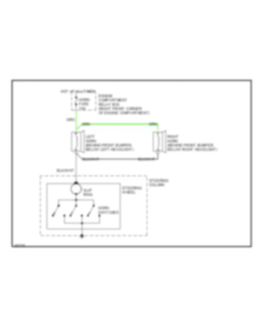
HORN
Horn Wiring Diagram for Hyundai Scoupe 1995
List of elements for Horn Wiring Diagram for Hyundai Scoupe 1995:
- Engine compartment relay box (right front corner of engine compartment)
- Horn fuse 10a
- Horn switches
- Hot at all times
- Left horn (behind front bumper, below left headlight)
- Right horn (behind front bumper, below right headlight)
- Slip ring
- Steering column
- Steering wheel
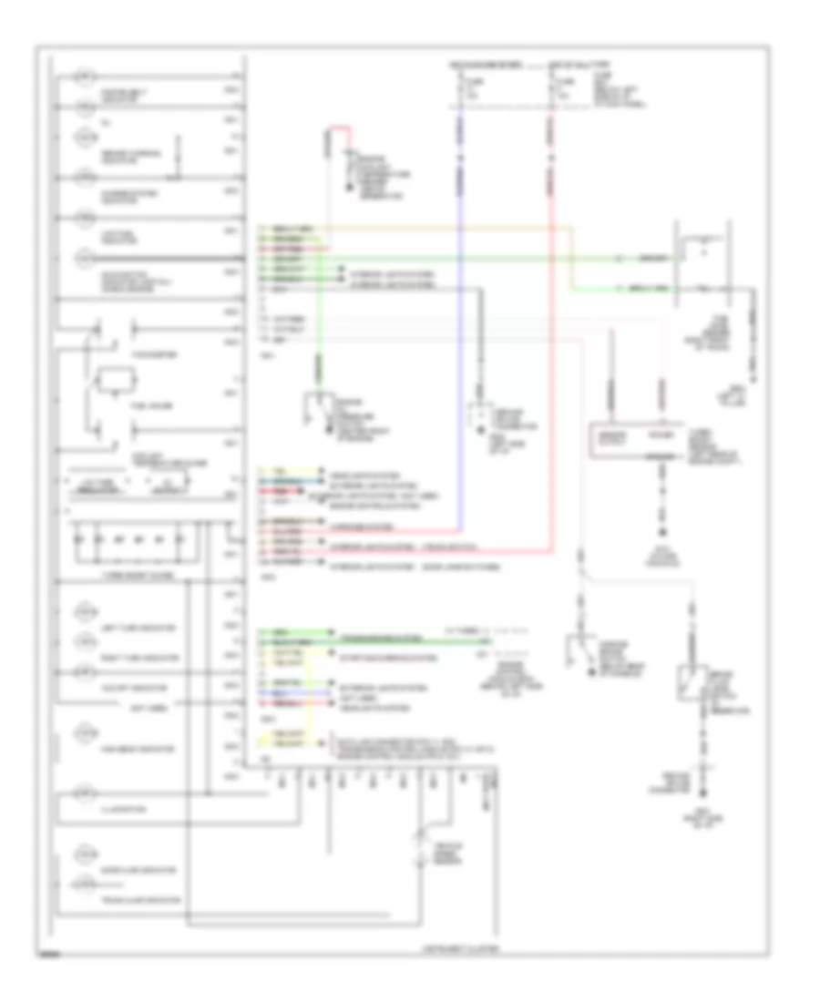
INSTRUMENT CLUSTER
Instrument Cluster Wiring Diagram for Hyundai Scoupe 1995
List of elements for Instrument Cluster Wiring Diagram for Hyundai Scoupe 1995:
- "brake" warning indicator
- "o/d off" indicator
- (door jamb switches)
- (not used)
- (not used) i05-3
- (trunk switch)
- 5v output
- Brake fluid level switch (in reservoir)
- C01
- Charge system indicator
- Coolant temperature guage
- Data link connector (pin 11, m02) transmission control module (pin 10, m07-2) engine control module (pin 9, c01)
- Door ajar indicator
- Engine control module (ecm) (behind left side of i/p)
- Engine controls system
- Engine coolant temperature sender (above generator)
- Engine oil pressure switch (center front of engine)
- Exterior lights system
- Fasten belt indicator
- Fuel gauge
- Fuel level sender (right front of trunk)
- Fuse 10a
- Fuse box (below left side of i/p, at kick panel)
- G131 (intake manifold)
- G201 (right side of i/p)
- G202 (left side of i/p)
- G904 (left "c" pillar)
- Ground
- Ground splice connector
- Headlights system
- High beam indicator
- Hot at all times
- Hot in on and start
- I05-1
- I05-2
- I05-3
- I06
- Illumination
- Instrument cluster
- Interior lights system
- Left turn indicator
- Low fuel indicator
- Malfunction indicator lamp (mil) (check engine)
- Oil
- Parking brake switch (below rear of console)
- Power
- Red
- Right turn indicator
- Sensor output
- Starting/charging system
- Tachometer
- Transmissions system
- Trunk ajar indicator
- Turbo boost guage
- Turbo boost sensor (left rear of engine compt.)
- Vehicle speed sensor
- Voltage regulator
- W/ turbo)
- Warnings system
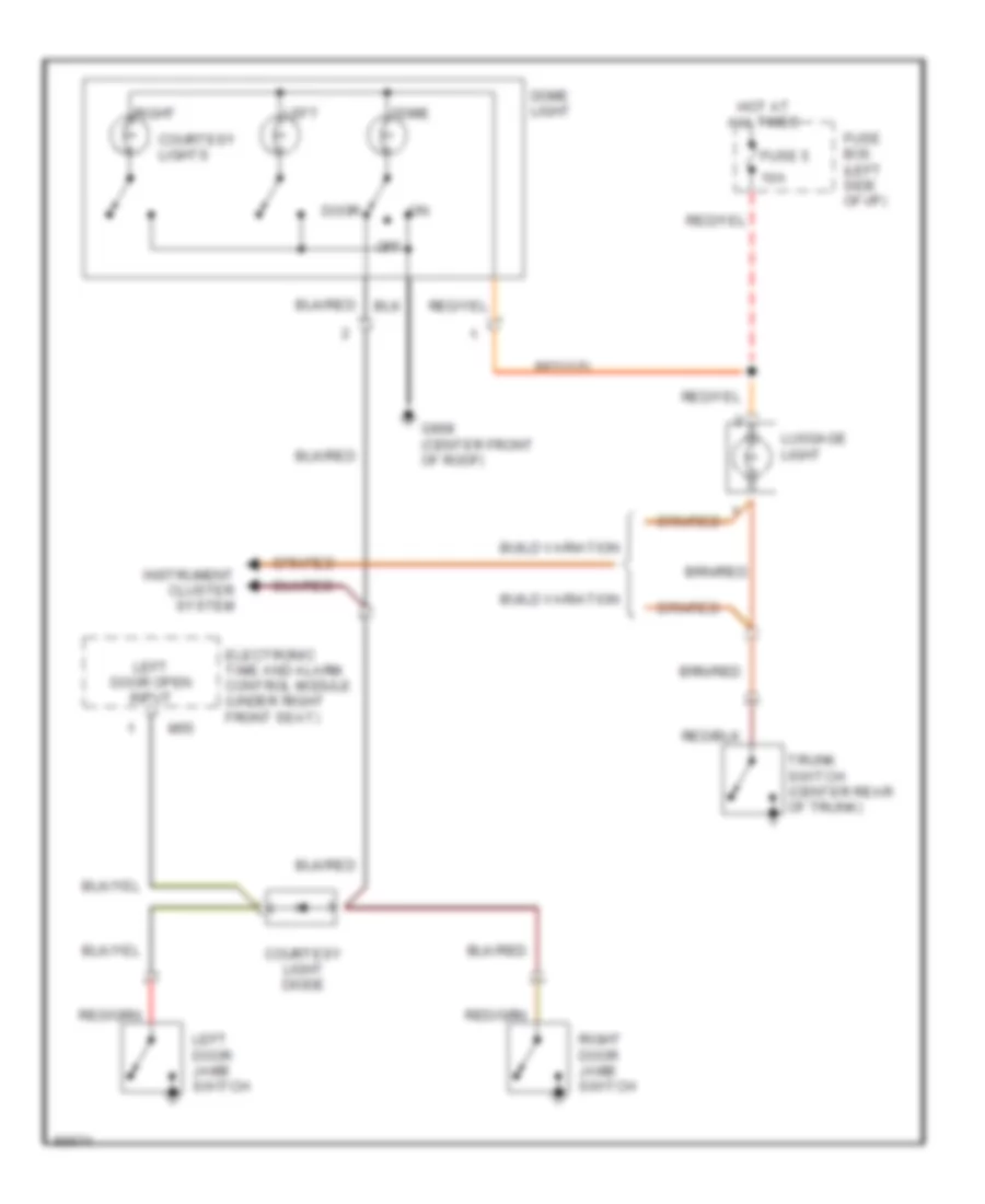
INTERIOR LIGHTS
Courtesy Lamps Wiring Diagram for Hyundai Scoupe 1995
List of elements for Courtesy Lamps Wiring Diagram for Hyundai Scoupe 1995:
- 10a
- Build variation
- Courtesy light diode
- Courtesy lights
- Dome
- Dome light
- Door
- Electronic time and alarm control module (under right front seat)
- Fuse 5
- Fuse box (left side of i/p)
- G908 (center front of roof)
- Hot at all times
- Instrument cluster system
- Left
- Left door jamb switch
- Left door open input
- Luggage light
- M55
- Off
- Right
- Right door jamb switch
- Trunk switch (center rear of trunk)
Instrument Illumination Wiring Diagram for Hyundai Scoupe 1995
List of elements for Instrument Illumination Wiring Diagram for Hyundai Scoupe 1995:
- A/c switch
- Ashtray light
- Automatic transmission shift illumination
- Cigarette lighter
- Control
- Engine compartment relay box (right front corner of engine compartment)
- Fog light switch
- G201
- G202
- Glove box light
- Glove box light switch
- Ground
- Ground splice connector (left side of i/p)
- Ground splice connector (right side of i/p)
- Hazard switch
- Heater and a/c control panel
- Hot with light switch in park or head
- I05-1
- Illumination
- Illumination (number) of bulbs may vary)
- Instrument cluster
- Nca
- Output
- Passenger compartment relay box (behind left side of i/p)
- Power
- Radio
- Rear defogger switch
- Recirculate switch illumination
- Rheostat
- T/lamp lh fuse 10a
- Trunk lid release switch
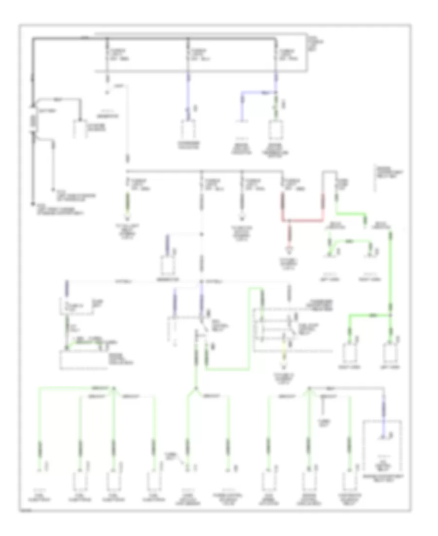
POWER DISTRIBUTION
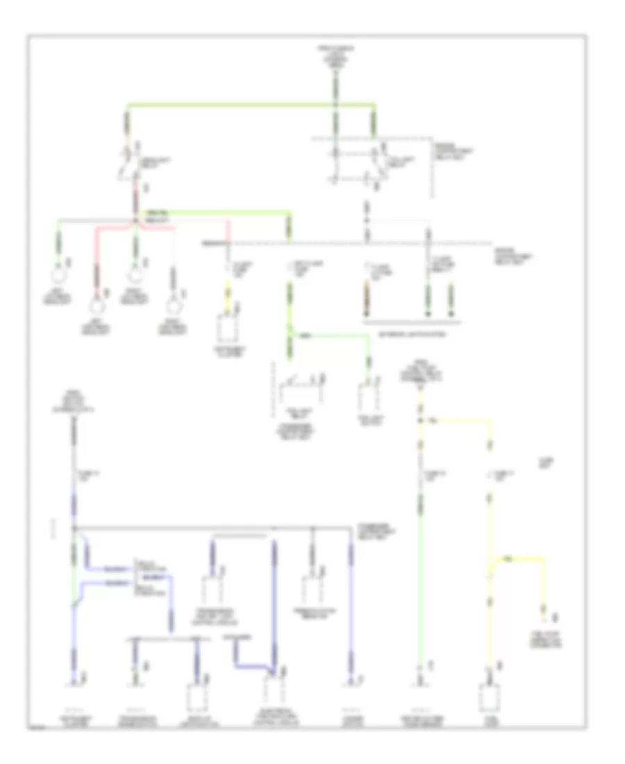
Power Distribution Wiring Diagram (1 of 4) for Hyundai Scoupe 1995
List of elements for Power Distribution Wiring Diagram (1 of 4) for Hyundai Scoupe 1995:
- (non-turbo)
- (pnk)
- (red)
- (turbo)
- 20a
- 50a
- A/c control relay
- Battery
- Build variation
- C01
- C06
- C11
- C14-1
- C14-2
- C14-3
- C14-4
- C15
- C32
- Condenser fan motor
- E07
- E19
- E23
- E25
- E26-1
- E33
- Ecm control relay
- Engine compartment relay box
- Engine control module (ecm)
- Engine coolant temperature switch
- Engine coolant fan motor
- Fuel injector #1
- Fuel injector #2
- Fuel injector #3
- Fuel injector #4
- Fuel pump control relay
- Fuse 16 10a
- Fuse box
- Fusible link a
- Fusible link b
- Fusible link c 30a
- Fusible link d 40a
- Fusible link e 20a
- Fusible link f 50a
- Fusible link g 30a
- G100 (left front corner of engine compartment)
- G112 (left side of engine on transaxle)
- Generator
- Horn fuse 10a
- Idle speed actuator
- Left horn
- M/t only
- M03
- M28
- Main fusible link box
- Mass air flow (maf) sensor
- Nca
- Passenger compartment relay box
- Purge control solenoid valve
- Right horn
- Starter solenoid
- To fuse 1 (diagram 3 of 4)
- To fuse 15 (diagram 4 of 4)
- To ignition switch (diagram 2 of 4)
- To taillight relay (diagram 4 of 4)
- Turbo only
- Wastegate solenoid relay
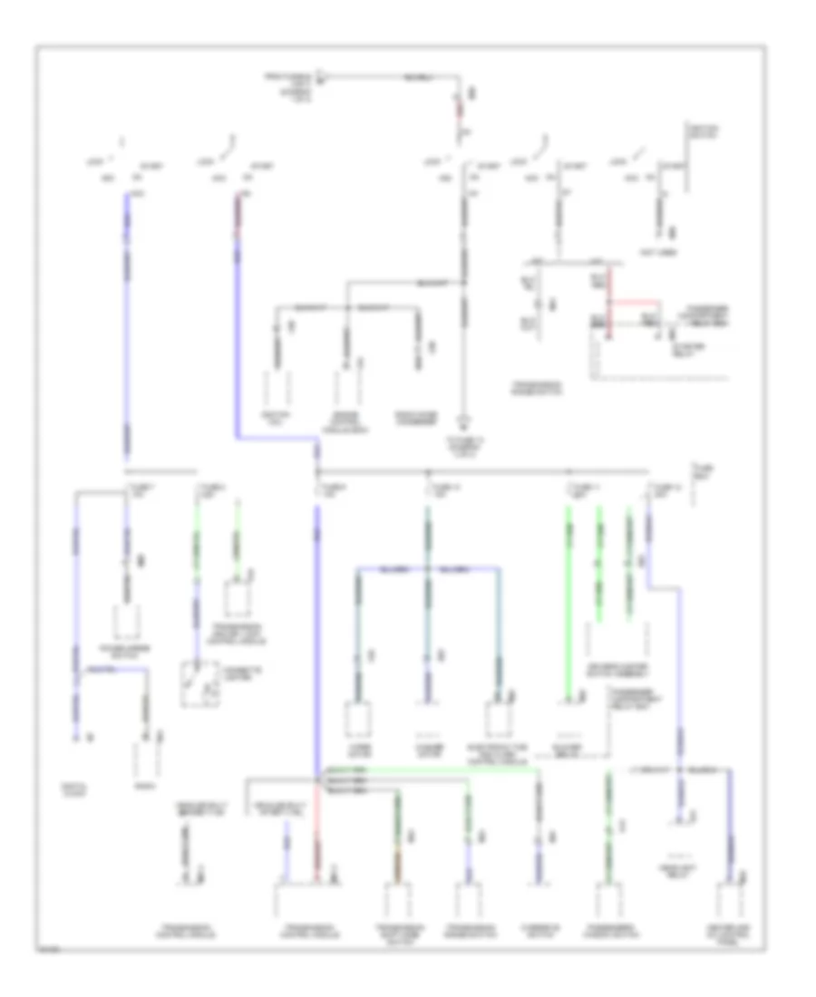
Power Distribution Wiring Diagram (2 of 4) for Hyundai Scoupe 1995
List of elements for Power Distribution Wiring Diagram (2 of 4) for Hyundai Scoupe 1995:
- (not used)
- 1g1
- A/t
- Acc
- Blower relay
- C01
- C02
- C08
- C09
- Cigarette lighter
- D03
- D13
- Digital clock
- Driver's master switch assembly
- E03
- E31
- Electronic time and alarm control module
- Engine control module (ecm)
- From fusible link c (diagram 1 of 4)
- Fuse 10 15a
- Fuse 11 20a
- Fuse 12 20a
- Fuse 7 10a
- Fuse 8 15a
- Fuse 9 10a
- Fuse box
- Headlight relay
- Heater and a/c control panel
- I07
- Ig2
- Ignition coil
- Ignition switch
- Lock
- M/t
- M07-2
- M07-3
- M08
- M24
- M29 starter relay
- M32
- M36
- M41
- M43
- M47
- M55
- M70
- On acc
- Overdrive switch
- Passenger compartment relay box
- Passenger's window switch
- Power mirror switch
- R16
- Radio
- Radio noise condenser
- Red
- Start
- To fuse 13 (diagram 4 of 4)
- Transmission and key lock control module
- Transmission control module
- Transmission range swiitch
- Transmission range switch
- Transmission shift mode switch
- Vehicles built after 7/1/93
- Vehicles built before 7/1/93
- Washer motor
- Wiper motor
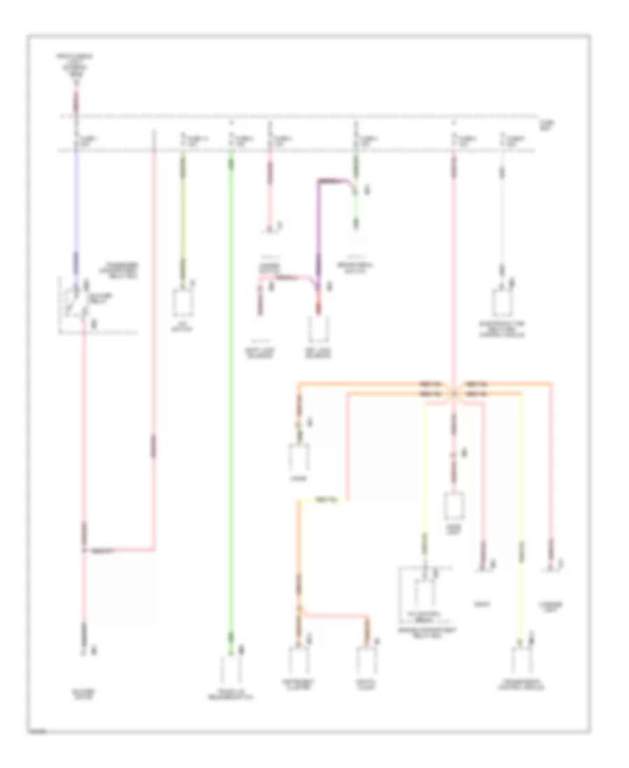
Power Distribution Wiring Diagram (3 of 4) for Hyundai Scoupe 1995
List of elements for Power Distribution Wiring Diagram (3 of 4) for Hyundai Scoupe 1995:
- A/c control relay
- A/c switch
- Blower motor
- Blower relay
- Brake pedal switch
- Chime
- Digital clock
- Dome light
- E07
- Electronic time and alarm control module
- Engine compartment relay box
- From fusible link f (diagram 1 of 4)
- Fuse 1 30a
- Fuse 14 10a
- Fuse 2 15a
- Fuse 3 10a
- Fuse 4 15a
- Fuse 5 10a
- Fuse 6 20a
- Fuse box
- Hazard switch
- I05-2
- I07
- I13
- I15
- Instrument cluster
- Key lock solenoid
- Luggage light
- M07-2
- M09
- M11
- M12
- M32
- M34
- M41
- M46
- M51
- M55
- M57
- Passenger compartment relay box
- R11
- Radio
- Red
- Shift lock solenoid
- Transmission control module
- Trunk lid release switch
Power Distribution Wiring Diagram (4 of 4) for Hyundai Scoupe 1995
List of elements for Power Distribution Wiring Diagram (4 of 4) for Hyundai Scoupe 1995:
- (build variation)
- (not used)
- A/t
- Back up lights switch
- C19
- E06
- E16
- E17
- E29
- E30
- E31
- Electronic time and alarm control module
- Engine compartment relay box
- Exterior lights system
- Fog light relay
- Fog light switch
- From fuel pump control relay (diagram 1 of 4)
- From fusible link d (diagram 1 of 4)
- From ignition switch (diagram 2 of 4)
- Frt f/lamp fuse 15a
- Fuel pump
- Fuel pump inspection connector
- Fuse 13 10a
- Fuse 15 10a
- Fuse 17 10a
- Fuse box
- H/light fuse 10a
- Hazard switch
- Headlight relay
- Heated oxygen (ho2s) sensor
- I05-2
- I13
- I17
- Instrument cluster
- Left high beam headlight
- Left low beam headlight
- M/t
- M19
- M24
- M25
- M55
- M70
- Nca
- Passenger compartment relay box
- Pre-excitation resistor
- R05
- R16
- Right high beam headlight
- Right low beam headlight
- T/lamp lh fuse 10a
- T/lamp rh fuse 10a
- Taillight relay
- Transmission and key lock control module
- Transmission range switch
POWER MIRRORS
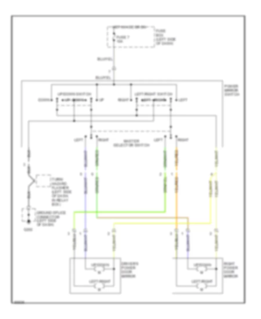
Power Mirror Wiring Diagram for Hyundai Scoupe 1995
List of elements for Power Mirror Wiring Diagram for Hyundai Scoupe 1995:
- Down
- Driver's power door mirror
- Fuse 7 10a
- Fuse box (left side of dash)
- G202
- Ground splice connector (left side of dash)
- Hot in acc or on
- Left
- Left/right
- Left/right switch
- Master selector switch
- Power mirror switch
- Right
- Right power door mirror
- Turn/ hazard flasher (left side of dash, in relay box)
- Up/down
- Up/down switch
POWER WINDOWS
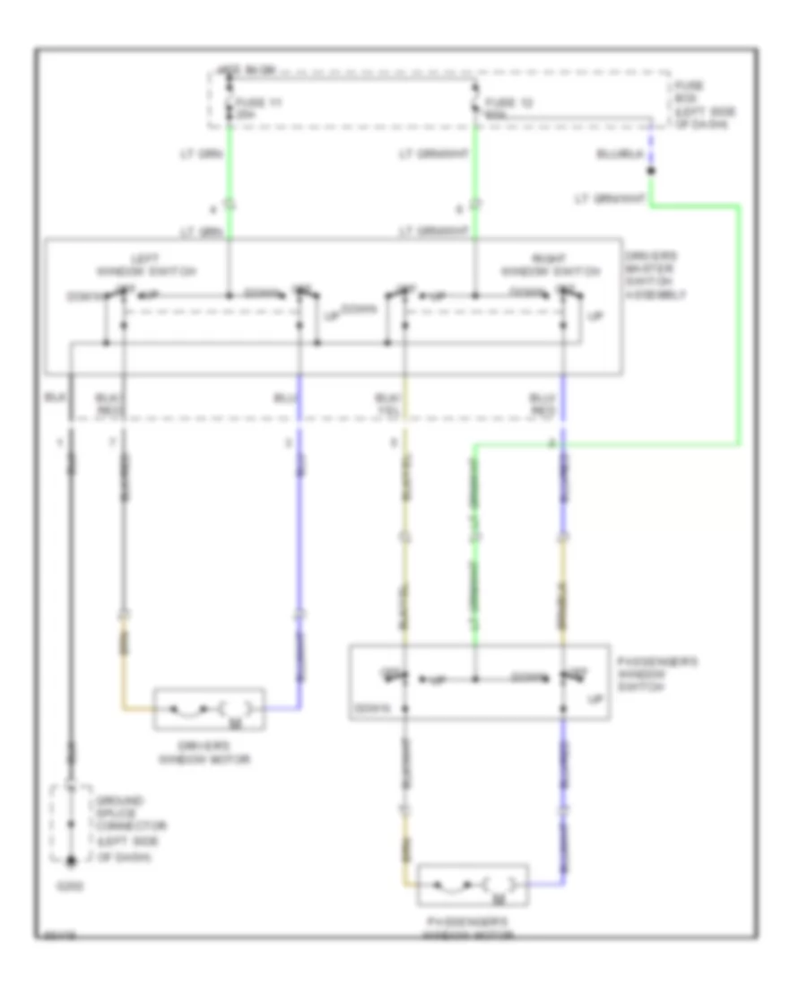
Power Window Wiring Diagram for Hyundai Scoupe 1995
List of elements for Power Window Wiring Diagram for Hyundai Scoupe 1995:
- (left side
- Down
- Driver's master switch assembly
- Driver's window motor
- Fuse 11 20a
- Fuse 12 20a
- Fuse box (left side of dash)
- G202
- Ground splice connector
- Hot in on
- Left window switch
- Of dash)
- Off
- Off down
- Passenger's window motor
- Passenger's window switch
- Right window switch
RADIO
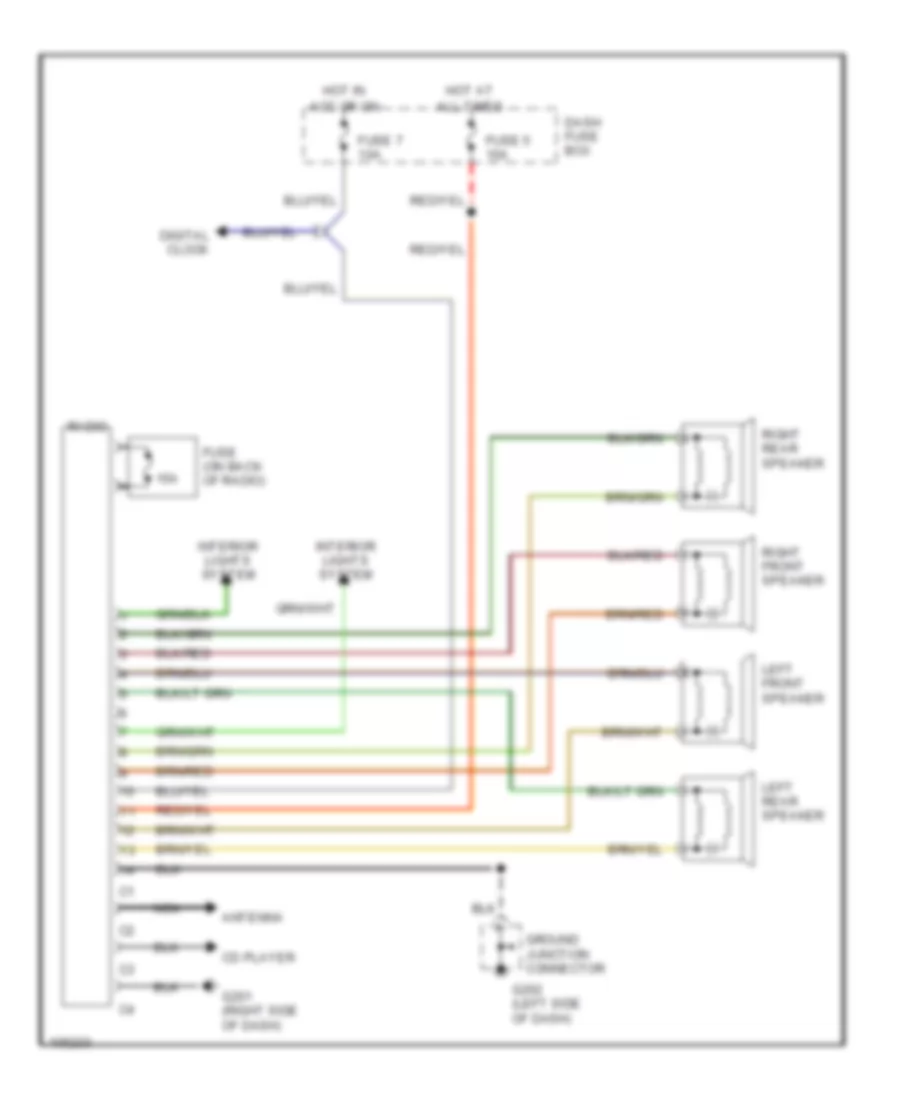
Radio Wiring Diagrams for Hyundai Scoupe 1995
List of elements for Radio Wiring Diagrams for Hyundai Scoupe 1995:
- 15a
- Acc or on
- All times
- Antenna
- Cd player
- Dash fuse box
- Digital clock
- Fuse (on back of radio)
- Fuse 5 10a
- Fuse 7 10a
- G201 (right side of dash)
- G202 (left side of dash)
- Ground junction connector
- Hot at
- Hot in
- Interior lights system
- Left front speaker
- Left rear speaker
- Nca
- Radio
- Right front speaker
- Right rear speaker
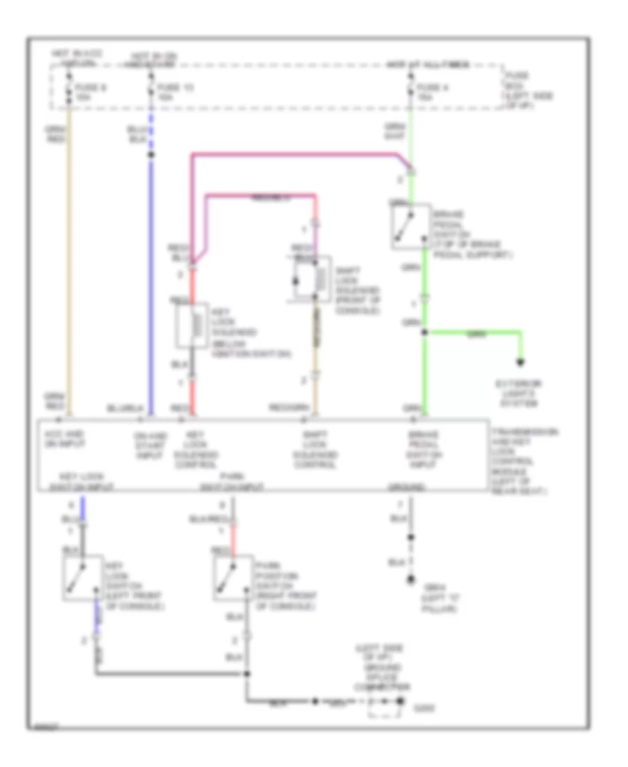
SHIFT INTERLOCKS
Shift Interlock Wiring Diagram for Hyundai Scoupe 1995
List of elements for Shift Interlock Wiring Diagram for Hyundai Scoupe 1995:
- (below ignition switch)
- (left "c" pillar)
- (left side
- Acc and on input
- Brake pedal switch (top of brake pedal support)
- Brake pedal switch input
- Exterior lights system
- Fuse 13 10a
- Fuse 4 15a
- Fuse 8 15a
- Fuse box (left side of i/p)
- G202
- G904
- Ground
- Ground splice connector
- Hot at all times
- Hot in acc and on
- Hot in on and start
- Key lock solenoid
- Key lock solenoid control
- Key lock switch (left front of console)
- Key lock switch input
- Of i/p)
- On and start input
- Park position switch (right front of console)
- Park switch input
- Red
- Shift lock solenoid (front of console)
- Shift lock solenoid control
- Transmission and key lock control module (left of rear seat)
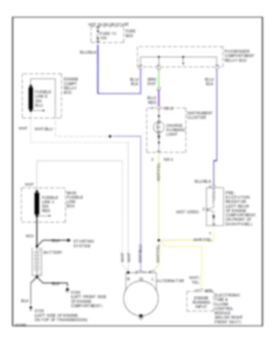
STARTING/CHARGING
Charging Wiring Diagram for Hyundai Scoupe 1995
List of elements for Charging Wiring Diagram for Hyundai Scoupe 1995:
- (not used)
- 105-2
- 105-3
- Alternator
- Battery
- Charge warning light
- Electronic time & alarm control module (below right front seat)
- Engine compt relay box
- Engine running input
- Fuse 13 10a
- Fuse box
- Fusible link a 50a red
- G100 (left front side of engine compartment)
- G130 (left side of engine, on top of transmission)
- Hot in on or start
- Instrument cluster
- M55
- Main fusible link box
- Nca
- Passenger compartment relay box
- Pre- excitation resistor (left rear of engine compartment, on front of dash panel)
- Starting system
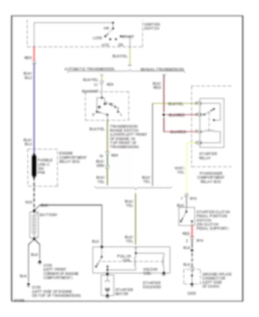
Starting Wiring Diagram for Hyundai Scoupe 1995
List of elements for Starting Wiring Diagram for Hyundai Scoupe 1995:
- Acc
- Automatic transmission
- Battery
- Engine compartment relay box
- Fusible link c 30a pnk
- G100 (left front corner of engine compartment)
- G130 (left side of engine, on top of transmission)
- G202
- Ground splice connector (left side of dash)
- Hold-in coil
- Ignition switch
- Lock
- M14
- M24
- Manual transmission
- N d
- Nca
- Passenger compartment relay box
- Pull-in coil
- Red
- Start
- Starter clutch pedal position switch (on clutch pedal support)
- Starter motor
- Starter relay
- Starter solenoid
- Transmission range switch (lower left front of engine, in top front of transmission)
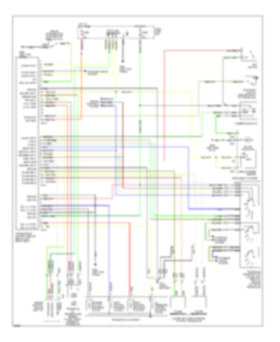
TRANSMISSION
Transmission Wiring Diagram for Hyundai Scoupe 1995
List of elements for Transmission Wiring Diagram for Hyundai Scoupe 1995:
- (above accelerator) accelerator pedal switch
- (lower left front of engine, on top of transaxle)
- (lower left side of engine, in top of transaxle)
- 2 input
- A/c sw input
- Accl sw input
- Air conditioning system
- Battery
- C01
- Damper clutch solenoid valve
- Dash fuse box
- Data link connector
- Diag output
- Drive input
- Econ mode
- Ect switch
- Eng rpm input
- Engine control module (left i/p)
- Engine controls system
- Exterior lights system
- Fuse 10a
- G111 (near battery)
- G200 (left kick panel)
- G202 (left side of i/p)
- Ground
- Hi oil temp
- High temp
- Hot at all times
- Hot in on
- I05-1
- I05-3
- I06
- Ignition
- Instrument cluster
- Kick down switch (center front of transaxle)
- Kickdn sw
- L input
- Lo oil temp
- Low temp
- M02
- M07-1
- M07-2
- M07-3
- N/a
- Nca
- Neutral input
- O/d off
- O/d off indicator
- O/d on
- O/d sw input
- Oil pressure control solenoid valve
- Overdrive switch
- Park input
- Pulse gen a
- Pulse gen b
- Pulse generator a
- Pulse generator b
- Red
- Reverse input
- Rsw
- Sensor gnd
- Shift control solenoid valve a
- Shift control solenoid valve b
- Signal eng speed
- Sol vlv ctrl
- Starting/ charging system
- Tps input
- Tps output
- Transaxle oil temperature sensor (in left front corner of transaxle)
- Transaxle range switch
- Transaxle valve body
- Transmission control module (below left front seat)
- Veh spd input
- Vehicle speed sensor
TRUNK, TAILGATE, FUEL DOOR
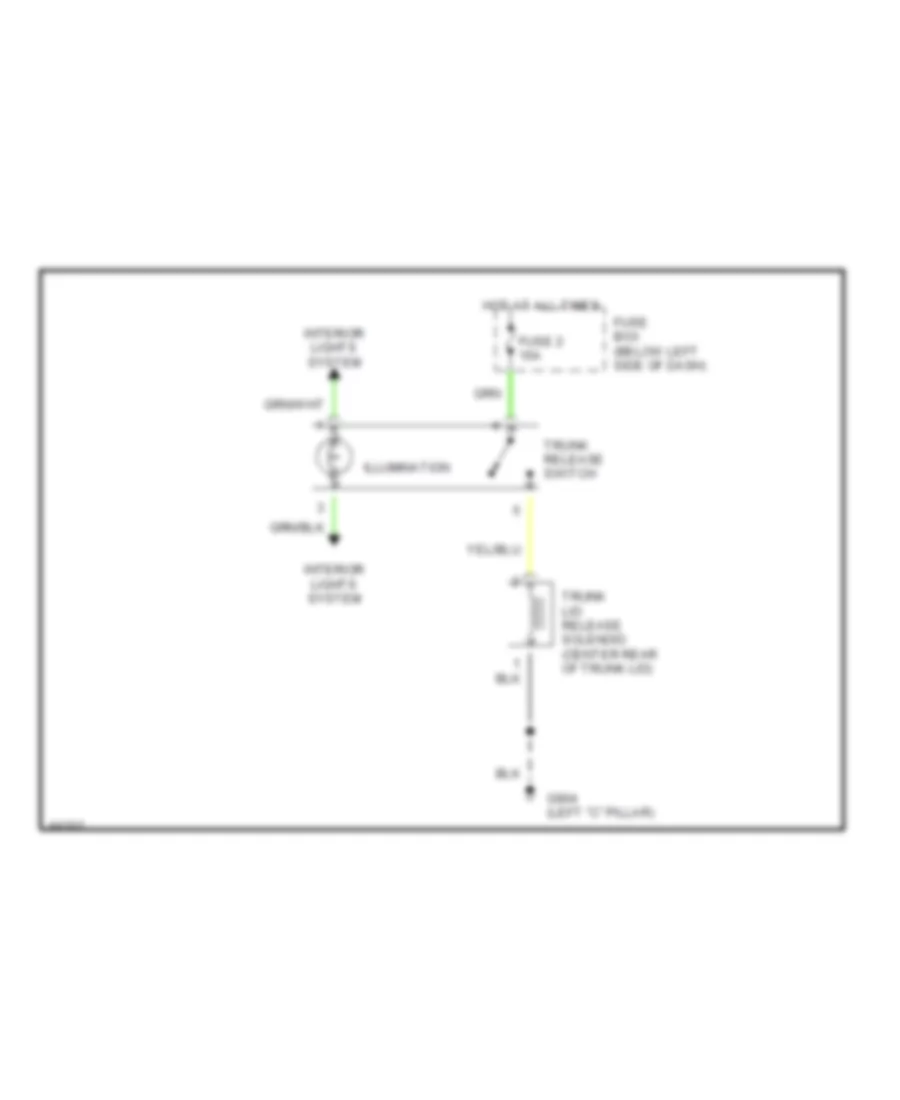
Trunk Release Wiring Diagram for Hyundai Scoupe 1995
List of elements for Trunk Release Wiring Diagram for Hyundai Scoupe 1995:
- Fuse 2 15a
- Fuse box (below left side of dash)
- G904 (left "c" pillar)
- Hot at all times
- Illumination
- Interior lights system
- Trunk lid release solenoid (center rear of trunk lid)
- Trunk release switch
WARNING SYSTEMS
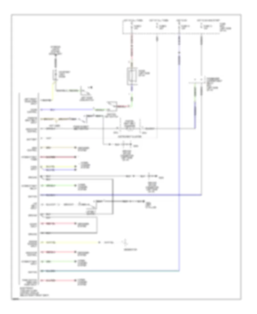
Warning System Wiring Diagrams for Hyundai Scoupe 1995
List of elements for Warning System Wiring Diagrams for Hyundai Scoupe 1995:
- (left "c" pillar)
- (left side
- Battery
- Chime (left side of i/p)
- Chime control
- Courtesy light diode
- Defogger system
- Electronic time and alarm control module (below right front seat)
- Engine running input
- Fasten seat belt indicator
- Fuse 10 15a
- Fuse 13 10a
- Fuse 5 10a
- Fuse 6 20a
- Fuse box (left side of i/p)
- G202
- G904
- Generator
- Grid control
- Ground
- Ground splice connector
- Hot at all times
- Hot in on
- Hot in on and start
- I05-2
- Ignition
- Ignition key switch
- Indicator control
- Instrument cluster
- Interior lights system (dome light)
- Intermittent input
- Intermittent relay
- Intermittent timer
- Lap belt input
- Lap belt switch
- Left door jamb switch
- Left front door open input
- Nca
- Not used
- Of i/p)
- On/off input
- Park switch feed and park input
- Passenger compartment relay box (left side of i/p)
- Passive seat belt input
- Passive seat belt switch
- Wash input
- Wiper/ washer system
WIPER/WASHER
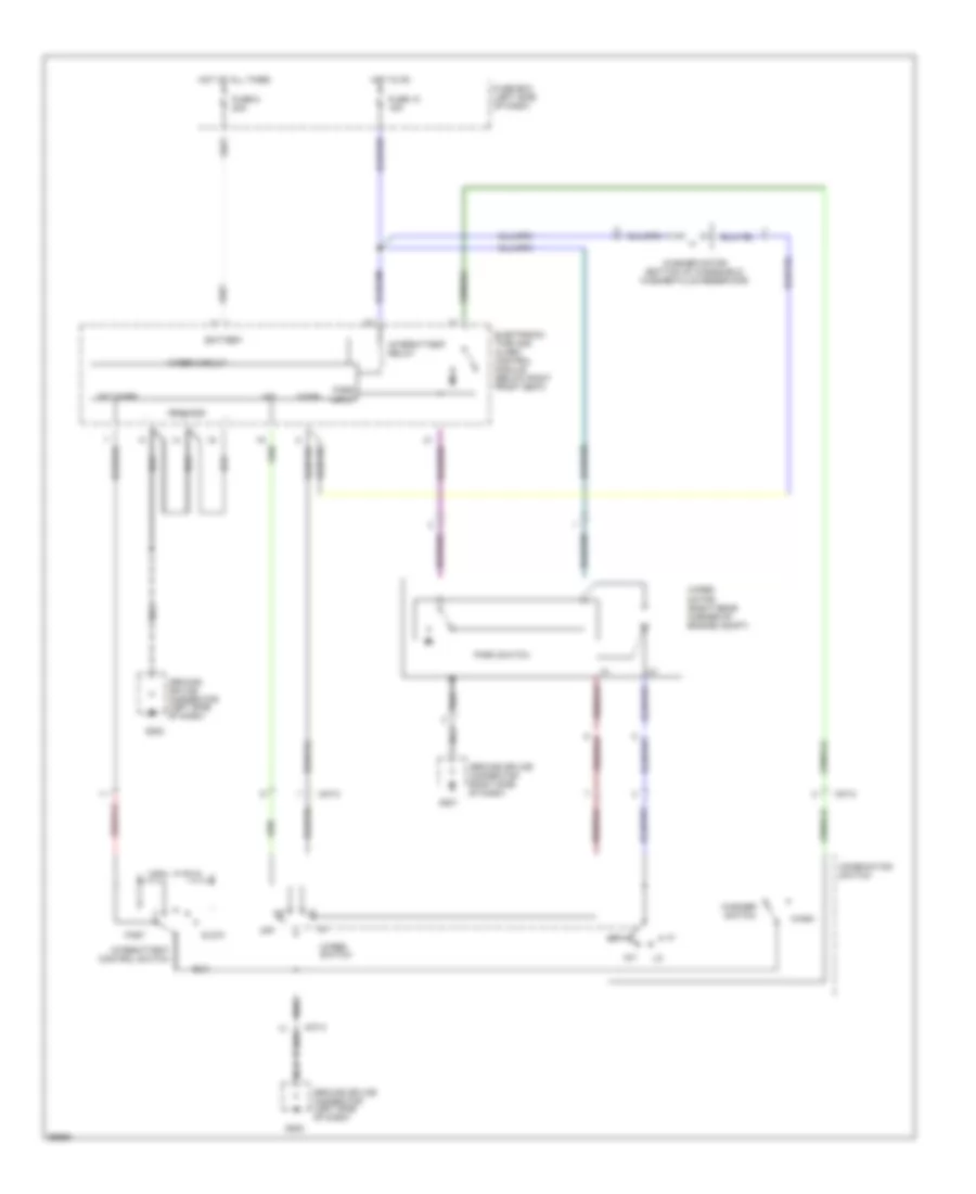
Wiper/Washer Wiring Diagram for Hyundai Scoupe 1995
List of elements for Wiper/Washer Wiring Diagram for Hyundai Scoupe 1995:
- Battery
- Combination switch
- Electronic time and alarm control module (below right front seat)
- Fast
- Fuse 10 15a
- Fuse 6 20a
- Fuse box (left side of dash)
- G201
- G202
- Ground splice connector (left side of dash)
- Ground splice connector (right side of dash)
- Grounds
- Hot at all times
- Hot in on
- Int
- Int
- Int timer
- Intermittent control switch
- Intermittent relay
- M37-2
- Off
- Park input
- Park switch
- Slow
- Wash
- Washer motor (bottom of windshield washer fluid reservoir)
- Washer switch
- Wiper circuit
- Wiper motor (right rear corner of engine compt)
- Wiper switch

 Čeština
 Dansk
Dansk Deutsch
 Ελληνικά
 English
 English
 Español
 Suomi
Suomi Français
 Français
 עברית
עברית Hrvatski
 Magyar
 Italiano
 日本語
日本語 한국어
한국어 Nederlands
 Polski
 Português
 Română
 Русский
 Slovenčina
 Slovenščina
 Svenska
 Türkçe
 中文 (中国)