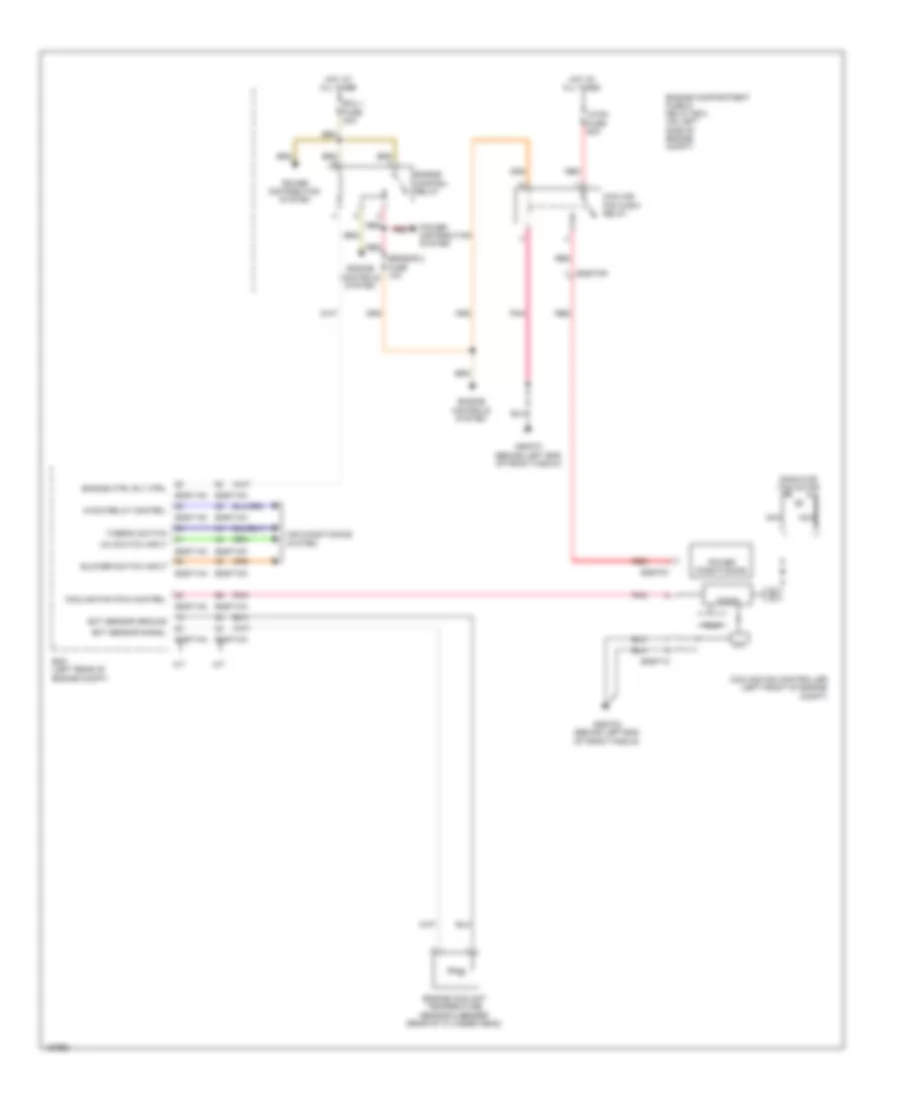
AIR CONDITIONING
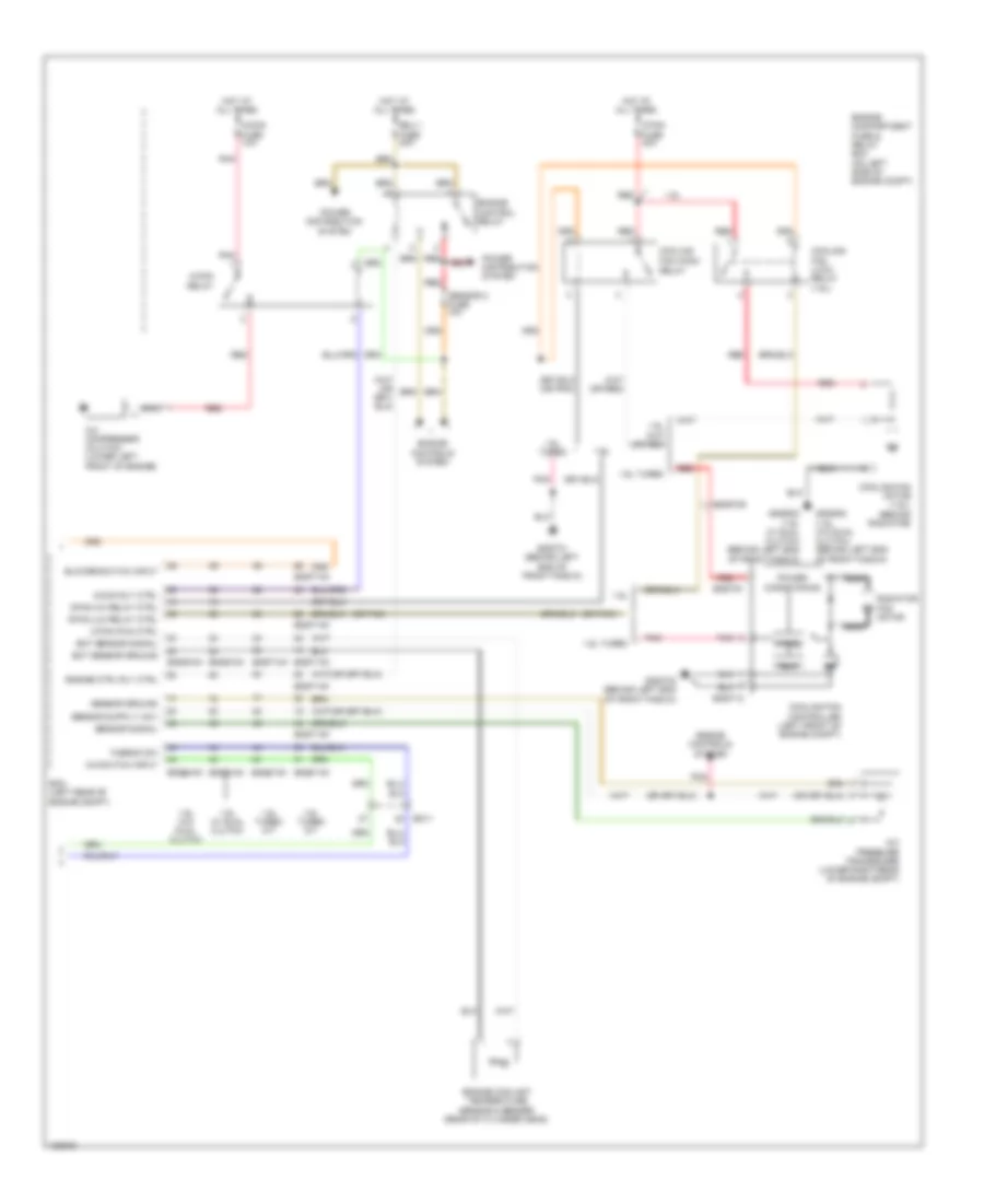
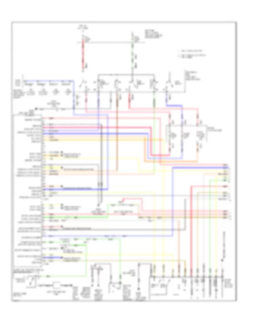
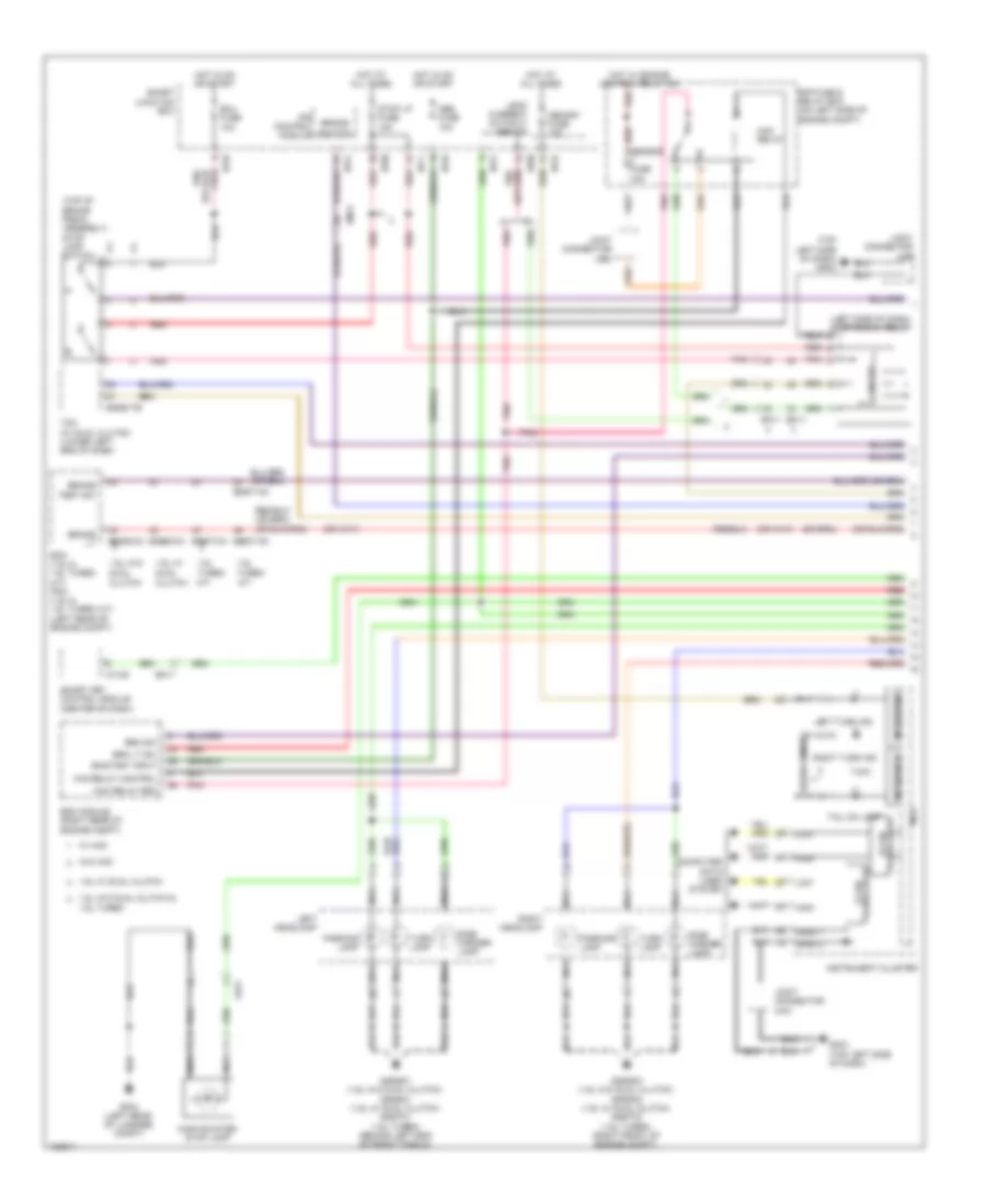
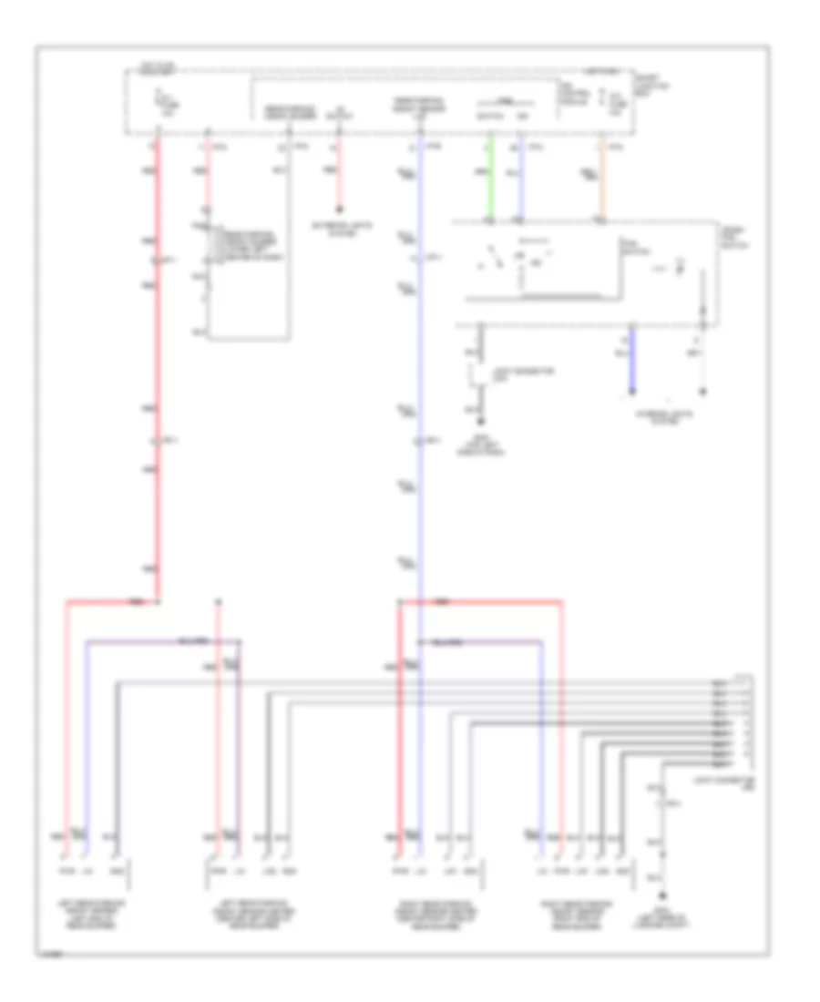
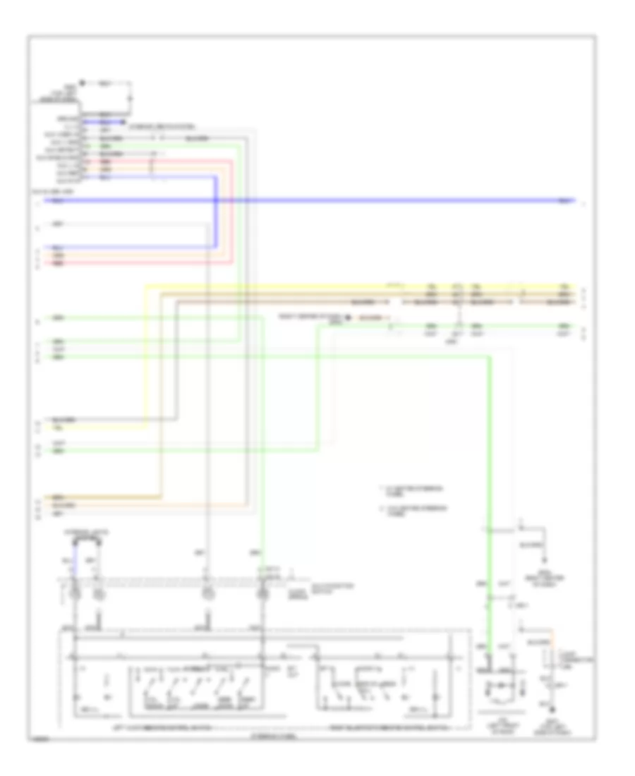
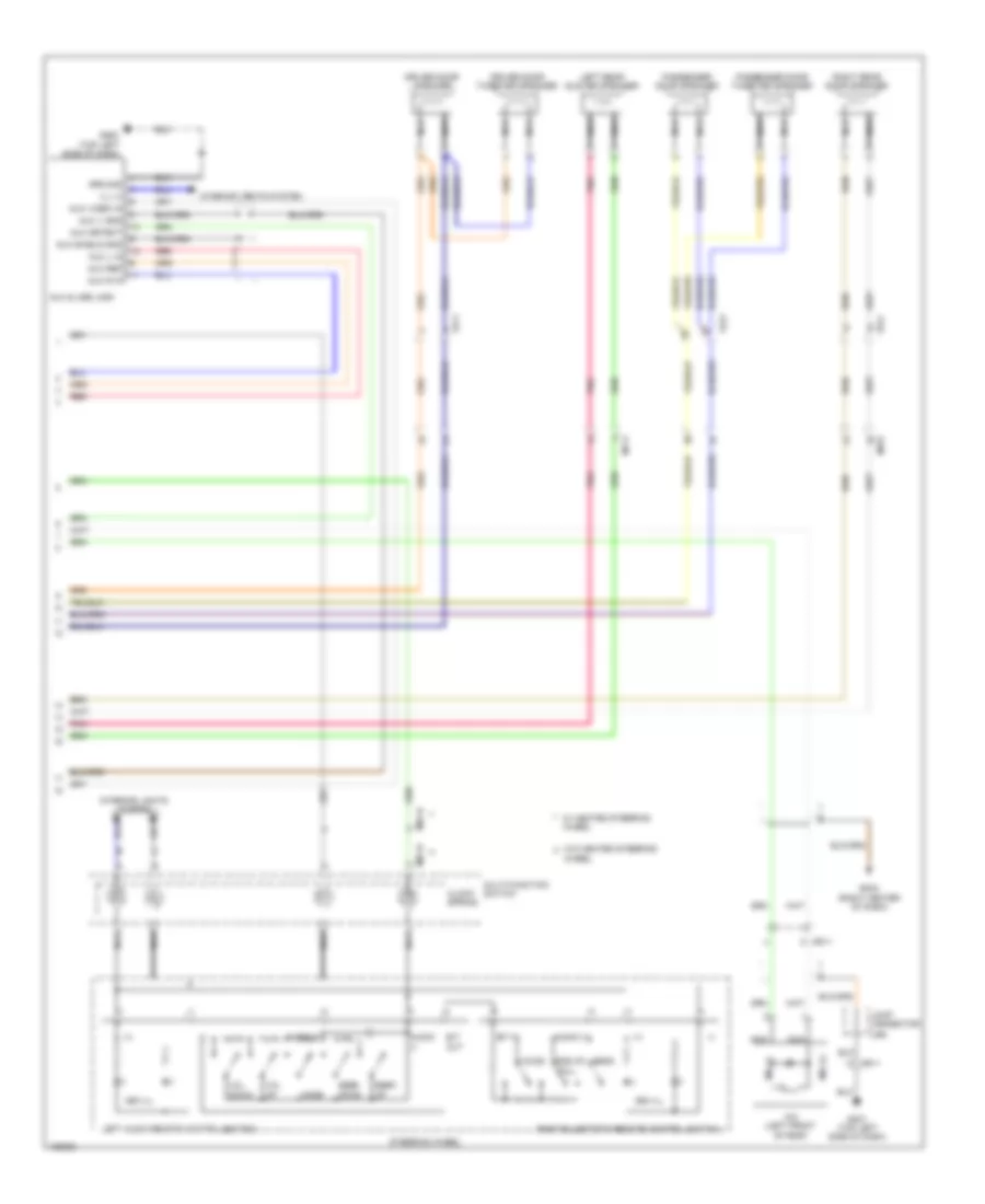
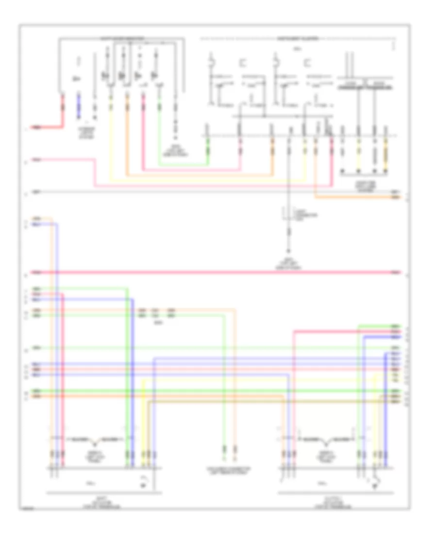
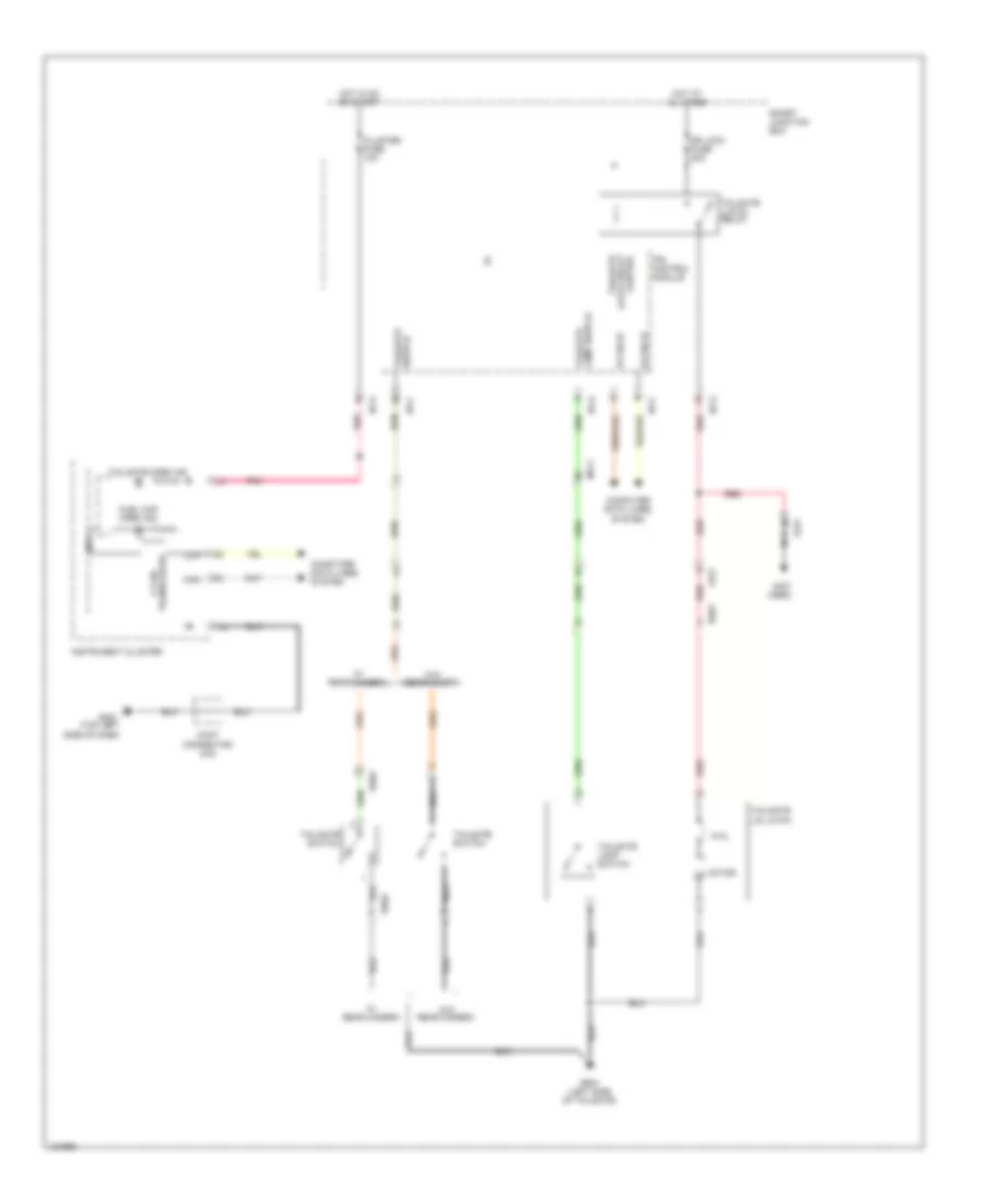
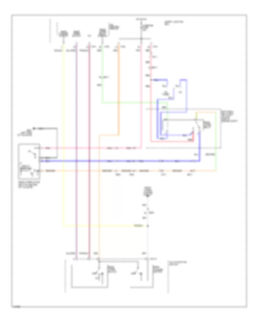
Manual A/C Wiring Diagram (1 of 2) for Hyundai Veloster Turbo 2014
 https://portal-diagnostov.com/license.html
Automotive Electricians Portal FZCO
Automotive Electricians Portal FZCO
https://portal-diagnostov.com/license.html
https://portal-diagnostov.com/license.html
Automotive Electricians Portal FZCO
Automotive Electricians Portal FZCO
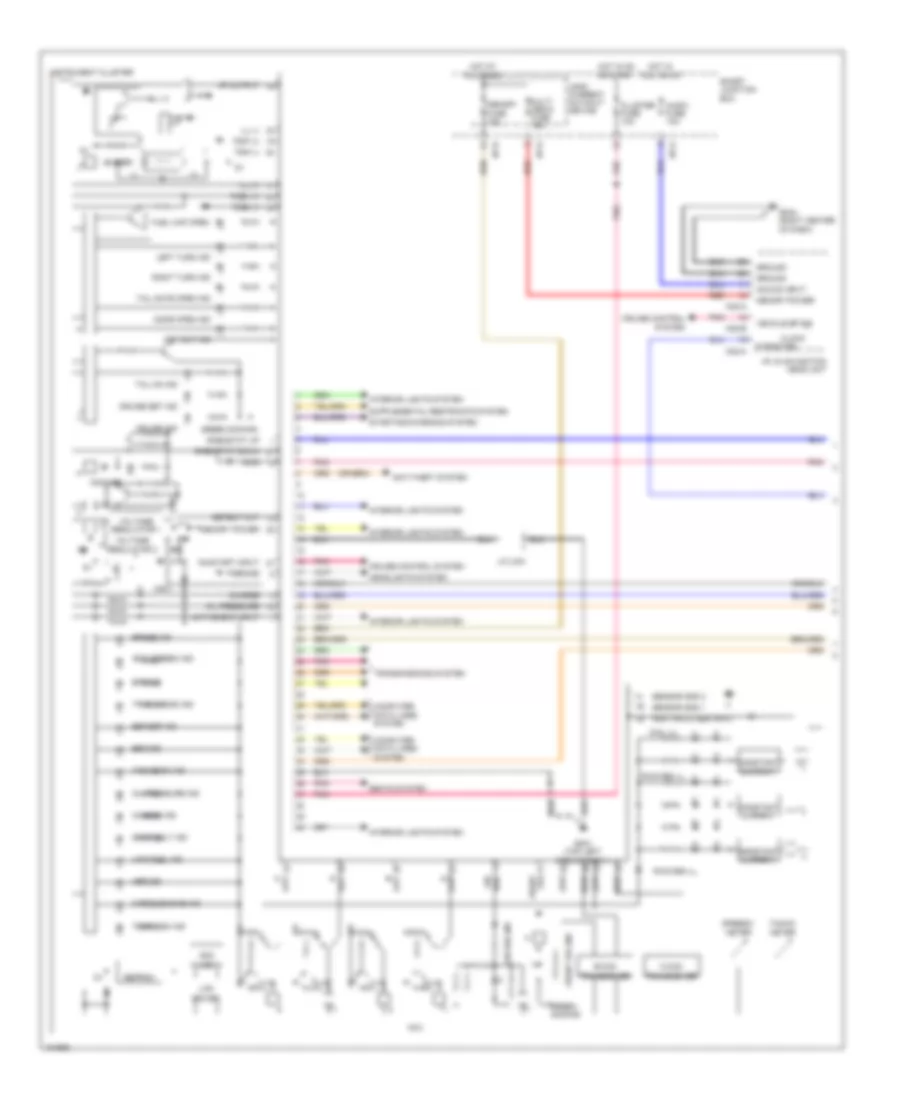
List of elements for Manual A/C Wiring Diagram (1 of 2) for Hyundai Veloster Turbo 2014:
- (near blower motor) blower resistor
- (under right side of dash) blower motor
- A/c control module (under center console)
- A/c switch
- A/con fuse 10a
- Blower feed back
- Blower fuse 40a
- Blower motor
- Blower relay
- Blower switch
- Cruise control system
- Defogger switch
- Detent out (+)
- Em61
- Engine compartment fuse & relay box (on left side of engine compt)
- Evaporator sensor
- Evaporator sensor (lower left side of hvac evaporator assembly)
- Gggg02 (1.6l w/o dual clutch) (behind left end of front fascia)
- Gggt01 (1.6l turbo) gggd02 (1.6l w/ dual clutch) (behind left end of front fascia)
- Gm01 (top left side of dash)
- Gm06 (lower left center of dash)
- Ground
- Hazard switch
- High
- Hot at all times
- Hot in on
- Hot w/ rear defogger relay energized
- Htd mirr fuse 10a
- Ig 2 fuse 10a
- Iii
- Iiii
- Ill (+)
- Ill (-)
- Intake actuator (top left side of hvac blower housing)
- Intake actuator f/b
- Intake actuator fre
- Intake actuator rec
- Interior lights system
- Ip-c
- Ip-f
- Ip-g
- Ip-h
- Ip-n
- Ips control module
- J/c jm02 (lower right center of dash)
- Leak current autocut device
- Low
- M/high
- M/low
- M21-a
- M21-b
- Memory fuse 10a
- Memory power
- Mode actuator (left side of hvac unit)
- Mode actuator def
- Mode actuator f/b
- Mode actuator vent
- Multi fuse
- Off
- On input
- Pnk
- Red
- Rr defogger rly "on" in
- Sensor (+5v)
- Sensor ground
- Smart junction box
- Temp actuator cool
- Temp actuator f/b
- Temp actuator warm
- Temperature actuator (lower right side of hvac unit)
- Thermo switch
- Vehicle speed
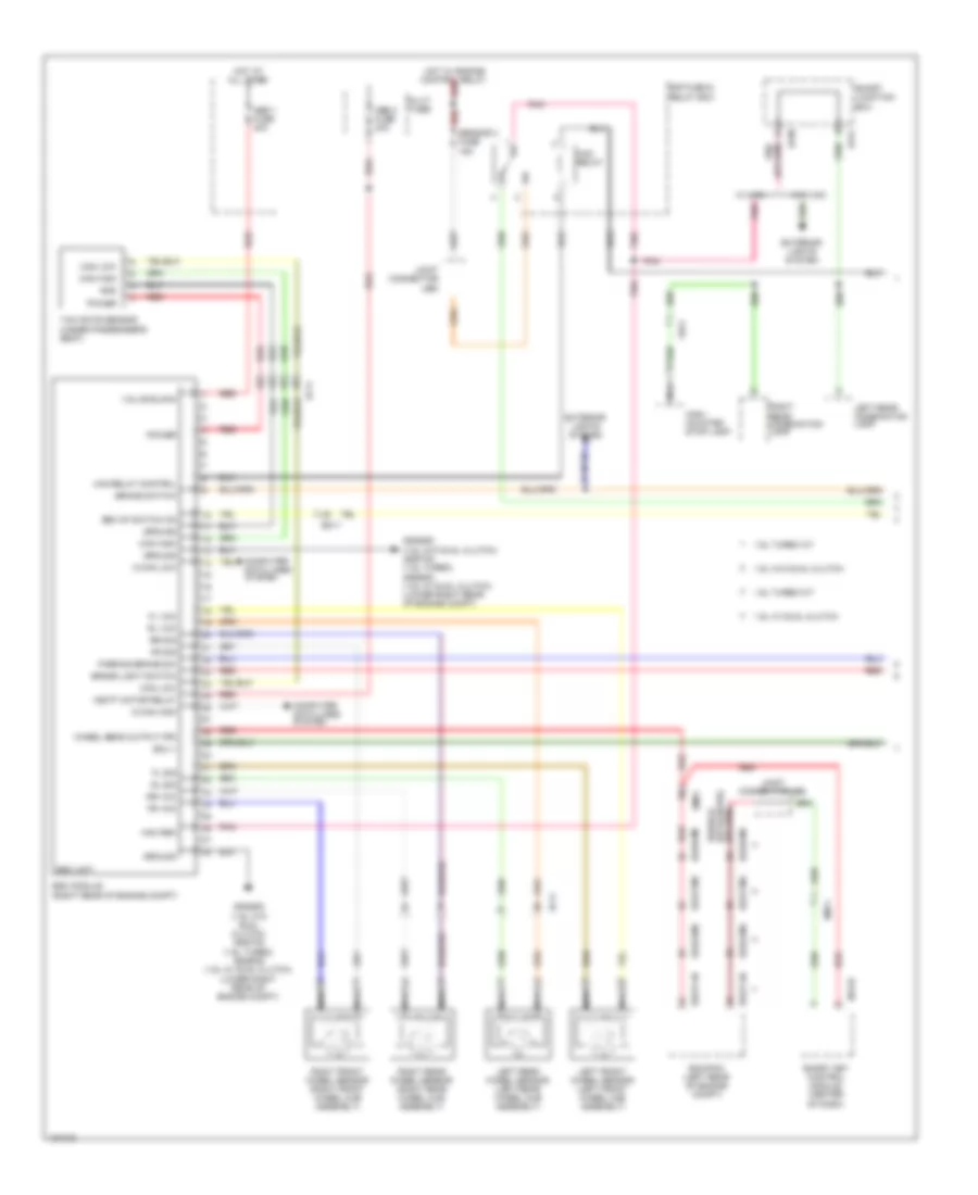
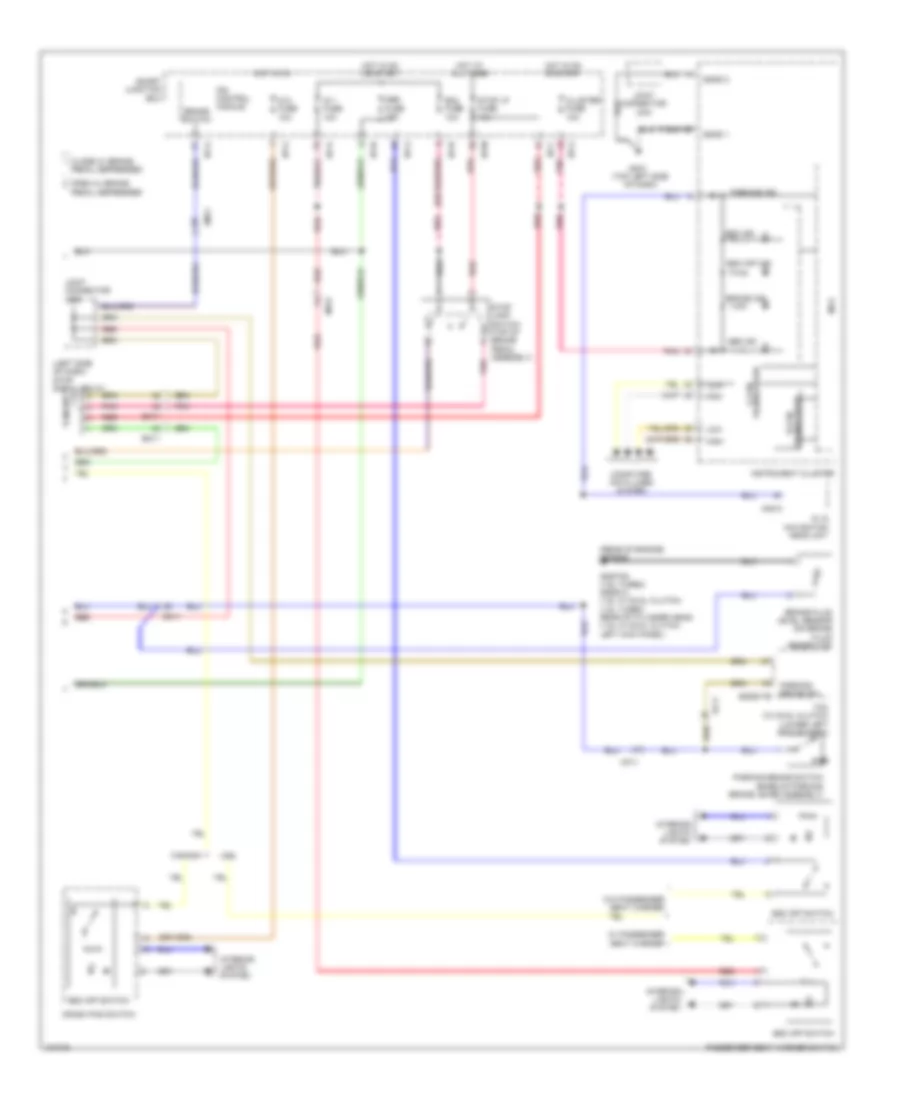
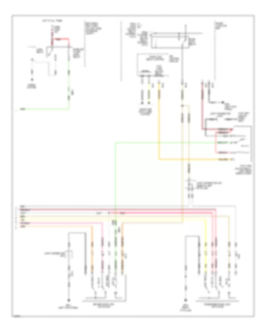
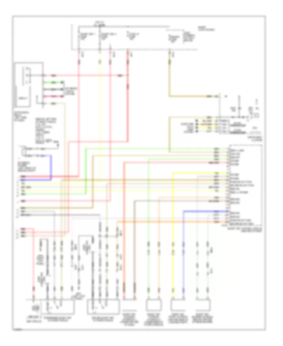
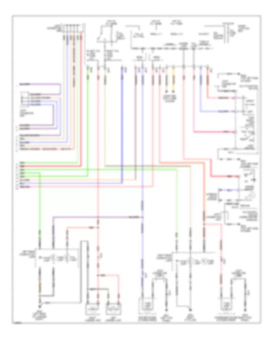
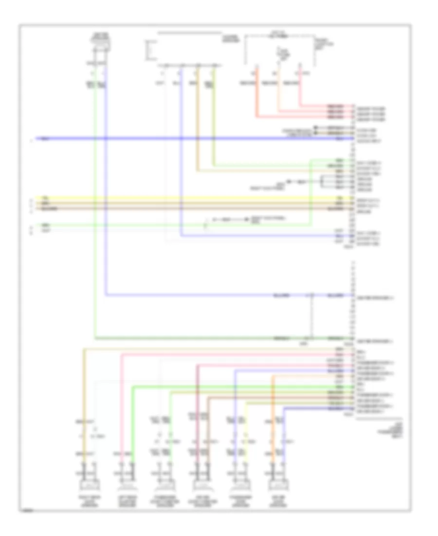
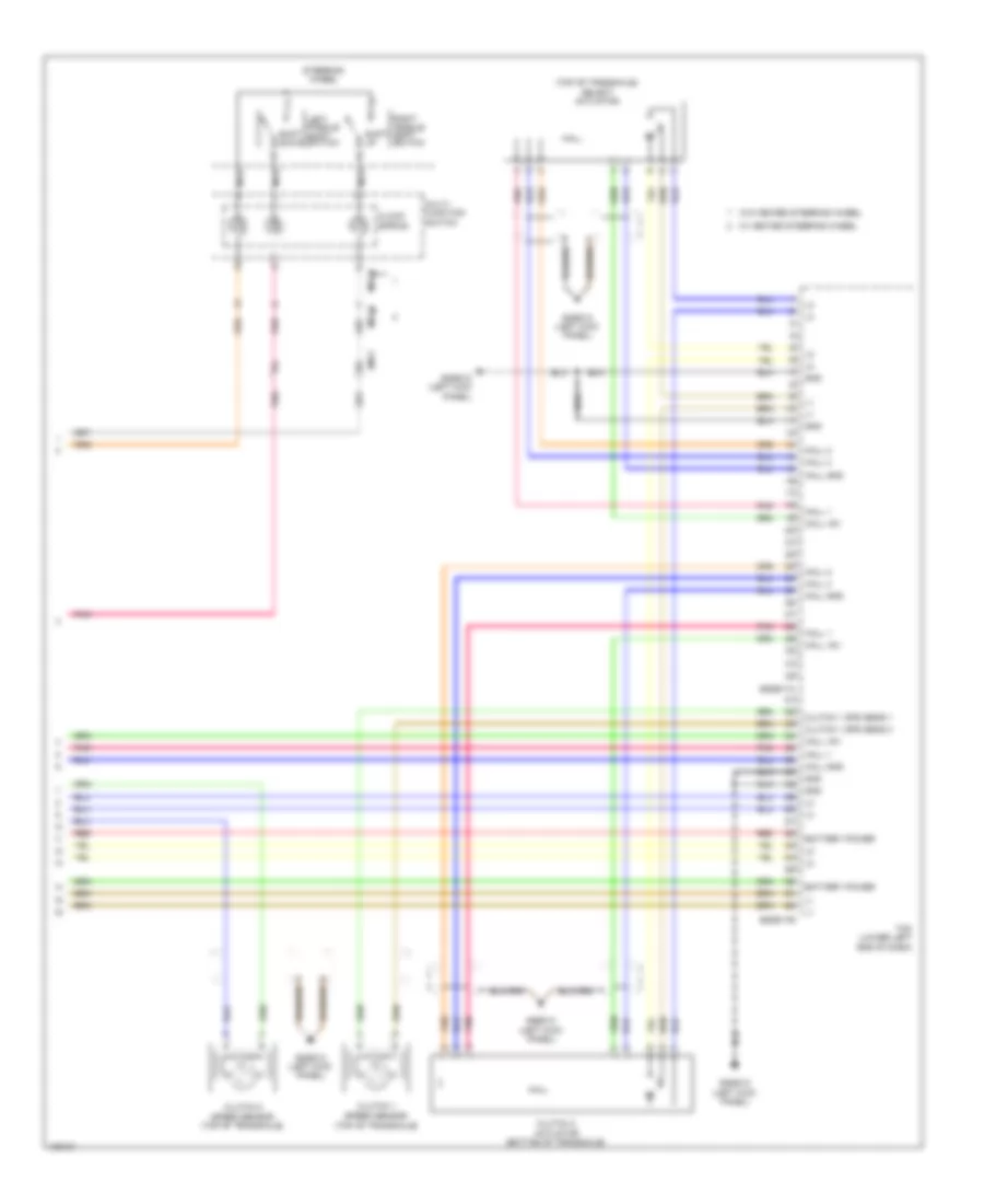
Manual A/C Wiring Diagram (2 of 2) for Hyundai Veloster Turbo 2014
List of elements for Manual A/C Wiring Diagram (2 of 2) for Hyundai Veloster Turbo 2014:
- (or pnk)
- 1.6l
- 1.6l turbo
- 1.6l turbo a/t
- 1.6l turbo m/t
- 1.6l w/ dual clutch
- 1.6l w/o dual clutch
- A/c compressor (clutch) (lower left front of engine)
- A/c pressure transducer (lower right rear of engine compt)
- A/c switch input
- A/con
- A/con fuse 10a
- A/con rly ctrl
- Blower switch input
- C/fan (hi) relay ctrl
- C/fan (lo) relay ctrl
- C/fan fuse 40a
- C/fan pwm ctrl
- Control relay
- Cooling
- Cooling fan (low) relay (1.6l)
- Cooling fan controller (left front of engine compt)
- Cooling fan motor (1.6l) (behind radiator)
- Ecm (left rear of engine compt)
- Ect sensor ground
- Ect sensor signal
- Ecu 1 fuse 30a
- Eggd-ma
- Eggd-mk
- Eggg-ma
- Eggg-mk
- Eggt-aa
- Eggt-ak
- Eggt-ma
- Eggt-mk
- Eggt12
- Eggt91
- Eggtcr
- Em11
- Engine
- Engine compartment fuse & relay box (on left side of engine compt)
- Engine controls system
- Engine coolant temperature sensor & sender (rear of cylinder head)
- Engine ctrl rly ctrl
- Fan (high) relay
- Gggd02 (1.6l w/ dual clutch) (behind left end of front fascia)
- Gggg02 (1.6l w/o dual clutch) (behind left end of front fascia)
- Gggt01 (behind left end of front fascia)
- Gggt02 (behind left end of front fascia)
- Hot at all times
- Micom
- Nca
- Pnk
- Power conditioning
- Power distribution system
- Radiator fan motor
- Red
- Relay
- Sensor 2 fuse 10a
- Sensor ground
- Sensor signal
- Temp
- Thermo sw
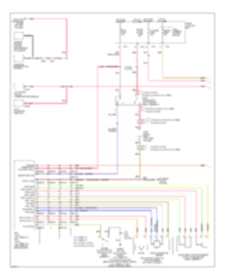
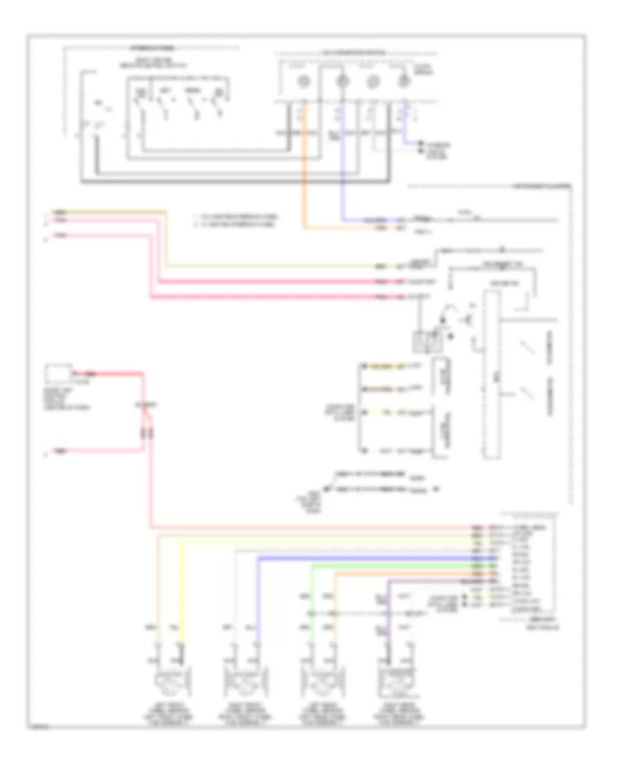
ANTI-LOCK BRAKES
Anti-lock Brakes Wiring Diagram (1 of 2) for Hyundai Veloster Turbo 2014
List of elements for Anti-lock Brakes Wiring Diagram (1 of 2) for Hyundai Veloster Turbo 2014:
- 1.6l turbo a/t
- 1.6l turbo m/t
- 1.6l w/ dual clutch
- 1.6l w/o dual clutch
- Abs 1 fuse 40a
- Abs 2 fuse 30a
- Box
- Brake light switch
- Brake switch
- C-can high
- C-can low
- Can high
- Can low
- Computer data lines system
- E/r fuse & relay box
- Ecm/pcm (left rear of engine compt)
- Ecu +
- Ef11
- Eggd-ma
- Eggd-mk
- Eggg-ma
- Eggg-mk
- Eggt-ak
- Eggt-ma
- Eggt-mk
- Em11
- Em61
- Esc module (right rear of engine compt)
- Esc of switch on
- Esc unit
- Exterior lights system
- Fl sig
- Fl vcc
- Fr sig
- Fr vcc
- Fr21
- Gggg08 (1.6l w/o dual clutch) gggt08 (1.6l turbo) gggd08 (1.6l w/ dual clutch) (lower right rear of engine compt)
- Gnd
- Ground
- Hac relay
- Hac relay control
- Hac rsm
- High- mounted stop lamp
- Hot at all times
- Hot w/ engine control relay
- I/p-k
- I/p-m
- Joint connector ueb
- Joint connector ued
- Left front wheel sensor (left front wheel hub assembly)
- Left rear combination lamp
- Left rear wheel sensor (left rear wheel hub assembly)
- M13-b
- Multi fuse
- Nca
- Parking brake sw
- Pnk
- Power
- Red
- Right front wheel sensor (right front wheel hub assembly)
- Right rear combination lamp
- Right rear wheel sensor (right rear wheel hub assembly)
- Rl sig
- Rl vcc
- Rr sig
- Rr vcc
- Sensor 3 fuse 15a
- Smart junction
- Smart key control module (center of dash)
- Valve block
- Vbatt motor relay
- W/ hac
- W/o hac
- Wheel sens output (fr)
- Yaw rate sensor (under passenger's seat)
Anti-lock Brakes Wiring Diagram (2 of 2) for Hyundai Veloster Turbo 2014
List of elements for Anti-lock Brakes Wiring Diagram (2 of 2) for Hyundai Veloster Turbo 2014:
- (left side of dash) stop signal relay
- (rear of engine) gggg09
- (top left side of dash)
- Abs fuse 10a
- Abs ind
- Av & navigation head unit
- Brake fluid level sensor (on brake fluid reservoir)
- Brake ind
- Brake switch
- Canada
- Circuit
- Close w/ brake
- Cluster fuse 10a
- Computer data lines system
- Crash pad switch
- Ecu fuse 10a
- Ef11
- Eggd-tb
- Em11
- Esc ind
- Esc off ind
- Esc off switch
- Gggt09 (1.6l turbo) gggd13 (1.6l w/ dual clutch) (1.6l turbo: rear of cylinder head) (1.6l w/ dual clutch: left kick panel)
- Gm01
- High
- Hot at all times
- Hot in on
- Hot in on or start
- I/p-a
- I/p-f
- I/p-g
- I/p-k
- I/p-m
- I/p-n
- Ig 1 fuse 10a
- Ig 2 fuse 10a
- Instrument cluster
- Interior lights system
- Ips control module
- Joint connector ueb
- Joint connector uma
- Low
- M02-a
- Mcu
- Mf11
- Mf61
- Open w/ brake
- P/brake ind
- Parking brake sw
- Parking brake switch (base of parking brake lever assembly)
- Passenger seat warmer switch
- Pedal depressed
- Pnk
- Red
- Sgnd 1
- Sgnd 2
- Smart junction box
- Stop lamp switch (top of brake pedal assembly)
- Stop lp fuse 15a
- Tcm (w/ dual clutch) (lower left end of dash)
- Transceiver b-can
- Transceiver c-can
- Usa
- W/ passenger seat warmer
- W/o passenger seat warmer
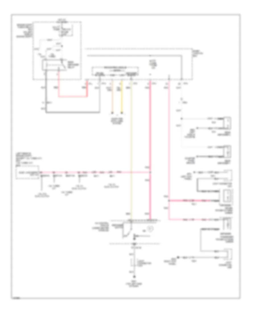
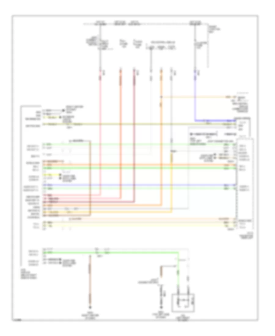
ANTI-THEFT
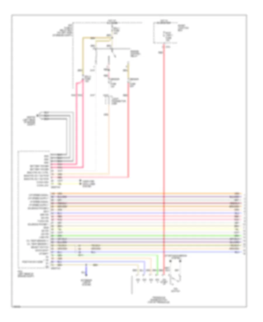
Forced Entry Wiring Diagram (1 of 2) for Hyundai Veloster Turbo 2014
List of elements for Forced Entry Wiring Diagram (1 of 2) for Hyundai Veloster Turbo 2014:
- (left kick panel) gf01
- (right kick panel) gf02
- Burglar alarm horn relay control
- Burglar alarm relay control
- Door lock
- Door lock switch
- Door unlock
- Door unlock relay
- Door unlock relay control
- Dr lk
- Dr lock fuse 20a
- Dr unlk
- Driver door key unlock signal
- Driver door lock/ unlock signal
- Driver/ passenger door key lock signal
- Em61
- Fd11
- Fd21
- Fd41
- Flasher sound relay
- Flasher sound relay control
- Fr21
- Gf04 (right "c" pillar)
- Gggg04 (1.6l w/o dct) gggd04 (1.6l w/ dct) gggt04 (1.6l turbo) (right front of engine compt)
- Gr01 (left side of tailgate)
- Hood switch
- Hood switch (right front of engine compt)
- Hot at all times
- I/p-a
- I/p-b
- I/p-c
- I/p-k
- Ips control module
- Joint connector jf01 (base of left "b" pillar)
- Joint connector uda
- Joint connector udb
- Lock
- Mf11
- Mf61
- Nca
- Operation sound
- Passenger door key unlock signal
- Passenger door lock/ unlock signal
- Passenger power window switch
- Power window main switch
- Red
- Right rear door lock actuator
- Right rear door lock/ unlock signal
- Rr01
- Rr02
- Smart junction box
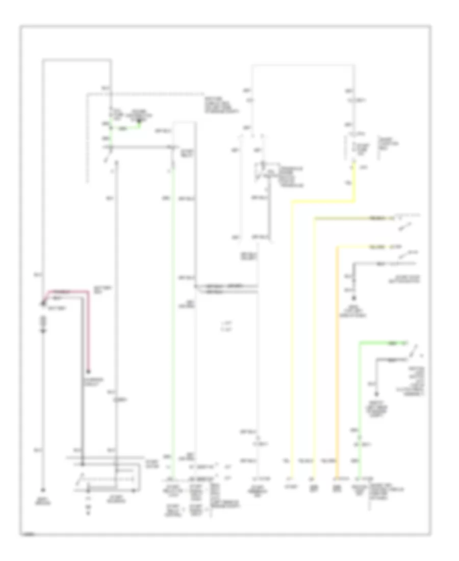
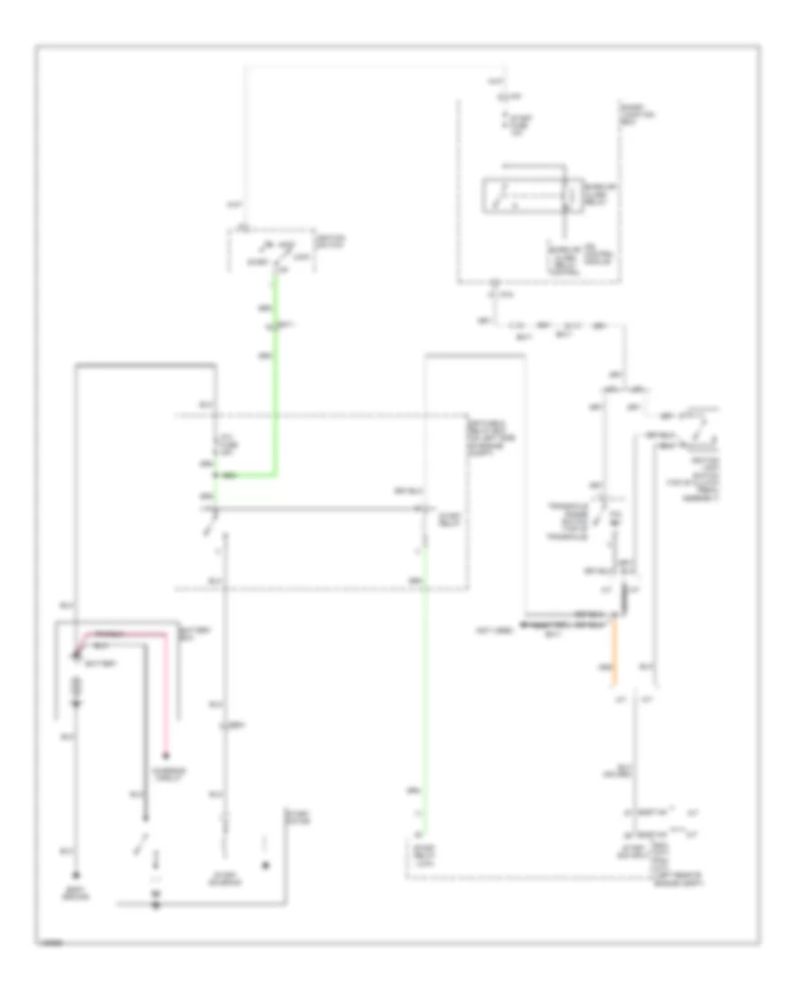
- Starting/ charging system
- Tail gate relay switch
- Tailgate switch
- To door lock relay (diagram 2 of 2)
- Unlock
- W/ rear camera
- W/o rear camera
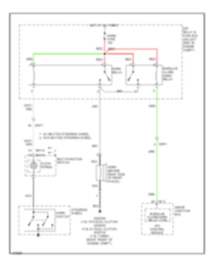
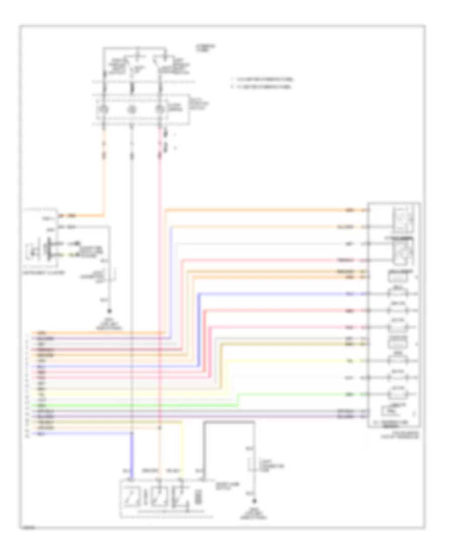
Forced Entry Wiring Diagram (2 of 2) for Hyundai Veloster Turbo 2014
List of elements for Forced Entry Wiring Diagram (2 of 2) for Hyundai Veloster Turbo 2014:
- (top left side of dash) gm01
- B-can
- Burglar alarm horn relay
- Computer data lines system
- Door lock relay
- Door lock relay control
- Dr lk
- Dr unlk
- Driver door lock actuator
- E/r fuse & relay box (on left side of engine compt)
- Em11
- Fd11
- Fd21
- From door a
- From flasher b
- Gf01 (left kick panel)
- Gf04 (right "c" pillar)
- High
- Horn fuse 15a
- Horn relay
- Horns system
- Hot at all times
- I/p-c
- I/p-d
- I/p-f
- I/p-k
- Ips control module
- Joint connector jf01 (base of left "b" pillar)
- Joint connector uda
- Joint connector uma
- Key lk
- Key unlk
- Low
- Mf61
- Passenger door lock actuator
- Pnk
- Red
- Smart junction box
- Sound relay (diagram 1 of 2)
- Two turn unlock relay (left rear side of dash)
- Two turn unlock relay control
- Unlock relay (diagram 1 of 2)
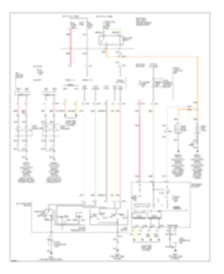
Immobilizer Wiring Diagram, with Smart Key System (1 of 2) for Hyundai Veloster Turbo 2014
List of elements for Immobilizer Wiring Diagram, with Smart Key System (1 of 2) for Hyundai Veloster Turbo 2014:
- 1.6l
- 1.6l turbo
- 1.6l turbo a/t
- 1.6l turbo m/t
- 1.6l w/ dual clutch
- 1.6l w/o dual clutch
- 1.6l w/o dual clutch & 1.6l turbo
- Acc relay
- Acc/on input
- Audio fuse 10a
- B-can high
- B-can low
- C-can high
- C-can low
- Computer data lines system
- Driver dr lk/unlk sw
- E/r fuse relay & box (on left side of engine compt)
- Ecm/pcm (left rear of engine compt)
- Ecu fuse 10a
- Eggd-mk
- Eggg-mk
- Eggt-ak
- Eggt-mk
- Em11
- Em61
- Ems com
- Engine controls system
- Engine rpm
- External buzzer
- Gggg02 (behind left end of front fascia)
- Gggt07 (left rear of engine compt)
- Gm02 (top left side of dash)
- Gm05 (left center of dash)
- Ground
- Hot at all times
- Htd strg fuse 15a
- I/p-e
- I/p-f
- I/p-g
- I/p-h
- Ig 1 fuse 40a
- Ig 2 fuse 40a
- Ig1 relay
- Ig2 relay
- Ignition lock switch
- Ignition lock switch (top of clutch pedal assembly)
- Ill
- Immo antenna ground
- Immo antenna power
- Immo data line
- Interior lights system
- Joint connector ueb
- Joint connector umb
- K-line
- M06-a
- M06-b
- M13-a
- M13-b
- Memory power
- On input
- On/start input
- P position switch
- P position switch/
- Pass dr lk/unlk sw
- Pdm relay box (top left side of dash)
- Pnk
- Red
- Smart junction box
- Smart key control module (center of dash)
- Sport mode switch
- Ssb acc
- Ssb ign
- Ssb ill ground
- Ssb ill power
- Ssb off
- Ssb sw1
- Ssb sw2
- Start feedback signal
- Start stop button switch
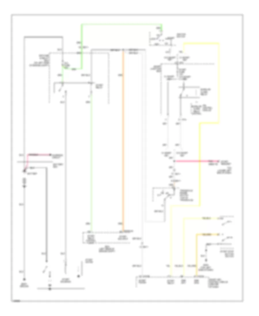
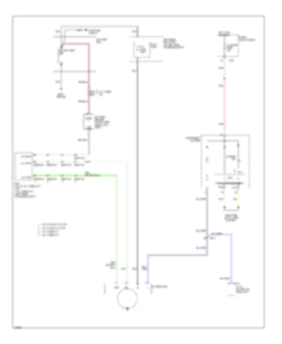
- Starting/ charging system
- Starting/charging system
- Stop lamp power
- Stop lamp signal
- Terminal ctrl acc rly
- Terminal ctrl ig1 rly
- Terminal ctrl ig2 rly
- Terminal ctrl st rly
- Vehicle speed input
- W/ dct & a/t
- W/o dct & m/t
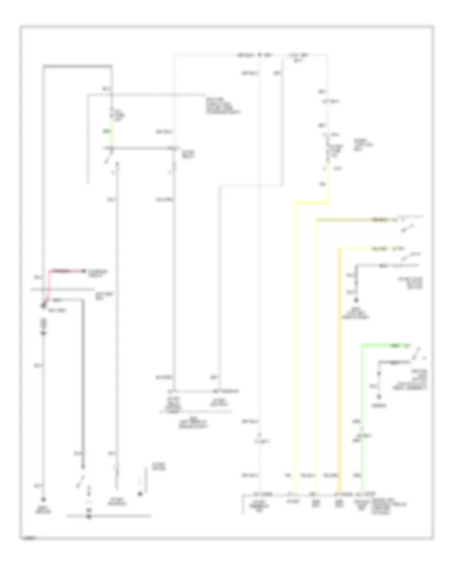
Immobilizer Wiring Diagram, with Smart Key System (2 of 2) for Hyundai Veloster Turbo 2014
List of elements for Immobilizer Wiring Diagram, with Smart Key System (2 of 2) for Hyundai Veloster Turbo 2014:
- (behind left end of front fascia) (1.6l w/o dual clutch) gggg02 (1.6l turbo) gggt01 (1.6l w/ dual clutch) gggd02
- B-can transceiver
- Brk light sw
- C-can transceiver
- Circuit
- Cluster
- Computer data lines system
- Connector joint
- Dd11
- Driver dr ant gnd
- Driver dr ant pwr
- Driver smart key outside handle
- Esc module
- Esc unit
- Exterior lights system
- External buzzer (left front of engine compt)
- Fd11
- Fd21
- Fr11
- Gf01 (left kick panel)
- Gf02 (right kick panel)
- Ground
- High
- Hot at all times
- I/p-e
- I/p-f
- I/p-h
- Immo ind
- Instrument
- Key out ind
- Leak current autocut device
- Lock
- Low
- M13-c
- Mcu
- Memory fuse 10a
- Mf11
- Mf61
- Nca
- Of dash)
- Pass dr ant gnd
- Pass dr ant pwr
- Passenger smart key outside handle
- Pnk
- Power
- Red
- Smart junction box
- Smart key 1 fuse 15a
- Smart key 2 fuse 10a
- Smart key antenna (interior 1) (under center
- Smart key antenna (interior 2) (under rear of floor console)
- Smart key bumper antenna (behind center of rear bumper)
- Smart key control module (center of dash)
- Smart key trunk antenna (center rear of luggage compt)
- Ssb ign
- Ssb ill gnd
- Ssb ill power
- Ssb off
- Stop lp fuse 15a
- Stop signal relay (left side of dash)
- Uda
- Udb connector joint
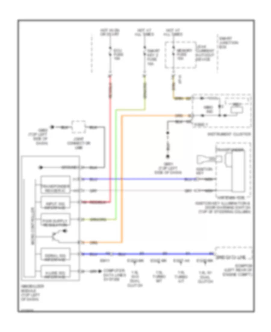
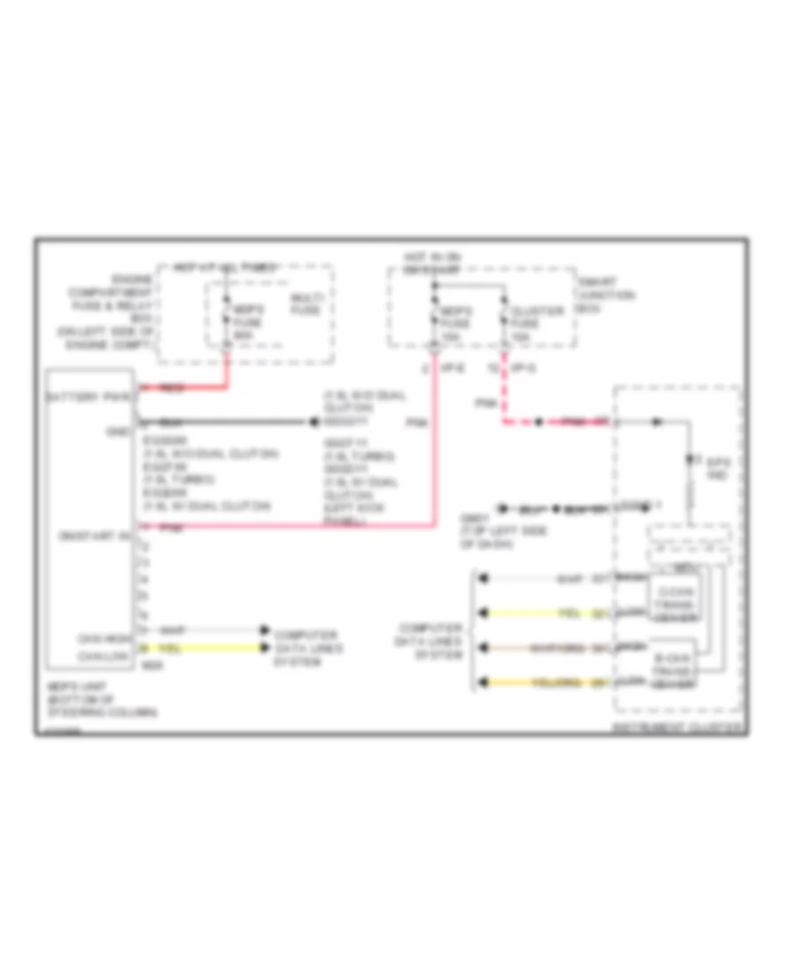
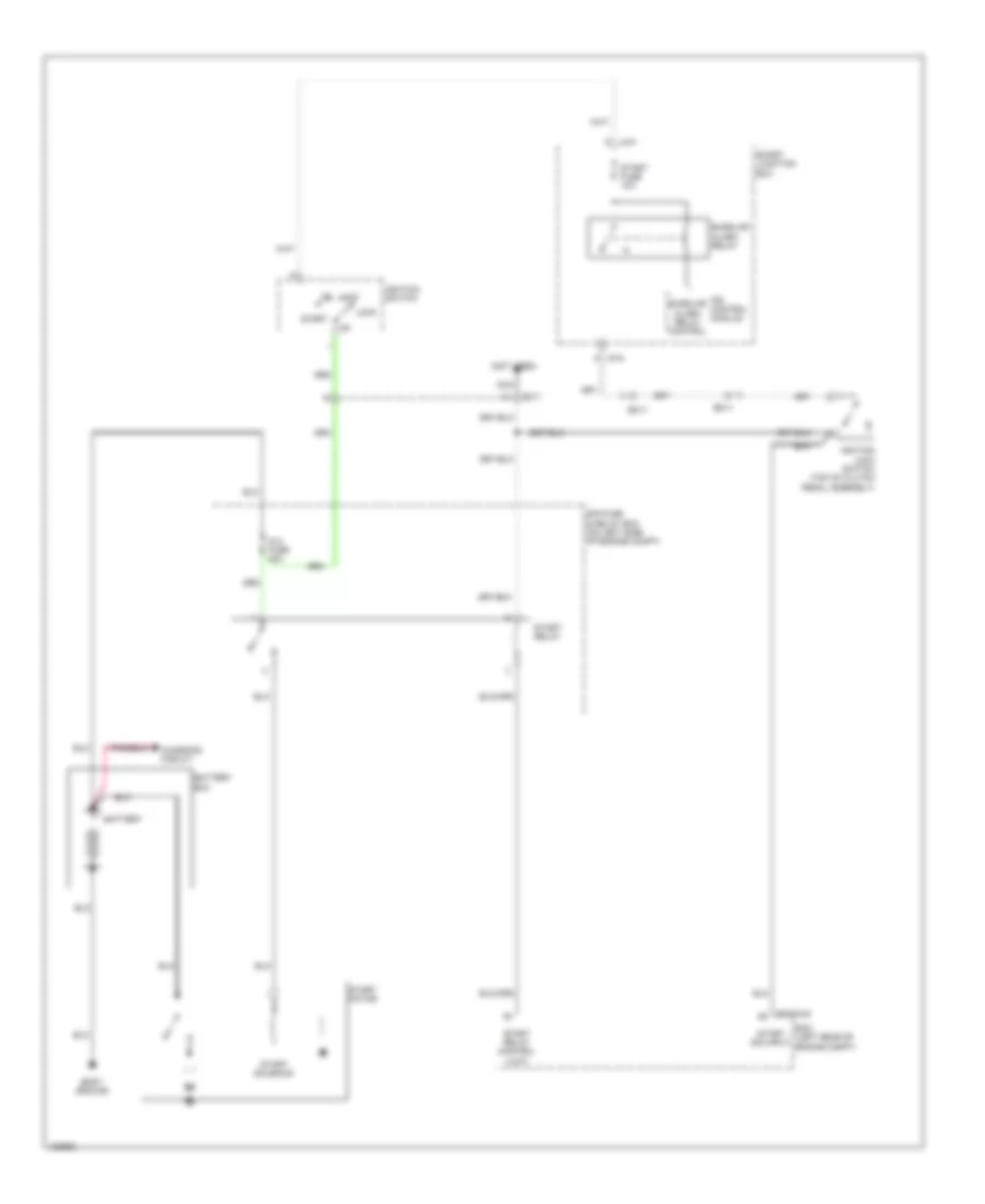
Immobilizer Wiring Diagram, without Smart Key System for Hyundai Veloster Turbo 2014
List of elements for Immobilizer Wiring Diagram, without Smart Key System for Hyundai Veloster Turbo 2014:
- (+)
- (-)
- 1.6l turbo a/t
- 1.6l turbo m/t
- 1.6l w/ dual clutch
- 1.6l w/o dual clutch
- Antenna coil
- Computer data lines system
- Ecm/pcm (left rear of engine compt)
- Ecu fuse 10a
- Eggd-mk
- Eggg-mk
- Eggt-ak
- Eggt-mk
- Em11
- Gm01 (top left side of dash)
- Gm02 (top left side of dash)
- Ground
- Hot at all times
- Hot in on or start
- I/p-h
- Ignition key
- Ignition key illumination & door warning switch (top of steering column)
- Immo data line
- Immo ind
- Immobilizer module (top left of dash)
- Input sig interface
- Instrument cluster
- Joint connector umb
- K-line sig interface
- Leak current autocut device
- Mcu
- Memory fuse 10a
- Micro controller
- Nca
- Serial sig interface
- Sgnd 1
- Smart junction box
- Smart key 2 fuse 10a
- Transponder
- Transponder reader ic
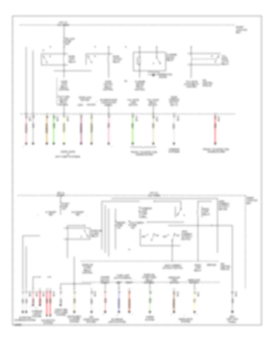
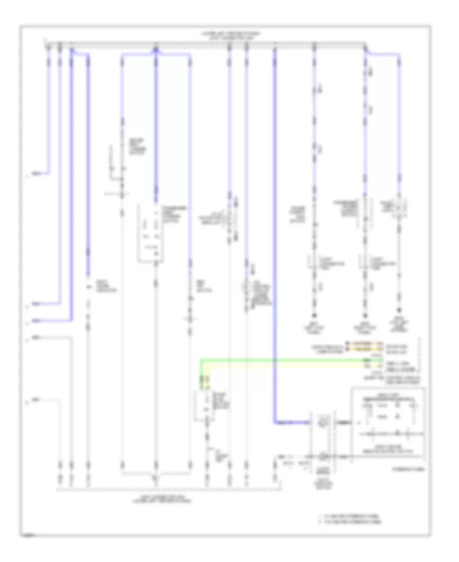
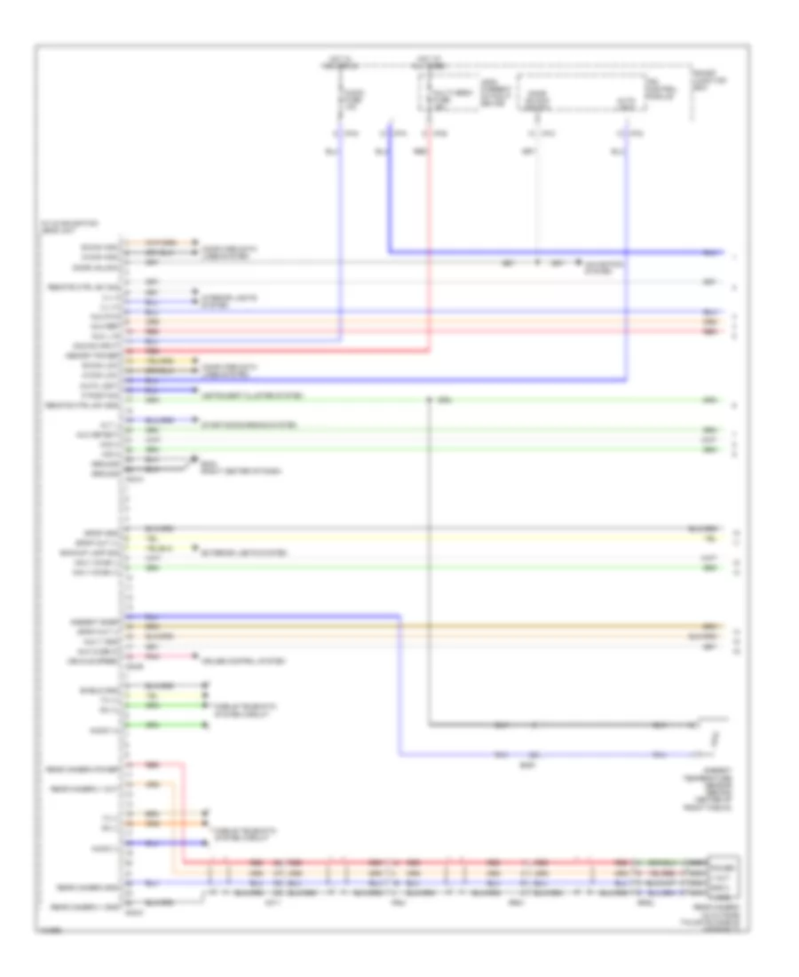
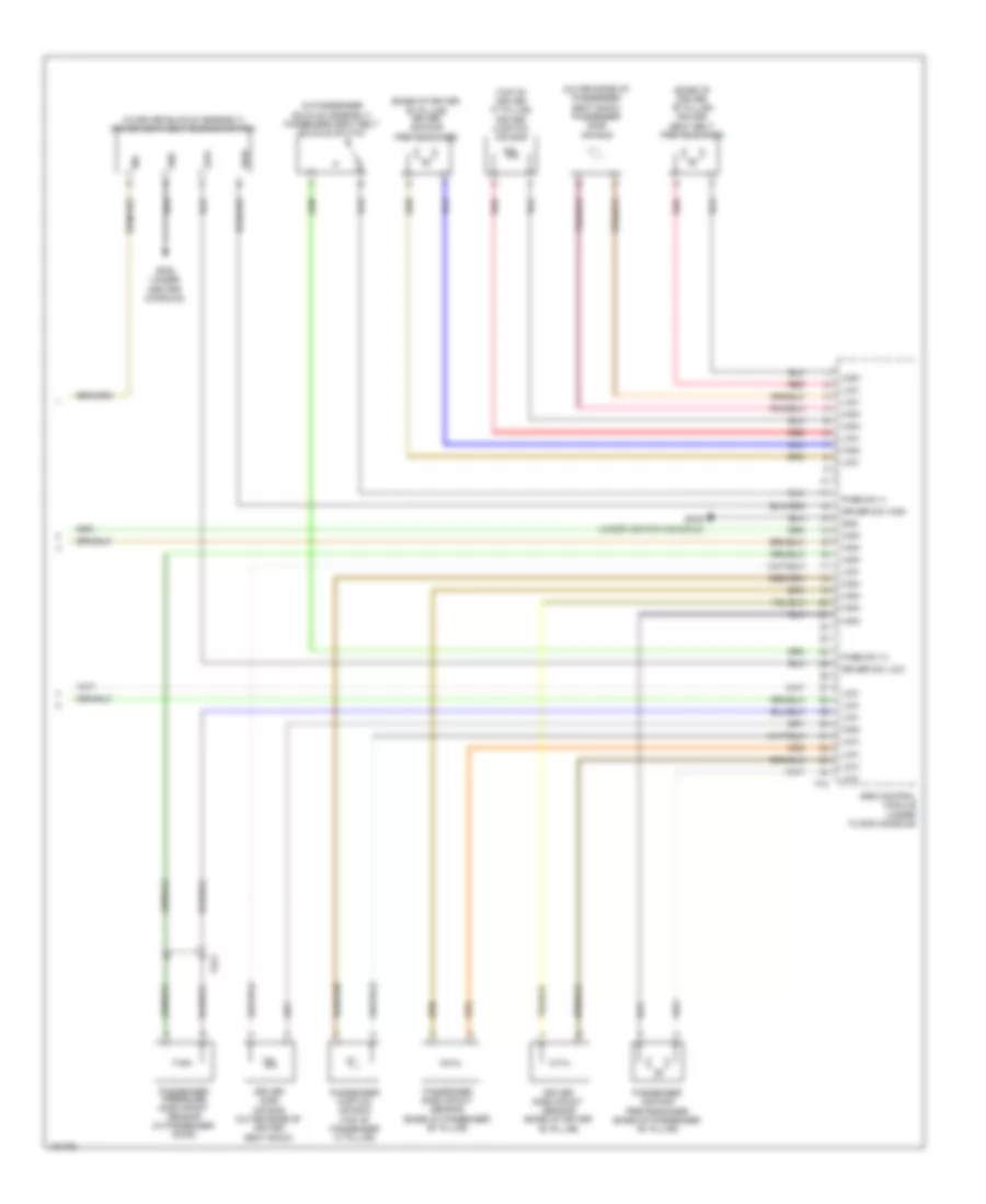
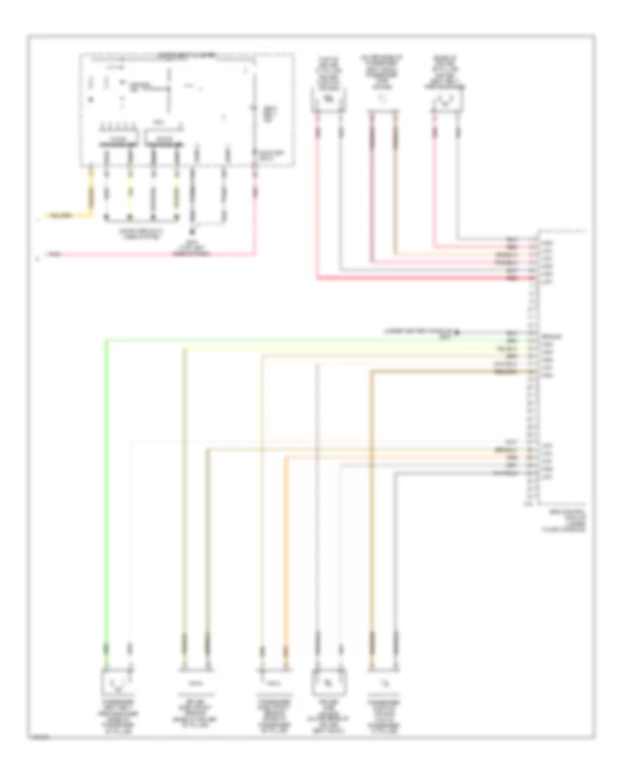
BODY CONTROL MODULES
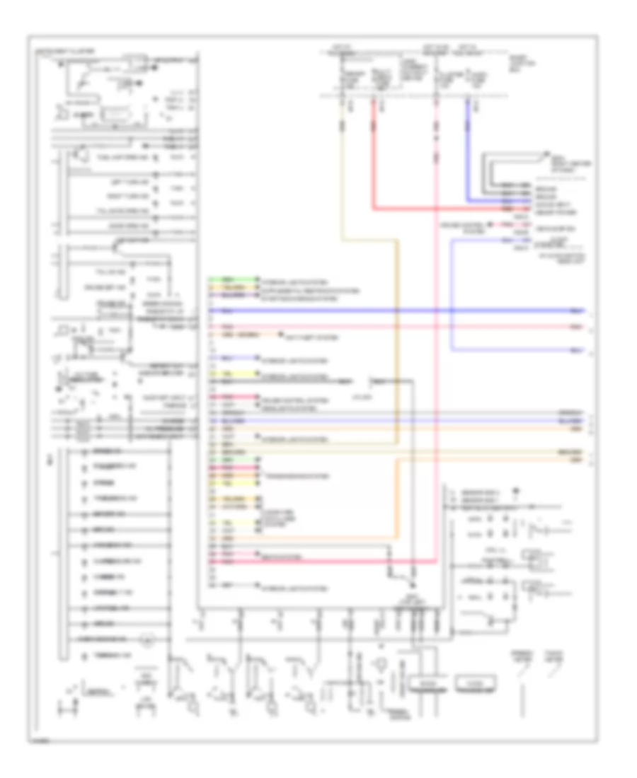
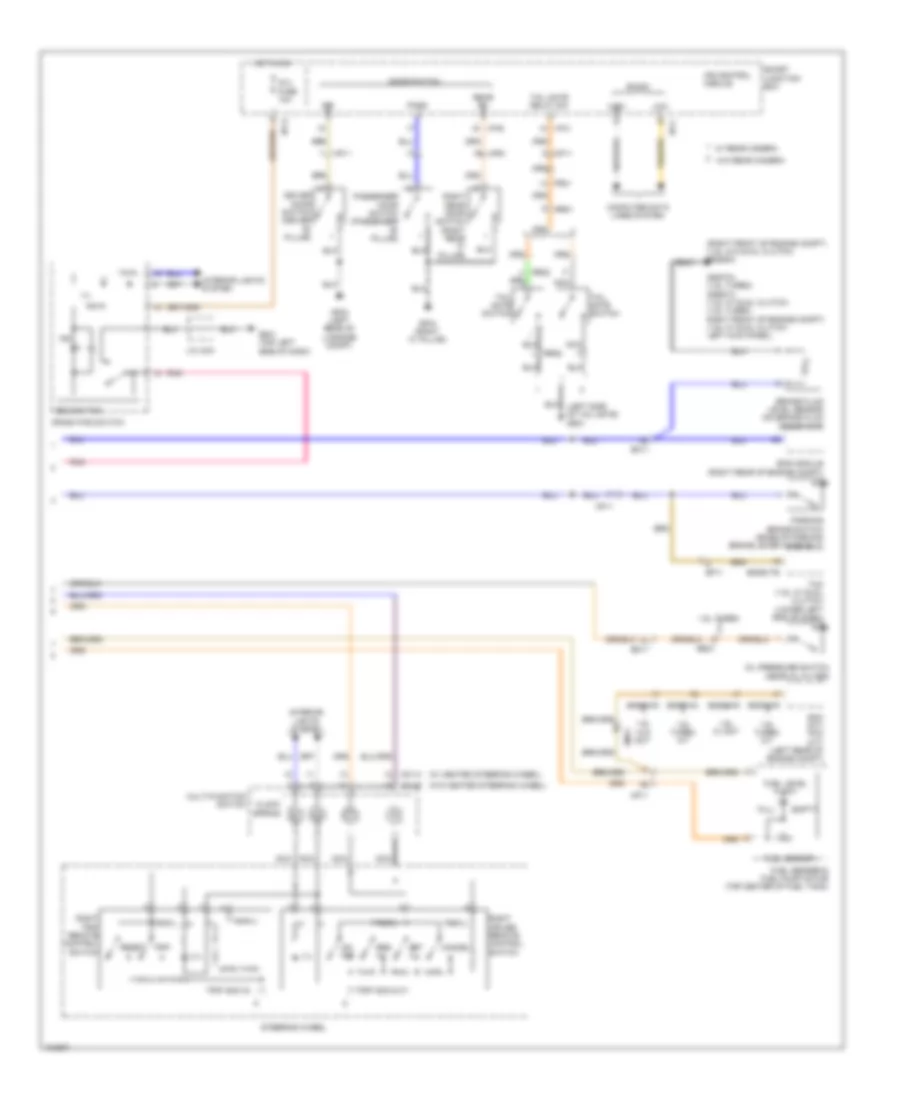
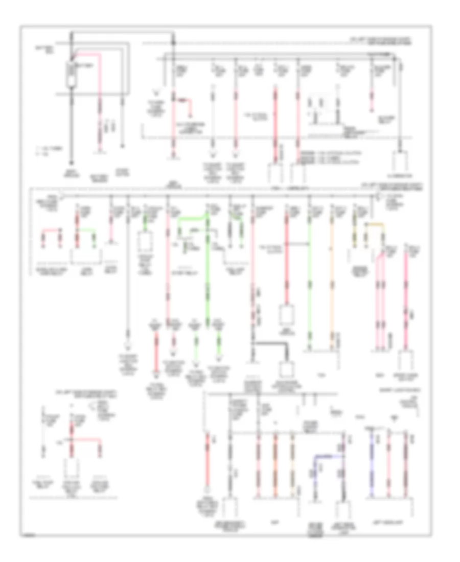
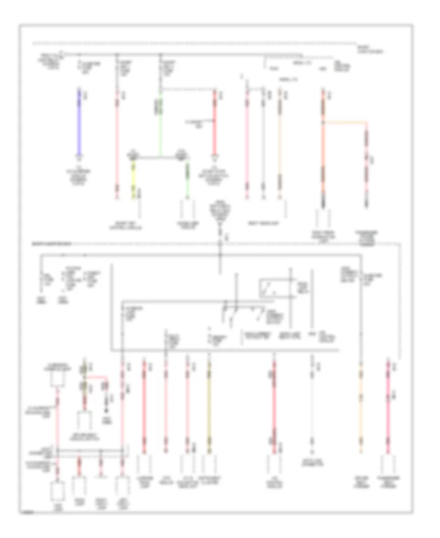
Body Control Modules Wiring Diagram (1 of 3) for Hyundai Veloster Turbo 2014
List of elements for Body Control Modules Wiring Diagram (1 of 3) for Hyundai Veloster Turbo 2014:
- Acc input
- Adc
- Arisu lt 1
- Arisu lt 2
- Audio fuse 10a
- B+2 fuse 50a
- B+3 fuse 50a
- B-can high
- B-can low
- Cluster fuse 10a
- Computer data lines system
- E/r fuse & relay box (on left side of engine compt)
- Exterior lights system
- Headlights & interior lights systems
- Headlights system
- Hot at all times
- Hot in acc or on
- Hot in on
- Hot in on or start
- I/p-a
- I/p-b
- I/p-c
- I/p-e
- I/p-g
- I/p-k
- I/p-l
- I/p-m
- I/p-n
- Ig 1 fuse 10a
- Ig 2 fuse 10a
- Interior lights system
- Ips control module
- Multi fuse
- On input
- On/start input
- P/wdw lh fuse 25a
- P/wdw rh fuse 25a
- Pnk
- Power distribution system
- Power window relay
- Power window relay control
- Power windows system
- Pwm
- Rear fog lamp relay
- Rear fog lamp switch
- Red
- Safety power window
- Smart junction box
- Tail lamp lh fuse 10a
- Tail lamp relay
- Tail lamp relay control
- Tail lamp rh fuse 10a
- Tail lamp switch
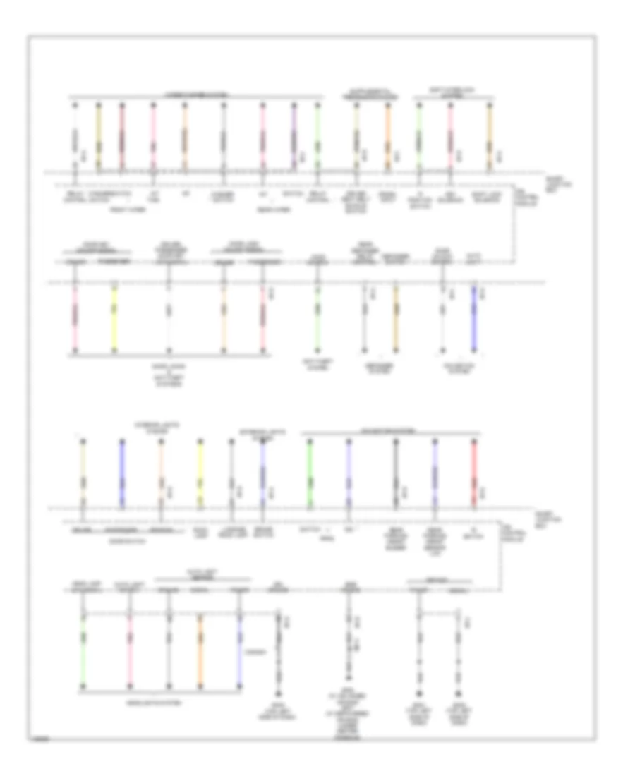
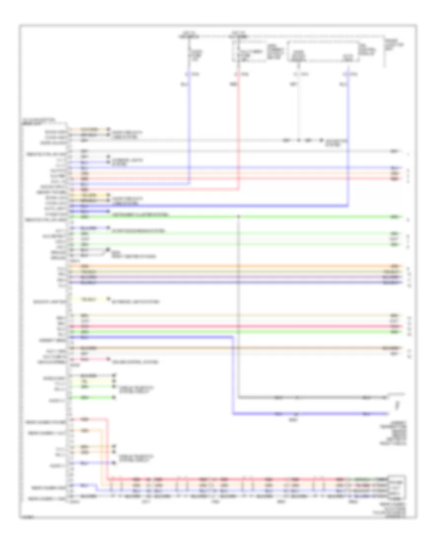
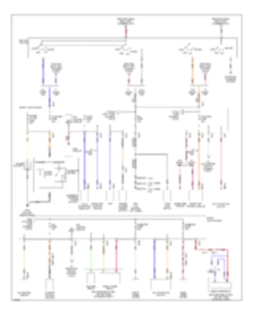
Body Control Modules Wiring Diagram (2 of 3) for Hyundai Veloster Turbo 2014
List of elements for Body Control Modules Wiring Diagram (2 of 3) for Hyundai Veloster Turbo 2014:
- Air conditioning system
- Burglar alarm horn relay control
- Burglar alarm relay
- Burglar alarm relay control
- Computer data lines system
- Door lock relay
- Door lock relay control
- Door lock switch
- Door locks & anti-theft systems
- Door unlock relay
- Door unlock relay control
- Door warning switch key in
- Dr lock fuse 20a
- Exterior lights system
- Flasher sound relay
- Flasher sound relay control
- Gf01 (left kick panel)
- Ground
- Hazard switch signal
- Headlamp high switch
- Headlamp switch
- Headlights system
- Horns system
- Hot at all times
- Hot in start
- I/p-b
- I/p-c
- I/p-d
- I/p-e
- I/p-f
- I/p-h
- I/p-k
- I/p-n
- Instrument cluster system
- Interior lamp fuse 10a
- Interior lights system
- Ips control module
- Leak current autocut device
- Leak current autocut switch
- Leak current on autocut switch
- Left
- Lock
- Memory fuse 10a
- Multimedia fuse 15a
- Navigation system
- Off
- Operation sound
- Red
- Rh rear door lock/unlock signal
- Right
- Room lamp relay
- Smart junction box
- Start fuse 10a
- Starting/ charging system
- Tail gate lamp switch
- Tail gate latch relay
- Tail gate latch relay control
- Tail gate relay switch
- Trunk, tailgate, fuel doors system
- Turn lamp switch signal
- Two turn unlock relay control
- Unlock
- W/ smart key
- W/o smart key
- Warning systems
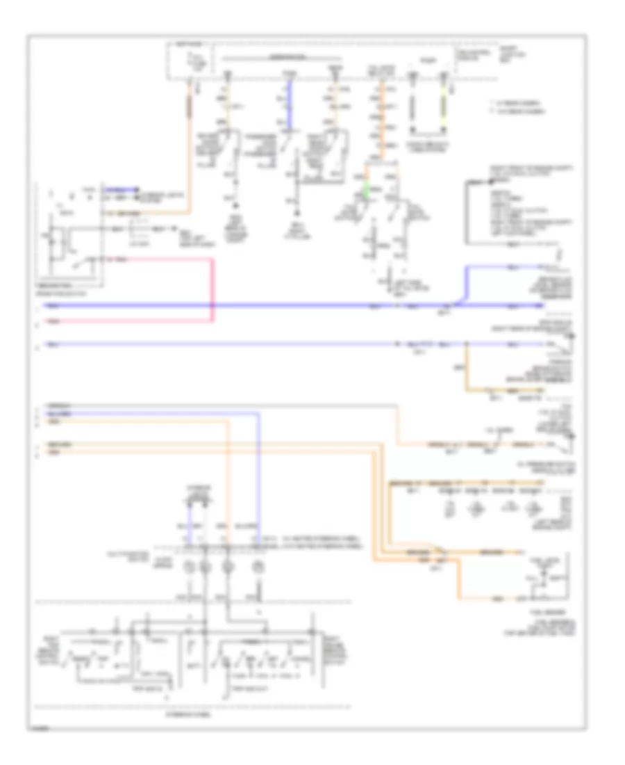
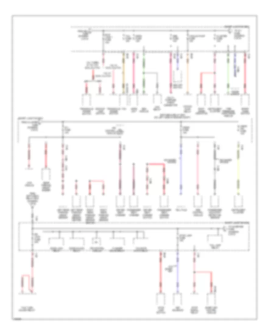
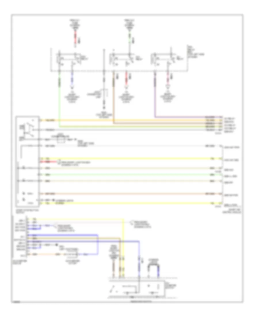
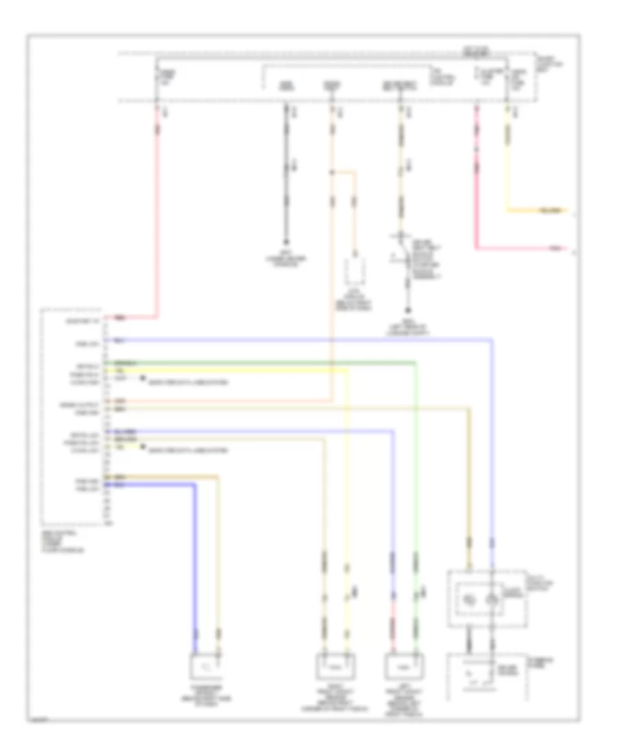
Body Control Modules Wiring Diagram (3 of 3) for Hyundai Veloster Turbo 2014
List of elements for Body Control Modules Wiring Diagram (3 of 3) for Hyundai Veloster Turbo 2014:
- 'p' position switch
- 'r' switch
- Anti-theft system
- Auto light
- Auto light sensor
- Auto light switch
- Brake switch
- Canada
- Crash input
- Defogger switch
- Defogger system
- Door key unlock signal
- Door lock/ unlock signal
- Door locks & anti-theft systems
- Door switch
- Door unlock switch
- Driver
- Driver seat belt buckle switch
- Driver/ passenger door key lock signal
- Drl ground
- Exterior lights system
- Front wiper
- Gf05 (w/ advanced air bag) gf07 (w/ depowered air bag) (under center console)
- Gm01 (top left side of dash)
- Gm02 (top left side of dash)
- Ground
- Head lamp low signal
- Headlights system
- Hood switch
- I/p-a
- I/p-b
- I/p-c
- I/p-d
- Ind
- Int
- Int time
- Interior lights system
- Ips control module
- Key solenoid
- Luggage room lamp
- Mf11
- Navigation system
- Passenger
- Pnk
- Power
- Rear defogger relay control
- Rear parking assist buzzer
- Rear parking assist sensor (lin)
- Rear rh
- Rear wiper
- Red
- Relay control
- Room lamp
- Rpas
- Shift interlock system
- Shift lock solenoid
- Side air bag
- Signal
- Smart junction box
- Switch
- Washer switch
- Wiper/washer system
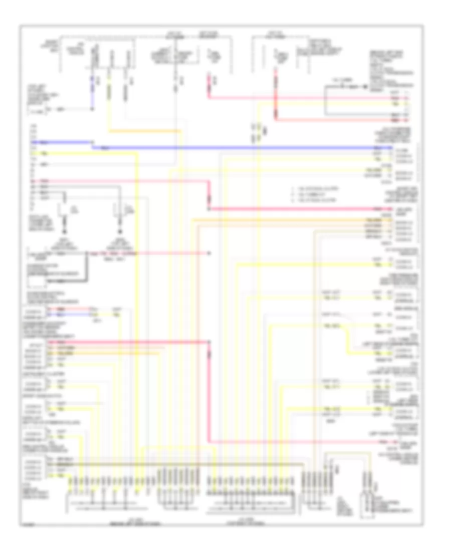
COMPUTER DATA LINES
Computer Data Lines Wiring Diagram for Hyundai Veloster Turbo 2014
List of elements for Computer Data Lines Wiring Diagram for Hyundai Veloster Turbo 2014:
- (behind left end of front fascia) (1.6l turbo) gggt01 (1.6l w/ dual clutch transmission) gggd01 (1.6l w/o dual clutch transmission) gggg01
- (bottom of steering column)
- (top left of dash) (w/o smart key) immobilizer module
- (under passenger's seat)
- 1.6l turbo
- 1.6l turbo m/t
- 1.6l w/ dual clutch
- 1.6l w/o dual clutch
- 4p out
- A/c control module (under center console)
- A/v & navigation headunit
- Abs 2 fuse 30a
- Abs fuse 10a
- B-can hi
- B-can lo
- C-can hi
- C-can lo
- Data link connector
- Data link connector (lower left end of dash)
- E/r fuse & relay box (on left side of engine compt)
- Ecm (left rear of engine compt)
- Eggd-mk
- Eggd-tb
- Eggg-mk eggt-mk
- Eggt-ak
- Em61
- Esc module
- F02-a
- Gm01 (top left side of dash)
- Gm02 (top left side of dash)
- Hot at all times
- Hot in on or start
- I/p-c
- I/p-d
- I/p-h
- I/p-n
- Instrument cluster
- Ips control module
- J/c jm01 (behind left side of dash)
- J/c jm03 (right center of dash)
- J/c jm05 (top right of dash)
- J/c uma
- J/c umb
- K line
- K-line
- Leak current autocut device
- M-can hi
- M-can lo
- M-can lo amp (if equipped) (under passenger's seat)
- M02-a
- M02-b
- M13-a
- M13-b
- M26
- M51
- Mdps unit
- Memory fuse 10a
- Mf11
- Mf61
- Mr11
- Mts module (below right side of dash)
- Multi fuse
- Multipurpose check connector (in engine compt fuse & relay box)
- Nca
- Passenger occupant detection sensor (advanced a/bag)
- Pcm (1.6l turbo a/t) (left rear of engine compt)
- Pnk
- Red
- Rr03
- Smart junction box
- Smart key control module (w/ smart key) (center of dash)
- Sport mode switch
- Srs control module (under floor console)
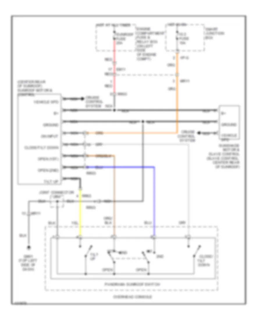
- Sunroof motor & control (center rear of sunroof)
- Sunshade motor & slave control (center rear of sunroof)
- Tcm (1.6l w/ dual clutch) (lower left end of dash)
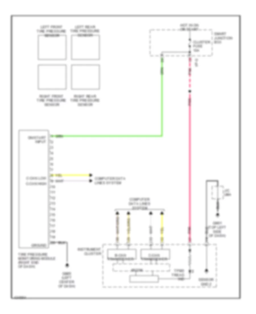
- Tire pressure monitoring module (right end of dash)
- Vacuum pump (1.6l turbo) (left side of transaxle)
- Veh spd snsr
- Veh spd snsr m21-b
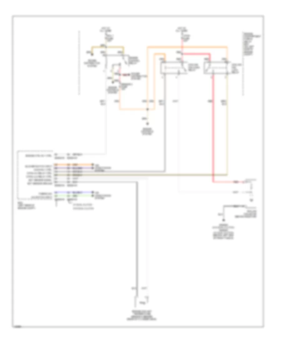
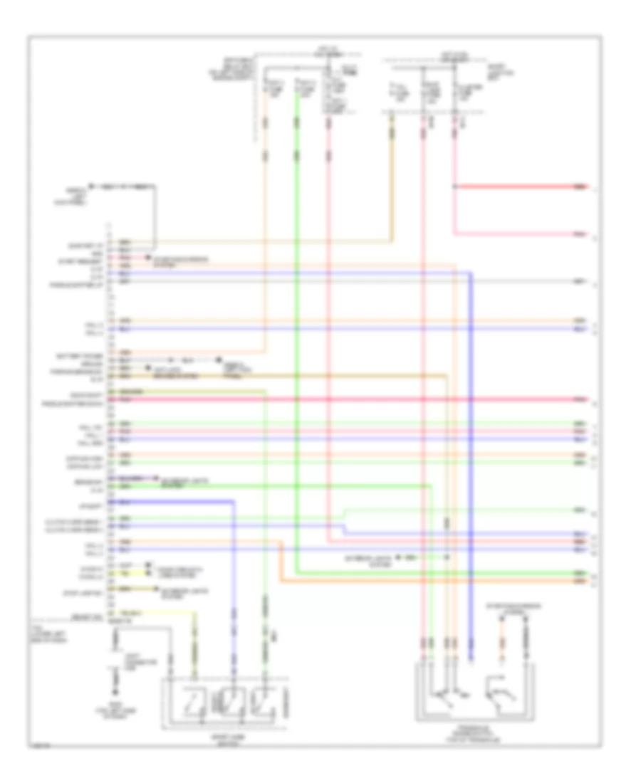
COOLING FAN
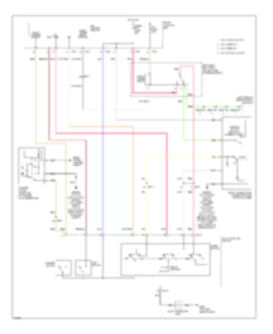
1.6L
1.6L, Cooling Fan Wiring Diagram for Hyundai Veloster Turbo 2014
List of elements for 1.6L, Cooling Fan Wiring Diagram for Hyundai Veloster Turbo 2014:
- A/c switch input
- A/con rly ctrl
- Air conditioning system
- Blower switch input
- C/fan (hi) relay ctrl
- C/fan (lo) relay ctrl
- C/fan fuse 40a
- Control relay
- Cooling
- Cooling fan (low) relay
- Cooling fan motor (behind radiator)
- Ecm (left rear of engine compt)
- Ect sensor ground
- Ect sensor signal
- Ecu 1 fuse 30a
- Eggd-ma
- Eggd-mk
- Eggg-ma
- Eggg-mk
- Engine
- Engine compartment fuse & relay box (on left side of engine compt)
- Engine controls system
- Engine coolant temperature sensor & sender (rear of cylinder head)
- Engine ctrl rly ctrl
- Fan (high) relay
- Gggg02 (w/o dual clutch) gggd02 (w/ dual clutch) (behind left end of front fascia)
- Hot at all times
- Power distribution system
- Red
- Sensor 2 fuse 10a
- Thermo sw
- W/ dual clutch
- W/o dual clutch
1.6L TURBO
1.6L Turbo, Cooling Fan Wiring Diagram for Hyundai Veloster Turbo 2014
List of elements for 1.6L Turbo, Cooling Fan Wiring Diagram for Hyundai Veloster Turbo 2014:
- A/c switch input
- A/con relay control
- A/t
- Air conditioning system
- Blower switch input
- C/fan fuse 60a
- Control relay
- Cooling
- Cooling fan controller (left front of engine compt)
- Cooling fan pwm control
- Ecm (left rear of engine compt)
- Ect sensor ground
- Ect sensor signal
- Ecu 1 fuse 30a
- Eggt-aa
- Eggt-ak
- Eggt-ma
- Eggt-mk
- Eggt12
- Eggt91
- Eggtcr
- Engine
- Engine compartment fuse & relay box (on left side of engine compt)
- Engine controls system
- Engine coolant temperature sensor & sender (rear of cylinder head)
- Engine ctrl rly ctrl
- Fan (high) relay
- Gggt01 (behind left end of front fascia)
- Gggt02 (behind left end of front fascia)
- Hot at all times
- M/t
- Micom
- Nca
- Pnk
- Power conditioning
- Power distribution system
- Radiator fan motor
- Red
- S/r
- Sensor 2 fuse 10a
- Temp
- Thermo switch
CRUISE CONTROL
Cruise Control Wiring Diagram (1 of 2) for Hyundai Veloster Turbo 2014
List of elements for Cruise Control Wiring Diagram (1 of 2) for Hyundai Veloster Turbo 2014:
- (1.6l turbo m/t: left rear of engine compt)
- 1.6l
- 1.6l turbo a/t
- 1.6l turbo m/t
- 1.6l w/ dual clutch
- 1.6l w/o dual clutch
- A/c control module (under center console)
- A/v & navigation head unit
- Accel pedal position sensor (top of accelerator pedal assembly)
- Aps 1 gnd
- Aps 1 sig
- Aps 2 gnd
- Aps 2 sig
- Brake test sw
- Cluster fuse 10a
- Clutch sw
- Cruise clutch switch (top of clutch pedal assembly)
- Data link connector (lower left end of dash)
- Ecm (1.6l & 1.6l turbo m/t) pcm (1.6l & 1.6l turbo a/t) (left rear of engine compt)
- Ecu 1 fuse 10a
- Eggd-ma
- Eggd-mk
- Eggg-ma
- Eggg-mk
- Eggt-aa
- Eggt-ak
- Eggt-ma
- Eggt-mk
- Em11
- Etc motor & throttle position sensor (on throttle body)
- Etc output (+)
- Etc output (-)
- Exterior
- Gggg02 (1.6l w/o dual clutch) gggt07 (1.6l turbo m/t) (1.6l w/o dual clutch: behind left end of front fascia)
- Hot at all times
- Hot in on or start
- I/p-g
- I/p-h
- I/p-m
- I/p-n
- Leak current autocut device
- Lights system
- M02-b
- M21-b
- Memory fuse 10a
- Motor
- Mr11
- Nca
- On start input
- Pnk
- Red
- Rr03
- Smart junction box
- Speed input
- Stop lamp fuse 15a
- Stop lamp switch (top of brake pedal assembly)
- Stop lt sw
- Stop signal relay (left side of dash)
- Sunroof motor & control (center rear of sunroof)
- Sunshade motor & slave control
- Throttle position sensor
- Tps 1 sig
- Tps 2 sig
- Tps gnd
- Vehicle
- W/ dual clutch
- W/o dual clutch
- W/o dual clutch & 1.6l turbo
Cruise Control Wiring Diagram (2 of 2) for Hyundai Veloster Turbo 2014
List of elements for Cruise Control Wiring Diagram (2 of 2) for Hyundai Veloster Turbo 2014:
- (+)
- (-)
- B-can transceiver
- C-can high
- C-can low
- C-can transceiver
- Can- cel
- Clock spring
- Computer data lines
- Computer data lines system
- Cruise ind
- Cruise set ind
- Ef11
- Em61
- Esc module
- Esc unit
- Fl vcc
- Fr sig
- Fr vcc
- Gm01 (top left side of dash)
- High
- Ill
- Instrument cluster
- Interior lights system
- Left front wheel sensor (left front wheel hub assembly)
- Left rear wheel sensor (left rear wheel hub assembly)
- Low
- M13-b
- Mcu
- Memory pwr
- Multi-function switch
- Nca
- On/ off
- On/start
- Output
- Pnk
- Red
- Rese+
- Right cruise remote control switch
- Right front wheel sensor (right front wheel hub assembly)
- Right rear wheel sensor (right rear wheel hub assembly)
- Rl sig
- Rl vcc
- Rr sig
- Rr vcc
- Set-
- Sgnd1
- Sgnd2
- Smart key control module (center of dash)
- Speedometer
- Steering wheel
- System
- Tachometer
- Trip (+)
- Trip (-)
- W/ heated steering wheel
- W/o heated steering wheel
- Wheel sens o/p (f/r) fl sig
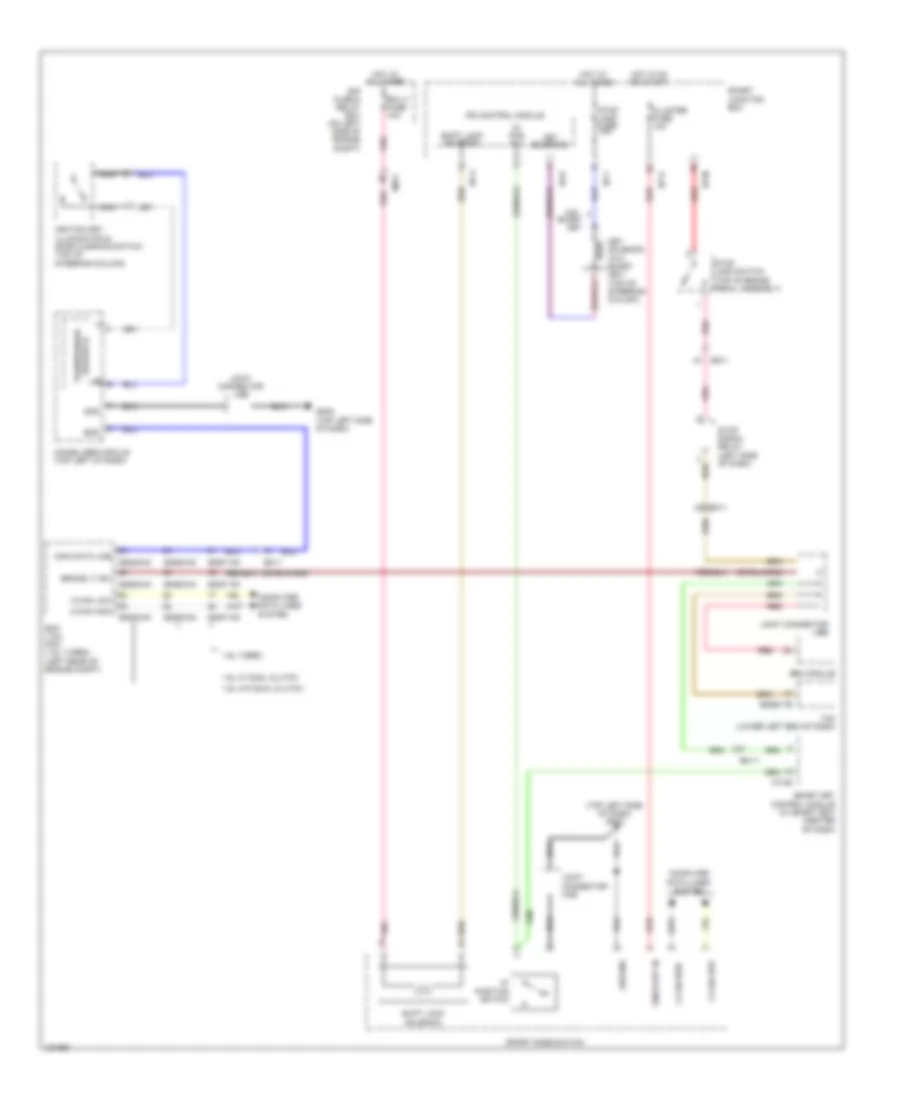
DEFOGGERS
Defoggers Wiring Diagram for Hyundai Veloster Turbo 2014
List of elements for Defoggers Wiring Diagram for Hyundai Veloster Turbo 2014:
- (left rear of engine compt) (except 1.6l turbo a/t) ecm (1.6l turbo a/t) pcm
- 1.6l
- 1.6l turbo
- 1.6l turbo a/t
- 1.6l turbo m/t
- 1.6l w/ dual clutch
- 1.6l w/o dual clutch
- A/c control module (under center console)
- B-can
- Computer data lines system
- Defogger
- Defogger switch
- Driver power outside mirror
- Eggd-ma
- Eggg-ma
- Eggt-ak
- Eggt-ma
- Elec load-defro (act hi)
- Em11
- Engine compt fuse & relay box (on left side of engine compt)
- Fd11
- Fd21
- Fr21
- Gf01 (left kick panel)
- Gf02 (right kick panel)
- Gm01 (top left side of dash)
- Gnd
- Gr01 (left side of tailgate)
- High
- Hot at all times
- Htd mirr fuse 10a
- I/p-a
- I/p-c
- I/p-h
- I/p-k
- I/p-l
- Ind
- Ips control module
- Joint connector uda
- Joint connector udb
- Joint connector uma
- Low
- M21-b
- Multi fuse
- Nca
- Off
- Passenger power outside mirror
- Pnk
- Quarter panel ground
- R10
- R15
- Rear defogger
- Rear defogger 1
- Rear defogger 2
- Red
- Relay
- Rr def rly ctrl
- Rr htd fuse 40a
- Smart junction box
- Switch
ELECTRONIC POWER STEERING
Electronic Power Steering Wiring Diagram for Hyundai Veloster Turbo 2014
List of elements for Electronic Power Steering Wiring Diagram for Hyundai Veloster Turbo 2014:
- (1.6l w/o dual clutch) gggg11
- B-can trans- ceiver
- Battery pwr
- C-can trans- ceiver
- Can high
- Can low
- Cluster fuse 10a
- Computer data lines
- Computer data lines system
- Eggg66 (1.6l w/o dual clutch) eggt66 (1.6l turbo) eggd66 (1.6l w/ dual clutch)
- Engine compartment fuse & relay box (on left side of engine compt)
- Eps ind
- Gggt11 (1.6l turbo) gggd11 (1.6l w/ dual clutch) (left kick panel)
- Gm01 (top left side of dash)
- Gnd
- High
- Hot at all times
- Hot in on or start
- I/p-e
- I/p-g
- Instrument cluster
- Low
- M26
- Mcu
- Mdps fuse 10a
- Mdps fuse 80a
- Mdps unit (bottom of steering column)
- Multi fuse
- On/start in
- Pnk
- Red
- Sgnd 1
- Smart junction box
- System
ENGINE PERFORMANCE
1.6L
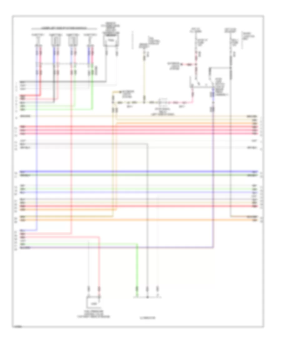
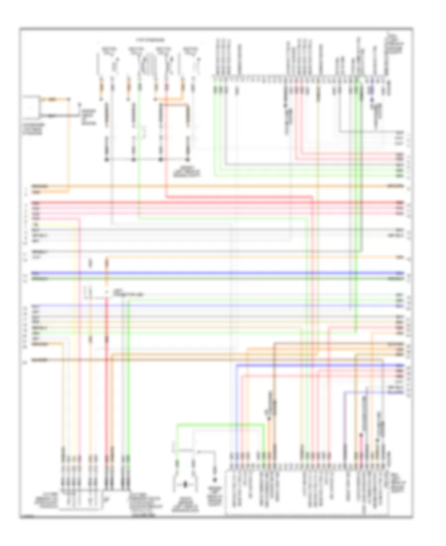
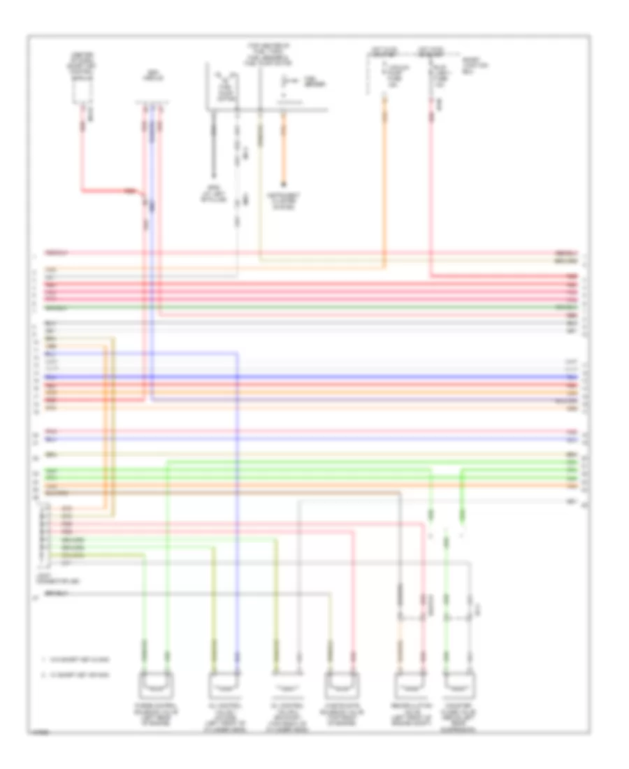
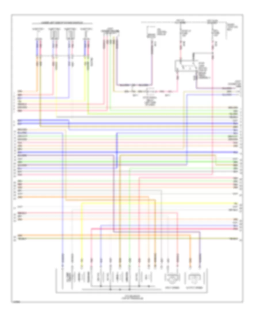
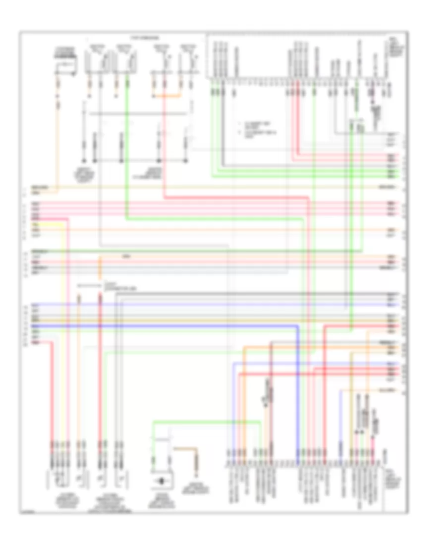
1.6L, Engine Performance Wiring Diagram, with DCT (1 of 5) for Hyundai Veloster Turbo 2014
List of elements for 1.6L, Engine Performance Wiring Diagram, with DCT (1 of 5) for Hyundai Veloster Turbo 2014:
- A/c pressure transducer (lower right rear of engine compt)
- Alt fuse 125a
- Ams fuse 10a
- Apt gnd
- Battery
- Battery box
- Body ground
- C-can hi
- C-can lo
- Ccp can hi
- Ccp can lo
- Ckps gnd
- Ckps sig
- Cmps gnd
- Cmps sig
- Computer data lines system
- E/r fuse & relay box (on left side of engine compt)
- Ecm (left rear of engine compt)
- Ecu 1 fuse 30a
- Ecu 2 fuse 15a
- Ecu 4 fuse 15a
- Ef11
- Eggd-mk
- Eggdinj
- Eng ctrl rly ctrl
- Engine control relay
- F/pump fuse 15a
- Fuel pump relay
- Fuel pump rly ctrl (or ccv ctrl)
- Fuel tank pressure sensor (part of fuel sender & fuel pump motor assembly)
- Iat sig
- Immo data line
- Lin communication
- Lin line
- Map sensor (on throttle body)
- Multi fuse
- Nernst voltage
- Pcsv ctrl
- Pnk
- Pumping current
- Rail pressure sensor (front of fuel rail assembly)
- Red
- Rps gnd
- Rps sig
- Sensor 1 fuse 20a
- Sensor 2 fuse 10a
- Sensor 3 fuse 15a
- Sensor gnd
- Sensor sig
- Snsr +
- Start rly ctrl
- Start sig in
- Starting/ charging system
- Trim resistor
- Vehicle speed in
- Virtual gnd
- W/ smart key & immo
- W/o smart key or immo
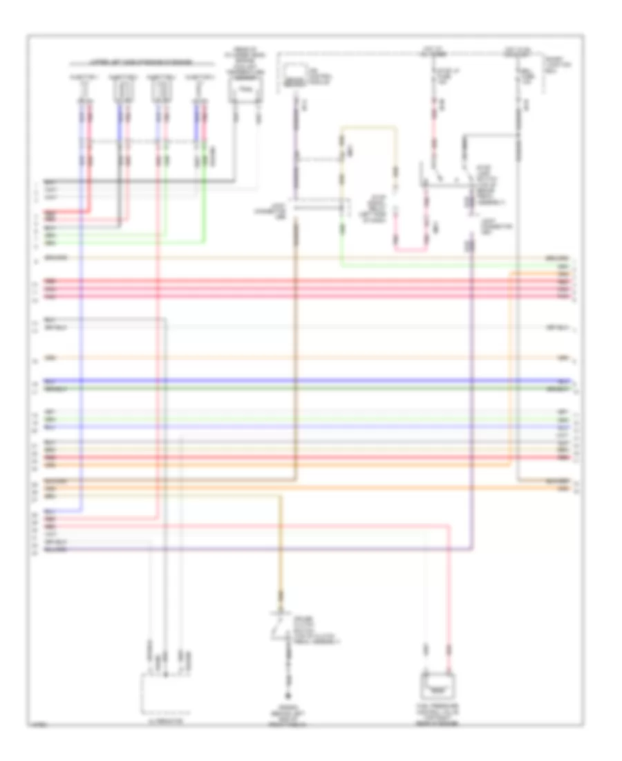
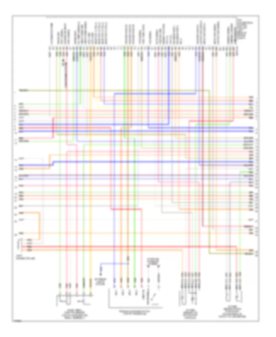
1.6L, Engine Performance Wiring Diagram, with DCT (2 of 5) for Hyundai Veloster Turbo 2014
List of elements for 1.6L, Engine Performance Wiring Diagram, with DCT (2 of 5) for Hyundai Veloster Turbo 2014:
- (center of dash) smart key control module
- (left front of cylinder head)
- (top center of fuel tank) fuel sender & fuel pump motor
- (top front of cylinder head)
- Camshaft position sensor (exhaust) (right rear of cylinder head)
- Camshaft position sensor (intake) (left rear of cylinder head)
- Canister close valve (above left rear suspension)
- Crankshaft position sensor (left rear of engine block)
- Ef11
- Em11
- Em61
- Esc module
- Fuel
- Fuel pump motor
- Gf06 (at left "b" pillar)
- Instrument cluster system
- Joint connector je01
- M13-b
- Mf11
- Oil control valve 1 (intake)
- Oil control valve 2 (exhaust)
- Pnk
- Purge control solenoid valve (left rear of engine)
- Red
- Sender
- Variable intake solenoid valve (left rear of engine)
- W/ smart key & immo
- W/o smart key or immo
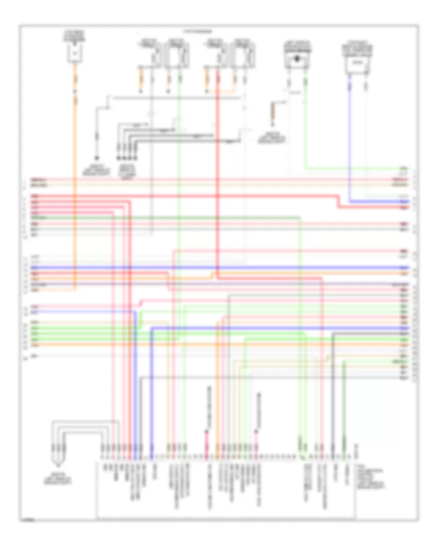
1.6L, Engine Performance Wiring Diagram, with DCT (3 of 5) for Hyundai Veloster Turbo 2014
List of elements for 1.6L, Engine Performance Wiring Diagram, with DCT (3 of 5) for Hyundai Veloster Turbo 2014:
- (rear of engine) gggd09
- (top of engine)
- A/con rly ctrl
- Air
- Alternator com
- Blower sw in
- Brake light sw
- Brake test sw
- C/fan rly ctrl hi
- C/fan rly ctrl lo
- Condenser (top rear of engine)
- Conditioning system
- Cooling fans system
- Cvvt exhaust
- Cvvt intake
- Defogger system
- Ecm (left rear of engine compt)
- Ects gnd
- Ects sig
- Eggd-ma
- Elec load defroster
- Engine rpm output
- Etc output (+)
- Etc output (-)
- Fpcv (+)
- Fpcv (-)
- Ftps sig
- Fuel pump rly ctrl (or ccvt ctrl)
- Gggd06 (left rear of engine compt)
- Gggd07 (left rear of engine compt)
- Ign coil ctrl cyl 1
- Ign coil ctrl cyl 2
- Ign coil ctrl cyl 3
- Ign coil ctrl cyl 4
- Ignition coil 1
- Ignition coil 2
- Ignition coil 3
- Ignition coil 4
- Injector 1 ctrl (+)
- Injector 1 ctrl (-)
- Injector 2 ctrl (+)
- Injector 2 ctrl (-)
- Injector 3 ctrl (+)
- Injector 3 ctrl (-)
- Injector 4 ctrl (+)
- Injector 4 ctrl (-)
- Knock sensor (left side of engine block)
- Knock sensor gnd
- Knock sensor sig
- Nca
- Oxygen sensor (down) (in exhaust, downstream of catalytic converter)
- Oxygen sensor (up) (on exhaust manifold)
- Pnk
- Red
- Sensor heater
- System conditioning air
- System cooling fans
- Vis ctrl
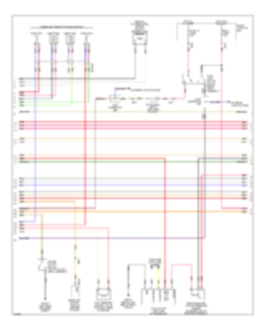
1.6L, Engine Performance Wiring Diagram, with DCT (4 of 5) for Hyundai Veloster Turbo 2014
List of elements for 1.6L, Engine Performance Wiring Diagram, with DCT (4 of 5) for Hyundai Veloster Turbo 2014:
- (rear of cylinder head) engine coolant temperature sensor
- (under left side of intake manifold)
- Alternator
- Brake switch
- Ecu 1 fuse 10a
- Eggginj
- Em11
- Exterior lights system
- Fuel pressure control valve (top right rear of engine)
- Hot at all times
- Hot in on or start
- I/p-a
- I/p-m
- I/p-n
- Injector 1
- Injector 2
- Injector 3
- Injector 4
- Ips control module
- Pnk
- Red
- Smart junction box
- Stop lamp switch (top of brake pedal assembly)
- Stop lp fuse 15a
- Stop signal relay (left side of dash)
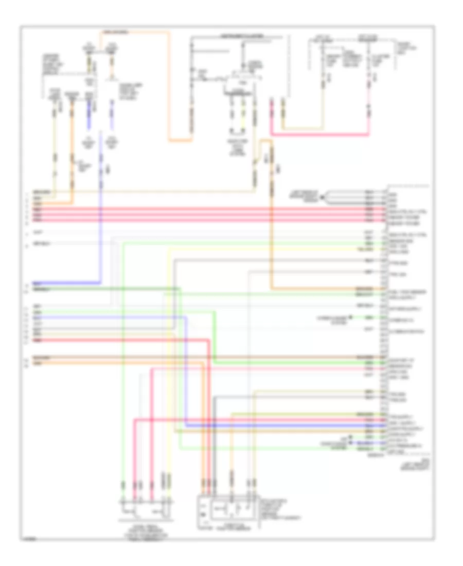
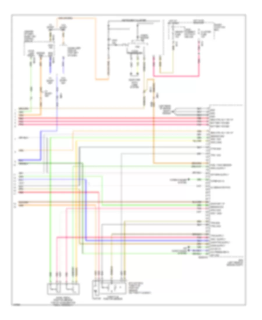
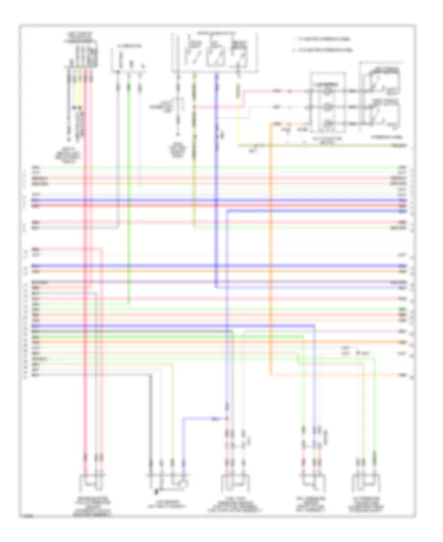
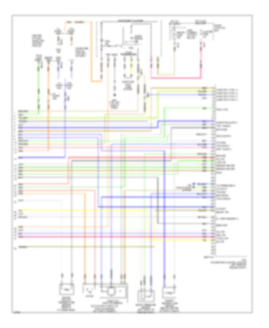
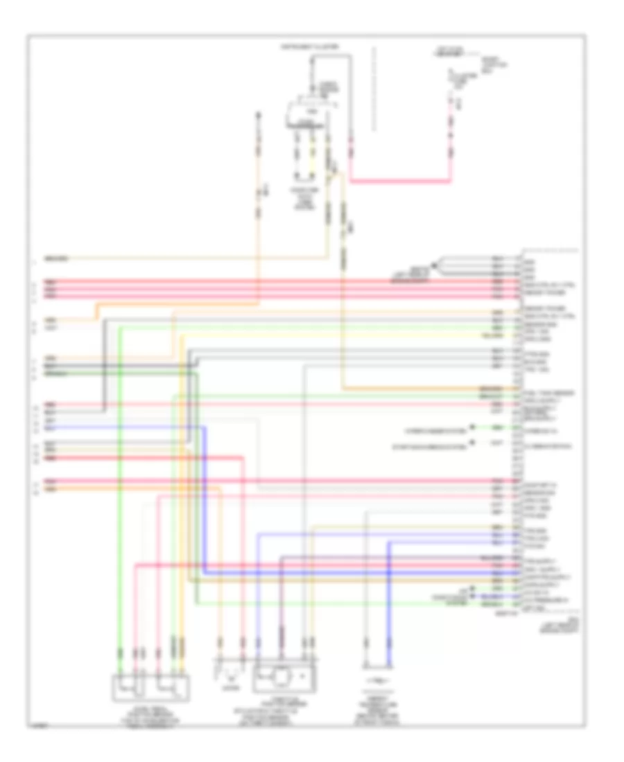
1.6L, Engine Performance Wiring Diagram, with DCT (5 of 5) for Hyundai Veloster Turbo 2014
List of elements for 1.6L, Engine Performance Wiring Diagram, with DCT (5 of 5) for Hyundai Veloster Turbo 2014:
- (center of dash) smart key control module
- (left rear of engine compt) gggd06
- A/c pressure in
- A/c sw in
- Accel pedal position sensor (top of accelerator pedal assembly)
- Air conditioning system
- Alternator pwm
- Aps 1 gnd
- Aps 1 sig
- Aps 2 gnd
- Aps 2 sig
- Apt sig
- C-can transceiver
- Check engine ind
- Cluster fuse 10a
- Computer data lines system
- Ecm (left rear of engine compt)
- Eggd-mk
- Em11
- Ems com
- Eng ctrl rly ctrl
- Engine rpm
- Etc motor & throttle position sensor (on throttle body)
- Ftps gnd
- Fuel tank sensor
- Gnd
- Hot at all times
- Hot in on or start
- I/p-g
- I/p-h
- Immo ind
- Immobilizer module (top left of dash)
- Instrument cluster
- Leak current autocut device
- M13-a
- M13-b
- M13-c
- Mcu
- Memory fuse 10a
- Memory power
- Mf11
- Motor
- On/start i/p
- Pnk
- Red
- Sensor gnd
- Sensor sig
- Smart junction box
- Stop lamp signal
- Throttle position sensor
- Tps gnd
- Tps1 sig
- Tps2 sig
- W/ smart key
- W/o smart key
- Wiper sw in
- Wiper/washer system
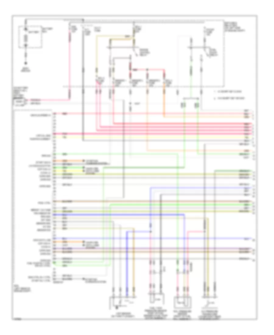
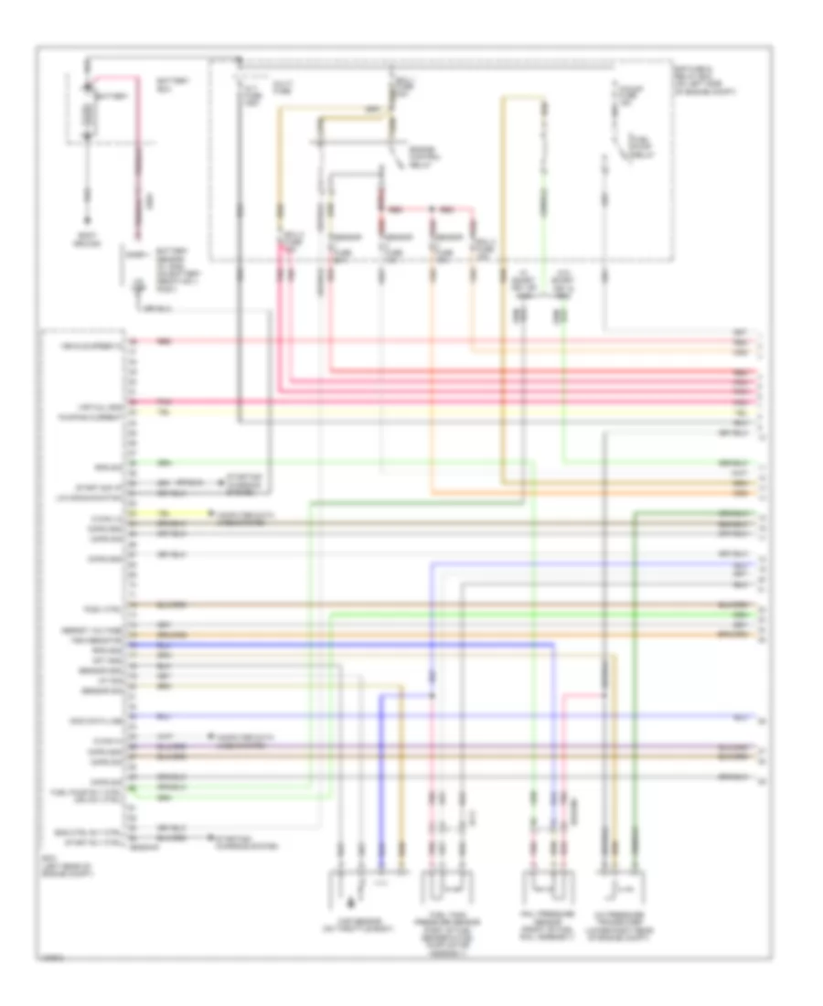
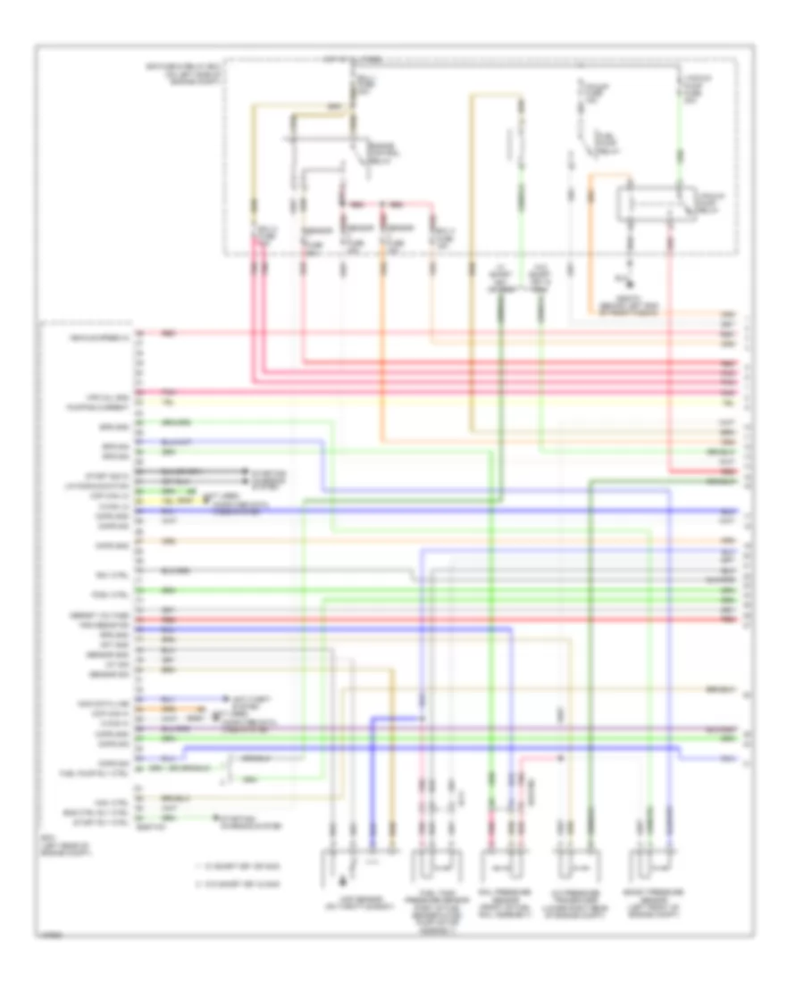
1.6L, Engine Performance Wiring Diagram, without DCT (1 of 5) for Hyundai Veloster Turbo 2014
List of elements for 1.6L, Engine Performance Wiring Diagram, without DCT (1 of 5) for Hyundai Veloster Turbo 2014:
- A/c pressure transducer (lower right rear of engine compt)
- Alt fuse 125a
- Apt gnd
- Battery
- Battery box
- Body ground
- C-can hi
- C-can lo
- Ckps gnd
- Ckps sig
- Cmps gnd
- Cmps sig
- Computer data lines system
- E/r fuse & relay box (on left side of engine compt)
- Ecm (left rear of engine compt)
- Ecu 1 fuse 30a
- Ecu 2 fuse 15a
- Ecu 4 fuse 15a
- Ee01
- Ef11
- Eggg-mk
- Eggginj
- Eng ctrl rly ctrl
- Engine control relay
- Fuel pump relay
- Fuel pump rly ctrl (or ccv ctrl)
- Fuel tank pressure sensor (part of fuel sender & fuel pump motor assembly)
- Iat sig
- Immo data line
- Lin communication
- Lin line
- Map sensor (on throttle body)
- Multi fuse
- Nernst voltage
- Pcsv ctrl
- Pnk
- Pumping current
- Rail pressure sensor (front of fuel rail assembly)
- Red
- Rps gnd
- Rps sig
- Sensor fuse 10a
- Sensor fuse 15a
- Sensor fuse 20a
- Sensor gnd
- Sensor sig
- Snsr +
- Start rly ctrl
- Start sig i/p
- Starting/ charging system
- Trim resistor
- Vehicle speed in
- Virtual gnd
- W/ smart key or immo
- W/o smart key & immo
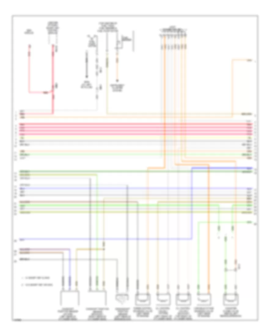
1.6L, Engine Performance Wiring Diagram, without DCT (2 of 5) for Hyundai Veloster Turbo 2014
List of elements for 1.6L, Engine Performance Wiring Diagram, without DCT (2 of 5) for Hyundai Veloster Turbo 2014:
- (at left "b" pillar)
- (center of dash) smart key control module
- (top center of fuel tank) fuel sender & fuel pump motor
- Camshaft position sensor (exhaust) (right rear of cylinder head)
- Camshaft position sensor (intake) (left rear of cylinder head)
- Canister close valve (above left rear suspension)
- Crankshaft position sensor (left rear of engine block)
- Ef11
- Em11
- Em61
- Esc module
- Fuel
- Fuel pump motor
- Gf06
- Instrument cluster system
- Joint connector uec
- M13-b
- Mf11
- Oil control valve 1 (intake) (left front of cylinder head)
- Oil control valve 2 (exhaust) (top front of cylinder head)
- Pnk
- Purge control solenoid valve (left rear of engine)
- Red
- Sender
- Variable intake solenoid valve (left rear of engine)
- W/ smart key or immo
- W/o smart key & immo
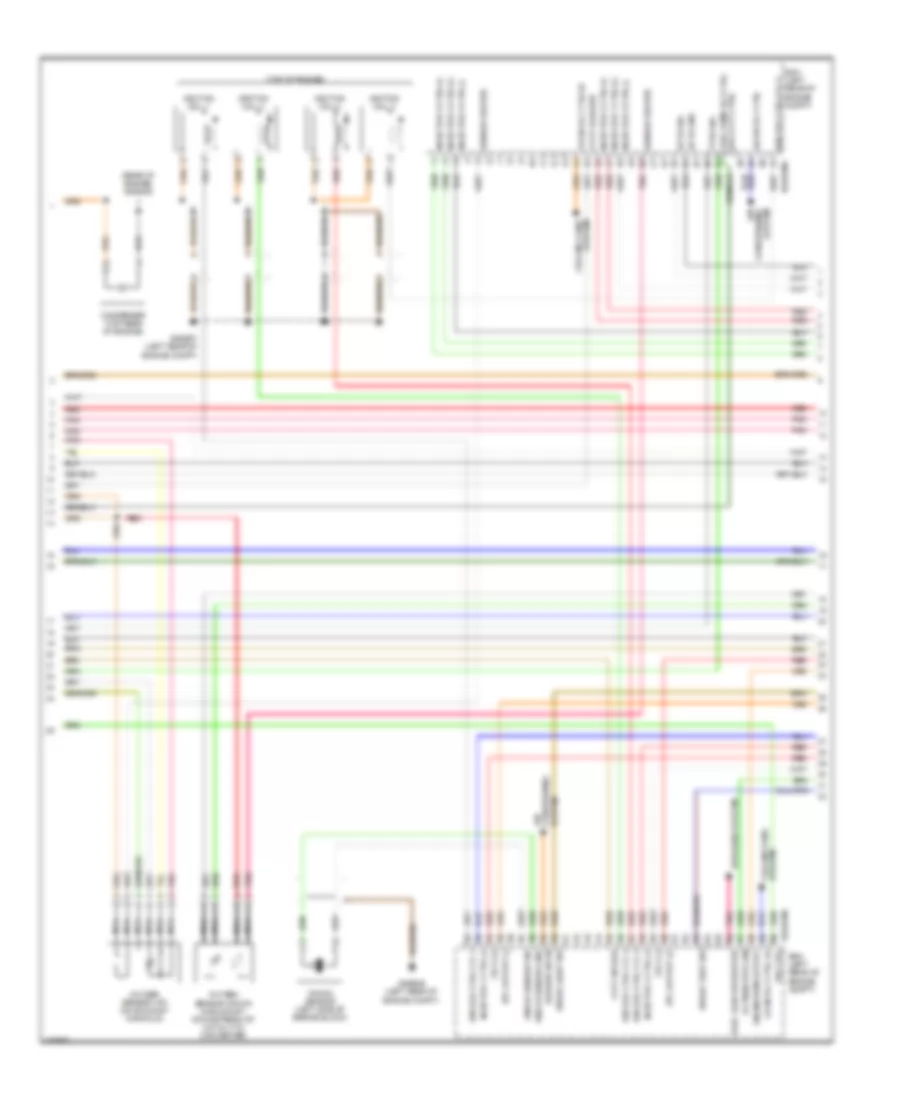
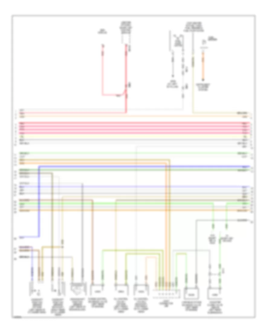
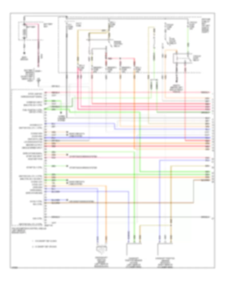
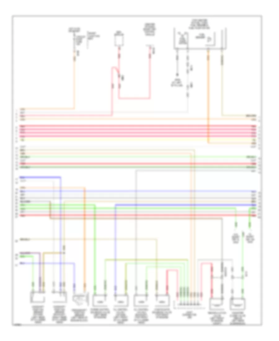
1.6L, Engine Performance Wiring Diagram, without DCT (3 of 5) for Hyundai Veloster Turbo 2014
List of elements for 1.6L, Engine Performance Wiring Diagram, without DCT (3 of 5) for Hyundai Veloster Turbo 2014:
- (or ccv ctrl) fuel pump rly ctrl
- (top of engine)
- A/con rly ctrl
- Air
- Alternator com
- Blower sw in
- Brake light sw
- Brake test sw
- C/fan rly ctrl hi
- C/fan rly ctrl lo
- Clutch switch
- Condenser (top rear of engine)
- Conditioning system
- Cooling fans system
- Cvvt exhaust
- Cvvt intake
- Defogger system
- Ecm (left rear of engine compt)
- Ects gnd
- Ects sig
- Eggg-ma
- Elec load defroster
- Engine rpm output
- Etc output (+)
- Etc output (-)
- Fpcv (+)
- Fpcv (-)
- Ftps sig
- Gggg06 (left rear of engine compt)
- Gggg07 (left rear of engine compt)
- Gggg09 (rear of engine)
- Ign coil ctrl cyl 1
- Ign coil ctrl cyl 2
- Ign coil ctrl cyl 3
- Ign coil ctrl cyl 4
- Ignition coil 1
- Ignition coil 2
- Ignition coil 3
- Ignition coil 4
- Injector 1 ctrl (+)
- Injector 1 ctrl (-)
- Injector 2 ctrl (+)
- Injector 2 ctrl (-)
- Injector 3 ctrl (+)
- Injector 3 ctrl (-)
- Injector 4 ctrl (+)
- Injector 4 ctrl (-)
- Joint connector ued
- Knock sensor (left side of engine block)
- Knock sensor gnd
- Knock sensor sig
- Nca
- Oxygen sensor (down) (in exhaust, downstream of catalytic converter)
- Oxygen sensor (up) (on exhaust manifold)
- Pnk
- Red
- Sensor heater
- System conditioning air
- System cooling fans
- Vis ctrl
1.6L, Engine Performance Wiring Diagram, without DCT (4 of 5) for Hyundai Veloster Turbo 2014
List of elements for 1.6L, Engine Performance Wiring Diagram, without DCT (4 of 5) for Hyundai Veloster Turbo 2014:
- (rear of cylinder head) engine coolant temperature sensor
- (upper left side of engine of engine)
- Alternator
- Brake switch
- Cruise clutch switch (top of clutch pedal assembly)
- Ecu fuse 10a
- Egg06
- Eggg06
- Eggginj
- Em11
- Fuel pressure control valve (top right rear of engine)
- Gggg02 (behind left end of front fascia)
- Hot at all times
- Hot in on or start
- I/p-a
- I/p-m
- I/p-n
- Injector 1
- Injector 2
- Injector 3
- Injector 4
- Ips control module
- Joint connector uea
- Joint connector ueb
- Pnk
- Red
- Smart junction box
- Stop lamp switch (top of brake pedal assembly)
- Stop lp fuse 15a
- Stop signal relay (left side of dash)
1.6L, Engine Performance Wiring Diagram, without DCT (5 of 5) for Hyundai Veloster Turbo 2014
List of elements for 1.6L, Engine Performance Wiring Diagram, without DCT (5 of 5) for Hyundai Veloster Turbo 2014:
- (center of dash) smart key control module
- (left rear of engine compt) gggg06
- A/c pressure in
- A/c sw in
- Accel pedal position sensor (top of accelerator pedal assembly)
- Air conditioning system
- Alternator pwm
- Aps 1 gnd
- Aps 1 sig
- Aps 2 gnd
- Aps 2 sig
- Apt sig
- Battery power
- C-can transceiver
- Check engine ind
- Cluster fuse 10a
- Computer data lines system
- Ecm (left rear of engine compt)
- Eggg-mk
- Em11
- Ems com
- Eng ctrl rly 'on' i/p
- Engine rpm
- Etc motor & throttle position sensor (on throttle body)
- Ftps gnd
- Fuel tank sensor
- Gnd
- Hot at all times
- Hot in on or start
- I/p-g
- I/p-h
- Immo ind
- Immobilizer module (top left of dash)
- Instrument cluster
- Leak current autocut device
- M13-a
- M13-b
- M13-c
- Mcu
- Memory fuse 10a
- Mf11
- Motor
- On/start i/p
- Pnk
- Red
- Sensor gnd
- Sensor sig
- Smart junction box
- Stop lamp signal
- Throttle position sensor
- Tps 1 sig
- Tps 2 sig
- Tps gnd
- W/ smart key
- W/o smart key
- Wiper sw in
- Wiper/washer system
1.6L TURBO
1.6L Turbo, Engine Performance Wiring Diagram, A/T (1 of 7) for Hyundai Veloster Turbo 2014
List of elements for 1.6L Turbo, Engine Performance Wiring Diagram, A/T (1 of 7) for Hyundai Veloster Turbo 2014:
- A/c rly ctrl
- Air conditioning system
- Alt fuse 150a
- Battery
- Battery box
- Body ground
- C-can high
- C-can low
- C-can2 high
- C-can2 low
- Camshaft position sensor (exhaust) (right rear of cylinder head)
- Camshaft position sensor (intake) (left rear of cylinder head)
- Ckps gnd
- Ckps signal
- Cmps exhaust signal
- Cmps intake gnd
- Cmps intake signal
- Computer data lines system
- Crankshaft position sensor (left rear of engine block)
- E/r fuse & relay box (on left side of engine compt)
- Ecu 1 fuse 30a
- Ecu 2 fuse 15a
- Ecu 4 fuse 15a
- Ee31
- Eggt-ak
- Eng ctrl rly ctrl
- Eng ctrl rly on input
- Eng rpm output
- Engine control relay
- Fuel pump relay
- Fuel pump rly ctrl (or ccv ctrl)
- Gggt01 (behind left end of front fascia)
- Ignition coil cyl 1 ctrl
- Ignition coil cyl 3 ctrl
- Ignition coil cyl 4 ctrl
- Immo data line
- Intake cvvt
- Lin communication
- Lin line
- Multi fuse
- On/start pwr
- Pcm (powertrain control module) (left rear of engine compt)
- Pnk
- Rcv ctrl
- Red
- Sensor 1 fuse 20a
- Sensor 2 fuse 10a
- Sensor 3 fuse 15a
- Snsr +
- Start rly ctrl
- Start sig input
- Starting/charging system
- Stop lamp sw
- Vacuum pump fuse 15a
- Vacuum pump relay
- Vehicle speed input
- W/ smart key or immo
- W/o smart key & immo
- Wgv ctrl
- Wiper sw input
- Wiper/ washer system
1.6L Turbo, Engine Performance Wiring Diagram, A/T (2 of 7) for Hyundai Veloster Turbo 2014
List of elements for 1.6L Turbo, Engine Performance Wiring Diagram, A/T (2 of 7) for Hyundai Veloster Turbo 2014:
- (center of dash) smart key control module
- (top center of fuel tank) fuel sender & fuel pump motor
- (top front of cylinder head)
- B-up lamp 1 fuse 15a
- Canister close valve (above left rear suspension)
- Ef11
- Eggtcr
- Em11
- Em61
- Esc module
- Fuel pump motor
- Fuel sender
- Gf06 (at left "b" pillar)
- Hot in on or start
- I/p-m
- Instrument cluster system
- Joint connector uec
- M13-b
- Mf11
- Oil control valve 1 (intake) (left front of cylinder head)
- Oil control valve 2 (exhaust)
- Pnk
- Purge control solenoid valve (left rear of engine)
- Recirculation valve (left front of engine compt)
- Red
- Smart junction box
- Vacuum pump fuse 15a
- W/ smart key or immo
- W/o smart key & immo
- Waste gate solenoid valve (top front of engine)
1.6L Turbo, Engine Performance Wiring Diagram, A/T (3 of 7) for Hyundai Veloster Turbo 2014
List of elements for 1.6L Turbo, Engine Performance Wiring Diagram, A/T (3 of 7) for Hyundai Veloster Turbo 2014:
- (left side of engine block) knock sensor
- (or ccv ctrl) fuel pump rly ctrl
- (top of engine)
- (top rear of engine) condenser
- (top right rear of engine) fuel pressure control valve
- Alternator com
- Apt gnd
- Apt signal
- Apt/rps/bps sply
- Cmps exhaust gnd
- Cooling fans pwm ctrl
- Cooling fans system
- Defogger system
- Eggt-ak
- Elec load defroster
- Eng ctrl rly on i/p
- Etc output (+)
- Etc output (-)
- Exhaust cvvt
- Ftps gnd
- Gggt06 (left rear of engine compt)
- Gggt07 (left rear of engine compt)
- Gggt09 (rear of cylinder head)
- Gnd
- Iat signal
- Ignition coil 1
- Ignition coil 2
- Ignition coil 3
- Ignition coil 4
- Ignition coil cyl 2 ctrl
- Mem pwr
- Pcm (powertrain control module) (left rear of engine compt)
- Pnk
- Red
- Rps gnd
- Rps signal
- Sensor gnd
- Sensor signal
- Vacuum sensor gnd
1.6L Turbo, Engine Performance Wiring Diagram, A/T (4 of 7) for Hyundai Veloster Turbo 2014
List of elements for 1.6L Turbo, Engine Performance Wiring Diagram, A/T (4 of 7) for Hyundai Veloster Turbo 2014:
- (left side of transaxle) vacuum pump
- A/c pressure transducer (lower right rear of engine compt)
- Alternator
- Battery
- Brake booster vacuum pressure sensor (on brake vacuum booster assembly)
- C-can high
- C-can low
- Clockspring
- Com
- Computer data lines system
- Down shift
- Ef11
- Eggtinj
- Em11
- Fuel tank pressure sensor (part of fuel sender & fuel pump motor assembly)
- Gggt01 (behind left end of front fascia)
- Gm02 (top left side of dash)
- Gnd
- Joint connector umb
- Left paddle shift switch
- M01-h
- M01-r
- Map sensor (on throttle body)
- Multi-function switch
- Nca
- Pnk
- Rail pressure sensor (front of fuel rail assembly)
- Red
- Right paddle shift switch
- Select switch
- Shift down
- Shift up
- Signal sw vacc pmp rly ctrl
- Sport mode switch
- Steering wheel
- Up shift
- W/ heated steering wheel
- W/o heated steering wheel
1.6L Turbo, Engine Performance Wiring Diagram, A/T (5 of 7) for Hyundai Veloster Turbo 2014
List of elements for 1.6L Turbo, Engine Performance Wiring Diagram, A/T (5 of 7) for Hyundai Veloster Turbo 2014:
- Accel pedal position sensor (top of accelerator pedal assembly)
- Alternator pwm
- Aps 1 gnd
- Aps 1 signal
- Aps 2 gnd
- Aps 2 signal
- Ats signal
- Blower sw input
- Brake sw
- Conditioning system air
- Down shift
- Ects signal
- Eggt-aa
- Exterior lights system
- Fpcv (+)
- Fpcv (-)
- Ftps signal
- Fuel tank level
- Injector 1 ctrl (-)
- Injector 2 ctrl (-)
- Injector 3 ctrl (-)
- Injector 4 ctrl (-)
- Input spd signal
- Joint connector ued
- Knock sens gnd
- Knock sens signal
- Nca
- Nernst voltage
- Oil temp sensor (-)
- On/st in
- Output spd signal
- Oxygen sensor (down) (in exhaust, downstream of catalytic converter)
- Oxygen sensor (up) (on exhaust manifold)
- P/n switch
- Pcm (powertrain control module) (left rear of engine compt)
- Pnk
- Posi sw code s1
- Posi sw code s2
- Posi sw code s3
- Posi sw code s4
- Pumping current
- Red
- Sensor signal
- Sig 1
- Sig 2
- Sig 3
- Sig 4
- Solenoid pwr 1
- Solenoid pwr 2
- Ss_a
- Starting/ charging system
- Transaxle range switch (top of transaxle)
- Trim resistor
- Vertual gnd
1.6L Turbo, Engine Performance Wiring Diagram, A/T (6 of 7) for Hyundai Veloster Turbo 2014
List of elements for 1.6L Turbo, Engine Performance Wiring Diagram, A/T (6 of 7) for Hyundai Veloster Turbo 2014:
- (under left side of intake manifold)
- 26 vfs
- 35r vfs
- Atm solenoid (top of transaxle)
- Brake switch
- Ecu fuse 10a
- Eggtinj
- Em11
- Hot at all times
- Hot in on or start
- I/p-a
- I/p-m
- I/p-n
- Injector 1
- Injector 2
- Injector 3
- Injector 4
- Input speed
- Ips control module
- Joint connector uea
- Joint connector ueb
- Line vfs
- Od vfs
- Output speed
- Pnk
- Red
- Sensor oil temp
- Smart junction box
- Ss-a
- Ss-b
- Stop lamp switch (top of brake pedal assembly)
- Stop lp fuse 15a
- Stop signal relay (left side of dash)
- T/con vfs
- Ud vfs
1.6L Turbo, Engine Performance Wiring Diagram, A/T (7 of 7) for Hyundai Veloster Turbo 2014
List of elements for 1.6L Turbo, Engine Performance Wiring Diagram, A/T (7 of 7) for Hyundai Veloster Turbo 2014:
- (center of dash)
- 26_vfs
- 35r_vfs
- A/c pressure in
- A/c sw in
- Air conditioning system
- Ambient temperature sensor (behind center of front fascia)
- Ats gnd
- Boost pressure sensor (left front of engine compt)
- Bps gnd
- Bps signal
- C-can transceiver
- Check engine ind
- Cluster fuse 10a
- Computer data lines system
- Cylinder head)
- Ects gnd
- Eggt-aa
- Em11
- Ems com
- Engine coolant temperature sensor (rear of
- Engine rpm
- Etc motor & throttle position sensor (on throttle body)
- Gm01 (top left side of dash)
- Hot at all times
- Hot in on or start
- I/p-g
- I/p-h
- Immo ind
- Immobilizer module (top left of dash)
- Injector 1 ctrl (+)
- Injector 2 ctrl (+)
- Injector 3 ctrl (+)
- Injector 4 ctrl (+)
- Instrument cluster
- Leak current autocut device
- Line vfs
- M13-a
- M13-b
- M13-c
- Mcu
- Memory fuse 10a
- Mf11
- Motor
- Od_vfs
- Oil temp sensor (+)
- Pcm (powertrain control module) (left rear of engine compt)
- Pcsv ctrl
- Pnk
- Red
- Select sw
- Sens gnd
- Sensor heater
- Sgnd
- Smart junction box
- Smart key control module
- Ss_b
- Stop lamp signal
- T/con_vfs
- Throttle position sensor
- Tps 1 signal
- Tps 2 signal
- Tps gnd
- Trip (-)
- Ud_vfs
- Up shift
- W/ smart key
- W/o smart key
1.6L Turbo, Engine Performance Wiring Diagram, M/T (1 of 5) for Hyundai Veloster Turbo 2014
List of elements for 1.6L Turbo, Engine Performance Wiring Diagram, M/T (1 of 5) for Hyundai Veloster Turbo 2014:
- (not used)
- A/c pressure transducer (lower right rear of engine compt)
- Anti-theft system
- Apt gnd
- Boost pressure sensor (left front of engine compt)
- Bps gnd
- Bps sig
- C-can hi
- C-can lo
- Ccp can hi
- Ccp can lo
- Ckps gnd
- Ckps sig
- Cmps gnd
- Cmps sig
- Computer data lines system
- E/r fuse & relay box (on left side of engine compt)
- Ecm (left rear of engine compt)
- Ecu 1 fuse 30a
- Ecu 2 fuse 15a
- Ecu 4 fuse 15a
- Ef11
- Eggt-mk
- Eggtinj
- Em61
- Eng ctrl rly ctrl
- Engine control relay
- Fuel pump relay
- Fuel pump rly ctrl
- Fuel tank pressure sensor (part of fuel sender & fuel pump motor assembly)
- Gggt01 (behind left end of front fascia)
- Hot at all times
- Iat sig
- Immo data line
- Lin communication
- Map sensor (on throttle body)
- Nernst voltage
- Pcsv ctrl
- Pnk
- Pumping current
- Rail pressure sensor (front of fuel rail assembly)
- Rcv ctrl
- Red
- Rps gnd
- Rps sig
- Sensor fuse 10a
- Sensor fuse 15a
- Sensor fuse 20a
- Sensor gnd
- Sensor sig
- Start rly ctrl
- Start sig in
- Starting/ charging system
- Trim resistor
- Vaccum pump fuse 20a
- Vacuum pump relay
- Vehicle speed in
- Virtual gnd
- W/ smart key or immo
- W/o smart key & immo
- Wgv ctrl
1.6L Turbo, Engine Performance Wiring Diagram, M/T (2 of 5) for Hyundai Veloster Turbo 2014
List of elements for 1.6L Turbo, Engine Performance Wiring Diagram, M/T (2 of 5) for Hyundai Veloster Turbo 2014:
- (at left "b" pillar)
- (center of dash) smart key control module
- (top center of fuel tank) fuel sender & fuel pump motor
- Camshaft position sensor (exhaust) (right rear of cylinder head)
- Camshaft position sensor (intake) (left rear of cylinder head)
- Canister close valve (above left rear suspension)
- Crankshaft position sensor (left rear of engine block)
- Ef11
- Eggtcr
- Em11
- Em61
- Esc module
- Fuel pump motor
- Fuel sender
- Gf06
- Hot in on or start
- I/p-m
- Joint connector uec
- M13-b
- Mf11
- Oil control valve 1 (intake) (left front of cylinder head)
- Oil control valve 2 (exhaust) (top front of cylinder head)
- Pnk
- Purge control solenoid valve (left rear of engine)
- Recirculation valve (left front of engine compt)
- Red
- Smart junction box
- Vacuum pump fuse 15a
- W/ smart key or immo
- W/o smart key & immo
- Waste gate solenoid valve (top front of engine)
1.6L Turbo, Engine Performance Wiring Diagram, M/T (3 of 5) for Hyundai Veloster Turbo 2014
List of elements for 1.6L Turbo, Engine Performance Wiring Diagram, M/T (3 of 5) for Hyundai Veloster Turbo 2014:
- (top of engine)
- (top rear of engine) condenser
- A/c rly ctrl
- Air
- Alternator com
- Blower sw in
- Brake light sw
- Brake test sw
- C/fan rly ctrl lo
- Clutch switch
- Conditioning system
- Cooling fans system
- Cvvt exhaust
- Cvvt intake
- Defogger system
- Ecm (left rear of engine compt)
- Ects gnd
- Ects sig
- Eggt-ma
- Elec load defroster
- Engine rpm output
- Etc output (+)
- Etc output (-)
- Fpcv (+)
- Fpcv (-)
- Ftps sig
- Fuel pump rly ctrl
- Gggt06 (left rear of engine compt)
- Gggt07 (left rear of engine compt)
- Gggt09 (rear of cylinder head)
- Ign coil ctrl cyl 1
- Ign coil ctrl cyl 2
- Ign coil ctrl cyl 3
- Ign coil ctrl cyl 4
- Ignition coil 1
- Ignition coil 2
- Ignition coil 3
- Ignition coil 4
- Injector 1 ctrl (+)
- Injector 1 ctrl (-)
- Injector 2 ctrl (+)
- Injector 2 ctrl (-)
- Injector 3 ctrl (+)
- Injector 3 ctrl (-)
- Injector 4 ctrl (+)
- Injector 4 ctrl (-)
- Joint connector ued
- Knock sensor (left side of engine block)
- Knock sensor gnd
- Knock sensor sig
- Nca
- Oxygen sensor (down) (in exhaust, downstream of catalytic converter)
- Oxygen sensor (up) (on exhaust manifold)
- Pnk
- Red
- Sensor heater
- Starting/ charging system
- System conditioning air
- W/ smart key or immo
- W/o smart key & immo
1.6L Turbo, Engine Performance Wiring Diagram, M/T (4 of 5) for Hyundai Veloster Turbo 2014
List of elements for 1.6L Turbo, Engine Performance Wiring Diagram, M/T (4 of 5) for Hyundai Veloster Turbo 2014:
- (rear of cylinder head) engine coolant temperature sensor
- (under left side of intake manifold)
- Brake booster vacuum pressure sensor (on brake vacuum booster assembly)
- C-can high
- C-can low
- Computer data lines system
- Cruise clutch switch (top of clutch pedal assembly)
- Ecu 1 fuse 10a
- Eggtinj
- Em11
- Exterior lights system
- Fuel pressure control valve (top right rear of engine)
- Gggt01 (behind left end of front fascia)
- Gggt07 (left rear of engine compt)
- Gnd
- Hot at all times
- Hot in on or start
- I/p-m
- I/p-n
- Injector 1
- Injector 2
- Injector 3
- Injector 4
- Joint connector uea
- Joint connector ueb
- M13-a
- Pnk
- Red
- Rpm
- Sig sw
- Smart junction box
- Smart key control module (center of dash)
- Stop lamp switch (top of brake pedal assembly)
- Stop lp fuse 15a
- Stop signal relay (left side of dash)
- Vacc pmp rly ctrl
- Vacuum pump (left side of transaxle)
1.6L Turbo, Engine Performance Wiring Diagram, M/T (5 of 5) for Hyundai Veloster Turbo 2014
List of elements for 1.6L Turbo, Engine Performance Wiring Diagram, M/T (5 of 5) for Hyundai Veloster Turbo 2014:
- A/c pressure in
- A/c sw in
- Accel pedal position sensor (top of accelerator pedal assembly)
- Air conditioning system
- Alternator pwm
- Ambient temperature sensor (behind center of front fascia)
- Aps 1 gnd
- Aps 1 sig
- Aps 2 gnd
- Aps 2 sig
- Apt sig
- Ats gnd
- Ats sig
- Bvs gnd
- C-can transceiver
- Check engine ind
- Cluster fuse 10a
- Computer data lines system
- Ecm (left rear of engine compt)
- Eggt-mk
- Em11
- Eng ctrl rly ctrl
- Etc motor & throttle position sensor (on throttle body)
- Ftps gnd
- Fuel tank sensor
- Gggt06 (left rear of engine compt)
- Gnd
- Hot in on or start
- I/p-g
- Instrument cluster
- Mcu
- Memory power
- Mf11
- Motor
- On/start in
- Pnk
- Red
- Sensor gnd
- Sensor sig
- Smart junction box
- Starting/charging system
- Throttle position sensor
- Tps 1 sig
- Tps 2 sig
- Tps gnd
- Wiper sw in
- Wiper/washer system
EXTERIOR LIGHTS
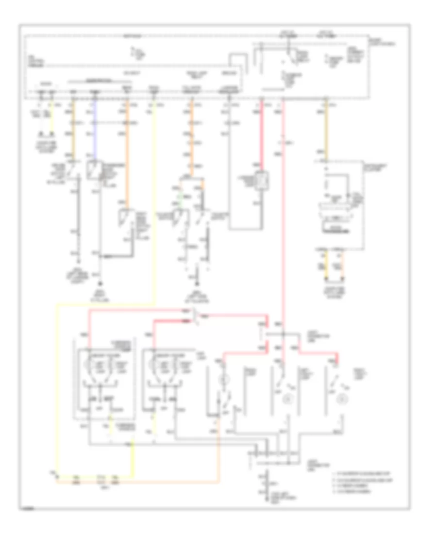
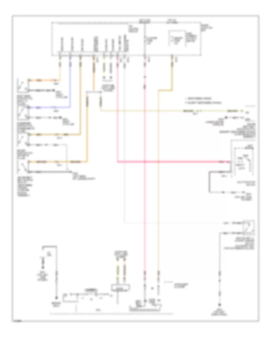
Backup Lamps Wiring Diagram for Hyundai Veloster Turbo 2014
List of elements for Backup Lamps Wiring Diagram for Hyundai Veloster Turbo 2014:
- (not used)
- A/t w/ dual clutch
- A/t w/o dual clutch
- A/v & navigation head unit
- B/up lamp 1 fuse 15a
- B/up lamp 2 fuse 10a
- Backup lamp
- Backup lamp switch (top of transaxle)
- Eggd-tb
- Eggt-aa
- Gf03 (left rear of luggage compt)
- Gf04 (right "c" pillar)
- Hot in on or start
- I/p-b
- I/p-h
- I/p-k
- I/p-m
- Ips control module
- Left rear combination lamp
- M/t
- M02-b
- Mf11
- Mr11
- Mts module (below right side of dash)
- Nca
- On/start
- On/start input
- Pcm (left rear of engine compt)
- R switch
- Red
- Right rear combination lamp
- Smart junction box
- Tcm (lower left end of dash)
- Tcu fuse 10a
- Transaxle range switch (top of transaxle)
- Transaxle range switch signal
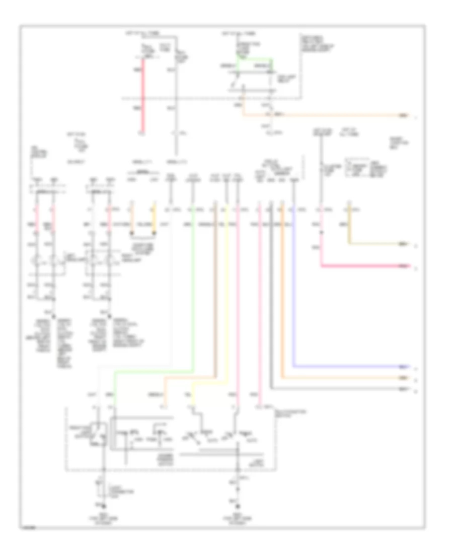
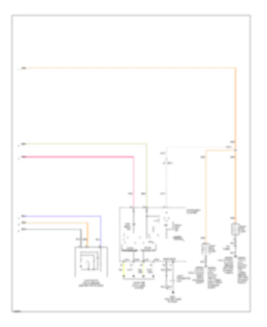
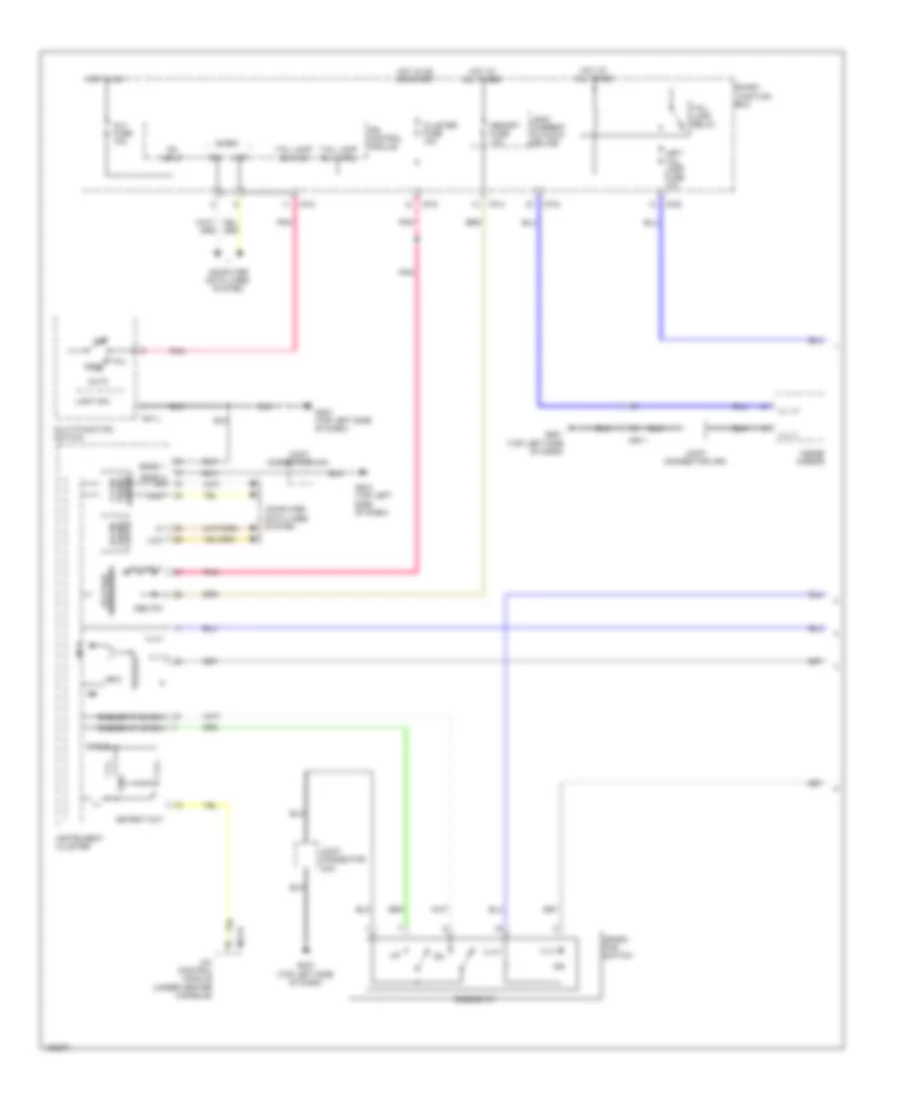
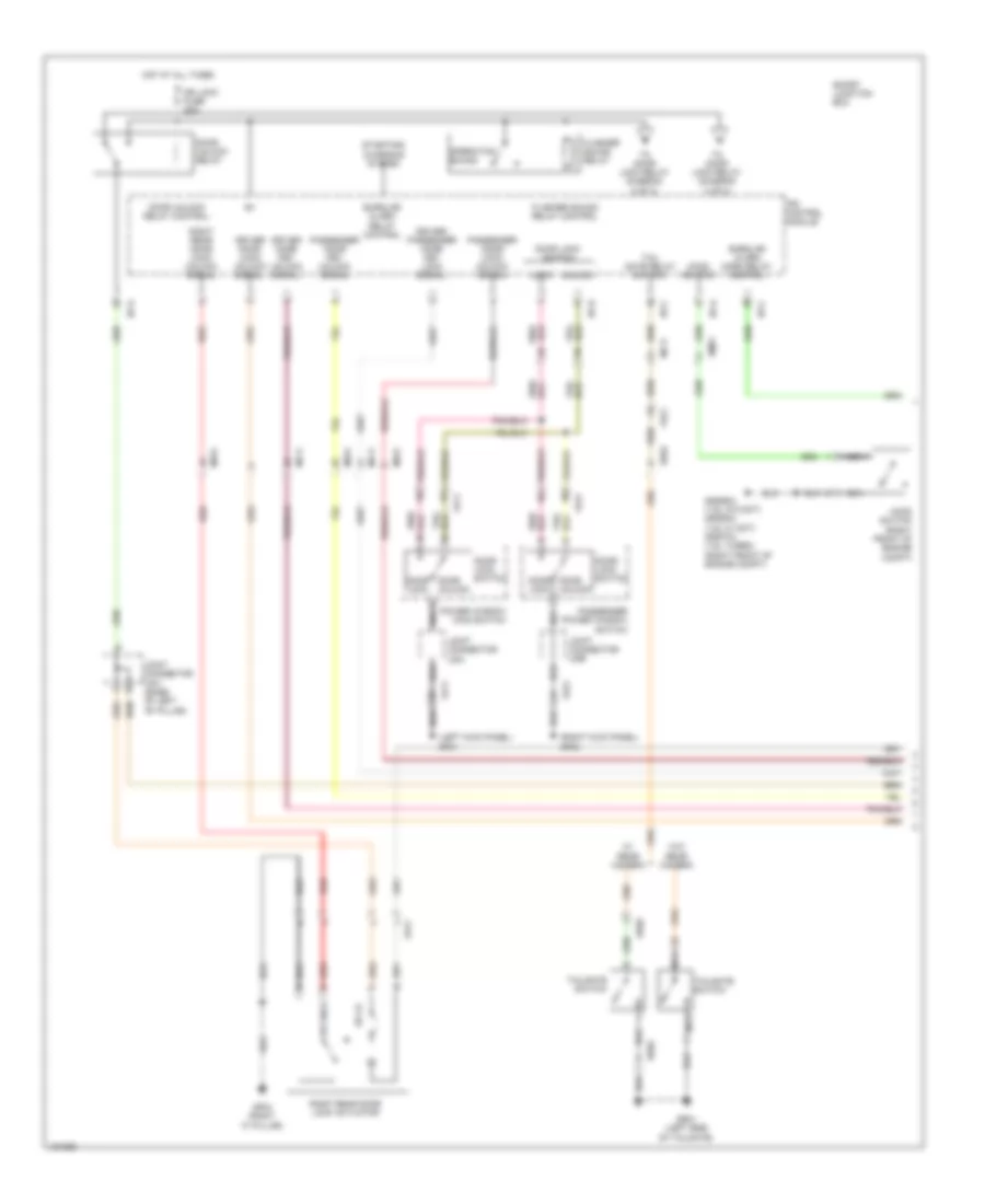
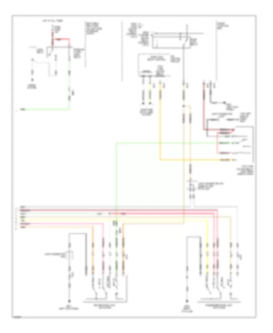
Exterior Lamps Wiring Diagram (1 of 2) for Hyundai Veloster Turbo 2014
List of elements for Exterior Lamps Wiring Diagram (1 of 2) for Hyundai Veloster Turbo 2014:
- (left side of dash) stop signal relay
- (top left side of dash) gm02
- (top of brake pedal assembly) stop lamp switch
- 1.6l turbo
- 1.6l turbo a/t
- 1.6l turbo m/t
- 1.6l w/ dual clutch
- 1.6l w/o dual clutch
- 1.6l w/o dual clutch &
- Abs fuse 10a
- B-can transceiver
- Brake lt
- Brake switch
- Brake test sw
- Brk lt sw
- Brk sw
- C-can transceiver
- Circuit
- Computer data lines system
- E/r fuse & relay box (on left side of engine compt)
- Ecm (1.6l & 1.6l turbo m/t) pcm (1.6l & 1.6l turbo a/t) (left rear of engine compt)
- Ecu fuse 10a
- Eggd-ma
- Eggd-tb
- Eggg-ma
- Eggt-aa
- Eggt-ak
- Eggt-ma
- Em11
- Esc module (right rear of engine compt)
- Fr21
- Gf03 (left rear of luggage compt)
- Gggg01 (1.6l w/o dual clutch) gggd01 (1.6l w/ dual clutch) gggt01 (1.6l turbo) (behind left end of front fascia)
- Gggg04 (1.6l w/o dual clutch) gggd04 (1.6l w/ dual clutch) gggt04 (1.6l turbo) (right front of engine compt)
- Gm01 (top left side of dash)
- Green dimming
- Hac relay
- Hac relay control
- Hac relay rsm
- High
- High-mounted stop lamp
- Hot at all times
- Hot in on or start
- Hot w/ engine control relay on
- I/p-a
- I/p-f
- I/p-h
- I/p-k
- I/p-m
- I/p-n
- Instrument cluster
- Interface
- Ips control module
- Joint connector ued
- Joint connector uma
- Joint connector umb
- Leak current autocut device
- Left headlamp
- Left turn ind
- Low
- M13-b
- Mcu
- Memory fuse 10a
- Nca
- On/start input
- Parking lamp
- Pnk
- Red
- Right headlamp
- Right turn ind
- Sensor fuse 15a
- Sgnd 1
- Sgnd 2
- Side marker lamp
- Smart junction box
- Smart key control module (center of dash)
- Stop lp fuse 15a
- Tail on lamp
- Tcm (w/ dual clutch) (lower left end of dash)
- Turn lamp
- W/ hac
- W/o hac
Exterior Lamps Wiring Diagram (2 of 2) for Hyundai Veloster Turbo 2014
List of elements for Exterior Lamps Wiring Diagram (2 of 2) for Hyundai Veloster Turbo 2014:
- A/c control module (under center console)
- Adc
- Arisu lt 1
- Arisu lt 2
- B-can
- Computer data lines system
- Driver power outside mirror
- Fd11
- Fd21
- Fr11
- Gf01 (left kick panel)
- Gf02 (right kick panel)
- Gf03 (left rear of luggage compt)
- Gf04 (right "c" pillar)
- Gm01 (top left side of dash)
- Gm02 (top left side of dash)
- Ground m21-b
- Hazard lamp sw sig
- Hazard switch
- Head
- High
- Hot at all times
- Hot in on
- I/p-c
- I/p-k
- I/p-m
- I/p-n
- Ig 2 fuse 10a
- Ill
- Interior lights system
- Ips control module
- Joint connector uda
- Joint connector udb
- Joint connector uea
- Joint connector ueb
- Joint connector uma
- Joint connector umb
- Left
- Left license lamp
- Left rear combination lamp
- Left tail lamp fuse 10a
- Light switch
- Low
- M01-l
- Multi-function switch
- Nca
- Off
- On input
- Passenger power outside mirror
- Pnk
- Pwm
- Red
- Right
- Right license lamp
- Right rear combination lamp
- Right tail lamp fuse 10a
- Smart junction box
- Stop lamp
- Tail auto
- Tail lamp
- Tail lamp relay
- Tail lamp sw
- Tail lp rly ctrl
- Turn lamp
- Turn lp sw sig
- Turn signal lamp switch
GROUND DISTRIBUTION
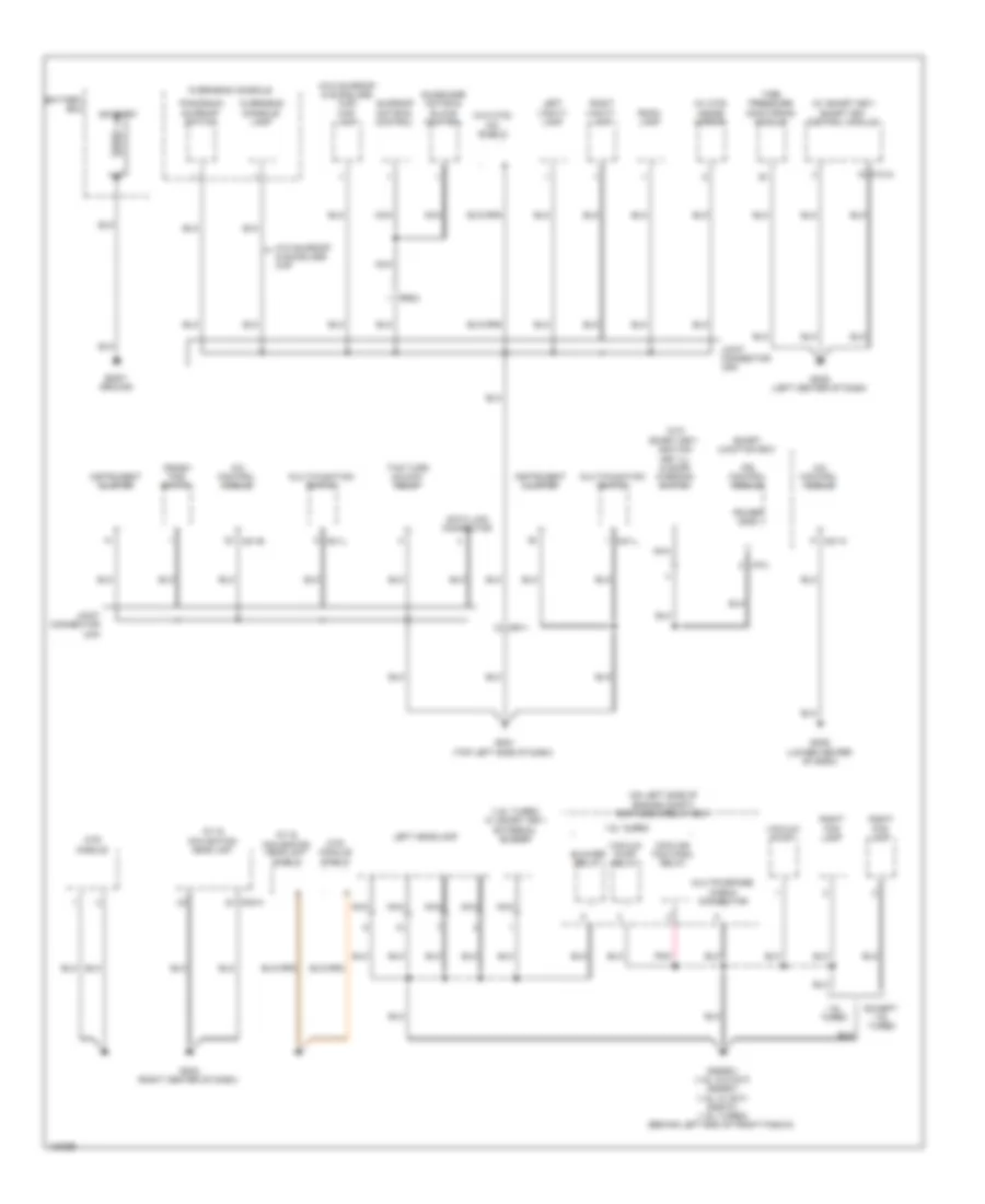
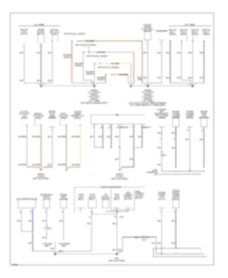
Ground Distribution Wiring Diagram (1 of 4) for Hyundai Veloster Turbo 2014
List of elements for Ground Distribution Wiring Diagram (1 of 4) for Hyundai Veloster Turbo 2014:
- (1.6l turbo w/ smart key) external buzzer
- (on left side of engine compt) e/r fuse & relay box
- (w/ mts) inside mirror
- (w/ smart key) smart key control module
- (w/o mts) mic shield
- (w/o smart key) ignition key ill & door warning switch
- (w/o sunroof & sunglass cap) map lamp
- 1.6l turbo
- A/c control module
- A/v & navigation head unit
- A/v & navigation head unit shield
- Battery
- Battery box
- Blower relay
- Body ground
- Cooling fan (high) relay
- Crash pad switch
- Data link connector
- Except 1.6l turbo
- Gggg01 (1.6l w/o dct) gggd01 (1.6l w/ dct) gggt01 (1.6l turbo) (behind left end of front fascia)
- Gm01 (top left side of dash)
- Gm04 (right center of dash)
- Gm05 (left center of dash)
- Gm06 (lower center of dash)
- I/p-c
- Instrument cluster
- Ips control module
- Joint connector uma
- Joint connector ura
- Left headlamp
- Left vanity lamp
- M01-l
- M02-a
- M13-a
- M21-a
- M21-b
- Mr11
- Mts module
- Mts module shield
- Multi-function switch
- Multipurpose check connector
- Nca
- Overhead console
- Overhead console lamp
- Panorama sunroof switch
- Pnk
- Power (gnd)
- Right fog lamp
- Right vanity lamp
- Room lamp
- Rr03
- Smart junction box
- Sunroof motor & control
- Sunshade motor & slave control
- Tire pressure monitoring module
- Two turn unlock relay
- Vacuum pump
- Vacuum pump relay
- W/o sunroof & sunglass cap
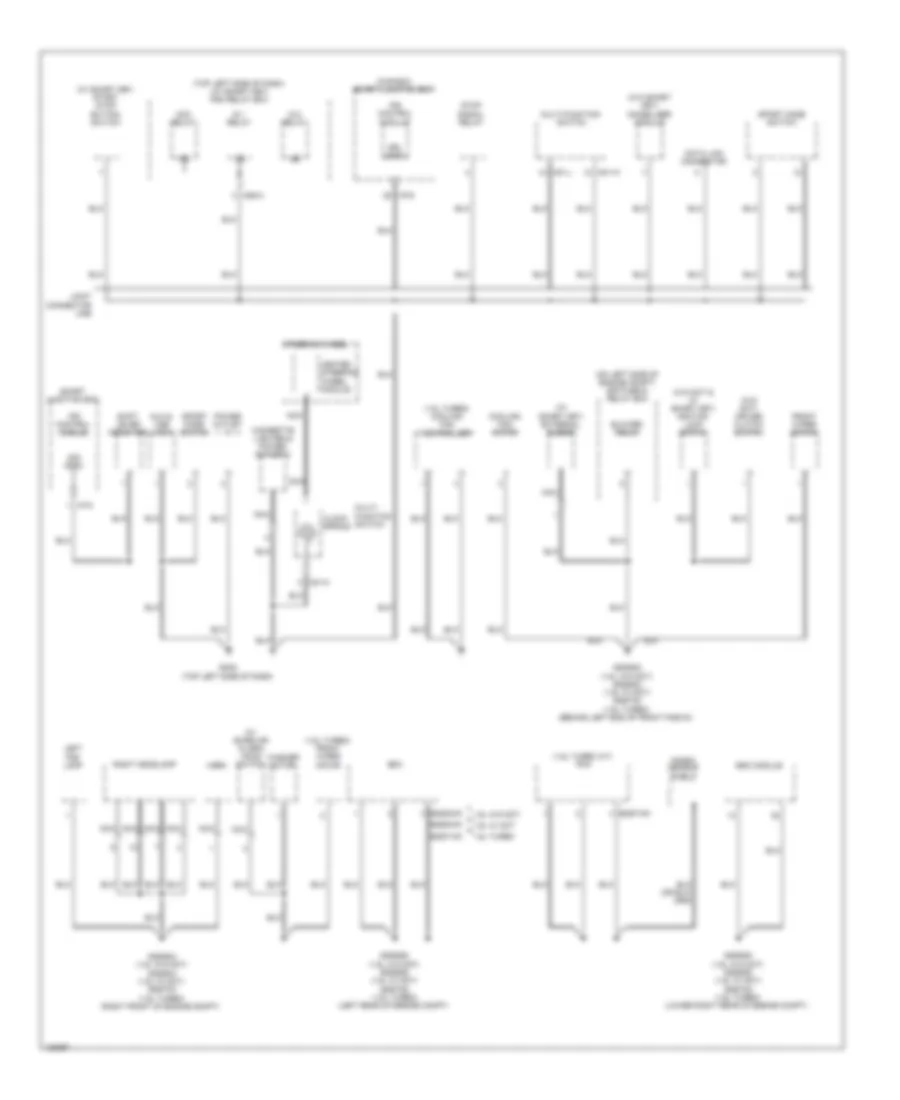
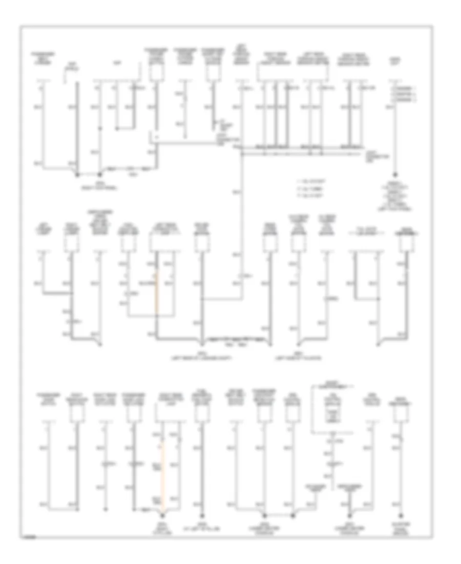
Ground Distribution Wiring Diagram (2 of 4) for Hyundai Veloster Turbo 2014
List of elements for Ground Distribution Wiring Diagram (2 of 4) for Hyundai Veloster Turbo 2014:
- (1.6l turbo a/t) pcm
- (1.6l turbo) cooling fan controller
- (1.6l turbo) front wiper motor
- (canada) smart junction box
- (on left side of engine compt) e/r fuse & relay box
- (top left side of dash) (w/ smart key) pdm relay box
- (w/ burglar alarm) hood switch
- (w/ smart key) external buzzer
- (w/ smart key) start stop button switch
- (w/o dct & w/ smart key) ignition lock switch
- (w/o dct) cruise clutch switch
- (w/o smart key) immobilizer module
- 1.6l turbo
- 1.6l w/ dct
- 1.6l w/o dct
- Acc relay
- Aux & usb jack
- Blower relay
- Cigarette lighter & power outlet 2
- Clock spring
- Cooling fan motor
- Data link connector
- Drl (gnd)
- Ecm
- Eggd-mk
- Eggg-mk
- Eggt-ak
- Eggt-mk
- Esc module
- Front wiper motor
- Gggg02 (1.6l w/o dct) gggd02 (1.6l w/ dct) gggt02 (1.6l turbo) (behind left end of front fascia)
- Gggg04 (1.6l w/o dct) gggd04 (1.6l w/ dct) gggt04 (1.6l turbo) (right front of engine compt)
- Gggg06 (1.6l w/o dct) gggd06 (1.6l w/ dct) gggt06 (1.6l turbo) (left rear of engine compt)
- Gggg08 (1.6l w/o dct) gggd08 (1.6l w/ dct) gggt08 (1.6l turbo) (lower right rear of engine compt)
- Gm02 (top left side of dash)
- Heated steering wheel module
- Horn
- I/p-c
- I/p-d
- Ig 1 relay
- Ig 2 relay
- Ips control module
- Joint connector umb
- Knock sensor shield
- Left fog lamp
- M01-l
- M01-m
- M01-w
- M06-a
- Multi- function switch
- Multi-function switch
- Nca
- Power outlet
- Right headlamp
- Shift lever indicator
- Sig (gnd)
- Smart junction box
- Sport mode switch
- Steering wheel
- Stop signal relay
- Washer motor
Ground Distribution Wiring Diagram (3 of 4) for Hyundai Veloster Turbo 2014
List of elements for Ground Distribution Wiring Diagram (3 of 4) for Hyundai Veloster Turbo 2014:
- (left kick panel)
- (w/ dct) (left kick panel)
- (w/ smart key) driver smart key outside handle
- (w/o dct) brake fluid level sensor
- 1.6l turbo
- A/c inverter module
- Brake fluid level sensor
- Clutch actuator 1 & 2 shield
- Clutch speed sensor 1 & 2 shield
- Condenser
- Cruise clutch switch
- Dd11
- Door lock relay
- Door unlock relay
- Driver door lock actuator
- Driver power outside mirror
- Driver safety power window module
- Driver seat manual switch
- Driver seat warmer
- Eggd-ta
- Eggd-tb
- Fd11
- Fs12
- Gf01
- Gggd12
- Gggd13 (w/ dct) (left kick panel)
- Gggg07 (1.6l w/o dct) gggd07 (1.6l w/ dct) gggt07 (1.6l turbo) (left rear of engine compt)
- Gggg09 (1.6l w/o dct) gggd09 (1.6l w/ dct) gggt09 (1.6l turbo) (1.6l w/ dct & w/o dct: rear of engine) (1.6l turbo: rear of cylinder head)
- I/p-k
- Ignition coil 1 shield
- Ignition coil 1,2,3,4 shield
- Ignition coil 2 shield
- Ignition coil 3 shield
- Ignition coil 4 shield
- Ignition lock switch
- Ips control module
- Joint connector uda
- Leak current autocut device
- Leak current autocut switch
- Nca
- Power outside mirror switch
- Power window main switch
- Room lamp relay
- Select actuator shield
- Shift actuator shield
- Smart junction box
- Tcm
- W/ power seat
- W/o power seat
Ground Distribution Wiring Diagram (4 of 4) for Hyundai Veloster Turbo 2014
List of elements for Ground Distribution Wiring Diagram (4 of 4) for Hyundai Veloster Turbo 2014:
- (at left "b" pillar)
- (depowered a/bag) driver seat belt buckle switch
- (left rear of luggage compt)
- (left side of tailgate)
- (right "c" pillar)
- (right kick panel)
- (w/ rear camera) tail gate switch
- (w/o rear camera) tail gate switch
- 1.6l turbo
- 1.6l w/ dct
- 1.6l w/o dct
- Advanced a/bag
- Amp
- Amp shield
- Depowered a/bag
- Driver door switch
- Driver seat belt buckle switch
- Eggd66
- Eggg66
- Eggt66
- F02-a
- Fd21
- Fd41
- Fr11
- Fr21
- Fuel sender & fuel pump motor
- Gf02
- Gf03
- Gf04
- Gf05 (under center console)
- Gf06
- Gf07 (under center console)
- Gggg11 (1.6l w/o dct) gggd11 (1.6l w/ dct) gggt11 (1.6l turbo) (left kick panel)
- Gr01
- High- mounted stop lamp
- I/p-b
- Ips control module
- Joint connector udb
- Joint connector urc
- Left license lamp
- Left rear combination lamp
- Left rear parking assist sensor
- Left rear parking assist sensor center
- Mdps unit
- Mf11
- Nca
- Panel ground
- Passenger door lock actuator
- Passenger door switch
- Passenger occupant detection sensor
- Passenger power outside mirror
- Passenger power window switch
- Passenger seat warmer
- Passenger smart key outside handle
- Quarter
- R21-cl
- R21-cr
- R21-l
- R21-r
- Rear defogger 1
- Rear defogger 2
- Rear wiper motor
- Right license lamp
- Right rear combination lamp
- Right rear door lock actuator
- Right rear door switch
- Right rear parking assist sensor
- Right rear parking assist sensor center
- Rr01
- Rr02
- Side air bag
- Smart junction box
- Srs control module
- Tail gate lid latch
- W/ smart key
HEADLIGHTS
Autolamps Wiring Diagram (1 of 2) for Hyundai Veloster Turbo 2014
List of elements for Autolamps Wiring Diagram (1 of 2) for Hyundai Veloster Turbo 2014:
- Adc
- Arisu lt 1
- Arisu lt 2
- Auto
- Auto light sensor
- Auto light sw
- B+2 fuse 50a
- B+3 fuse 50a
- B-can
- Cluster fuse 10a
- Computer data lines system
- Dimmer/ passing switch
- E/r fuse & relay box (on left side of engine compt)
- Em11
- Fog lamp relay
- Fog lp rly ctrl
- Fog lp sw
- Front fog lamp fuse 10a
- Front fog lamp switch
- Gggd01 (1.6l w/ dual clutch) gggt01 (1.6l turbo) (behind left end of front fascia)
- Gggd04 (1.6l w/ dual clutch) gggt04 (1.6l turbo) (right front of engine compt)
- Gggg01 (1.6l w/o dual clutch) (behind left end of front fascia)
- Gggg04 (1.6l w/o dual clutch) (right front of engine compt)
- Gm01 (top left side of dash)
- Gnd
- H/lp hi sw
- H/lp low sig
- H/lp sw
- Head
- High
- Hot at all times
- Hot in on
- Hot in on or start
- I/p-a
- I/p-c
- I/p-d
- I/p-g
- I/p-h
- I/p-l
- I/p-m
- Ig 2 fuse 10a
- Ips control module
- Joint connector uma
- Leak current autocut device
- Left headlamp
- Light switch
- Low
- Low pass
- M01-l
- Memory fuse 10a
- Multi fuse
- Multi-function switch
- Nca
- Off
- On input
- Pass
- Pnk
- Pwm
- Pwr
- Red
- Right headlamp
- Sig
- Smart junction box
- Tail
- Tail lp sw
Autolamps Wiring Diagram (2 of 2) for Hyundai Veloster Turbo 2014
List of elements for Autolamps Wiring Diagram (2 of 2) for Hyundai Veloster Turbo 2014:
- 1.6l turbo
- Autolight & photo sensor (center top of dash)
- B-can transceiver
- C-can transceiver
- Computer data lines
- Em11
- Front fog ind
- Gggd01 (1.6l w/ dual clutch) gggt01 (1.6l turbo) (behind left end of front fascia)
- Gggd04 (1.6l w/ dual clutch) gggt04 (1.6l turbo) (right front of engine compt)
- Gggg01 (1.6l w/o dual clutch) (behind left end of front fascia)
- Gggg04 (1.6l w/o dual clutch) (right front of engine compt)
- Gm01 (top left side of dash)
- Green dimming
- High
- High beam ind
- Instrument cluster
- Joint connector uma
- Left fog lamp
- Low
- Mcu
- Pnk
- Right fog lamp
- Sgnd
- System
Headlamps Wiring Diagram for Hyundai Veloster Turbo 2014
List of elements for Headlamps Wiring Diagram for Hyundai Veloster Turbo 2014:
- 1.6l turbo
- Adc
- Arisu lt 1
- Arisu lt 2
- Auto
- B+2 fuse 50a
- B+3 fuse 50a
- B-can
- B-can transceiver
- C-can transceiver
- Cluster fuse 10a
- Computer data lines system
- Dimmer/ passing switch
- E/r fuse & relay box (on left side of engine compt)
- Em11
- Fog lamp relay
- Fog lp rly ctrl
- Fog lp sw
- Front fog ind
- Front fog lamp fuse 10a
- Front fog lamp switch
- Gggd01 (1.6l w/ dual clutch) gggg01 (1.6l w/o dual clutch) gggt01 (1.6l turbo) (behind left end of front fascia)
- Gggd01 (1.6l w/ dual clutch) gggt01 (1.6l turbo) gggg01 (1.6l w/o dual clutch) (behind left end of front fascia)
- Gggd04 (1.6l w/ dual clutch) gggg04 (1.6l w/o dual clutch) gggt04 (1.6l turbo) (right front of engine compt)
- Gggd04 (1.6l w/ dual clutch) gggt04 (1.6l turbo) gggg04 (1.6l w/o dual clutch) (right front of engine compt)
- Gm01 (top left side of dash)
- Green dimming
- H/lp hi sw
- H/lp low sig
- H/lp sw
- Head
- High
- High beam ind
- Hot at all times
- Hot in on
- Hot in on or start
- I/p-a
- I/p-c
- I/p-d
- I/p-g
- I/p-h
- I/p-l
- I/p-m
- Ig 2 fuse 10a
- Instrument cluster
- Ips control module
- Joint connector uma
- Leak current autocut device
- Left fog lamp
- Left headlamp
- Light switch
- Low
- Low pass
- M01-l
- Mcu
- Memory fuse 10a
- Multi fuse
- Multi-function switch
- Nca
- Off
- On input
- Pass
- Pnk
- Pwm
- Red
- Right fog lamp
- Right headlamp
- Sgnd
- Smart junction box
- Tail
- Tail lp sw
HORN
Horn Wiring Diagram for Hyundai Veloster Turbo 2014
List of elements for Horn Wiring Diagram for Hyundai Veloster Turbo 2014:
- Burglar alarm horn relay
- Burglar alarm horn relay ctrl
- Clock spring
- E/r relay & fuse box (on left side of engine compt)
- Em11
- Gggg04 (1.6l w/o dual clutch) gggd04 (1.6l w/ dual clutch) gggt04 (1.6l turbo) (right front of engine compt)
- Horn (behind right side of front fascia)
- Horn fuse 15a
- Horn relay
- Horn switch
- Hot at all times
- I/p-c
- Ips control module
- M01-h
- M01-r
- Multi-function switch
- Nca
- Red
- Smart junction box
- Steering wheel
- W/ heated steering wheel w/o heated steering wheel
INSTRUMENT CLUSTER
Instrument Cluster Wiring Diagram, with Conventional Cluster (1 of 2) for Hyundai Veloster Turbo 2014
List of elements for Instrument Cluster Wiring Diagram, with Conventional Cluster (1 of 2) for Hyundai Veloster Turbo 2014:
- (+)
- (-)
- 4p output
- A/v & navigation head unit
- Abs ind
- Acc/on input
- Active eco input
- Air bag ind
- Anti-theft system
- Audio fuse 10a
- B-can
- Bag air
- Brake ind
- Buzzer
- C-can
- Charge
- Charge ind
- Check engine ind
- Clock
- Cluster fuse 10a
- Computer data lines system
- Cruise control system
- Cruise ind
- Cruise set ind
- Dail ill
- Detent out
- Door open ind
- Driver
- Eco (green) ind
- Eeprom
- Eps ind
- Esc ind
- Esc off ind
- Fog front
- Front fog ind
- Fuel (+)
- Fuel (-)
- Fuel cap open ind
- Gm01 (top left side of dash)
- Gm04 (right center of dash)
- Green dimming
- Ground
- Headlights system
- Heated steer input
- High
- High beam ind
- Hot at all times
- Hot in acc or on
- Hot in on or start
- I/p-e
- I/p-g
- I/p-h
- Ill (+)
- Ill (-)
- Immo
- Immo ind
- Instrument cluster
- Interior lights system
- J/c uma
- Key out ind
- Lcd
- Lcd ill
- Leak current autocut device
- Left turn ind
- Low
- Low fuel ind
- M02-a
- M02-b
- Mcu
- Memory fuse 10a
- Memory power
- Multi media fuse 15a
- Odo
- Oil pressure
- Oil pressure ind
- On/start input
- Out d
- Out n
- Out p
- Out r
- P position
- P/brake
- Pnk
- Pointer ill
- Red
- Rheostat down
- Rheostat up
- Right turn ind
- Seat belt ind
- Seats system
- Sensor gnd 1
- Sensor gnd 2
- Smart junction box
- Speedo- meter
- Starting/charging system
- Tacho- meter
- Tail gate open ind
- Tail on ind
- Temp high ind
- Tpms tread ind
- Transceiver
- Transmissions system
- Trip (+)
- Trip (-)
- Vehicle sp sig
- Voltage regulator
Instrument Cluster Wiring Diagram, with Conventional Cluster (2 of 2) for Hyundai Veloster Turbo 2014
List of elements for Instrument Cluster Wiring Diagram, with Conventional Cluster (2 of 2) for Hyundai Veloster Turbo 2014:
- (+)
- (-)
- (left side of tail gate) gr01
- (right front of engine compt) (1.6l w/o dual clutch) gggg04
- (w/ heated steering wheel)
- (w/o heated steering wheel)
- 1.6l turbo
- 1.6l turbo a/t
- 1.6l turbo m/t
- 1.6l w/ dct
- 1.6l w/o dct
- B-can
- Brake fluid level sensor (on brake fluid reservoir)
- Cancel
- Clock spring
- Computer data lines system
- Crash pad switch
- Door switch
- Dri
- Driver door switch (driver "b" pillar)
- Ecm (m/t) pcm (a/t) (left rear of engine compt)
- Eco switch
- Ecs module (right rear of engine compt)
- Ee31
- Ef11
- Eggd-mk
- Eggd-tb
- Eggg-mk
- Eggt-aa
- Eggt-mk
- Em11
- Empty
- Fr21
- Fuel level float
- Fuel sender
- Fuel sender & fuel pump motor (top center of fuel tank)
- Full
- Gf03 (left rear of luggage compt)
- Gf04 (right "c" pillar)
- Gggt04 (1.6l turbo) gggd13 (1.6l w/ dual clutch) (1.6l turbo: right front of engine compt) (1.6l w/ dual clutch: left kick panel)
- Gm01 (top left side of dash)
- High
- Hot in on
- I/p-b
- I/p-c
- I/p-g
- Ig 2 fuse 10a
- Ill
- Ind
- Interior lights system
- Ips control module
- J/c uma
- Low
- M01-h
- M01-r
- Mf11
- Mf61
- Multi-function switch
- Nca
- Oil pressure switch (near oil filter)
- On/ off
- Parking brake switch (base of parking brake lever assembly)
- Pass
- Passenger door switch (passenger "b" pillar)
- Pnk
- Rear rh
- Res (+)
- Reset
- Right cruise remote control switch
- Right rear door switch (right rear "c" pillar)
- Right trip remote control switch
- Rr01
- Rr02
- Set (-)
- Smart junction box
- Steering wheel
- Tail gate relay sw
- Tail gate switch
- Tcm (1.6l w/ dual clutch) (lower left end of dash)
- Trip
- Trip (sig in)
- Trip (sig out)
- Trip(+)
- Trip(-)
- W/ rear camera
- W/o rear camera
Instrument Cluster Wiring Diagram, with Super Vision (1 of 2) for Hyundai Veloster Turbo 2014
List of elements for Instrument Cluster Wiring Diagram, with Super Vision (1 of 2) for Hyundai Veloster Turbo 2014:
- (+)
- (-)
- 4p output
- A/v & navigation head unit
- Abs ind
- Acc/on input
- Active eco input
- Air bag ind
- Anti-theft system
- Audio fuse 10a
- B-can
- Bag air
- Brake ind
- Buzzer
- C-can
- Charge
- Charge ind
- Check engine ind
- Clock
- Cluster fuse 10a
- Computer data lines system
- Constant current
- Cruise control system
- Cruise ind
- Cruise set ind
- Detent out
- Dial ill
- Door open ind
- Driver
- Eco (green) ind
- Eeprom
- Eps ind
- Esc ind
- Esc off ind
- Fog front
- Front fog ind
- Fuel (+)
- Fuel (-)
- Fuel cap open
- Gm01 (top left side of dash)
- Gm04 (right center of dash)
- Green dimming
- Ground
- Headlights system
- Heating steer input
- High
- High beam ind
- Hot at all times
- Hot in acc or on
- Hot in on or start
- I/p-e
- I/p-g
- I/p-h
- Ill (+)
- Ill (-)
- Immo
- Immo ind
- Instrument cluster
- Interior lights system
- J/c uma
- Key out ind
- Lcd
- Leak current autocut device
- Left turn ind
- Low
- Low fuel ind
- M02-a
- M02-b
- Mcu
- Memory fuse 10a
- Memory power
- Multi media fuse 15a
- Odo
- Oil pressure
- Oil pressure ind
- On/start input
- Out d
- Out n
- Out p
- Out r
- P position
- P/brake
- Pnk
- Pointer ill
- Red
- Rheostat down
- Rheostat up
- Right turn ind
- Seat belt ind
- Seats system
- Sensor gnd 1
- Sensor gnd 2
- Smart junction box
- Speedo- meter
- Starting/charging system
- Tacho- meter
- Tail gate open ind
- Tail on ind
- Temp high ind
- Tpms tread ind
- Transceiver
- Transmissions system
- Trip (+)
- Trip (-)
- Vehicle sp sig
- Voltage regulator 1
- Voltage regulator 2
Instrument Cluster Wiring Diagram, with Super Vision (2 of 2) for Hyundai Veloster Turbo 2014
List of elements for Instrument Cluster Wiring Diagram, with Super Vision (2 of 2) for Hyundai Veloster Turbo 2014:
- (+)
- (-)
- (left side of tail gate) gr01
- (right front of engine compt) (1.6l w/o dual clutch) gggg04
- (w/ heated steering wheel)
- (w/o heated steering wheel)
- 1.6l turbo
- 1.6l turbo a/t
- 1.6l turbo m/t
- 1.6l w/ dct
- 1.6l w/o dct
- B-can
- Brake fluid level sensor (on brake fluid reservoir)
- Cancel
- Clock spring
- Computer data lines system
- Crash pad switch
- Door switch
- Dri
- Driver door switch (driver "b" pillar)
- Ecm (m/t) pcm (a/t) (left rear of engine compt)
- Eco switch
- Ecs module (right rear of engine compt)
- Ee31
- Ef11
- Eggd-mk
- Eggd-tb
- Eggg-mk
- Eggt-aa
- Eggt-mk
- Em11
- Empty
- Fr21
- Fuel level float
- Fuel sender
- Fuel sender & fuel pump motor (top center of fuel tank)
- Full
- Gf03 (left rear of luggage compt)
- Gf04 (right "c" pillar)
- Gggt04 (1.6l turbo) gggd13 (1.6l w/ dual clutch) (1.6l turbo: right front of engine compt) (1.6l w/ dual clutch: left kick panel)
- Gm01 (top left side of dash)
- High
- Hot in on
- I/p-b
- I/p-c
- I/p-g
- Ig 2 fuse 10a
- Ill
- Ind
- Interior lights system
- Ips control module
- J/c uma
- Low
- M01-h
- M01-r
- Mf11
- Mf61
- Multi-function switch
- Nca
- Oil pressure switch (near oil filter)
- On/ off
- Parking brake switch (base of parking brake lever assembly)
- Pass
- Passenger door switch (passenger "b" pillar)
- Pnk
- Rear rh
- Res (+)
- Reset
- Right cruise remote control switch
- Right rear door switch (right rear "c" pillar)
- Right trip remote control switch
- Rr01
- Rr02
- Set (-)
- Smart junction box
- Steering wheel
- Tail gate relay sw
- Tail gate switch
- Tcm (1.6l w/ dual clutch) (lower left end of dash)
- Trip
- Trip (sig in)
- Trip (sig out)
- Trip(+)
- Trip(-)
- W/ rear camera
- W/o rear camera
INTERIOR LIGHTS
Courtesy Lamps Wiring Diagram for Hyundai Veloster Turbo 2014
List of elements for Courtesy Lamps Wiring Diagram for Hyundai Veloster Turbo 2014:
- "b" pillar)
- "c" pillar)
- (top left side of dash) gm01
- Autocut device
- B-can
- B-can transceiver
- Computer data lines system
- Door
- Door ind
- Door switch
- Dri
- Driver door switch (left
- Gf03 (left rear of luggage compt)
- Gf04 (right
- Gnd
- Gr01 (left side
- Ground
- High
- Hot at all times
- Hot in on
- I/p-b
- I/p-c
- I/p-d
- I/p-h
- I/p-k
- Ig 2 fuse 10a
- Instrument cluster
- Interior lamp fuse 10a
- Ips control module
- Joint connector ura
- Joint connector urb
- Leak current
- Left map lamp
- Left vanity lamp
- Low
- Luggage room lamp
- Map lamp
- Mcu
- Memory fuse 10a
- Memory power
- Mf11
- Mf21
- Mf61
- Mr11
- Nca
- Of tailgate)
- Off
- On input
- Overhead console
- Overhead console lamp
- Pass
- Passenger door switch (right "b" pillar)
- Rear rh
- Red
- Right map lamp
- Right rear door switch (right "c" pillar)
- Right vanity lamp
- Room lamp
- Room lamp relay
- Rr01
- Rr02
- Smart junction box
- Tail gate open ind
- Tail gate open sw
- Tailgate switch
- W/ rear camera
- W/ sunroof & sunglass cap
- W/o rear camera
- W/o sunroof & sunglass cap
Instrument Illumination Wiring Diagram (1 of 2) for Hyundai Veloster Turbo 2014
List of elements for Instrument Illumination Wiring Diagram (1 of 2) for Hyundai Veloster Turbo 2014:
- A/c control module (under center console)
- Auto
- B-can
- Bat d
- C-can
- Cluster fuse 10a
- Computer data lines
- Computer data lines system
- Crash pad switch
- Detent out
- Gm01 (top left side of dash)
- Head
- High
- Hot at all times
- Hot in on
- Hot in on or start
- I/p-c
- I/p-e
- I/p-g
- I/p-h
- Ig 2 fuse 10a
- Ill (+)
- Ill (-)
- Ill(+)
- Ill(-)
- Inside mirror
- Instrument cluster
- Ips control module
- Joint connector uma
- Joint connector ura
- Leak current autocut device
- Left
- Light sw
- Low
- M01-l
- M21-b
- Mcu
- Mem pw
- Memory fuse 10a
- Mr11
- Multi-function switch
- Off
- On input
- Pnk
- Rheostat
- Rheostat dn sw
- Rheostat up sw
- Sgnd 1
- Sgnd 2 hi
- Smart junction box
- System
- Tail
- Tail lamp fuse 10a
- Tail lamp relay
- Tail lamp rly ctrl
- Tail lamp switch
- Trans- ceiver
- Voltage regulator
Instrument Illumination Wiring Diagram (2 of 2) for Hyundai Veloster Turbo 2014
List of elements for Instrument Illumination Wiring Diagram (2 of 2) for Hyundai Veloster Turbo 2014:
- (lower left center of dash) joint connector jm04
- A/c control module (under center m21-b console)
- A/v & navigation head unit
- Aux & usb jack
- B-can high
- B-can low
- Clock spring
- Computer data lines system
- Driver seat warmer switch
- Esc off switch
- Fd11
- Fd21
- Gf01 (left kick panel)
- Gf02 (right kick panel)
- Gm02 (top left side of dash)
- Joint connector jm04 (lower left center of dash)
- Joint connector uda
- Joint connector udb
- M01-h
- M01-r
- M02-a
- M13-a
- M13-c
- M21-b
- Mf11
- Mf61
- Multi- function switch
- Nca
- Passenger power window switch
- Passenger seat warmer switch
- Power window main switch
- Right cruise remote control switch
- Right trip remote control switch
- Shift lever indicator
- Smart key control module (center of dash)
- Ssb ill gnd
- Ssb ill power
- Start stop button switch
- Steering wheel
- W/ heated steering wheel
- W/ smart key
- W/o heated steering wheel
NAVIGATION
Mobile Telematic System Wiring Diagram for Hyundai Veloster Turbo 2014
List of elements for Mobile Telematic System Wiring Diagram for Hyundai Veloster Turbo 2014:
- (below right
- (right center
- A/bag
- A/v & navigation head unit
- Acc/on in
- Audio
- Audio (+)
- Audio (-)
- Audio out (+)
- Audio out (-)
- Bcm rx
- Bcm tx
- C-can hi
- C-can lo
- Cluster fuse 10a
- Computer
- Computer data lines system
- Crash
- Crash in
- Data lines
- Exterior lights system
- Fuse 10a
- Gm01 (top left
- Gm01 (top left side of dash)
- Gm04
- Gnd
- Hot at all times
- Hot in acc or on
- Hot in on or start
- I/p-c
- I/p-e
- I/p-g
- Ig 1
- Ill (+)
- Ill (-)
- Inside mirror
- Ips control module
- Joint connector ura
- Keypad gnd
- Keypad in
- L mts rx
- Leak current autocut device
- M-can hi
- M-can lo
- M02-a
- M02-m
- M51
- Mem power
- Mic (+)
- Mic (-)
- Mic (left front of roof)
- Mic in (+)
- Mic in (-)
- Mic out (+)
- Mic out (-)
- Mic shield
- Mr11
- Mts module
- Multi media fuse 15a
- Nca
- O mts tx
- Of dash)
- On/start in
- Red
- Reverse sig
- Rx (+)
- Rx (-)
- Shield gnd
- Side of dash)
- Sig
- Smart junction box
- Srs control module (under floor console)
- System
- Tx (+)
- Tx (-)
- Unlock
Navigation Wiring Diagram, with Amplifier (1 of 3) for Hyundai Veloster Turbo 2014
List of elements for Navigation Wiring Diagram, with Amplifier (1 of 3) for Hyundai Veloster Turbo 2014:
- A/v & navigation head unit
- Acc/on input
- Alt l
- Ambient snsr
- Ambient temperature sensor (behind center of front fascia)
- Audio (+)
- Audio (-)
- Audio fuse 10a
- Auto light
- Aux cusb in
- Aux detect
- Aux l in
- Aux r in
- Aux ref
- Aux v gnd
- B-can high
- B-can low
- Backup lamp sig
- Computer data lines system
- Cruise control system
- Door unlock
- Door unlock switch
- Em61
- Exterior lights system
- Fr21
- Gm04 (right center of dash)
- Ground
- Hot at all times
- Hot in acc or on
- I/p-c
- I/p-d
- I/p-e
- I/p-g
- I/p-k
- Ill (+)
- Ill (-)
- Instrument cluster system
- Interior lights system
- Ips control module
- Leak current autocut device
- M-can high
- M-can low
- M02-a
- M02-b
- M02-m
- Memory power
- Mf11
- Mic(+)
- Mic(-)
- Mobile telematic system circuit
- Multi media fuse 15a
- Navi voice (+)
- Navi voice (-)
- Navigation system
- Nca gnd 2
- Nca power
- Nca v gnd
- Nca v out
- P position
- Pnk
- Rear camera (in outside tailgate handle assembly)
- Rear camera gnd
- Rear camera power
- Rear camera v gnd
- Rear camera v out
- Red
- Remote ctrl sw gnd
- Remote ctrl sw sig
- Rr01
- Rr02
- Rx (+)
- Rx (-)
- Shield gnd
- Smart junction box
- Spdif gnd
- Spdif out (+)
- Spdif out (-)
- Starting/charging system
- Tx (+)
- Tx (-)
- Vehicle speed
Navigation Wiring Diagram, with Amplifier (2 of 3) for Hyundai Veloster Turbo 2014
List of elements for Navigation Wiring Diagram, with Amplifier (2 of 3) for Hyundai Veloster Turbo 2014:
- (+)
- (-)
- (right center of dash) gm04
- 3ea ill
- 4ea ill
- Audio
- Audio (+)
- Audio (-)
- Aux & usb jack
- Aux detect
- Aux l in
- Aux r in
- Aux ref
- Aux shield gnd
- Aux v gnd
- Aux video in
- B/t
- B/t in
- Call
- Clock spring
- Down
- End of
- Gm01 (top left side of dash)
- Gm02 (top left side of dash)
- Gm04 (right center of dash)
- Ground
- Ill (+)
- Interior lights system
- Joint connector
- Left audio remote control switch
- M01-h
- M01-r
- Mf61
- Mic (+)
- Mic (-)
- Mic (left front of roof)
- Mode
- Mr11
- Multi-function switch
- Nca
- Out
- Red
- Seek
- Send
- Steering wheel
- Ura
- Voice
- Vol
- W/ heated steering wheel
- W/o heated steering
- Wheel
Navigation Wiring Diagram, with Amplifier (3 of 3) for Hyundai Veloster Turbo 2014
List of elements for Navigation Wiring Diagram, with Amplifier (3 of 3) for Hyundai Veloster Turbo 2014:
- (+)
- (-)
- (right kick panel) gf02
- Acc/on input
- Amp (under passenger's seat)
- Amp fuse 25a
- Center speaker
- Center speaker (+)
- Center speaker (-)
- Computer data
- Driver door (+)
- Driver door (-)
- Driver door speaker
- Driver door tweeter speaker
- F02-a
- F02-b
- F02-c
- Fd11
- Fd21
- Fd41
- Gf02 (right kick panel)
- Ground
- Hot at all times
- I/p-k
- Left rear quarter speaker
- Lines system
- M-can high
- M-can low
- Memory power
- Mf61
- Navi voice (+)
- Navi voice (-)
- Nca
- Passenger door (+)
- Passenger door (-)
- Passenger door speaker
- Passenger door tweeter speaker
- Pnk
- Right rear door speaker
- Rl(+)
- Rl(-)
- Rr(+)
- Rr(-)
- S/woof wl(+)
- S/woof wl(-)
- S/woof wr(+)
- S/woof wr(-)
- Smart junction box
- Spdif out (+)
- Spdif out (-)
- Woofer speaker
Navigation Wiring Diagram, without Amplifier (1 of 2) for Hyundai Veloster Turbo 2014
List of elements for Navigation Wiring Diagram, without Amplifier (1 of 2) for Hyundai Veloster Turbo 2014:
- A/v & navigation head unit
- Acc/on input
- Alt l
- Ambient sens
- Ambient temperature sensor (behind center of front fascia)
- Audio (+)
- Audio (-)
- Audio fuse 10a
- Auto light
- Aux cusb in
- Aux detect
- Aux l in
- Aux r in
- Aux ref
- Aux v gnd
- B-can high
- B-can low
- Backup lamp sig
- Computer data lines system
- Cruise control system
- Door unlock
- Door unlock switch
- Em61
- Exterior lights system
- Fl(+)
- Fl(-)
- Fr(+)
- Fr(-)
- Fr21
- Gm04 (right center of dash)
- Ground
- Hot at all times
- Hot in acc or on
- I/p-c
- I/p-d
- I/p-e
- I/p-g
- Ill (+)
- Ill (-)
- Instrument cluster system
- Interior lights system
- Ips control module
- Leak current autocut device
- M-can high
- M-can low
- M02-a
- M02-b
- M02-m
- Memory power
- Mf11
- Mic(+)
- Mic(-)
- Mobile telematic system circuit
- Multi media fuse 15a
- Navigation system
- Nca gnd 2
- Nca power
- Nca v gnd
- Nca v out
- P position
- Pnk
- Rear camera (in outside tailgate handle assembly)
- Rear camera gnd
- Rear camera power
- Rear camera v gnd
- Rear camera v out
- Red
- Remote ctrl sw gnd
- Remote ctrl sw sig
- Rl(+)
- Rl(-)
- Rr(+)
- Rr(-)
- Rr01
- Rr02
- Rx (+)
- Rx (-)
- Shield gnd
- Smart junction box
- Starting/charging system
- Tx (+)
- Tx (-)
- Vehicle speed
Navigation Wiring Diagram, without Amplifier (2 of 2) for Hyundai Veloster Turbo 2014
List of elements for Navigation Wiring Diagram, without Amplifier (2 of 2) for Hyundai Veloster Turbo 2014:
- (+)
- (-)
- 3ea ill
- 4ea ill
- Audio
- Audio (+)
- Audio (-)
- Aux & usb jack
- Aux detect
- Aux l in
- Aux r in
- Aux ref
- Aux shield gnd
- Aux v gnd
- Aux video in
- B/t
- B/t in
- Call
- Clock spring
- Down
- Driver door speaker
- Driver door tweeter speaker
- End of
- Fd11
- Fd21
- Fd41
- Gm01 (top left side of dash)
- Gm02 (top left side of dash)
- Gm04 (right center of dash)
- Ground
- Ill (+)
- Interior lights system
- Joint connector
- Left audio remote control switch
- Left rear quater speaker
- M01-h
- M01-r
- Mf11
- Mf61
- Mic (+)
- Mic (-)
- Mic (left front of roof)
- Mode
- Mr11
- Multi-function switch
- Nca
- Out
- Passenger door speaker
- Passenger door tweeter speaker
- Pnk
- Red
- Right rear door speaker
- Seek
- Send
- Steering wheel
- Ura
- Voice
- Vol
- W/ heated steering wheel
- W/o heated steering
- Wheel
Parking Assistant Wiring Diagram for Hyundai Veloster Turbo 2014
List of elements for Parking Assistant Wiring Diagram for Hyundai Veloster Turbo 2014:
- "r" switch
- (lin)
- 10a
- Crash pad switch
- Exterior lights system
- Fr11
- Gf03 (left rear of luggage compt)
- Gm01 (top left side of dash)
- Gnd
- Hot in on
- Hot in on or start
- I/p-b
- I/p-d
- I/p-g
- Ig 1 fuse 10a
- Ig 2 fuse
- Ill
- Ind
- Interior lights system
- Ips control module
- Joint connector uma
- Joint connector urc
- Left rear parking assist sensor (left end of rear bumper)
- Left rear parking assist sensor center (center left side of rear bumper)
- Lid1
- Lid2
- Lin
- Mf11
- Nca
- Pas
- Pas switch
- Pwr
- Rear parking assist buzzer
- Rear parking assist buzzer (lower left center of dash)
- Rear parking assist sensor
- Red
- Right rear parking assist sensor (right end of rear bumper)
- Right rear parking assist sensor center (center right side of rear bumper)
- Smart junction box
- Switch
POWER DISTRIBUTION
Power Distribution Wiring Diagram (1 of 5) for Hyundai Veloster Turbo 2014
List of elements for Power Distribution Wiring Diagram (1 of 5) for Hyundai Veloster Turbo 2014:
- (1.6l turbo) (1.6l w/ dual clutch)
- (1.6l w/o dual clutch)
- (on left side of engine compt) e/r fuse & relay box
- 1.6l
- 1.6l turbo
- 1.6l w/ dual clutch
- 15a
- A/con fuse 10a
- A/con relay
- Abs 1 fuse 40a
- Abs 2 fuse 30a
- Adc
- Alt fuse 125a
- Alternator
- Amp
- Amp fuse 25a
- Arisu lt 1
- B+ 1 fuse 50a
- B+ 2 fuse 50a
- B+ 3 fuse 50a
- Battery
- Battery box
- Battery sensor
- Blower fuse 40a
- Blower relay
- Body ground
- Burglar alarm horn relay
- C/fan fuse 40a
- Cooling fan (high) relay
- Cooling fan (low) relay (1.6l)
- Dct 1 fuse 40a
- Dct 2 fuse 40a
- Dct 3 fuse 15a
- Driver power outside mirror
- Driver safety power window module
- Ecm
- Ecu 1 fuse 30a
- Ecu 2 fuse 15a
- Ecu 3 fuse 10a
- Ee01
- Ee3i
- Eggd-tb
- Eggg-mk
- Eggg66
- Eggt66 eggd66
- Em11
- Engine control relay
- Esc module
- F/pump fuse 15a
- F02-a
- Fd11
- Fog lamp relay
- Fog lp frt fuse 10a
- From abs 2 fuse (diagram 1 of 5)
- From e/r fuse & relay box (diagram 1 of 5)
- From ecu 3 fuse (diagram 1 of 5)
- Fuel pump relay
- Fuse (diagram 1 of 5)
- Horn fuse 15a
- Horn relay
- I/p-k
- I/p-l
- I/p-m
- I/p-n
- Ig 1 fuse 40a
- Ig 2 fuse 40a
- Ips control module
- Key
- Left headlamp
- Left rear combination lamp
- Mdps fuse 80a
- Mdps unit
- Mr11
- Multi fuse
- Multipurpose check connector
- Nca
- Pnk
- Power window relay
- Pwm
- Rear defogger relay
- Red
- Rr htd fuse 40a
- Rr03
- Safety power window fuse 25a
- Smart
- Smart junction box
- Sport mode switch
- Start motor
- Start relay
- Sun shade motor & slave control
- Sunroof fuse 20a
- Sunroof motor & control
- Tcm
- To c/fan
- To horn
- To ignition switch (diagram 2 of 5)
- To pdm relay box (diagram 5 of 5)
- To smart junction box (diagram 1 of 5)
- To smart junction box (diagram 3 of 5)
- To smart junction box (diagram 4 of 5)
- Turbo
- Vacuum pump relay (1.6l turbo)
- W/o
Power Distribution Wiring Diagram (2 of 5) for Hyundai Veloster Turbo 2014
List of elements for Power Distribution Wiring Diagram (2 of 5) for Hyundai Veloster Turbo 2014:
- (1.6l turbo a/t)
- (1.6l turbo m/t)
- (1.6l)
- (or pnk)
- 1.6l
- 1.6l turbo
- A/c control module
- A/v & navigation head unit
- Acc
- Acc input
- Amp
- Audio fuse 10a
- Blower relay
- C/lighter
- C/lighter fuse 15a
- Cigarette lighter
- Cigarette lighter & power outlet 2
- E/r fuse & relay box (on left side of engine compt)
- Ecm (1.6l) ecm/pcm (1.6l turbo)
- Ecu fuse 10a
- Eggg-mk
- Eggt-ak
- Eggt-mk
- Em11
- F02-a
- Fd11
- Fr21
- From e/r fuse & relay box (diagram 1 of 5)
- From htd strg fuse (diagram 2 of 5)
- From pdm relay box (diagram 5 of 5)
- Front wiper motor
- Front wiper relay
- Gm02 (top left side of dash)
- Htd strg fuse 15a
- I/p-e
- I/p-f
- I/p-g
- I/p-h
- I/p-k
- I/p-m
- I/p-n
- Ig 2 fuse 10a
- Ignition
- Immobilizer module
- Ips control module
- Key
- Lock
- M01-h
- M01-w
- M02-a
- M13-a
- M21-b
- Mf11
- Mr11
- Mts module
- Multi-function switch
- Nca
- O red
- On input
- P/outlet
- Pnk
- Power outlet
- Power outlet 1
- Power outlet fuse 15a
- Power outside mirror switch
- Rear wiper motor
- Rear wiper relay
- Red
- Red/
- Rr01
- Rr03
- Smart
- Smart junction box
- Smart key control module
- Start
- Starting/ charging system
- Stop lamp switch
- Sunroof motor & control
- Switch
- To ac inverter module (diagram 5 of 5)
- To b/up lamp 1 fuse (diagram 3 of 5)
- To crash pad switch (diagram 5 of 5)
- To ig 2 fuse (diagram 2 of 5)
- W/ smart key
- W/o
- W/o smart key
- Wiper frt fuse 25a
- Wiper rr fuse 15a
Power Distribution Wiring Diagram (3 of 5) for Hyundai Veloster Turbo 2014
List of elements for Power Distribution Wiring Diagram (3 of 5) for Hyundai Veloster Turbo 2014:
- 1.6l turbo & 1.6l w/o dual clutch
- 1.6l w/ dual clutch
- A/bag fuse 15a
- A/bag ind fuse 10a
- A/t
- Abs fuse 10a
- Advanced air bag
- B/up lamp 1 fuse 15a
- Backup lamp switch
- Cluster fuse 10a
- Door lock relay
- Door unlock relay
- Dr lock fuse 20a
- Driver seat warmer
- Driver seat warmer switch
- E/r fuse & relay box (on left side of engine compt)
- Eggd-tb
- Esc module
- Esc off switch
- Flasher sound relay
- Fr11
- From cluster
- From e/r fuse & relay box (diagram 1 of 5)
- From ecu fuse (diagram 2 of 5)
- Fuse (diagram 3 of 5)
- Hac relay
- I/p-e
- I/p-f
- I/p-g
- I/p-k
- I/p-l
- I/p-m
- I/p-n
- Ig 1 fuse 10a
- Inside mirror
- Instrument cluster
- Ips control module
- Key solenoid
- Left rear parking assist sensor
- Left rear parking assist sensor center
- M/t
- M13-b
- M26
- Mdps fuse 10a
- Mdps unit
- Mf11
- Mf61
- Mr11
- Mts module
- Multi- purpose check connector
- On/ start input
- Passenger occupant detection sensor
- Passenger seat warmer
- Passenger seat warmer switch
- Pnk
- Rear parking assist buzzer
- Red
- Right rear parking assist sensor
- Right rear parking assist sensor center
- Shift lever indicator
- Smart junction box
- Smart key control module
- Sport mode switch
- Srs control module
- Stop lamp fuse 15a
- Stop lamp switch
- Stop signal relay
- Tail lamp relay
- Tailgate latch relay
- Tcm
- Tcu fuse 15a
- Telltale
- Tire pressure monitoring module
- To ig 1 fuse (diagram 3 of 5)
- To inverter fuse (diagram 4 of 5)
- Transaxle range switch
- Two turn unlock relay
- Vacuum pump fuse 15a
- Vacuum pump relay
- W/o smart key
Power Distribution Wiring Diagram (4 of 5) for Hyundai Veloster Turbo 2014
List of elements for Power Distribution Wiring Diagram (4 of 5) for Hyundai Veloster Turbo 2014:
- (not used)
- A/c control module
- A/v & navigation head unit
- Adc
- Arisu lt2
- Data link connector
- Driver seat manual switch
- Driver seat warmer
- Drl fuse 10a
- Fd11
- Fd21
- Folding mirr/ fog lamp rr fuse 15a
- From e/r fuse & relay box (diagram 1 of 5)
- From tail
- Fs12
- Gnd
- I/p-e
- I/p-h
- I/p-k
- I/p-l
- I/p-m
- I/p-n
- Immobilizer module
- Instrument cluster
- Interior lamp fuse 10a
- Inverter fuse 25a
- Ips control module
- Joint connector urb
- Lamp relay (diagram 3 of 5)
- Leak current autocut device
- Leak current autocut sw
- Leak current autocut switch
- Left vanity lamp
- Luggage room lamp
- M02-a
- M13-a
- M21-b
- Map lamp
- Memory fuse 10a
- Mf11
- Mr11
- Mts module
- Multi media fuse 15a
- Nca
- Overhead console lamp
- P/seat drv fuse 25a
- Passenger power outside mirror
- Passenger seat warmer
- Pnk
- Pwm
- Red
- Red/
- Right headlamp
- Right rear combination lamp
- Right vanity lamp
- Room lamp
- Room lamp relay
- Room lamp relay ctrl
- S/heater fuse 20a
- Smart junction box
- Smart key 1 fuse 15a
- Smart key 2 fuse 10a
- Smart key control module
- To ac inverter module (diagram 5 of 5)
- To start stop button switch (diagram 5 of 5)
- W/ smart key
- W/ sunroof or sunglass cap
- W/o smart key
- W/o sunroof & sunglass cap
Power Distribution Wiring Diagram (5 of 5) for Hyundai Veloster Turbo 2014
List of elements for Power Distribution Wiring Diagram (5 of 5) for Hyundai Veloster Turbo 2014:
- A/c inverter switch
- Ac 1
- Ac 2
- Ac inverter module
- Ac inverter outlet
- Acc relay
- Bat pwr
- Crash pad switch
- From ig 1
- From ig 2
- From smart junction box (diagram 2 of 5)
- From smart junction box (diagram 4 of 5)
- Fuse (diagram 1 of 5)
- Gf01 (left kick panel)
- Gm02 (top left side of dash)
- Ground
- Ig 1 relay
- Ig 2 relay
- Ig1 relay
- Ill
- Immo ant gnd
- Immo ant pwr
- Ind
- Interior lights system
- Joint connector umb
- Led (+)
- Led (-)
- M06-a
- M06-b
- M13-a
- M13-b
- M13-c
- Mf11
- On input
- Pdm relay box (top left side of dash)
- Pnk
- Red
- Smart key control module
- Ssb acc
- Ssb ign pwr
- Ssb iil pwr
- Ssb ill gnd
- Ssb off
- Ssb sw1
- Ssb sw2
- Start stop button switch
- Switch in
- To smart junction box (diagram 2 of 5)
POWER DOOR LOCKS
Power Door Locks Wiring Diagram (1 of 2) for Hyundai Veloster Turbo 2014
List of elements for Power Door Locks Wiring Diagram (1 of 2) for Hyundai Veloster Turbo 2014:
- (left kick panel) gf01
- (right kick panel) gf02
- Burglar alarm horn relay control
- Burglar alarm relay control
- Door lock
- Door lock switch
- Door unlock
- Door unlock relay
- Door unlock relay control
- Dr lk
- Dr lock fuse 20a
- Dr unlk
- Driver door key unlock signal
- Driver door lock/ unlock signal
- Driver/ passenger door key lock signal
- Em61
- Fd11
- Fd21
- Fd41
- Flasher sound relay
- Flasher sound relay control
- Fr21
- Gf04 (right "c" pillar)
- Gggg04 (1.6l w/o dct) gggd04 (1.6l w/ dct) gggt04 (1.6l turbo) (right front of engine compt)
- Gr01 (left side of tailgate)
- Hood switch
- Hood switch (right front of engine compt)
- Hot at all times
- I/p-a
- I/p-b
- I/p-c
- I/p-k
- Ips control module
- Joint connector jf01 (base of left "b" pillar)
- Joint connector uda
- Joint connector udb
- Lock
- Mf11
- Mf61
- Nca
- Operation sound
- Passenger door key unlock signal
- Passenger door lock/ unlock signal
- Passenger power window switch
- Power window main switch
- Red
- Right rear door lock actuator
- Right rear door lock/ unlock signal
- Rr01
- Rr02
- Smart junction box
- Starting/ charging system
- Tail gate relay switch
- Tailgate switch
- To door lock relay (diagram 2 of 2)
- Unlock
- W/ rear camera
- W/o rear camera
Power Door Locks Wiring Diagram (2 of 2) for Hyundai Veloster Turbo 2014
List of elements for Power Door Locks Wiring Diagram (2 of 2) for Hyundai Veloster Turbo 2014:
- (top left side of dash) gm01
- B-can
- Burglar alarm horn relay
- Computer data lines system
- Door lock relay
- Door lock relay control
- Dr lk
- Dr unlk
- Driver door lock actuator
- E/r fuse & relay box (on left side of engine compt)
- Em11
- Fd11
- Fd21
- From door a
- From flasher b
- Gf01 (left kick panel)
- Gf04 (right "c" pillar)
- High
- Horn fuse 15a
- Horn relay
- Horns system
- Hot at all times
- I/p-c
- I/p-d
- I/p-f
- I/p-k
- Ips control module
- Joint connector jf01 (base of left "b" pillar)
- Joint connector uda
- Joint connector uma
- Key lk
- Key unlk
- Low
- Mf61
- Passenger door lock actuator
- Pnk
- Red
- Smart junction box
- Sound relay (diagram 1 of 2)
- Two turn unlock relay (left rear side of dash)
- Two turn unlock relay control
- Unlock relay (diagram 1 of 2)
POWER MIRRORS
Power Mirrors Wiring Diagram for Hyundai Veloster Turbo 2014
List of elements for Power Mirrors Wiring Diagram for Hyundai Veloster Turbo 2014:
- Audio fuse 10a
- Defogger
- Defogger system
- Down
- Driver power outside mirror
- Exterior
- Fd11
- Fd21
- Gf01 (left kick panel)
- Hot in acc or on
- I/p-k
- Joint connector uda
- Left
- Left outside mirror motor
- Left/right
- Lights system
- Nca
- Passenger power outside mirror
- Pnk
- Power outside mirror switch
- Right
- Right outside mirror motor
- Selector switch
- Smart junction box
- Turn lamp
- Up/down
POWER SEATS
Driver"s Lumbar Wiring Diagram for Hyundai Veloster Turbo 2014
List of elements for Driver"s Lumbar Wiring Diagram for Hyundai Veloster Turbo 2014:
- Bwd
- Driver lumbar support motor
- Driver lumbar support switch
- Driver seat manual switch
- Fs12
- Fwd
- Gf01 (left kick panel)
- Hot at all times
- I/p-k
- Nca
- P/seat drv fuse 25a
- Red
- Smart junction box
Heated Seats Wiring Diagram for Hyundai Veloster Turbo 2014
List of elements for Heated Seats Wiring Diagram for Hyundai Veloster Turbo 2014:
- Driver seat warmer
- Driver seat warmer switch
- Gf01 (left kick panel)
- Gf02 (right kick panel)
- Ground
- Hot at all times
- Hot in on or start
- I/p-e
- I/p-k
- Ig 1
- Ig 1 fuse 10a
- Ind high
- Ind low
- Interior lights system
- Mf11
- Mf61
- Passenger seat warmer
- Passenger seat warmer switch
- Pnk
- Red
- S/heater fuse 20a
- Smart junction box
- Switch signal
Heated Steering Wheel Wiring Diagram for Hyundai Veloster Turbo 2014
List of elements for Heated Steering Wheel Wiring Diagram for Hyundai Veloster Turbo 2014:
- (top left side of dash) gm01
- Clock spring
- Crash pad switch
- Ecu
- Gm02 (top left side of dash)
- Gnd
- Heated pad
- Heated steering wheel module
- Hot in on
- Htd strg fuse 15a
- I/p-f
- Ill
- Ind
- Instrument cluster
- Interior lights system
- Joint connector uma
- M01-h
- Multifunction switch
- Nca
- Ntc
- Ntc +
- On power
- Pnk
- Power
- Red
- Smart junction box
- Steering wheel
- Steering wheel heater switch
- Switch
POWER TOP/SUNROOF
Power Top/Sunroof Wiring Diagram for Hyundai Veloster Turbo 2014
List of elements for Power Top/Sunroof Wiring Diagram for Hyundai Veloster Turbo 2014:
- (center rear of sunroof) sunroof motor & control
- 1st
- 2nd
- Close/
- Close/tilt down
- Cruise control system
- Down
- Em11
- Engine compartment fuse & relay box (on left side of engine compt)
- Gm01 (top left side of dash)
- Ground
- Hot at all times
- Hot in on
- I/p-g
- Ig 2 fuse 10a
- Joint connector ura
- Mr11
- Nca
- On input
- Open
- Open (1st)
- Open (2nd)
- Overhead console
- Panorama sunroof switch
- Red
- Rr03
- Smart junction box
- Sunroof fuse 20a
- Sunshade motor & slave control (slave control: center rear of sunroof)
- Tilt
- Tilt up
- Vehicle spd
POWER WINDOWS
Power Windows Wiring Diagram, with Safety Power Windows (1 of 2) for Hyundai Veloster Turbo 2014
List of elements for Power Windows Wiring Diagram, with Safety Power Windows (1 of 2) for Hyundai Veloster Turbo 2014:
- Auto down
- Auto up
- B+2 fuse 50a
- Door
- Door locks system
- Down
- Driver window switch
- E/r fuse & relay box (on left side of engine compt)
- Fd11
- Fd41
- Gf01 (left kick panel)
- Hot at all times
- I/p-k
- I/p-l
- Ill
- Interior lights system
- Ips control module
- Joint connector uda
- Lock
- Lock switch
- Multi fuse
- Off
- Passenger window switch
- Pnk
- Power window main switch
- Power window relay
- Pwr wdw rly ctrl
- Red
- Right p/wdw fuse 25a
- Right rear power window motor
- Right rear power window switch
- Right rear window switch
- Smart junction box
- Unlock
- Window lock switch
Power Windows Wiring Diagram, with Safety Power Windows (2 of 2) for Hyundai Veloster Turbo 2014
List of elements for Power Windows Wiring Diagram, with Safety Power Windows (2 of 2) for Hyundai Veloster Turbo 2014:
- Auto
- Com
- Door lock switch
- Door locks system
- Down
- Driver safety power window module
- Ecu
- Fd11
- Fd21
- Gf01 (left kick panel)
- Gnd
- Hall effect
- Hot at all times
- I/p-b
- I/p-k
- Ill
- Interior lights system
- Ips control module
- Joint connector uda
- Lock
- Mf11
- Off
- Passenger power window motor
- Passenger power window switch
- Pnk
- Protection & filter
- Red
- Relay
- Reverse
- Safety power window
- Safety power window fuse 25a
- Sensor
- Shunt resistor
- Sig & filter
- Sig filter
- Smart junction box
- Unlock
Power Windows Wiring Diagram, without Safety Power Windows for Hyundai Veloster Turbo 2014
List of elements for Power Windows Wiring Diagram, without Safety Power Windows for Hyundai Veloster Turbo 2014:
- Auto down
- Auto down control unit
- B+2 fuse 50a
- Control
- Door lock switch
- Door locks system
- Down
- Driver power window motor
- Driver window switch
- E/r fuse & relay box (on left side of engine compt)
- Fd11
- Fd21
- Fd41
- Gf01 (left kick panel)
- Hot at all times
- I/p-k
- I/p-l
- Ill
- Interior lights system
- Ips control module
- Joint connector uda
- Left p/wdw fuse 25a
- Multi fuse
- Off
- Off dn
- Passenger power window motor
- Passenger power window switch
- Passenger window switch
- Pnk
- Power window
- Power window main switch
- Power window relay
- Red
- Right p/wdw fuse 25a
- Right rear
- Right rear power window motor
- Right rear window switch
- Smart junction box
- Switch
- Window lock switch
RADIO
Radio Wiring Diagram, with Amplifier (1 of 3) for Hyundai Veloster Turbo 2014
List of elements for Radio Wiring Diagram, with Amplifier (1 of 3) for Hyundai Veloster Turbo 2014:
- A/v & navigation head unit
- Acc/on input
- Alt l
- Ambient snsr
- Ambient temperature sensor (behind center of front fascia)
- Audio (+)
- Audio (-)
- Audio fuse 10a
- Auto light
- Aux cusb in
- Aux detect
- Aux l in
- Aux r in
- Aux ref
- Aux v gnd
- B-can high
- B-can low
- Backup lamp sig
- Computer data lines system
- Cruise control system
- Door unlock
- Door unlock switch
- Em61
- Exterior lights system
- Fr21
- Gm04 (right center of dash)
- Ground
- Hot at all times
- Hot in acc or on
- I/p-c
- I/p-d
- I/p-e
- I/p-g
- I/p-k
- Ill (+)
- Ill (-)
- Instrument cluster system
- Interior lights system
- Ips control module
- Leak current autocut device
- M-can high
- M-can low
- M02-a
- M02-b
- M02-m
- Memory power
- Mf11
- Mic(+)
- Mic(-)
- Mobile telematic system circuit
- Multi media fuse 15a
- Navi voice (+)
- Navi voice (-)
- Navigation system
- Nca gnd 2
- Nca power
- Nca v gnd
- Nca v out
- P position
- Pnk
- Rear camera (in outside tailgate handle assembly)
- Rear camera gnd
- Rear camera power
- Rear camera v gnd
- Rear camera v out
- Red
- Remote ctrl sw gnd
- Remote ctrl sw sig
- Rr01
- Rr02
- Rx (+)
- Rx (-)
- Shield gnd
- Smart junction box
- Spdif gnd
- Spdif out (+)
- Spdif out (-)
- Starting/charging system
- Tx (+)
- Tx (-)
- Vehicle speed
Radio Wiring Diagram, with Amplifier (2 of 3) for Hyundai Veloster Turbo 2014
List of elements for Radio Wiring Diagram, with Amplifier (2 of 3) for Hyundai Veloster Turbo 2014:
- (+)
- (-)
- (right center of dash) gm04
- 3ea ill
- 4ea ill
- Audio
- Audio (+)
- Audio (-)
- Aux & usb jack
- Aux detect
- Aux l in
- Aux r in
- Aux ref
- Aux shield gnd
- Aux v gnd
- Aux video in
- B/t
- B/t in
- Call
- Clock spring
- Down
- End of
- Gm01 (top left side of dash)
- Gm02 (top left side of dash)
- Gm04 (right center of dash)
- Ground
- Ill (+)
- Interior lights system
- Joint connector
- Left audio remote control switch
- M01-h
- M01-r
- Mf61
- Mic (+)
- Mic (-)
- Mic (left front of roof)
- Mode
- Mr11
- Multi-function switch
- Nca
- Out
- Red
- Seek
- Send
- Steering wheel
- Ura
- Voice
- Vol
- W/ heated steering wheel
- W/o heated steering
- Wheel
Radio Wiring Diagram, with Amplifier (3 of 3) for Hyundai Veloster Turbo 2014
List of elements for Radio Wiring Diagram, with Amplifier (3 of 3) for Hyundai Veloster Turbo 2014:
- (+)
- (-)
- (right kick panel) gf02
- Acc/on input
- Amp (under passenger's seat)
- Amp fuse 25a
- Center speaker
- Center speaker (+)
- Center speaker (-)
- Computer data
- Driver door (+)
- Driver door (-)
- Driver door speaker
- Driver door tweeter speaker
- F02-a
- F02-b
- F02-c
- Fd11
- Fd21
- Fd41
- Gf02 (right kick panel)
- Ground
- Hot at all times
- I/p-k
- Left rear quarter speaker
- Lines system
- M-can high
- M-can low
- Memory power
- Mf61
- Navi voice (+)
- Navi voice (-)
- Nca
- Passenger door (+)
- Passenger door (-)
- Passenger door speaker
- Passenger door tweeter speaker
- Pnk
- Right rear door speaker
- Rl(+)
- Rl(-)
- Rr(+)
- Rr(-)
- S/woof wl(+)
- S/woof wl(-)
- S/woof wr(+)
- S/woof wr(-)
- Smart junction box
- Spdif out (+)
- Spdif out (-)
- Woofer speaker
Radio Wiring Diagram, without Amplifier (1 of 2) for Hyundai Veloster Turbo 2014
List of elements for Radio Wiring Diagram, without Amplifier (1 of 2) for Hyundai Veloster Turbo 2014:
- A/v & navigation head unit
- Acc/on input
- Alt l
- Ambient sens
- Ambient temperature sensor (behind center of front fascia)
- Audio (+)
- Audio (-)
- Audio fuse 10a
- Auto light
- Aux cusb in
- Aux detect
- Aux l in
- Aux r in
- Aux ref
- Aux v gnd
- B-can high
- B-can low
- Backup lamp sig
- Computer data lines system
- Cruise control system
- Door unlock
- Door unlock switch
- Em61
- Exterior lights system
- Fl(+)
- Fl(-)
- Fr(+)
- Fr(-)
- Fr21
- Gm04 (right center of dash)
- Ground
- Hot at all times
- Hot in acc or on
- I/p-c
- I/p-d
- I/p-e
- I/p-g
- Ill (+)
- Ill (-)
- Instrument cluster system
- Interior lights system
- Ips control module
- Leak current autocut device
- M-can high
- M-can low
- M02-a
- M02-b
- M02-m
- Memory power
- Mf11
- Mic(+)
- Mic(-)
- Mobile telematic system circuit
- Multi media fuse 15a
- Navigation system
- Nca gnd 2
- Nca power
- Nca v gnd
- Nca v out
- P position
- Pnk
- Rear camera (in outside tailgate handle assembly)
- Rear camera gnd
- Rear camera power
- Rear camera v gnd
- Rear camera v out
- Red
- Remote ctrl sw gnd
- Remote ctrl sw sig
- Rl(+)
- Rl(-)
- Rr(+)
- Rr(-)
- Rr01
- Rr02
- Rx (+)
- Rx (-)
- Shield gnd
- Smart junction box
- Starting/charging system
- Tx (+)
- Tx (-)
- Vehicle speed
Radio Wiring Diagram, without Amplifier (2 of 2) for Hyundai Veloster Turbo 2014
List of elements for Radio Wiring Diagram, without Amplifier (2 of 2) for Hyundai Veloster Turbo 2014:
- (+)
- (-)
- 3ea ill
- 4ea ill
- Audio
- Audio (+)
- Audio (-)
- Aux & usb jack
- Aux detect
- Aux l in
- Aux r in
- Aux ref
- Aux shield gnd
- Aux v gnd
- Aux video in
- B/t
- B/t in
- Call
- Clock spring
- Down
- Driver door speaker
- Driver door tweeter speaker
- End of
- Fd11
- Fd21
- Fd41
- Gm01 (top left side of dash)
- Gm02 (top left side of dash)
- Gm04 (right center of dash)
- Ground
- Ill (+)
- Interior lights system
- Joint connector
- Left audio remote control switch
- Left rear quater speaker
- M01-h
- M01-r
- Mf11
- Mf61
- Mic (+)
- Mic (-)
- Mic (left front of roof)
- Mode
- Mr11
- Multi-function switch
- Nca
- Out
- Passenger door speaker
- Passenger door tweeter speaker
- Pnk
- Red
- Right rear door speaker
- Seek
- Send
- Steering wheel
- Ura
- Voice
- Vol
- W/ heated steering wheel
- W/o heated steering
- Wheel
SHIFT INTERLOCK
Shift Interlock Wiring Diagram for Hyundai Veloster Turbo 2014
List of elements for Shift Interlock Wiring Diagram for Hyundai Veloster Turbo 2014:
- "p" pos sw
- "p" position switch
- (+)
- (-)
- (top left side of dash) gm02
- 1.6l turbo
- 1.6l w/ dual clutch
- 1.6l w/o dual clutch
- Brake lt sw
- C-can high
- C-can low
- Cluster fuse 10a
- Compt)
- Computer data lines system
- E/r fuse & relay box (on left side of engine
- Ecm (1.6l) pcm (1.6l turbo) (left rear of engine compt)
- Ecu 3 fuse 10a
- Eggd-ma
- Eggd-mk
- Eggd-tb
- Eggg-ma
- Eggg-mk
- Eggt-ak
- Em-11
- Em11
- Ems
- Esc module
- Gm02 (top left side of dash)
- Gnd
- Ground
- Hot at all times
- Hot in on or start
- I/p-a
- I/p-d
- I/p-f
- I/p-g
- I/p-m
- Ignition key illumination & door warning switch (top of steering column)
- Immo data line
- Immobilizer module (top left of dash)
- Ips control module
- Joint connector ueb
- Joint connector umb
- Key
- Key solenoid
- Key solenoid (w/o smart key) (top of steering column)
- M13-b
- Nca
- On/start in
- Pnk
- Red
- Shift lock solenoid
- Smart
- Smart junction box
- Smart key control module (w/ smart key) (center of dash)
- Sport mode switch
- Stop lamp fuse 15a
- Stop lamp switch (top of brake pedal assembly)
- Stop signal relay (left side of dash)
- Tcm (lower left end of dash)
- Transponder reader ic
- W/o
STARTING/CHARGING
1.6L
1.6L, Charging Wiring Diagram for Hyundai Veloster Turbo 2014
List of elements for 1.6L, Charging Wiring Diagram for Hyundai Veloster Turbo 2014:
- 1.6l
- 1.6l turbo
- 1.6l turbo a/t
- 1.6l turbo m/t
- 1.6l w/ dual clutch
- 1.6l w/o dual clutch
- A/v & navigation head unit
- Alt com
- Alt fuse 125a
- Alt pwm
- Alternator
- Battery
- Battery box
- Body ground
- C-can transceiver
- Charge ind
- Cluster fuse 10a
- Com
- Computer
- Data lines
- E/r fuse & relay box (on left side of engine compt)
- Ecm (1.6l & 1.6l turbo m/t) pcm (1.6l turbo a/t) (left rear of engine compt)
- Ee31 ee01
- Eggd-ma
- Eggd-mk
- Eggg-ma
- Eggg-mk
- Eggt-aa
- Eggt-ak
- Eggt-ma
- Eggt-mk
- Em11
- High
- Hot in on or start
- I/p-g
- Instrument cluster
- Lin comm
- Lin line
- Low
- M02-a
- Mcu
- Multi- fuse
- Pnk
- Smart junction box
- Snsr +
- Starting circuit
- System
1.6L, Starting Wiring Diagram, with Dual Clutch Transmission for Hyundai Veloster Turbo 2014
List of elements for 1.6L, Starting Wiring Diagram, with Dual Clutch Transmission for Hyundai Veloster Turbo 2014:
- (left rear of engine compt)
- (top left
- Acc
- Battery
- Battery box
- Body ground
- Box
- Burglar alarm relay
- Burglar alarm relay control
- Charging circuit
- E/r fuse & relay box (on left side of engine compt)
- Ecm
- Eggd-mk
- Eggd-tb
- Em11
- Gm02
- I/p-f
- I/p-n
- Ig 2 fuse 40a
- Ignition switch
- Ips control module
- Junction
- Lock
- M13-a
- M13-b
- Pnk
- Side of dash)
- Smart
- Smart key control module (center of dash)
- Ssb sw1
- Ssb sw2
- Start
- Start f/b sig
- Start fuse 10a
- Start motor
- Start relay
- Start relay control (low)
- Start request
- Start sig input
- Start solenoid
- Start stop button switch
- Tcm (lower left end of dash)
- Transaxle range switch (top of transaxle)
- W/ smart key
- W/o smart key
1.6L, Starting Wiring Diagram, without Dual Clutch & Smart Key for Hyundai Veloster Turbo 2014
List of elements for 1.6L, Starting Wiring Diagram, without Dual Clutch & Smart Key for Hyundai Veloster Turbo 2014:
- (not used)
- Acc
- Battery
- Battery box
- Body ground
- Burglar alarm relay
- Burglar alarm relay control
- Charging circuit
- E/r fuse & relay box (on left side of engine compt)
- Ecm (left rear of engine compt)
- Eggg-mk
- Em11
- I/p-f
- I/p-n
- Ig 2 fuse 40a
- Ignition lock switch (top of clutch pedal assembly)
- Ignition switch
- Ips control module
- Lock
- Nca
- Smart junction box
- Start
- Start fuse 10a
- Start motor
- Start relay
- Start relay control (low)
- Start sig input
- Start solenoid
1.6L, Starting Wiring Diagram, without Dual Clutch & with Smart Key for Hyundai Veloster Turbo 2014
List of elements for 1.6L, Starting Wiring Diagram, without Dual Clutch & with Smart Key for Hyundai Veloster Turbo 2014:
- (left rear of engine compt)
- Battery
- Battery box
- Body ground
- Charging circuit
- E/r fuse & relay box (on left side of engine compt)
- Ecm
- Eggg-mk
- Em11
- Gggg02
- Gm02 (top left side of dash)
- I/p-f
- I/p-n
- Ig 2 fuse 40a
- Ignition lock sw
- Ignition lock switch (top of clutch pedal assembly)
- M13-a
- M13-b
- Smart junction box
- Smart key control module (center of dash)
- Ssb sw1
- Ssb sw2
- Start
- Start feedback sig
- Start fuse 10a
- Start motor
- Start relay
- Start relay control (low)
- Start sig input
- Start solenoid
- Start stop button switch
1.6L TURBO
1.6L Turbo, Charging Wiring Diagram for Hyundai Veloster Turbo 2014
List of elements for 1.6L Turbo, Charging Wiring Diagram for Hyundai Veloster Turbo 2014:
- 1.6l
- 1.6l turbo
- 1.6l turbo a/t
- 1.6l turbo m/t
- 1.6l w/ dual clutch
- 1.6l w/o dual clutch
- A/v & navigation head unit
- Alt com
- Alt fuse 125a
- Alt pwm
- Alternator
- Battery
- Battery box
- Body ground
- C-can transceiver
- Charge ind
- Cluster fuse 10a
- Com
- Computer
- Data lines
- E/r fuse & relay box (on left side of engine compt)
- Ecm (1.6l & 1.6l turbo m/t) pcm (1.6l turbo a/t) (left rear of engine compt)
- Ee31 ee01
- Eggd-ma
- Eggd-mk
- Eggg-ma
- Eggg-mk
- Eggt-aa
- Eggt-ak
- Eggt-ma
- Eggt-mk
- Em11
- High
- Hot in on or start
- I/p-g
- Instrument cluster
- Lin comm
- Lin line
- Low
- M02-a
- Mcu
- Multi- fuse
- Pnk
- Smart junction box
- Snsr +
- Starting circuit
- System
1.6L Turbo, Starting Wiring Diagram, with Smart Key for Hyundai Veloster Turbo 2014
List of elements for 1.6L Turbo, Starting Wiring Diagram, with Smart Key for Hyundai Veloster Turbo 2014:
- (top left
- A/t
- Battery
- Battery box
- Body ground
- Charging circuit
- E/r fuse & relay box (on left side of engine compt)
- Ecm (m/t) pcm (a/t) (left rear of engine compt)
- Ee31
- Eggt-ak
- Eggt-mk
- Em11
- Gggt07 (left rear of engine compt)
- Gm02
- I/p-f
- I/p-n
- Ig 2 fuse 40a
- Ignition lock sw
- Ignition lock switch (m/t) (top of clutch pedal assembly)
- M/t
- M13-a
- M13-b
- P/n switch
- Power distribution system
- Side of dash)
- Smart junction box
- Smart key control module (center of dash)
- Ssb sw1
- Ssb sw2
- Start
- Start feedback sig
- Start fuse 10a
- Start motor
- Start relay
- Start relay (tr) (low)
- Start relay control
- Start signal input
- Start signal input (high)
- Start solenoid
- Start stop button switch
- Transaxle range switch (top of transaxle)
1.6L Turbo, Starting Wiring Diagram, without Smart Key for Hyundai Veloster Turbo 2014
List of elements for 1.6L Turbo, Starting Wiring Diagram, without Smart Key for Hyundai Veloster Turbo 2014:
- (not used)
- A/t
- Acc
- Battery
- Battery box
- Body ground
- Burglar alarm relay
- Burglar alarm relay control
- Charging circuit
- E/r fuse & relay box (on left side of engine compt)
- Ecm (m/t) pcm (a/t) (left rear of engine compt)
- Ee31
- Eggt-ak
- Eggt-mk
- Em11
- I/p-f
- I/p-n
- Ig 2 fuse 40a
- Ignition lock switch (top of clutch pedal assembly)
- Ignition switch
- Ips control module
- Lock
- M/t
- Nca em11
- P/n sw
- Smart junction box
- Start
- Start fuse 10a
- Start motor
- Start relay
- Start relay (low)
- Start sig input
- Start solenoid
- Transaxle range switch (top of transaxle)
SUPPLEMENTAL RESTRAINTS
Supplemental Restraints Wiring Diagram, Advanced (1 of 3) for Hyundai Veloster Turbo 2014
List of elements for Supplemental Restraints Wiring Diagram, Advanced (1 of 3) for Hyundai Veloster Turbo 2014:
- A/bag fuse 15a
- A/bag ind fuse 10a
- C-can high
- C-can low
- Clock spring
- Cluster fuse 10a
- Computer data lines system
- Crash input
- Crash output
- Dab high
- Dab low
- Dr fis hi
- Dr fis low
- Driver air bag
- Driver seat belt switch
- Driver seat warmer switch
- Gf05 (under center console)
- Ground
- Hot in on or start
- I/p-b
- I/p-c
- I/p-f
- I/p-g
- Ips control module
- Lamp telltale
- M51
- Mf11
- Mts module (below right side of dash)
- Multi- function switch
- Nca
- On/start i/p
- On/start input
- Pab 1st high
- Pab 1st low
- Pab 2nd high
- Pab 2nd low
- Pass fis hi
- Pass fis low
- Passenger air bag 1 (behind right side of dash)
- Passenger air bag 2 (behind right side of dash)
- Passenger occupant detection sensor (under passenger's seat)
- Pnk
- Red
- Side a/bag
- Smart junction box
- Srs control module (under floor console)
- Steering wheel
- Telltale
- Telltale lamp
- W/ seat warmer
- W/o seat warmer
Supplemental Restraints Wiring Diagram, Advanced (2 of 3) for Hyundai Veloster Turbo 2014
List of elements for Supplemental Restraints Wiring Diagram, Advanced (2 of 3) for Hyundai Veloster Turbo 2014:
- (base of passenger "b" pillar) passenger seat belt pretensioner
- (in driver door) driver
- Air bag ind
- B-can transceiver
- C-can transceiver
- Computer data lines system
- Em11
- Em61
- Fd11
- Gm01 (top left side of dash)
- High
- Instrument cluster
- Left front impact sensor (behind left corner of front fascia)
- Low
- Mcu
- On/start input
- Pnk
- Pressure side impact sensor
- Right front impact sensor (behind right corner of front fascia)
- Seat belt ind
- Sgnd 1
- Sgnd 2
Supplemental Restraints Wiring Diagram, Advanced (3 of 3) for Hyundai Veloster Turbo 2014
List of elements for Supplemental Restraints Wiring Diagram, Advanced (3 of 3) for Hyundai Veloster Turbo 2014:
- (base of driver "b" pillar) driver anchor pretensioner
- (base of driver "b" pillar) driver seat belt pretensioner
- (in driver buckle assembly) driver seat belt buckle switch
- (in passenger buckle assembly) passenger seat belt buckle switch
- (outer edge of passenger seat back) passenger side air bag
- (top of driver "c" pillar) driver curtain air bag
- Driver side air bag (outer edge of driver seat back)
- Driver side impact sensor (base of driver "b" pillar)
- Driver sw high
- Driver sw low
- F15
- Fd21
- Gf05 (under center console)
- Gnd
- High
- Ind
- Low
- Pass sw (+)
- Pass sw (-)
- Passenger anchor pretensioner (base of passenger "b" pillar)
- Passenger curtain air bag (top of passenger "c" pillar)
- Passenger pressure side impact sensor (in passenger door)
- Passenger side impact sensor (base of passenger "b" pillar)
- Red
- Srs control module (under floor console)
Supplemental Restraints Wiring Diagram, Depowered (1 of 2) for Hyundai Veloster Turbo 2014
List of elements for Supplemental Restraints Wiring Diagram, Depowered (1 of 2) for Hyundai Veloster Turbo 2014:
- A/bag fuse 15a
- A/bag ind fuse 10a
- C-can high
- C-can low
- Clock spring
- Cluster fuse 10a
- Computer data lines system
- Crash input
- Crash output
- Dab high
- Dab low
- Dr fis hi
- Dr fis low
- Driver air bag
- Driver seat belt buckle switch (in driver buckle assembly)
- Driver seat belt switch
- Em11
- Em61
- Gf03 (left rear of luggage compt)
- Gf07 (under center console)
- Hot in on or start
- I/p-b
- I/p-c
- I/p-f
- I/p-g
- Ips control module
- Left front impact sensor (behind left corner of front fascia)
- M51
- Mf11
- Mts module (below right side of dash)
- Multi- function switch
- Nca
- On/start i/p
- Pab high
- Pab low
- Pass fis hi
- Pass fis low
- Passenger air bag 1 (behind right side of dash)
- Pnk
- Red
- Right front impact sensor (behind right corner of front fascia)
- Side a/bag
- Smart junction box
- Srs control module (under floor console)
- Steering wheel
Supplemental Restraints Wiring Diagram, Depowered (2 of 2) for Hyundai Veloster Turbo 2014
List of elements for Supplemental Restraints Wiring Diagram, Depowered (2 of 2) for Hyundai Veloster Turbo 2014:
- (base of driver "b" pillar) driver seat belt pretensioner
- (outer edge of passenger seat back) passenger side air bag
- (top of driver "c" pillar) driver curtain air bag
- (under center console)
- Air bag ind
- B-can transceiver
- C-can transceiver
- Computer data lines system
- Driver side air bag (outer edge of driver seat back)
- Driver side impact sensor (base of driver "b" pillar)
- F15
- Gf07
- Gm01 (top left side of dash)
- Ground
- High
- Instrument cluster
- Low
- Mcu
- On/start input
- Passenger curtain air bag (top of passenger "c" pillar)
- Passenger seat belt pretensioner (base of passenger "b" pillar)
- Passenger side impact sensor (base of passenger "b" pillar)
- Pnk
- Red
- Seat belt ind
- Sgnd 1
- Sgnd 2
- Srs control module (under floor console)
TRANSMISSION
1.6L
1.6L, Transmission Wiring Diagram (1 of 3) for Hyundai Veloster Turbo 2014
List of elements for 1.6L, Transmission Wiring Diagram (1 of 3) for Hyundai Veloster Turbo 2014:
- Alt fuse 125a
- Anti-lock brakes system
- B/up lamp fuse 15a
- Battery power
- Brake sw
- C-can hi
- C-can lo
- Ccp-can high
- Ccp-can low
- Cluster fuse 10a
- Clutch 2 spd sens 1
- Clutch 2 spd sens 3
- Computer data lines system
- D i/p
- Dct 1 fuse 40a
- Dct 2 fuse 40a
- Dct 3 fuse 15a
- Down shift
- E/r fuse & relay box (on left side of engine compt)
- Eggd-tb
- Em11
- Exterior lights
- Exterior lights system
- Gggd12 (left kick panel)
- Gm02 (top left side of dash)
- Gnd
- Ground
- Hall +5v
- Hall 1
- Hall 2
- Hall 3
- Hall gnd
- Hot at all times
- Hot in on or start
- I/p-g
- I/p-m
- Joint connector umb
- Multi fuse
- N i/p
- On/start i/p
- P i/p
- Paddle shifter down
- Paddle shifter up
- Parking brake sw
- Pnk
- R i/p
- Red
- Select sw
- Select switch
- Smart junction box
- Sport mode switch
- Start request
- Starting/charging system
- Stop lamp sw
- System
- Tcm (lower left end of dash)
- Tcu fuse 15a
- Transaxle range switch (top of transaxle)
- Up shift
1.6L, Transmission Wiring Diagram (2 of 3) for Hyundai Veloster Turbo 2014
List of elements for 1.6L, Transmission Wiring Diagram (2 of 3) for Hyundai Veloster Turbo 2014:
- B-can transceiver
- C-can transceiver
- Can check connector (left rear of dash)
- Clutch 1 actuator (top of transaxle)
- Computer data lines system
- D ind
- D-out
- Em61
- Gggd13 (left kick panel)
- Gm01 (top left side of dash)
- Gm02 (top left side of dash)
- Gnd
- Hall
- High
- Ill.
- Input on/start
- Instrument cluster
- Interior lights
- Joint connector uma
- Low
- Mcu
- N ind
- N-out
- P ind
- P-out
- Pnk
- R ind
- R-out
- Red
- Shift actuator (top of transaxle)
- Shift lever indicator
- System
- Trip (-)
1.6L, Transmission Wiring Diagram (3 of 3) for Hyundai Veloster Turbo 2014
List of elements for 1.6L, Transmission Wiring Diagram (3 of 3) for Hyundai Veloster Turbo 2014:
- (top of transaxle) select actuator
- Battery power
- Clock
- Clutch 1
- Clutch 1 spd sens 1
- Clutch 1 spd sens 3
- Clutch 2
- Clutch 2 actuator (bottom of transaxle)
- Eggd-ta
- Eggd-tb
- Em11
- Gggd12 (left kick panel)
- Gggd13 (left kick panel)
- Gnd
- Hall
- Hall +5v
- Hall 1
- Hall 2
- Hall 3
- Hall gnd
- Left paddle shift switch
- M01-h
- M01-r
- Multi- function switch
- Nca
- Pnk
- Red
- Right paddle shift switch
- Shift down
- Shift up
- Speed sensor (top of transaxle)
- Spring
- Steering wheel
- Tcm (lower left end of dash)
- W/ heated steering wheel
- W/o heated steering wheel
1.6L TURBO
1.6L Turbo, Transmission Wiring Diagram (1 of 2) for Hyundai Veloster Turbo 2014
List of elements for 1.6L Turbo, Transmission Wiring Diagram (1 of 2) for Hyundai Veloster Turbo 2014:
- 26-vfs
- 35r-vfs
- B/up lamp 1 fuse 15a
- Battery power
- C-can high
- C-can low
- Computer data lines system
- Down shift
- E/r fuse & relay box (on left side of engine compt)
- Ecu 1 fuse 30a
- Ecu 2 fuse 15a
- Eggt-aa
- Eggt-ak
- Em11
- Eng ctrl rly 'on' pwr
- Eng ctrl rly ctrl
- Engine control relay
- Exterior lights system
- Gggt06 (left rear of engine compt)
- Gnd
- Hot at all times
- Hot in on or start
- I/p speed signal
- I/p-m
- Joint connector ued
- Line-vfs
- O/p speed signal
- Od-vfs
- Oil temp sensor (+)
- Oil temp sensor (-)
- On/ start i/p
- P/n switch
- Pcm (left rear of engine compt)
- Pnk
- Position sw code
- Red
- Select switch
- Sensor fuse 15a
- Sensor fuse 20a
- Sig
- Smart junction box
- Solenoid power 1
- Solenoid power 2
- Ss-a
- Ss-b
- Starting/charging system
- T/con-vfs
- Transaxle range switch (top of transaxle)
- Ud-vfs
- Up shift
1.6L Turbo, Transmission Wiring Diagram (2 of 2) for Hyundai Veloster Turbo 2014
List of elements for 1.6L Turbo, Transmission Wiring Diagram (2 of 2) for Hyundai Veloster Turbo 2014:
- 26-vfs
- 35r-vfs
- Atm solenoid (top of transaxle)
- C-can transciver
- Clock
- Computer data lines system
- Down shift
- Gm01 (top left side of dash)
- Gm02 (top left side of dash)
- Gnd
- Input speed
- Instrument cluster
- Joint connector uma
- Joint connector umb
- Left paddle shift switch
- Line-vfs
- M01-h
- M01-r
- Mcu
- Multi- function switch
- Nca
- Od-vfs
- Oil temperature sensor
- Output speed
- Pnk
- Red
- Right paddle shift switch
- Select switch
- Shift down
- Shift up
- Sport mode switch
- Spring
- Ss a
- Ss-b
- Steering wheel
- T/con-vfs
- Trip (-)
- Ud-vfs
- Up shift
- W/ heated steering wheel
- W/o heated steering wheel
TRUNK, TAILGATE, FUEL DOOR
Power Tailgate Wiring Diagram for Hyundai Veloster Turbo 2014
List of elements for Power Tailgate Wiring Diagram for Hyundai Veloster Turbo 2014:
- (not used)
- B-can hi
- B-can lo
- Cluster fuse 10a
- Computer data lines system
- Dr lock fuse 20a
- Fd21
- Fr21
- Fuel cap open ind
- Gm01 (top left side of dash)
- Gr01 (left side of tailgate)
- High
- Hot at all times
- Hot in on or start
- I/p-b
- I/p-c
- I/p-g
- I/p-k
- Instrument cluster
- Ips control module
- Joint connector uma
- Low
- Mcu
- Mf11
- Motor m
- Nca
- Pnk
- Ptc
- Red
- Rr01
- Rr02
- Smart junction box
- Tailgate lamp switch
- Tailgate latch relay
- Tailgate latch relay control
- Tailgate lid latch
- Tailgate open ind
- Tailgate switch
- Transceiver c-can
- W/ rear camera
- W/o rear camera
WARNING SYSTEMS
Chime Wiring Diagram for Hyundai Veloster Turbo 2014
List of elements for Chime Wiring Diagram for Hyundai Veloster Turbo 2014:
- (+)
- (-)
- (top left side of dash)
- Auto
- B-can high
- B-can low
- B-can transceiver
- Buzzer
- Cluster fuse 10a
- Computer data lines system
- Depowered air bag
- Door open ind
- Driver door switch (driver "b" pillar)
- Driver seat belt buckle switch (depowered air bag) (in driver buckle assembly)
- Driver seat belt buckle switch (execept depowered air bag) (in driver buckle assembly)
- Driver seat belt switch
- Drv dr sw
- Except depowered air bag
- Gf03 (left rear of luggage compt)
- Gf04 (right "c" pillar)
- Gf05 (under center console)
- Gm01
- Gm01 (top left side of dash)
- Gnd
- Head
- Hot at all times
- Hot in on or start
- I/p-b
- I/p-c
- I/p-d
- I/p-g
- I/p-h
- Ignition key ill & door warning switch (w/o smart key) (top of steering column)
- Ind
- Instrument cluster
- Ips control module
- J/c uma
- Leak current autocut device
- Light
- M01-l
- Mcu
- Memory fuse 10a
- Mf11
- Mf61
- Multi-function switch
- Nca
- Off
- Pass dr sw
- Passenger door switch (passenger "b" pillar)
- Pnk
- Rear dr sw
- Right rear door switch (right "c" pillar)
- Seat belt ind
- Sensor gnd 2
- Smart junction box
- Sw key in door warning
- Switch
- Tail
- Tail lamp sw
Tire Pressure Monitoring Wiring Diagram for Hyundai Veloster Turbo 2014
List of elements for Tire Pressure Monitoring Wiring Diagram for Hyundai Veloster Turbo 2014:
- B-can transceiver
- C-can high
- C-can low
- C-can transceiver
- Cluster fuse 10a
- Computer data lines system
- Gm01 (top left side of dash)
- Gm05 (left center of dash)
- Ground
- Hot in on or start
- I/p-g
- Instrument cluster
- J/c uma
- Left front tire pressure sensor
- Left rear tire pressure sensor
- Micom
- On/start input
- Pnk
- Right front tire pressure sensor
- Right rear tire pressure sensor
- Sensor gnd 2
- Smart junction box
- Tire pressure monitoring module (right end of dash)
- Tpms tread ind
WIPER/WASHER
Front Wiper/Washer Wiring Diagram for Hyundai Veloster Turbo 2014
List of elements for Front Wiper/Washer Wiring Diagram for Hyundai Veloster Turbo 2014:
- (left rear of engine compt) ecm/pcm
- 1.6l turbo a/t
- 1.6l turbo m/t
- 1.6l w/ dual clutch
- 1.6l w/0 dual clutch
- Delay control
- E/r fuse & relay box (on left side of engine compt)
- Eggd-mk
- Eggg-mk
- Eggt-ak
- Eggt-mk
- Em11
- Em61
- Front washer switch
- Front wiper motor (under left side of cowl cover)
- Front wiper relay
- Front wiper relay control
- Gggg02 (1.6l w/o dual clutch) gggt04 (1.6l turbo) gggd02 (1.6l w/ dual clutch) (1.6l w/ & w/o dual clutch: behind left end of front fascia) (1.6l turbo: right front of engine compt)
- Gggg04 (1.6l w/o dual clutch) gggt04 (1.6l turbo) gggd04 (1.6l w/ dual clutch) (right front of engine compt)
- Gm02 (top left side of dash)
- Hot in on
- I/p-a
- I/p-c
- I/p-e
- I/p-m
- I/p-n
- Ig 2 fuse 10a
- Int
- Int time
- Ips control module
- Joint connector umb
- M01-w
- Mist
- Mist switch
- Multi-function switch
- Off
- Parking switch (shown w/ wipers at rest)
- Pnk
- Rear wiper/ washer circuit
- Red
- Smart junction box
- Washer motor (in bottom of washer fluid reservoir)
- Washer switch
- Wiper frt fuse 25a
- Wiper switch
Rear Wiper/Washer Wiring Diagram for Hyundai Veloster Turbo 2014
List of elements for Rear Wiper/Washer Wiring Diagram for Hyundai Veloster Turbo 2014:
- 1.6l
- 1.6l turbo
- Circuit breaker
- E/r fuse & relay box (on left side of engine compt)
- Em11
- Em61
- Fr21
- Front wiper/ washer circuit
- Gr01 (left side of tailgate)
- Hot in on
- I/p-b
- I/p-c
- I/p-e
- I/p-k
- Int
- Ips control module
- M01-w
- Mf11
- Multi-function switch
- Off
- Pnk
- Rear washer switch
- Rear wiper motor (bottom center of tailgate)
- Rear wiper relay
- Rear wiper relay control
- Rear wiper switch
- Red
- Rr01
- Smart junction box
- Wiper rr fuse 15a

 Čeština
 Dansk
Dansk Deutsch
 Ελληνικά
 English
 English
 Español
 Suomi
Suomi Français
 Français
 עברית
עברית Hrvatski
 Magyar
 Italiano
 日本語
日本語 한국어
한국어 Nederlands
 Polski
 Português
 Română
 Русский
 Slovenčina
 Slovenščina
 Svenska
 Türkçe
 中文 (中国)