AIR CONDITIONING
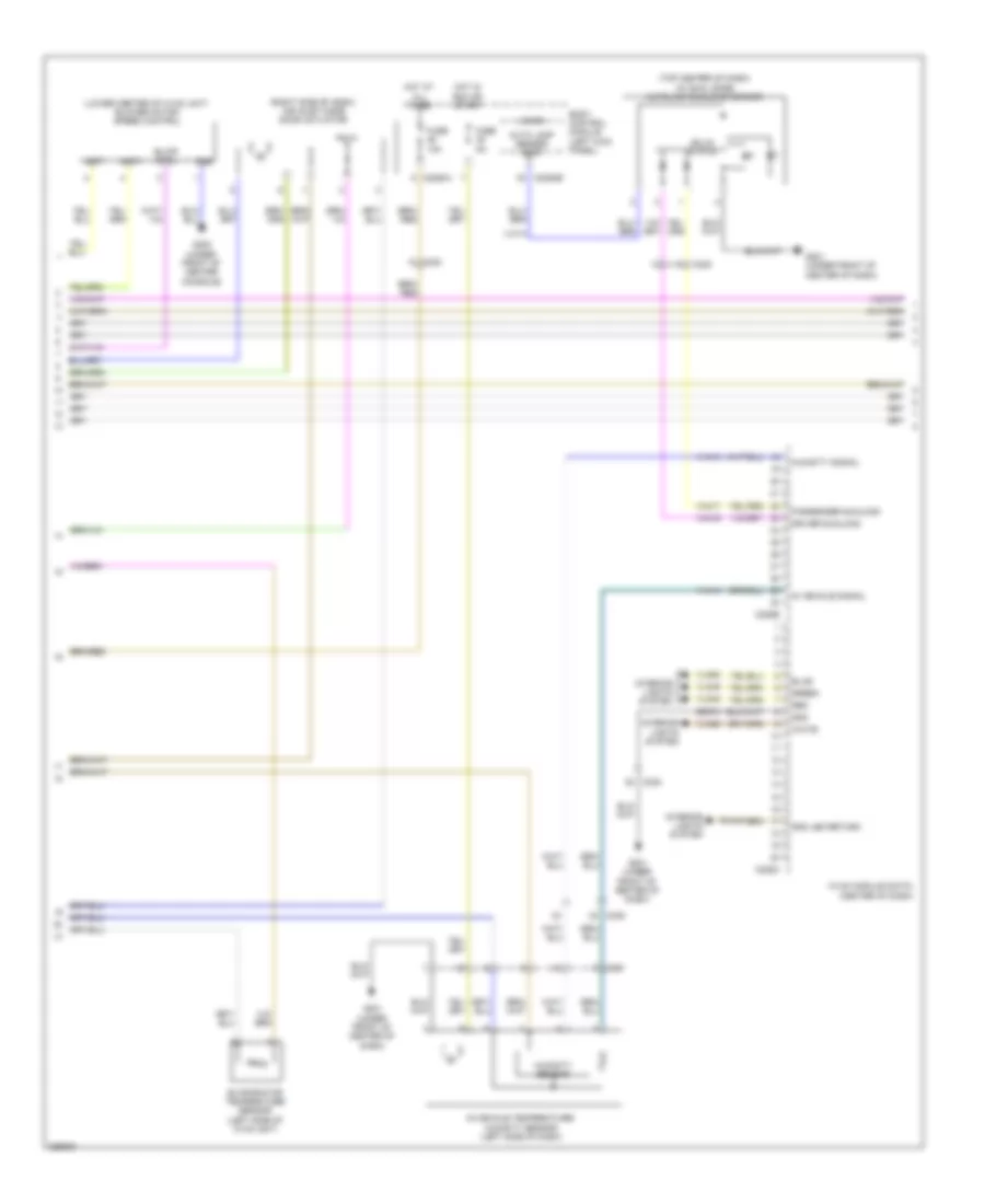
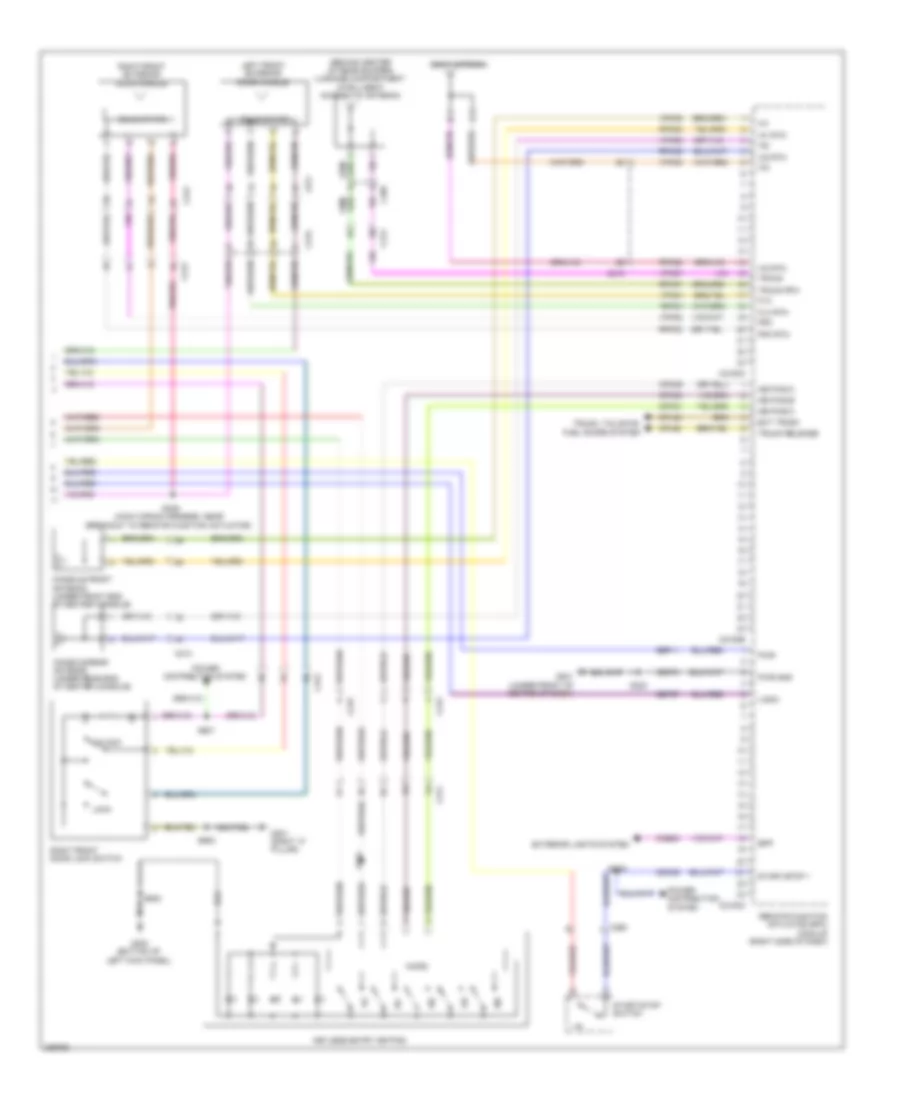
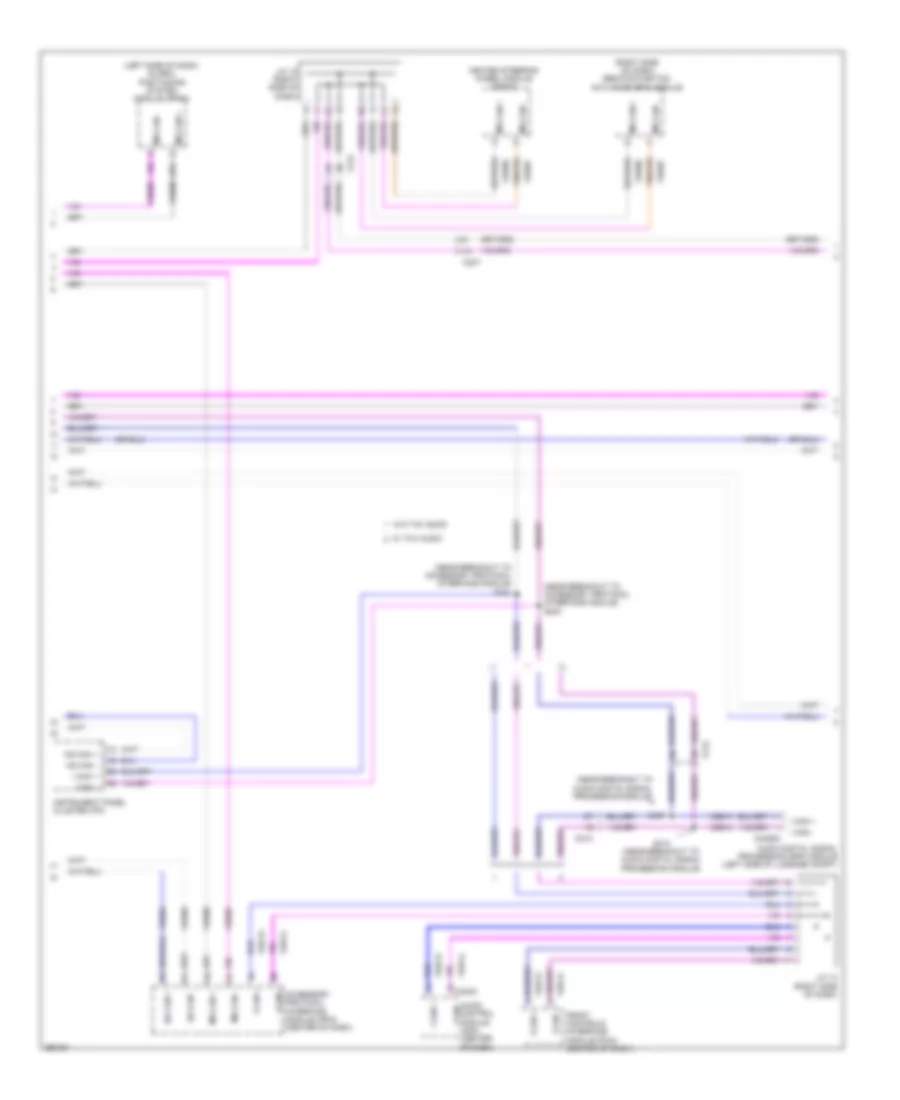
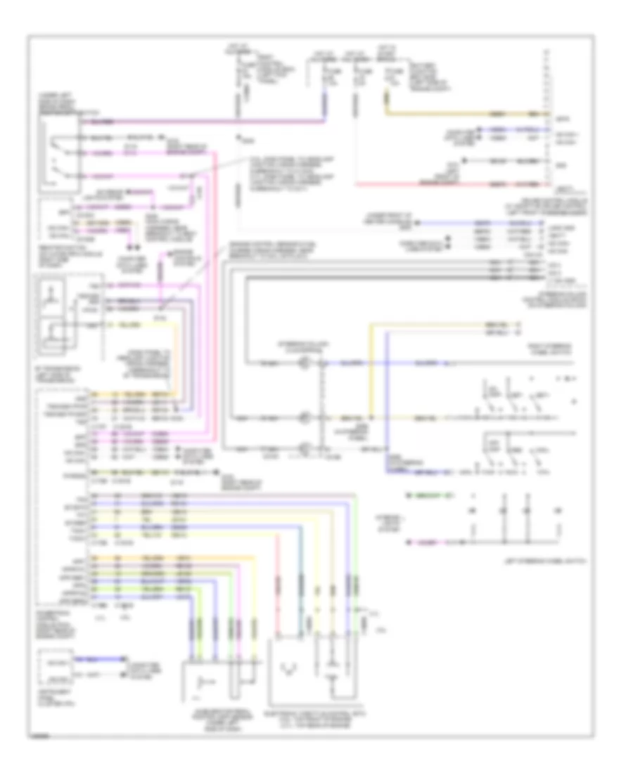
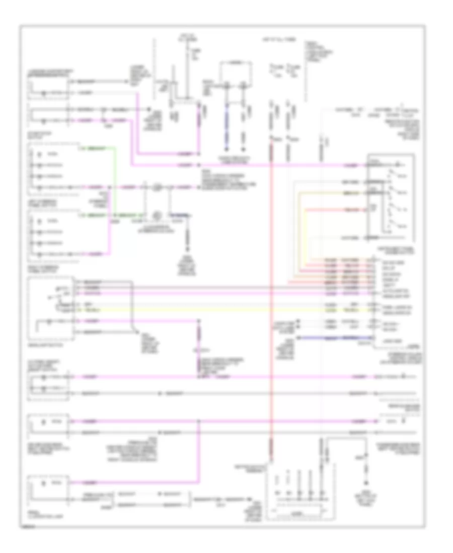
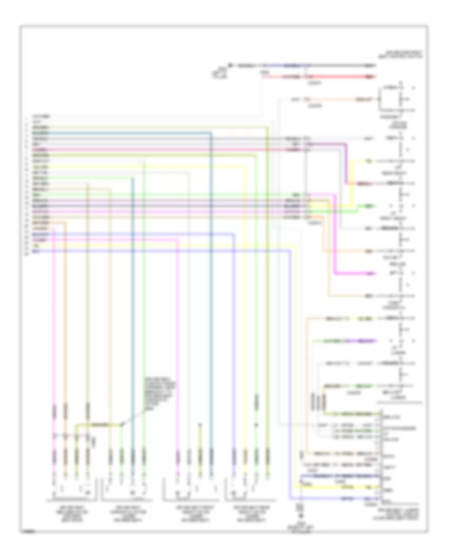
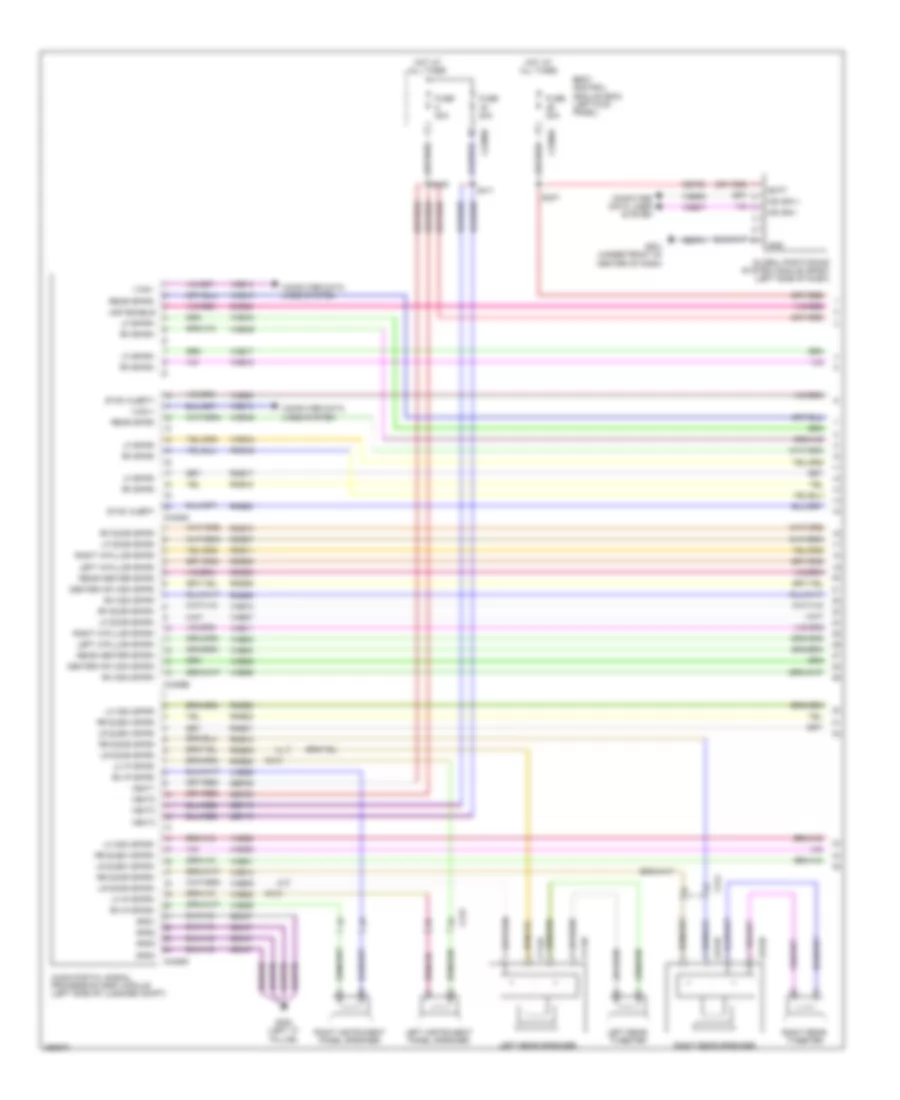
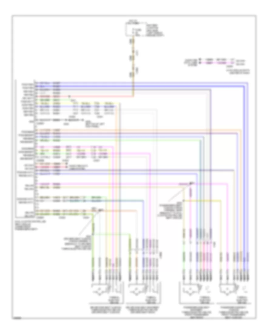
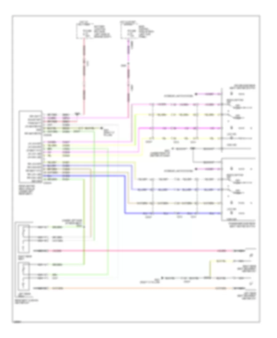
Automatic A/C Wiring Diagram (1 of 4) for Lincoln MKS EcoBoost 2013
 https://portal-diagnostov.com/license.html
Automotive Electricians Portal FZCO
Automotive Electricians Portal FZCO
https://portal-diagnostov.com/license.html
https://portal-diagnostov.com/license.html
Automotive Electricians Portal FZCO
Automotive Electricians Portal FZCO
List of elements for Automatic A/C Wiring Diagram (1 of 4) for Lincoln MKS EcoBoost 2013:
- (lower center of hvac unit) blower motor
- (main wiring harness, near breakout to blower motor) s202
- (main wiring harness, near breakout to glove box lamp) s209
- (main wiring harness, near breakout to glove box lamp) s234
- A/c clutch relay
- Battery junction box (bjb) (left side of engine compt)
- Blower motor relay
- Blwr rly
- C210
- C213
- C228a
- C228b
- C238
- C238 computer data lines system
- Ch122
- Ch123
- Ch207
- Ch208
- Ch212
- Ch213
- Ch228
- Ch229
- Ch238
- Ch239
- Defogger system
- Defrost req
- Defrost/panel/ floor mode door actuator (left side of hvac unit)
- Evap
- Feedback
- Fuse 10a
- Fuse 15a
- Fuse 40a
- Fuse 5a
- Fuse 7.5a
- G201 (under front of center of dash)
- Gd374
- Gnd
- Hot at all times
- Hot in start or run
- Hvac module (datc) (center of dash)
- Left side temperature blend door actuator (left side of hvac unit)
- Lh111
- Motor +
- Motor -
- Ms can +
- Ms can -
- Pcm power relay
- Return
- Rh111
- Right side temperature blend door actuator (top of hvac unit)
- S122
- S135
- S139
- Sbp46
- Var blwr ctrl
- Vbatt
- Vdb06
- Vdb07
- Vh101
- Vh406
- Vh436
- Vh438
- Vh440
- Vh441
- Vref
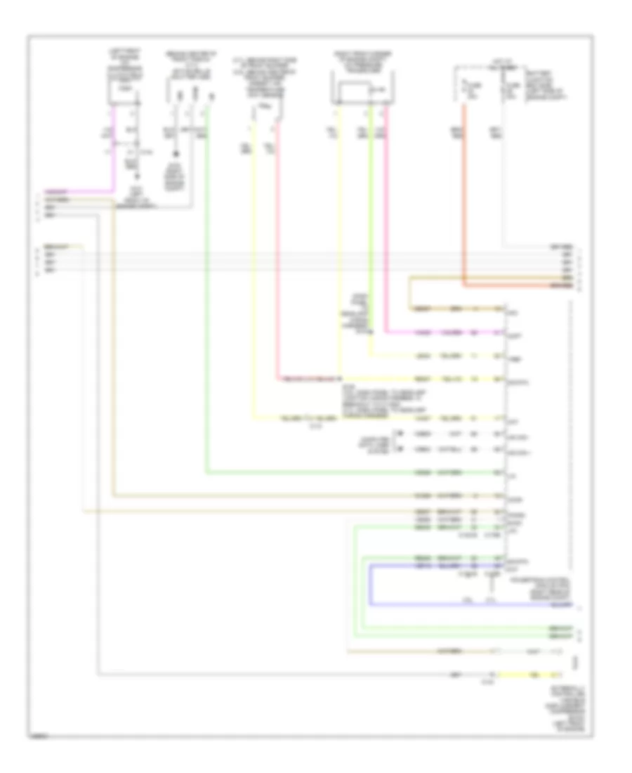
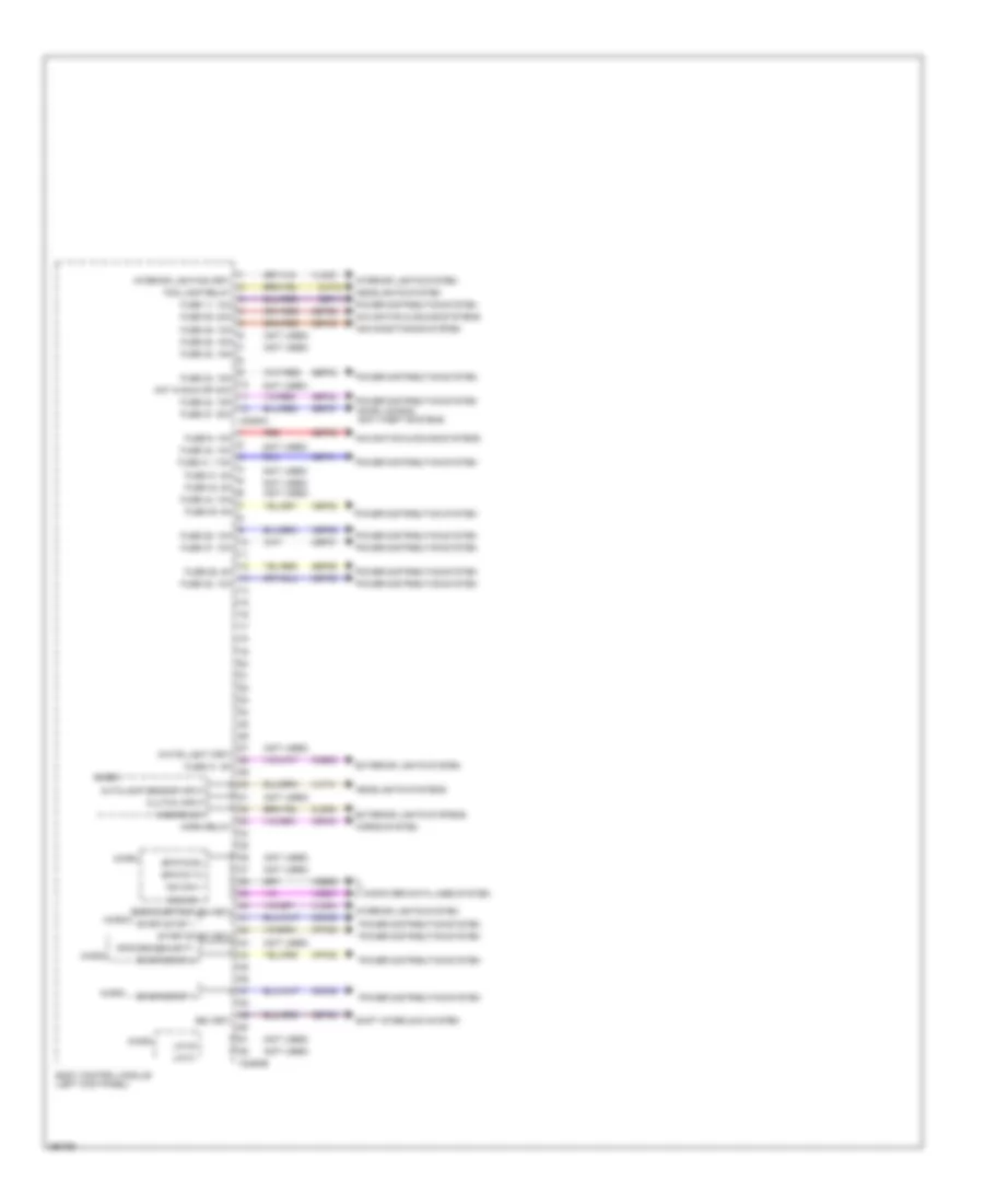
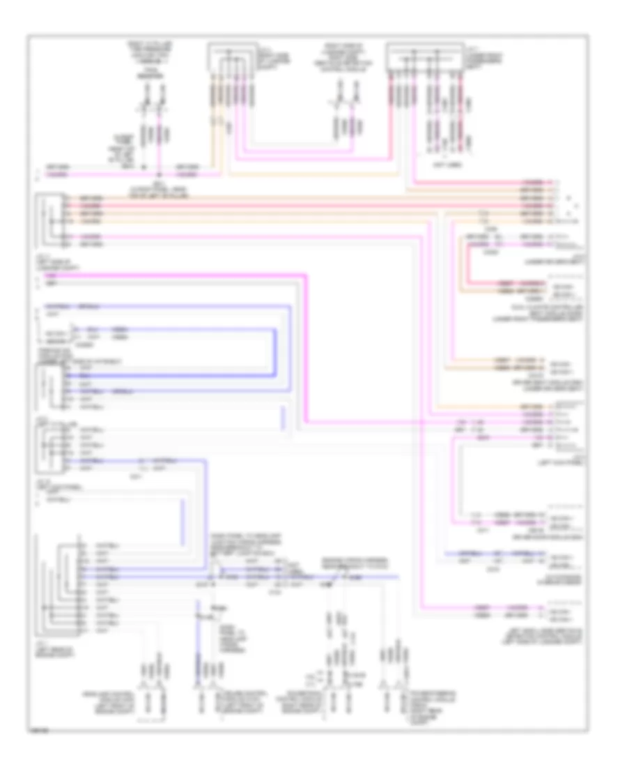
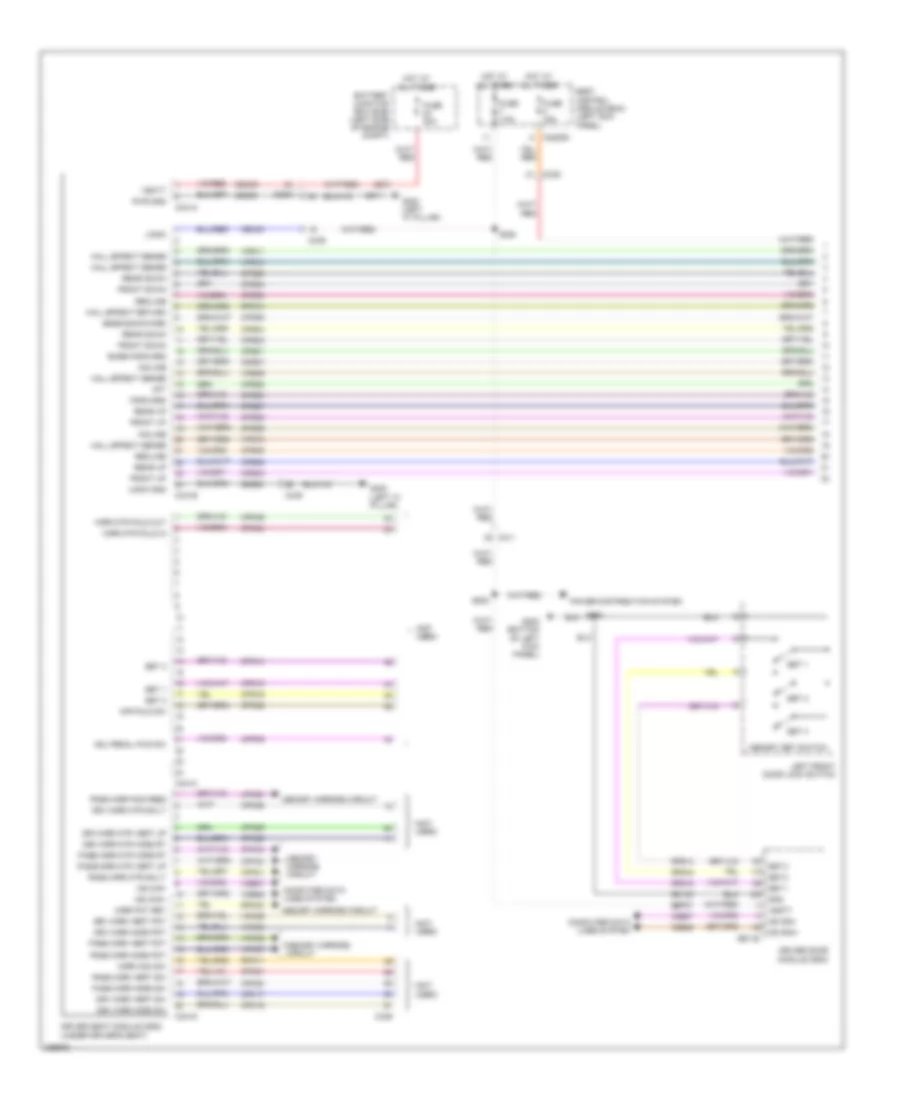
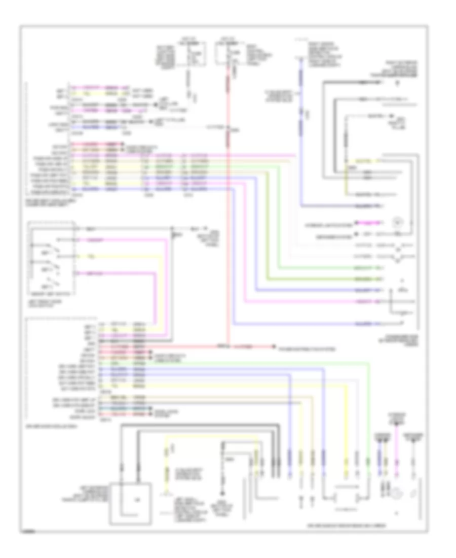
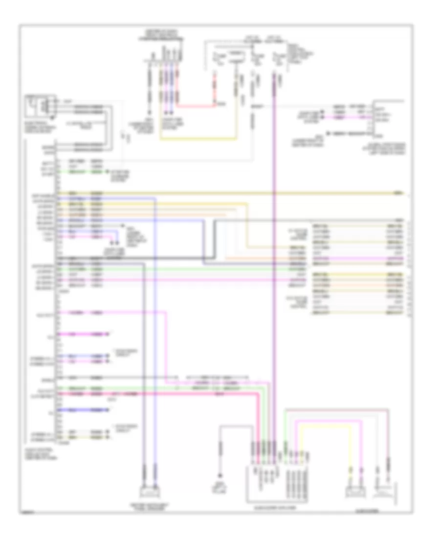
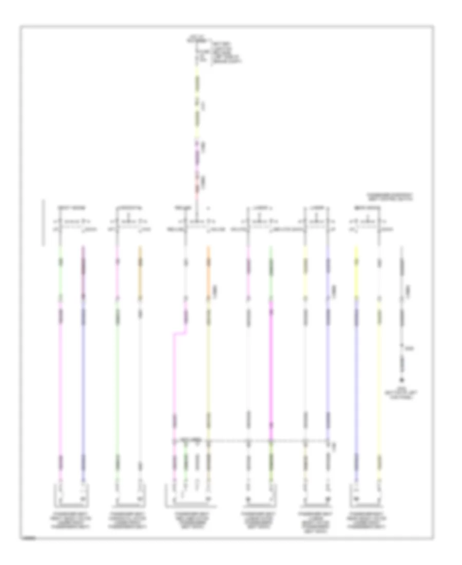
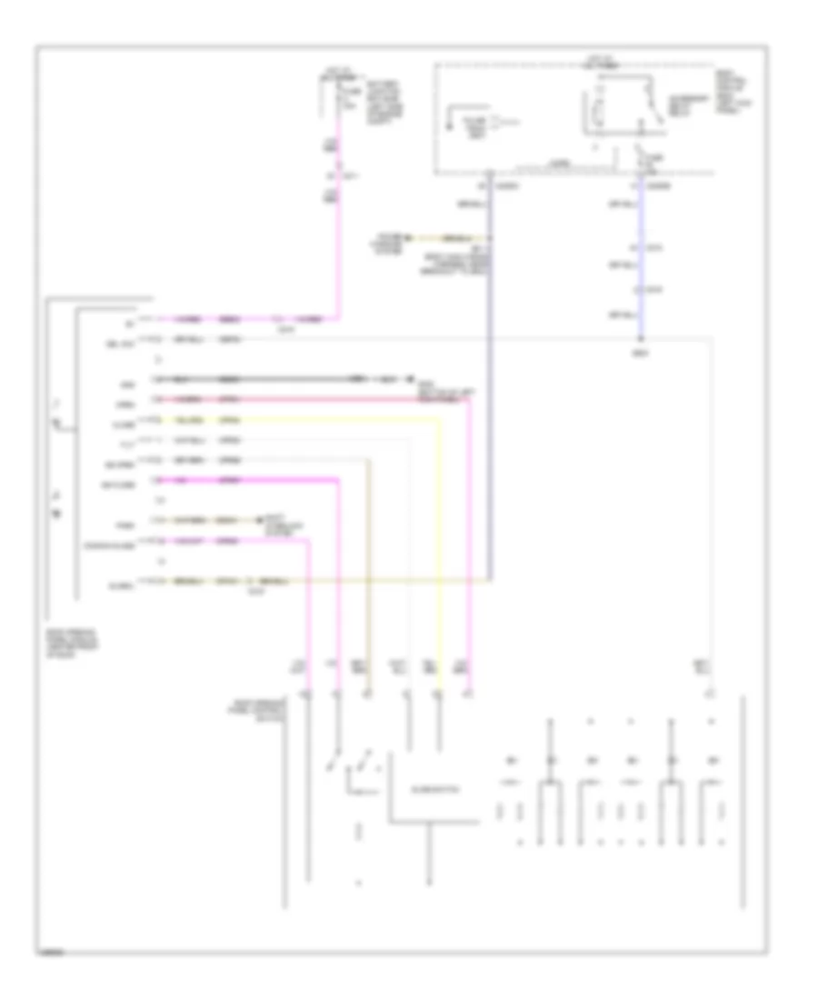
Automatic A/C Wiring Diagram (2 of 4) for Lincoln MKS EcoBoost 2013
List of elements for Automatic A/C Wiring Diagram (2 of 4) for Lincoln MKS EcoBoost 2013:
- (lower center of hvac unit) blower motor speed control
- (right side of dash) air inlet mode door actuator
- (top center of dash) (w/ dual zone) autolamp/sunload sensor
- Auto lamp sensor input
- Blwr ctrl
- Body control module (left kick panel)
- C2280a
- C2280b
- C228b
- C228c
- C238
- C260
- Driver sunload
- Evaporator temperature sensor (left side of hvac unit)
- Fuse 10a
- Fuse 5a
- G200 (under front of center console)
- G201 (under front of center of dash)
- Gd374
- Gnd
- Gnd led return
- Green
- Hot at all times
- Hot in run or start
- Humidity sensor
- Humidity signal
- Hvac module (datc) (center of dash)
- In vehicle signal
- In-vehicle temperature/ humidity sensor (left side of dash)
- Interior lights system
- Micro
- Mot+
- Mot-
- Passenger sunload
- Red
- Rln44
- Solid state
- Vh413
- Vh414
- Vh416
- Vh417
- Vlf14
- Vln48
- Vln49
- Vln50
- Vln58
- White
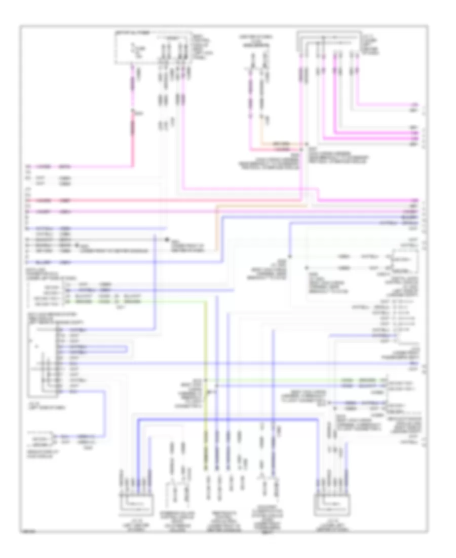
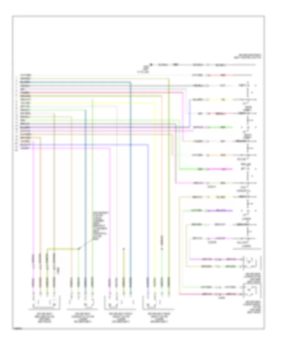
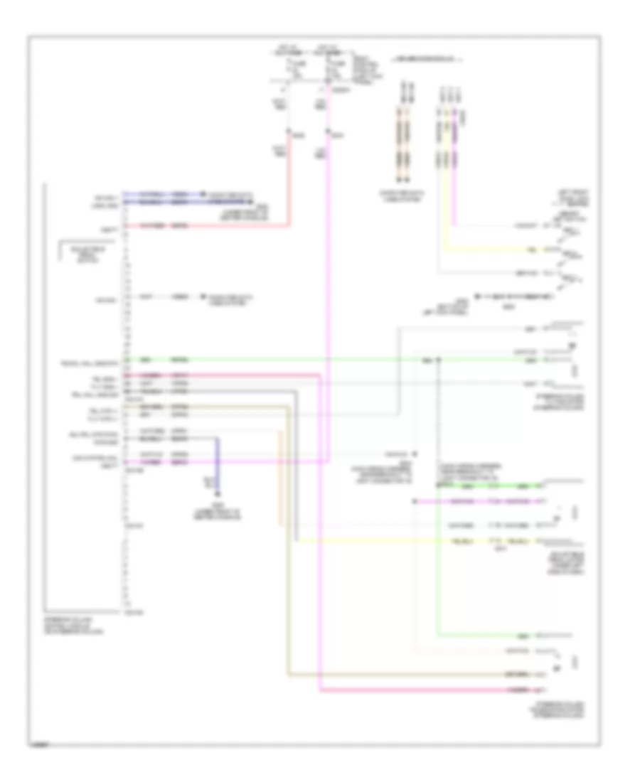
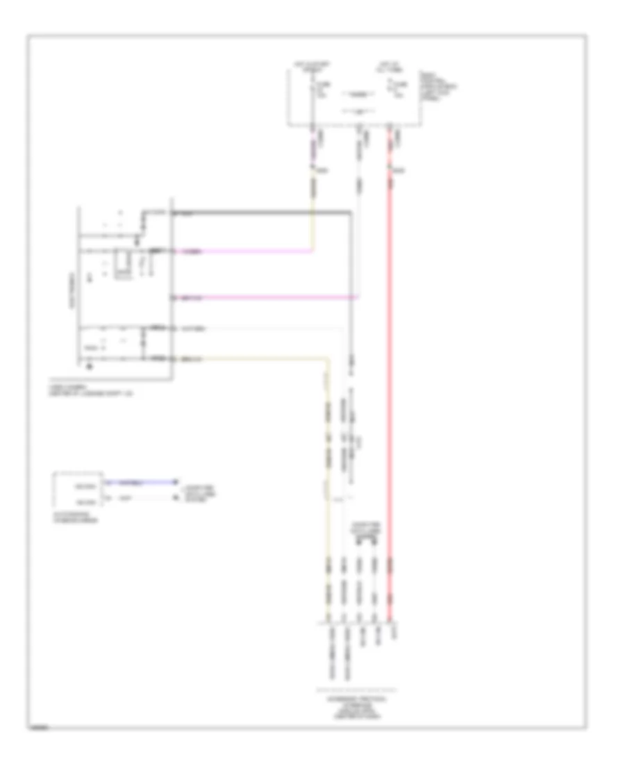
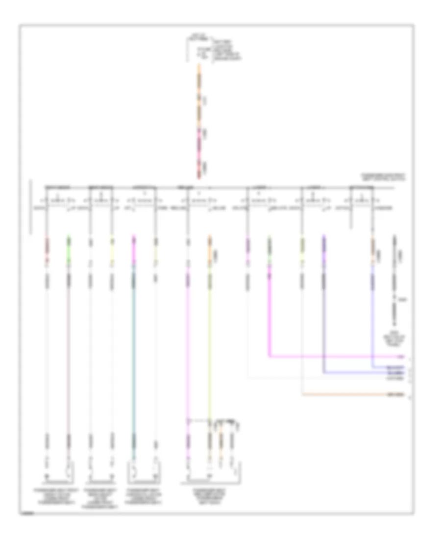
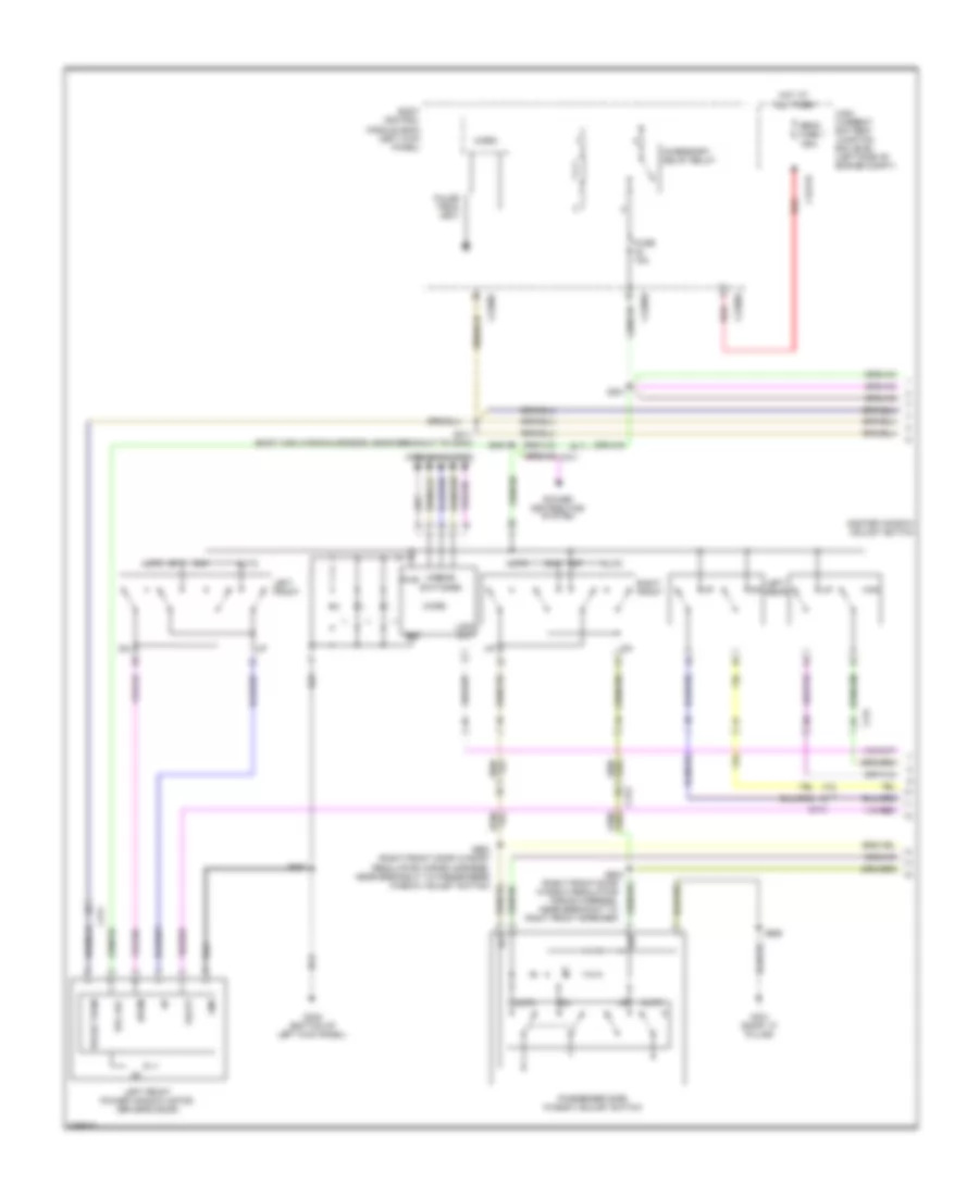
Automatic A/C Wiring Diagram (3 of 4) for Lincoln MKS EcoBoost 2013
List of elements for Automatic A/C Wiring Diagram (3 of 4) for Lincoln MKS EcoBoost 2013:
- (3.7l: behind right side of front bumper) (3.5l: behind center of front bumper) ambient air temperature (aat) sensor
- (behind center of front fascia) (3.7l) active grille shutter (ags)
- (dash panel to headlamp wiring harness) s144
- (left front of engine) a/c compressor clutch field coil
- (right front corner of engine compt) a/c pressure transducer
- 3.5l
- 3.7l
- Aat
- Accr
- Acpt
- Battery junction box (bjb) (left side of engine compt)
- C110
- C1381b
- C1381e
- C144
- C175b
- C175e
- Ce237
- Cec07
- Cec08
- Ch302
- Cht
- Computer data lines system
- Evdc
- Externally controlled variable displacement compressor (evdc) (left front of engine)
- Fuse 40a
- G100 (right side of engine compt)
- G101 (left front of engine compt)
- Gnd
- Hfc
- Hot at all times
- Hs can +
- Hs can -
- Le424
- Lfc
- Lin
- Pcmrc
- Powertrain control module (pcm) (right rear of engine compt)
- Re405
- Re407
- S125 (3.5l: dash panel to headlamp junction wiring harness, in breakout to c1100d) (3.7l: dash panel to headlamp wiring harness)
- Sig rtn
- Vdb04
- Vdb05
- Vdn06
- Ve462
- Ve712
- Vh407
- Vh433
- Vpwr
- Vref
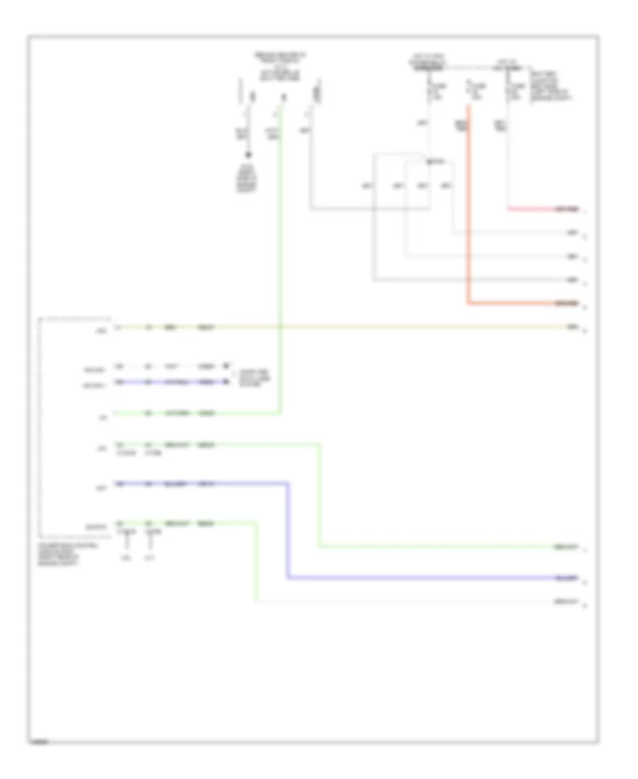
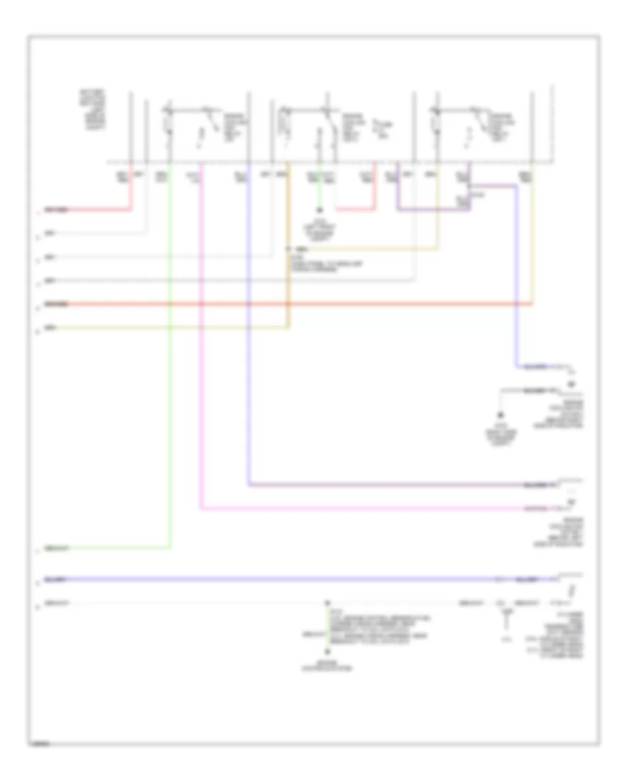
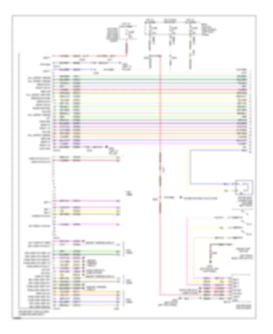
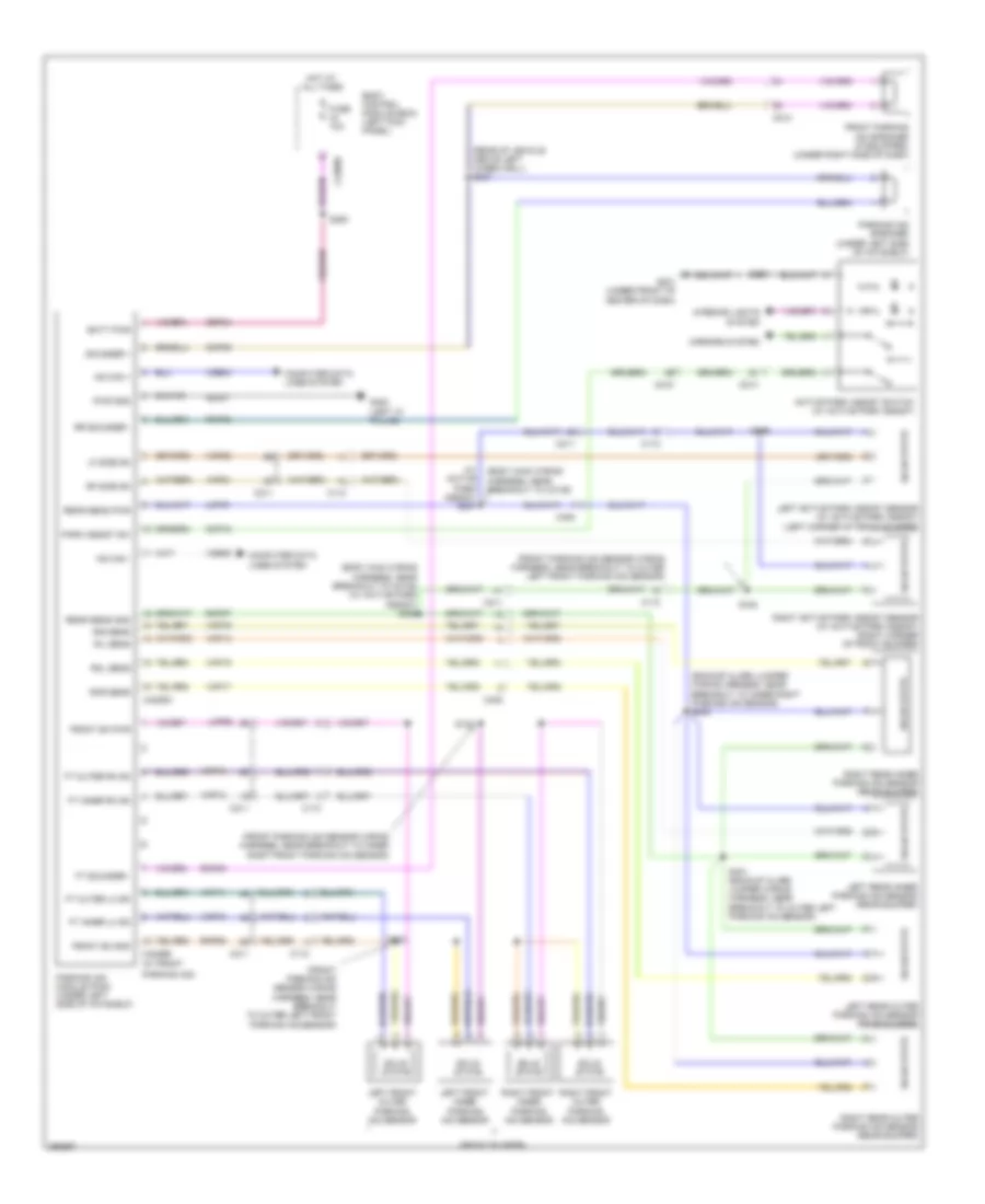
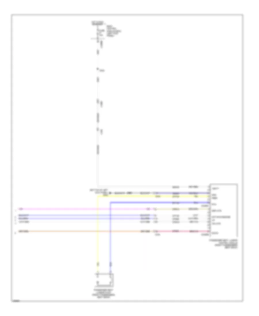
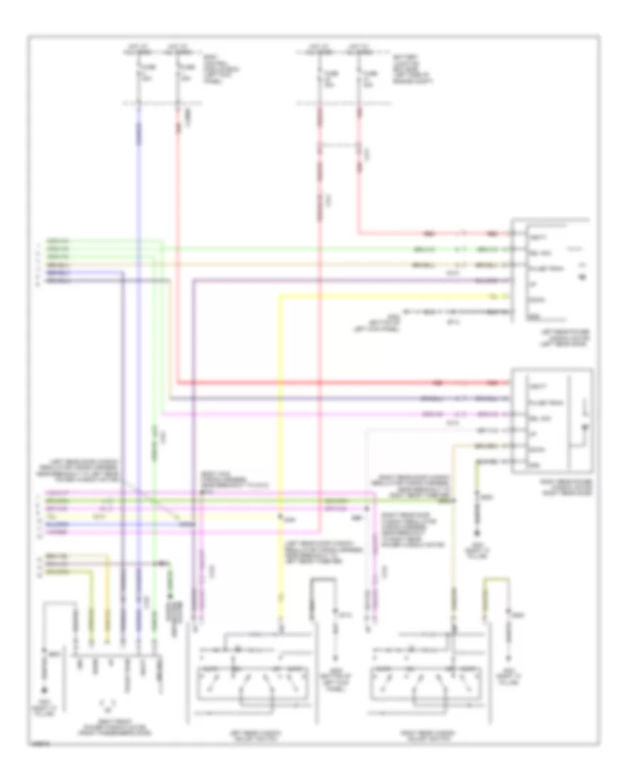
Automatic A/C Wiring Diagram (4 of 4) for Lincoln MKS EcoBoost 2013
List of elements for Automatic A/C Wiring Diagram (4 of 4) for Lincoln MKS EcoBoost 2013:
- 3.7l
- Battery junction box (bjb) (left side of engine compt)
- C192
- Cylinder head temperature (cht) sensor (3.5l: middle of right cylinder head) (3.7l: front of right cylinder head)
- Engine controls system
- Engine cooling fan motor 1 (behind left side of radiator)
- Engine cooling fan motor 2 (behind right side of radiator)
- Engine cooling fan relay hfc 1
- Engine cooling fan relay hfc 2
- Engine cooling fan relay lfc
- Fuse 25a
- G100 (right side of engine compt)
- G101 (left front of engine compt)
- S155 (dash panel to headlamp wiring harness)
ANTI-LOCK BRAKES
Anti-lock Brakes Wiring Diagram for Lincoln MKS EcoBoost 2013
List of elements for Anti-lock Brakes Wiring Diagram for Lincoln MKS EcoBoost 2013:
- (in breakout to joint connector 4) s415
- (left front of engine compt) g101
- (not used)
- (under left side of dash) brake pedal position (bpp) switch
- 3.5l
- 3.7l
- Anti-lock brake system (abs) module (left rear of engine compt)
- Battery junction box (bjb) (left side of engine compt)
- Body control module (left kick panel)
- Bpp
- Bps
- Brake booster vacuum sensor (on vacuum brake booster assembly)
- C1381b
- C144
- C175b
- C210
- C211
- C2280a
- C2280b
- C2280f
- C2414a
- C3007
- C310b
- C4396c
- Cbb92
- Ccb08
- Ces09
- Computer data lines system
- Fuse 10a
- Fuse 15a
- Fuse 20a
- Fuse 50a
- Fuse 5a
- G101 (left front of engine compt)
- G102 (right rear of engine compt)
- G200 (under front of center console)
- Gd120
- Gd375
- Gnd
- Hot at all times
- Hot in start or run
- Hs can +
- Hs can -
- Hs can yaw+
- Hs can yaw-
- Instrument panel cluster
- Lca36
- Left front wheel speed sensor (left front wheel hub assembly)
- Left rear wheel speed sensor (left rear wheel hub assembly)
- Lf sensor hi
- Lf sensor lo
- Logic gnd
- Lr sensor hi
- Lr sensor lo
- Micro
- Mtr b+
- Nca
- Powertrain control module (right rear of engine compt)
- Rca17
- Rca18
- Rca19
- Rca20
- Rca36
- Restraints control module (under front of center console)
- Rf sensor hi
- Rf sensor lo
- Right front wheel speed sensor (right front wheel hub assembly)
- Right rear wheel speed sensor (right rear wheel hub assembly)
- Rr sensor hi
- Rr sensor lo
- Run
- S111
- S116 (3.5l)
- S180
- S245
- S246
- S414 (in breakout to joint connector 4)
- Sbb05
- Sbb43
- Sbp23
- Steering column control module (on steering column)
- Steering wheel angle sensor
- Vacum return
- Vacum sig
- Vacuum pwr
- Valve b+
- Vbatt
- Vca03
- Vca04
- Vca05
- Vca06
- Vca23
- Vca24
- Vca37
- Vdb04
- Vdb05
- Vehicle dynamics module (right side of luggage compt)
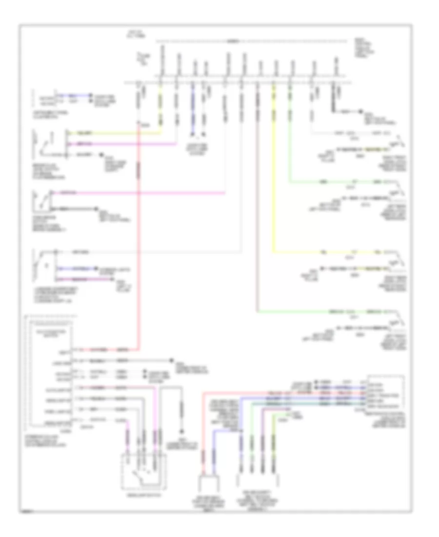
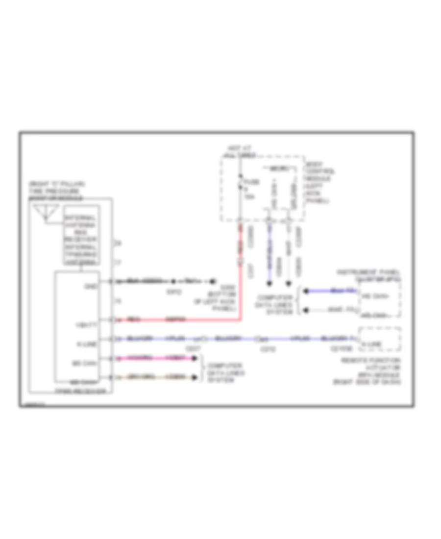
ANTI-THEFT
Anti-theft Wiring Diagram (1 of 2) for Lincoln MKS EcoBoost 2013
List of elements for Anti-theft Wiring Diagram (1 of 2) for Lincoln MKS EcoBoost 2013:
- (bottom of left kick panel) g302
- (right "c" pillar)
- (right "c" pillar) g301
- (under front of center of dash) g201
- Acce- ssory delay relay
- Ajar
- Backup transceiver (right end of dash)
- Body control module (left kick panel)
- C212
- C215
- C2153d
- C2153e
- C2280a
- C2280b
- C2280c
- C2280d
- C2280e
- C2280f
- C237
- C311
- C312
- C313
- C314
- C501a
- C501b
- Clf02
- Clock
- Computer data lines system
- Cpk19
- Cpk23
- Cpk28
- Cpl11
- Cpl25
- Cpl26
- Cpl31
- Cpl36
- Cpl39
- Cpl51
- Cpl52
- Cpl84
- Crh04
- Data
- Dr lock
- Dr unlock
- Driver door module (ddm)
- Drv unlock
- Fl ajar
- Fr ajar
- Fuse 10a
- Fuse 15a
- Fuse 20a
- Fuse 5a
- Fuse 7.5a
- G100 (right side of engine compt)
- G201 (under front of center of dash)
- G301
- G302 (bottom of left kick panel)
- Gd374
- Gnd
- Headlights system
- Hood ajar
- Hood switch (left front of engine compt)
- Horn relay
- Horns system
- Hot at all times
- Internal antenna rke receiver
- Internal tpms/rke antenna
- K-line
- Keypad illum
- Left front door latch (rear of left front door)
- Left front door lock switch
- Left hi beam (fet)
- Left rear door latch (rear of left rear door)
- Lock
- Logic gnd
- Lpk32
- Lr ajar
- Memory set switch
- Memory systems
- Micro
- Ms can +
- Ms can -
- Ms can+
- Ms can-
- Pass lock
- Pass unlock
- Pats gnd
- Pats vcc
- Power distribution system
- Pwr gnd
- Remote function actuator (rfa) module (right side of dash)
- Right front door latch (rear of right front door)
- Right rear door latch (rear of right rear door)
- Rpk32
- Rpk39
- Rr ajar
- S201
- S223
- S237
- S306 (body main wiring harness, near breakout to c313)
- S321 (body main wiring harness, near breakout to c3375)
- S364
- S500
- S504
- S600
- S800
- Set 1
- Set 2
- Set 3
- State solid
- Tire pressure monitor module (right "c" pillar)
- Tpms receiver
- Trunk release
- Trunk, tailgate, fuel doors system
- Unlock
- Vcc
- Vdb06
- Vdb07
- Vpk32
- Vpk33
- Vpk39
- Vpk40
- Vpl56
Anti-theft Wiring Diagram (2 of 2) for Lincoln MKS EcoBoost 2013
List of elements for Anti-theft Wiring Diagram (2 of 2) for Lincoln MKS EcoBoost 2013:
- (behind center of rear bumper) luggage compartment intelligent access (ia) antenna
- 1/2
- 3/4
- 5/6
- 7/8
- 9/0
- Bpp
- C212
- C214
- C215
- C2153a
- C2153b
- C2153c
- C260
- C311
- C312
- C405
- Ccb08
- Cdc35
- Console front antenna (under front end of center console)
- Console rear antenna (under rear end of center console)
- Cpk29
- Cpk30
- Cpk31
- Cpl45
- Cpl60
- Ext trunk
- Exterior lights system
- Fla
- Fla rtn
- Fra
- Fra rtn
- G201 (under front of center of dash)
- G301 (right "c" pillar)
- G302 (bottom of left kick panel)
- Gd374
- Ia1
- Ia1 rtn
- Ia2
- Ia2 rtn
- Ia3
- Ia3 rtn
- Keyless entry keypad
- Keypad a
- Keypad b
- Keypad c
- Left front exterior door handle
- Lock
- Logic
- Micro
- Power distribution system
- Pwr
- Pwr gnd
- Remote function actuator (rfa) module (right side of dash)
- Right front door lock switch
- Right front exterior door handle
- Rpk01
- Rpk02
- Rpk05
- Rpk06
- Rpk07
- Rpk08
- S223
- S229 (main wiring harness, near breakout to remote function actuator)
- S242
- S500
- S502
- S600
- S601
- Sbp11
- Sbp27
- Seat antenna
- Solid state
- Start/stop 1
- Start/stop switch
- Trunk
- Trunk release
- Trunk rtn
- Trunk, tailgate, fuel doors system
- Unlock
- Vpk01
- Vpk02
- Vpk05
- Vpk06
- Vpk07
- Vpk08
BODY CONTROL MODULES
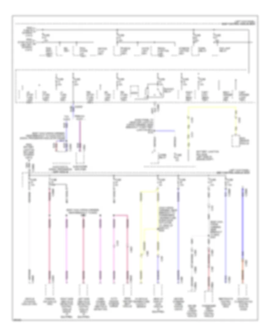
Body Control Modules Wiring Diagram (1 of 2) for Lincoln MKS EcoBoost 2013
List of elements for Body Control Modules Wiring Diagram (1 of 2) for Lincoln MKS EcoBoost 2013:
- (not used)
- Air conditioning system
- Autolamp sensor input
- Backlighting led (fet)
- Body control module (left kick panel)
- Bsi (fet)
- C2280a
- C2280b
- Cbp35
- Cbp36
- Cbp37
- Cbp38
- Cbp41
- Ccb08
- Cdc35
- Cet53
- Clf12
- Cls32
- Clutch input
- Computer data lines system
- Cpk35
- Cpk36
- Crh04
- Epats rx
- Epats tx
- Exterior lights system
- Exterior lights systems
- Fog lamp relay
- Fuse 11, 10a
- Fuse 23, 15a
- Fuse 24, 15a
- Fuse 26, 5a
- Fuse 27, 20a
- Fuse 28, 15a
- Fuse 29, 20a
- Fuse 31, 5a
- Fuse 32, 15a
- Fuse 34, 10a
- Fuse 35, 5a
- Fuse 36, 10a
- Fuse 37, 10a
- Fuse 38, 10a
- Fuse 41, 7.5a
- Fuse 42, 5a
- Fuse 44, 10a
- Fuse 46, 10a
- Fuse 9, 10a
- Hazard sw
- Headlights system
- Headlights systems
- Horn relay
- Horns system
- Hot in run or acc
- Interior lighting (fet)
- Interior lights system
- Lin 01
- Lin 04
- Micro
- Ms can +
- Ms can -
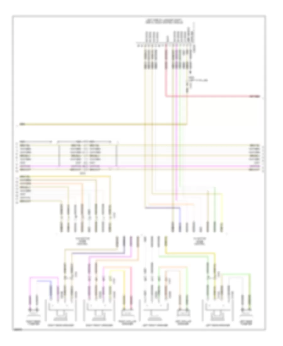
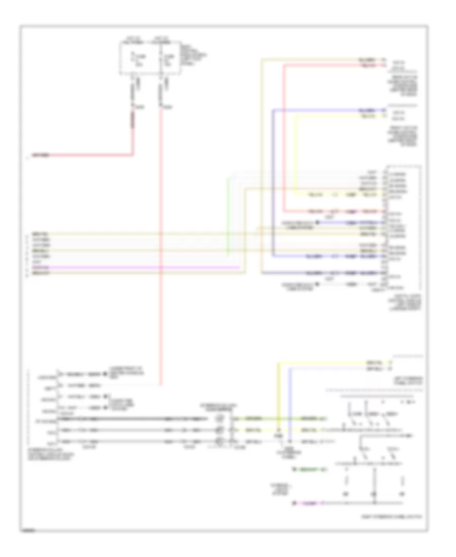
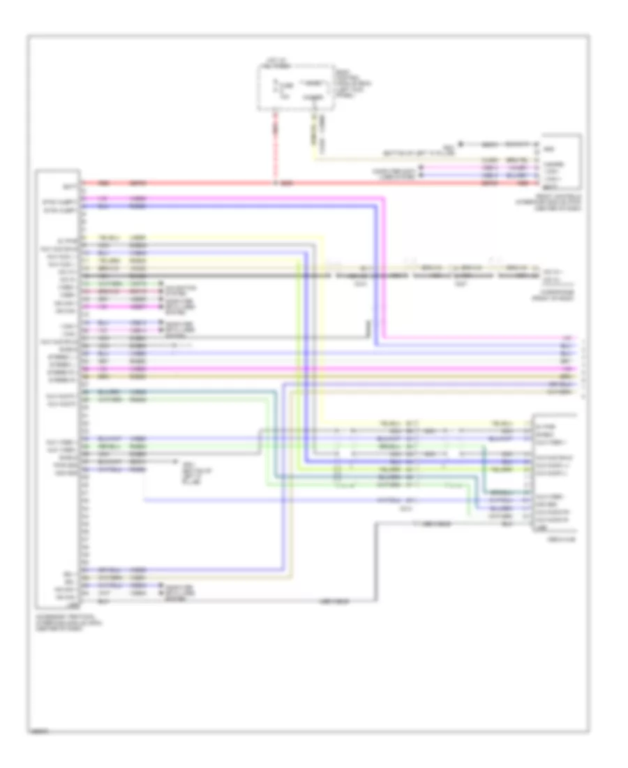
- Navigation & sound systems
- Power distribution system
- Power distribution system door locks & anti-theft systems
- Red
- Ripcord security
- Sbp09
- Sbp11
- Sbp23
- Sbp24
- Sbp26
- Sbp27
- Sbp29
- Sbp46
- Shift interlock system
- Start/stop (fet)
- Start/stop 1
- Start/stop 2
- Vdb06
- Vdb07
- Vlf14
- Vln04
- Vln33
- White light (fet)
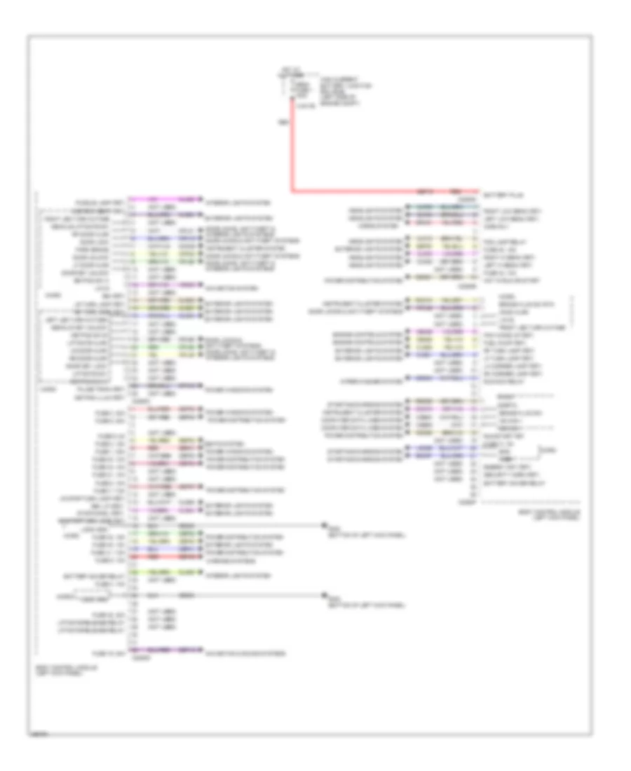
Body Control Modules Wiring Diagram (2 of 2) for Lincoln MKS EcoBoost 2013
List of elements for Body Control Modules Wiring Diagram (2 of 2) for Lincoln MKS EcoBoost 2013:
- (not used)
- 2nd row seat (fet)
- Battery plus
- Battery saver relay
- Bcs
- Body control module (left kick panel)
- Brake fluid sw
- Brake fluid sw rtn
- Bsi (fet)
- C2280c
- C2280d
- C2280e
- C2280f
- C2280g
- Cbp30
- Cbp32
- Cbp33
- Cbp34
- Cbp40
- Cbp41
- Cdc21
- Cdc55
- Cdc64
- Ce226
- Ce436
- Clf02
- Clf03
- Clf04
- Clf05
- Clf12
- Cln09
- Cln25
- Cls21
- Cls23
- Cls25
- Cls27
- Cls28
- Cls44
- Cls54
- Cls55
- Cmc19
- Cmc25
- Computer data lines system
- Cpk19
- Cpk23
- Cpl25
- Cpl26
- Cpl31
- Cpl36
- Cpl39
- Cpl58
- Cpw01
- Decklid key unlock
- Decklid/liftgate sw
- Door key lock
- Door key unlock
- Door lock
- Door locks & anti-theft systems
- Door locks & anti-theft systems door locks, anti-theft & interior lights systems
- Door locks, anti-theft & interior lights systems
- Door unlock
- Energy mgt (fet)
- Engine controls system
- Exterior lights system
- Fog lamp relay
- Front led turn outage
- Fuel pump (fet)
- Fuse 1, 30a
- Fuse 19, 20a
- Fuse 2, 15a
- Fuse 21, 10a
- Fuse 3, 30a
- Fuse 30, 15a
- Fuse 31, 5a
- Fuse 32, 15a
- Fuse 33, 10a
- Fuse 34, 10a
- Fuse 4, 10a
- Fuse 40, 10a
- Fuse 41, 7.5a
- Fuse 43, 10a
- Fuse 48, 30a
- Fuse 5, 20a
- Fuse 6, 5a
- Fuse 7, 7.5a
- Fuse 8, 10a
- Fuse 9, 10a
- G302 (bottom of left kick panel)
- Gd233
- Headlights system
- High current battery junction box (bjb) (left side of engine compt) c1617b
- Hood ajar
- Horn rly
- Horns system
- Hot at all times
- Hot in run or start
- Hs can +
- Hs can -
- Instrument cluster system
- Interior lights system
- Keypad illum (fet)
- Keypad sw a
- Keypad sw b
- Keypad sw c
- Ldc59
- Left hi beam (fet)
- Left led turn outage
- Left low beam (fet)
- Lf door ajar
- Lf turn lamp (fet)
- Lh corner lamp (fet)
- Liftgate ajar
- Liftgate release relay
- Liftgate sw
- Lin 02
- Lin 03
- Logic gnd
- Lr door ajar
- Lr stop/turn lamp (fet)
- Lr turn lamp (fet)
- Mega fuse 1 100a
- Micro
- Navigation & sound systems
- Navigation system
- Park brake
- Pcm wake up (fet)
- Power distribution system
- Power windows system
- Puddle lamp (fet)
- Pulse train (fet)
- Rdc59
- Red
- Rev lp (fet)
- Rf door ajar
- Rf turn lamp (fet)
- Rh corner lamp (fet)
- Right hi beam (fet)
- Right led turn outage
- Right low beam (fet)
- Rmc19
- Rr door ajar
- Rr stop/turn lamp (fet)
- Rr turn lamp (fet)
- Run/acc relay
- Run/start fet
- Sbf16
- Sbp01
- Sbp02
- Sbp03
- Sbp05
- Sbp07
- Sbp09
- Sbp19
- Sdc57
- Seats system
- Security horn (fet)
- Sigrtn
- Srh01
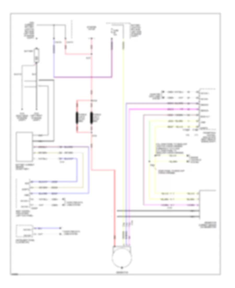
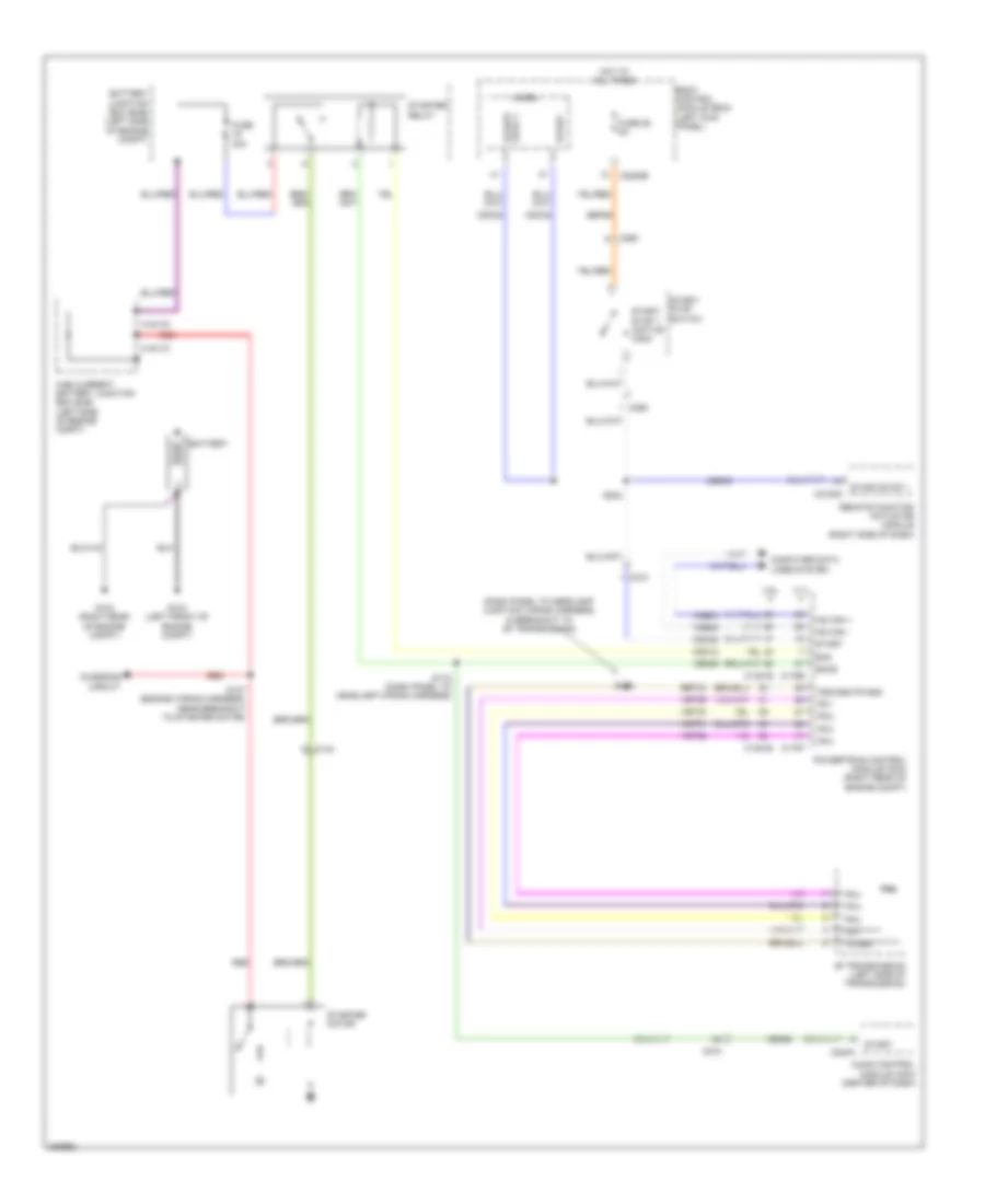
- Starting/charging system
- Stop/chmsl (fet)
- Vdb04
- Vdb05
- Vdn03
- Vref
- Warning systems
- Wiper/washer system
COMPUTER DATA LINES
Computer Data Lines Wiring Diagram (1 of 3) for Lincoln MKS EcoBoost 2013
List of elements for Computer Data Lines Wiring Diagram (1 of 3) for Lincoln MKS EcoBoost 2013:
- (body main wiring harness, in breakout to joint connector 4) s418
- (center of dash) hvac module-datc
- Anti-lock brake system (abs) module (left rear of engine compt)
- Body control module (bcm) (left kick panel)
- C210
- C211
- C212
- C2280a
- C2280b
- C2280f
- C228a
- C238
- C2414a
- C248
- C310b
- C3382
- C3521a
- C4396a
- C4396c
- Data link connector (dlc) (under left side of dash)
- Digital audio control module (w/ anc) (left side of luggage compt)
- Fuse 15a
- G200 (under front of center console)
- G201 (under front of center of dash)
- Gd374
- Gd375
- Headup display (hud) module
- Hot at all times
- Hs can +
- Hs can -
- Hs can yaw +
- Hs can yaw -
- J/c 15 (lower left center of dash)
- J/c 16 (left center of dash)
- J/c 17 (lower left center of dash)
- J/c 18 (left side of dash)
- J/c 6 (under front passenger's seat)
- Micro
- Ms can +
- Ms can -
- Occupant classification system module (ocsm) (under front passenger's seat)
- Restraints control module (rcm) (under front of center console)
- S222 (main wiring harness, near breakout to accessory protocol interface module)
- S227 (main wiring harness near breakout to accessory protocol interface module)
- S243
- S325 (w/ anc) (body main wiring harness, near breakout to c3135)
- S326 (w/ anc) (body main wiring harness, near breakout to c3135)
- S414
- S415 (body main wiring harness, in breakout to joint connector 4)
- S419 (body main wiring harness, in breakout to joint connector 4)
- Sbp24
- Steering column control module (sccm) (on steering column)
- Vca23
- Vca24
- Vdb04
- Vdb05
- Vdb06
- Vdb07
- Vdb13
- Vdb14
- Vehicle dynamics module (vdm) (right side of luggage compt)
Computer Data Lines Wiring Diagram (2 of 3) for Lincoln MKS EcoBoost 2013
List of elements for Computer Data Lines Wiring Diagram (2 of 3) for Lincoln MKS EcoBoost 2013:
- (left side of dash) global positioning system module (gpsm)
- (near breakout to accessory protocol interface module) s240
- (near breakout to accessory protocol interface module) s241
- (near breakout to audio digital signal processing module)
- (right side of dash) remote function actuator (rfa) module
- Accessory protocol interface module (apim) (center of dash)
- Audio digital signal processing (dsp) module (left side of luggage compt)
- C212
- C237
- C240a
- C4326a
- Front controls interface module (fcim) (center of dash)
- Heated steering wheel module (hswm)
- Hs can +
- Hs can -
- I can +
- I can -
- I can - audio control module (acm) (center of dash)
- Instrument panel cluster (ipc)
- J/c 12 (right side of dash)
- J/c 14 (right side of dash)
- Ms can +
- Ms can -
- S407
- S410 (near breakout to audio digital signal processing module)
- Vdb04
- Vdb05
- Vdb06
- Vdb07
- Vdb13
- Vdb14
- W/ thx audio
- W/o thx audio
Computer Data Lines Wiring Diagram (3 of 3) for Lincoln MKS EcoBoost 2013
List of elements for Computer Data Lines Wiring Diagram (3 of 3) for Lincoln MKS EcoBoost 2013:
- (dash panel to headlamp junction wiring harness, near breakout to battery junction box)
- (dash panel to headlamp wiring harness)
- (engine wiring harness, near breakout to g104)
- (in roof panel,
- (not used)
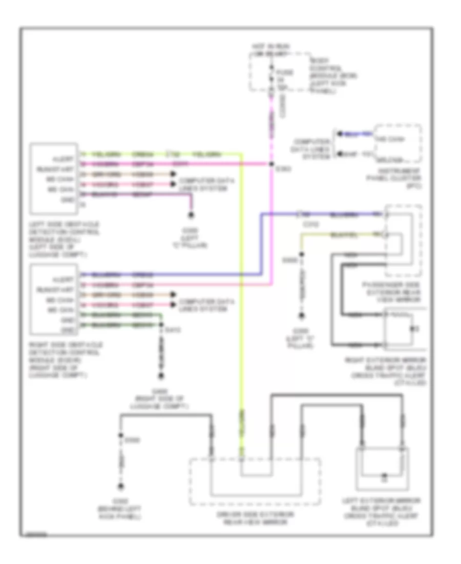
- (right "c" pillar) tire pressure monitor (tpm) module
- (right side of luggage compt) right side obstacle detection control module
- 3.5l
- 3.7l
- Auto-dimming interior mirror
- C1381b
- C144
- C1467a
- C175b
- C211
- C215
- C219
- C237
- C3050
- C311
- C3265c
- C3381
- C3382
- C339
- C340
- C341d
- C4226a
- C501b
- Cruise control module (c-cm) (left front of engine compt)
- Driver door module (ddm)
- Driver seat module (dsm) (under driver's seat)
- Dual climate controlled seat module (dcsm) (under front passenger's seat)
- Headlamp control module (hcm) (left front of engine compt)
- Hs can +
- Hs can -
- J/c 1 (left rear of engine compt)
- J/c 10 (left kick panel)
- J/c 11 (left side of luggage compt)
- J/c 2 (left "c" pillar)
- J/c 4 (right side of luggage compt)
- J/c 5 (under driver's seat)
- J/c 7 (under front passenger's seat)
- J/c 8 (left kick panel)
- Left (sod-l) side obstacle detection control module (left side of luggage compt)
- Ms can +
- Ms can -
- Near top of left "b" pillar) s910
- Parking aid module (pam) (under left side of hatshelf)
- Power steering control module (pscm) (right rear of engine compt)
- Powertrain control module (right rear of engine compt)
- S136
- S137
- S149
- S154
- S166
- S167
- S911 (in roof panel, near top of left "b" pillar)
- Tpms receiver
- Vdb04
- Vdb05
- Vdb06
- Vdb07
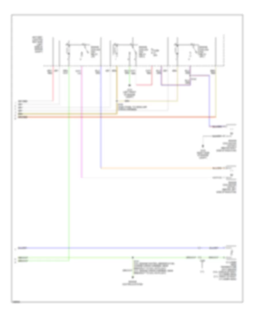
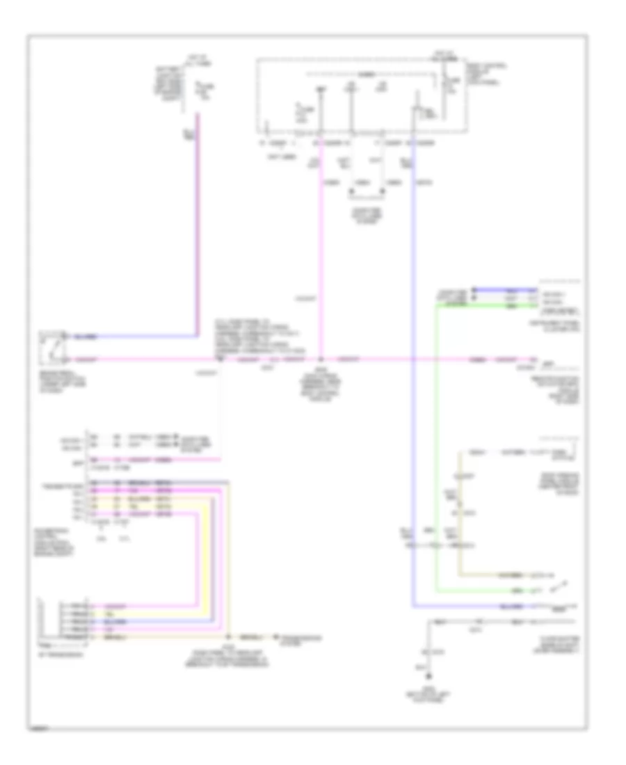
COOLING FAN
Cooling Fan Wiring Diagram (1 of 2) for Lincoln MKS EcoBoost 2013
List of elements for Cooling Fan Wiring Diagram (1 of 2) for Lincoln MKS EcoBoost 2013:
- (behind center of front fascia) (3.7l) active grille shutter (ags)
- 3.5l
- 3.7l
- Battery junction box (bjb) (left side of engine compt)
- C1381b
- C1381e
- C175b
- C175e
- Cec07
- Cec08
- Cht
- Computer data lines system
- Fuse 15a
- Fuse 40a
- G100 (right side of engine compt)
- Gnd
- Hfc
- Hot at all times
- Hot w/ pcm power relay energized
- Hs can +
- Hs can -
- Lfc
- Lin
- Powertrain control module (pcm) (right rear of engine compt)
- Re405
- S122
- Sig rtn
- Vdb04
- Vdb05
- Vdn06
- Ve712
- Vpwr
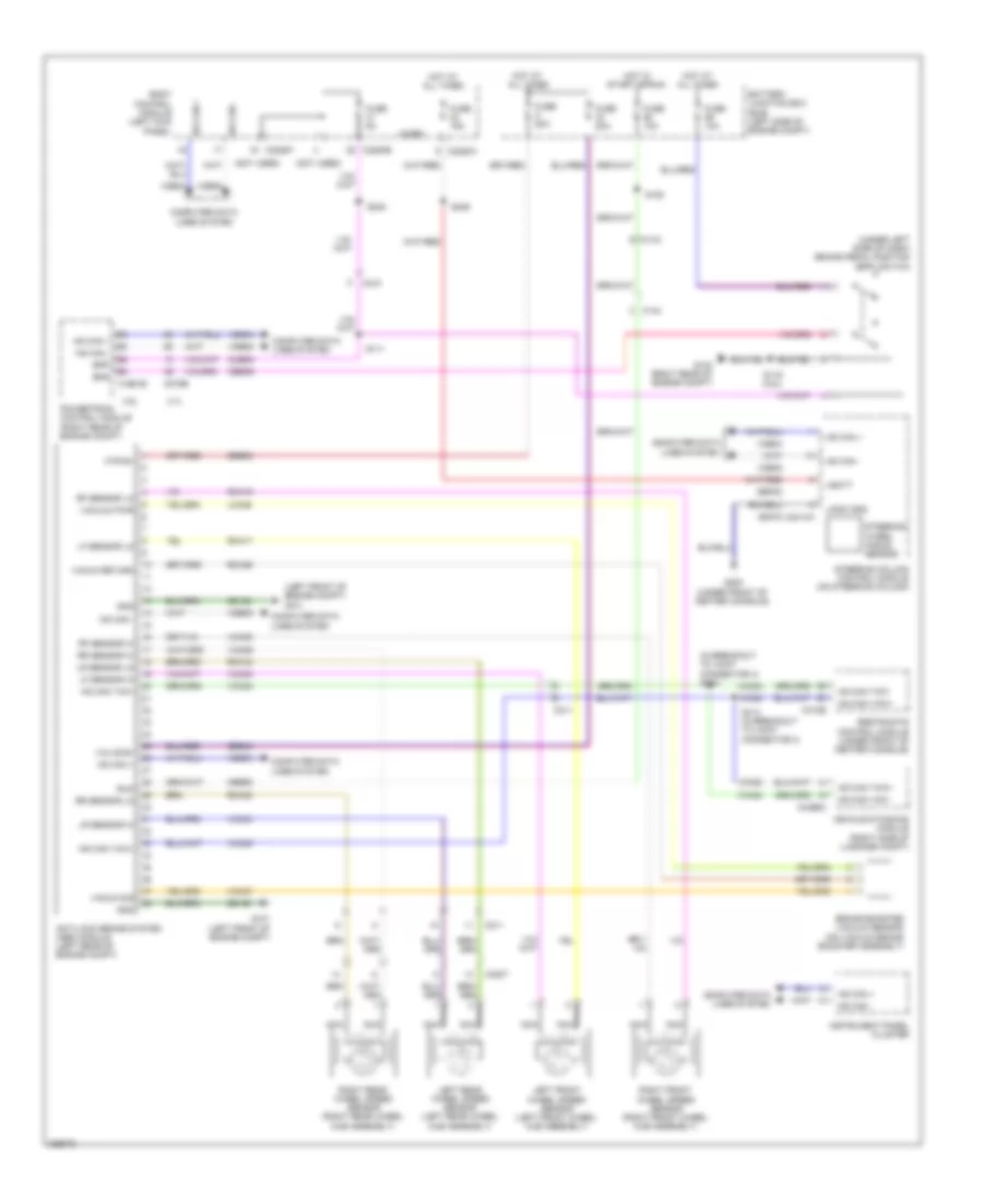
Cooling Fan Wiring Diagram (2 of 2) for Lincoln MKS EcoBoost 2013
List of elements for Cooling Fan Wiring Diagram (2 of 2) for Lincoln MKS EcoBoost 2013:
- 3.7l
- Battery junction box (bjb) (left side of engine compt)
- C192
- Cylinder head temperature (cht) sensor (3.5l: middle of right cylinder head) (3.7l: front of right cylinder head)
- Engine controls system
- Engine cooling fan motor 1 (behind left side of radiator)
- Engine cooling fan motor 2 (behind right side of radiator)
- Engine cooling fan relay hcf 1
- Engine cooling fan relay hcf 2
- Engine cooling fan relay lfc
- Fuse 25a
- G100 (right side of engine compt)
- G101 (left front of engine compt)
- S155 (dash panel to headlamp wiring harness)
CRUISE CONTROL
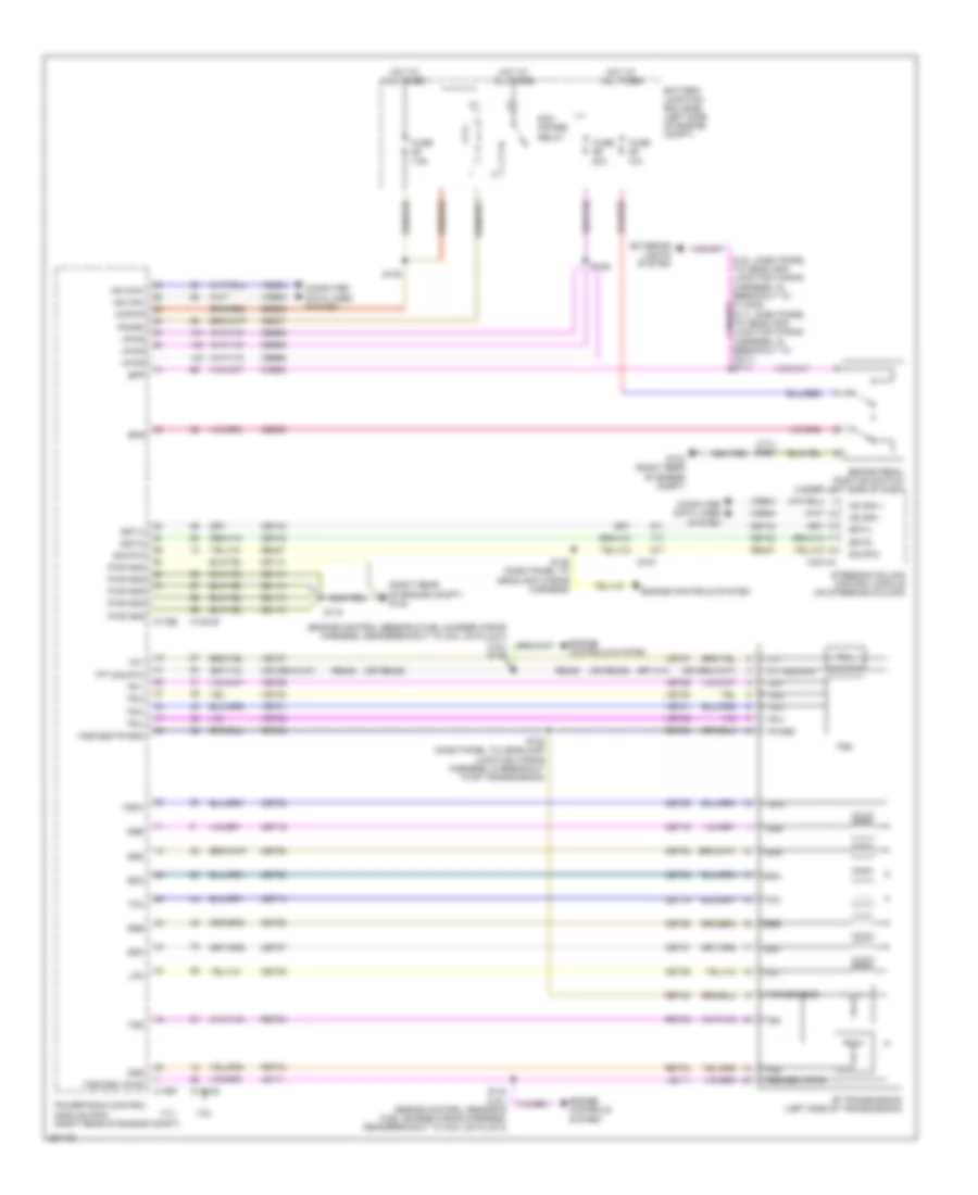
Cruise Control Wiring Diagram for Lincoln MKS EcoBoost 2013
List of elements for Cruise Control Wiring Diagram for Lincoln MKS EcoBoost 2013:
- (3.5l: dash panel to headlamp junction wiring harness, in breakout to c1100a) (3.7l: dash panel to headlamp junction wiring harness, in breakout to c211)
- (dash panel to headlamp junction wiring harness, in breakout to 6f transmission)
- (engine control sensor & fuel charge wiring harness, near breakout to coil on plug 3)
- (steering column) clockspring
- (under front of center console) g200
- (under left side of dash) brake pedal position (bpp) switch
- 3.5l
- 3.7l
- 6f transmission (left side of transmission)
- A/d 2
- A/d 4
- Accelerator pedal position (app) sensor (under left side of dash)
- App1
- App2
- Apprtn1
- Apprtn2
- Appverf2
- Appvref1
- Battery junction box (bjb) (left side of engine compt)
- Body control module (bcm) (left kick panel)
- Bpp
- Bps
- C1381b
- C1381e
- C1609a
- C1609b
- C175b
- C175e
- C175t
- C210
- C2153c
- C2153e
- C218b
- C218c
- C2280a
- C2414a
- Cbb91
- Ccb08
- Ce412
- Ce426
- Ces09
- Cncl
- Computer data lines system
- Cruise control module (w/ adaptive cruise control) (left front of engine compt)
- Electronic throttle control (etc) (3.5l: top front of engine) (3.7l: top rear of engine)
- Engine controls system
- Etcref
- Etcrtn
- Exterior lights system
- Fuse 10a
- Fuse 15a
- Fuse 5a
- G101 (left front of engine compt)
- G102 (right rear of engine compt)
- Gd113
- Gd120
- Gd375
- Gnd
- Hot at all times
- Hot in start or run
- Hs can +
- Hs can -
- Hs can+
- Hs can-
- Instrument panel cluster (ipc)
- Interior lights system
- Isp-r
- Le111
- Le134
- Le136
- Le137
- Left steering wheel switch
- Logic gnd
- Lt sw gnd
- Ms can+
- Ms can-
- Nca
- Off/ gap-
- On/ gap+
- Oss
- Powertrain control module (pcm) (right rear of engine compt)
- Pwrgnd
- Re134
- Re136
- Re137
- Remote function actuator (rfa) module (right side of dash)
- Res
- Ret04
- Ret24
- Ret33
- Right steering wheel switch
- S100
- S111
- S116
- S116 (3.7l)
- S142
- S245 (main wiring harness, near breakout to body control module)
- S246
- S295 (in steering wheel)
- S296 (in steering wheel)
- Sbb79
- Sbp23
- Set+
- Set-
- Steering column control module (sccm) (on steering column)
- Tacm+
- Tacm-
- Tp1
- Tp2
- Tss
- Tss/oss gnd
- Tss/oss/tr gnd
- Tss/oss/vpwr
- Vbatt
- Vdb04
- Vdb05
- Vdb06
- Vdb07
- Ve701
- Ve702
- Ve818
- Ve819
- Vpwr
DEFOGGERS
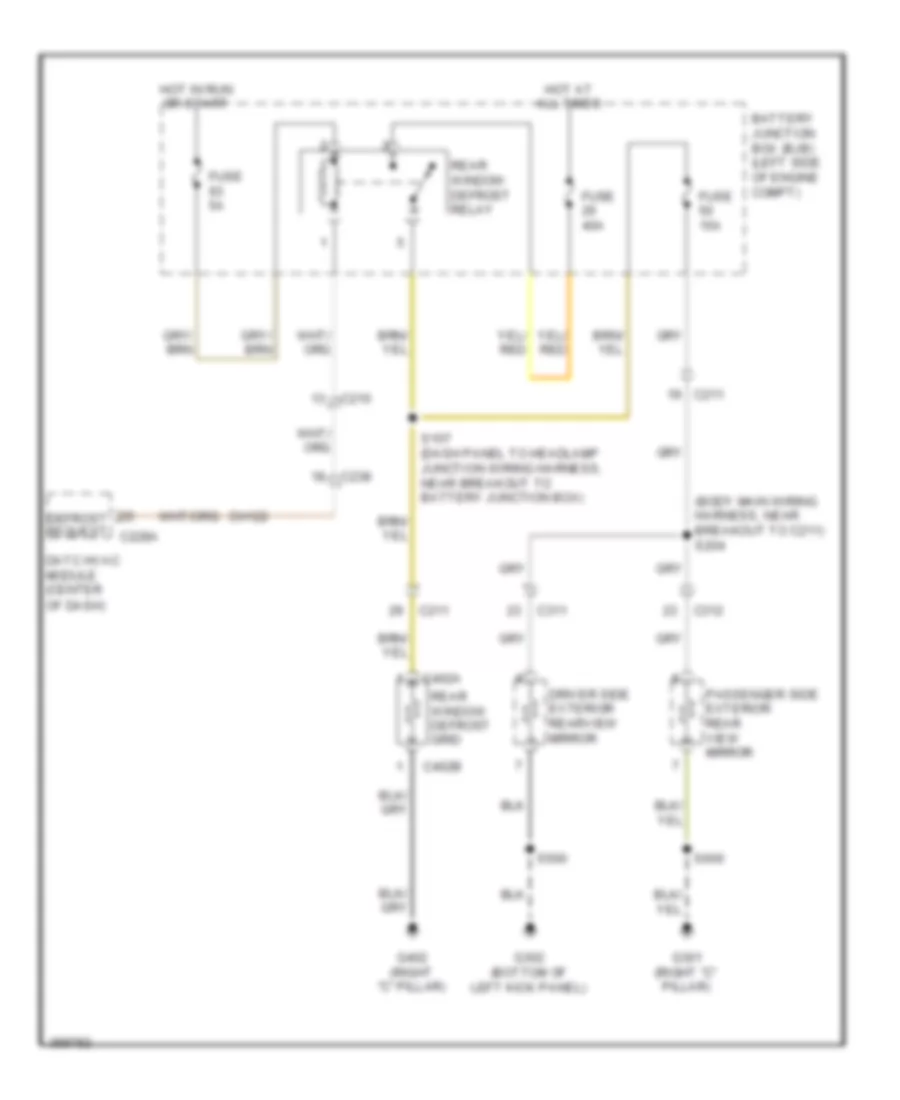
Defoggers Wiring Diagram for Lincoln MKS EcoBoost 2013
List of elements for Defoggers Wiring Diagram for Lincoln MKS EcoBoost 2013:
- (body main wiring harness, near breakout to c211) s204
- Battery junction box (bjb) (left side of engine compt)
- C210
- C211
- C238
- C311
- C312
- C402a
- C402b
- Ch122
- Datc hvac module (center
- Defrost request c228a
- Driver side exterior rearview mirror
- Fuse 15a
- Fuse 40a
- Fuse 5a
- G301 (right "c" pillar)
- G302 (bottom of left kick panel)
- G402 (right "c" pillar)
- Hot at all times
- Hot in run or start
- Of dash)
- Passenger side exterior rear view mirror
- Rear window defrost grid
- Rear window defrost relay
- S107 (dash panel to headlamp junction wiring harness, near breakout to battery junction box)
- S500
- S600
ELECTRONIC POWER STEERING
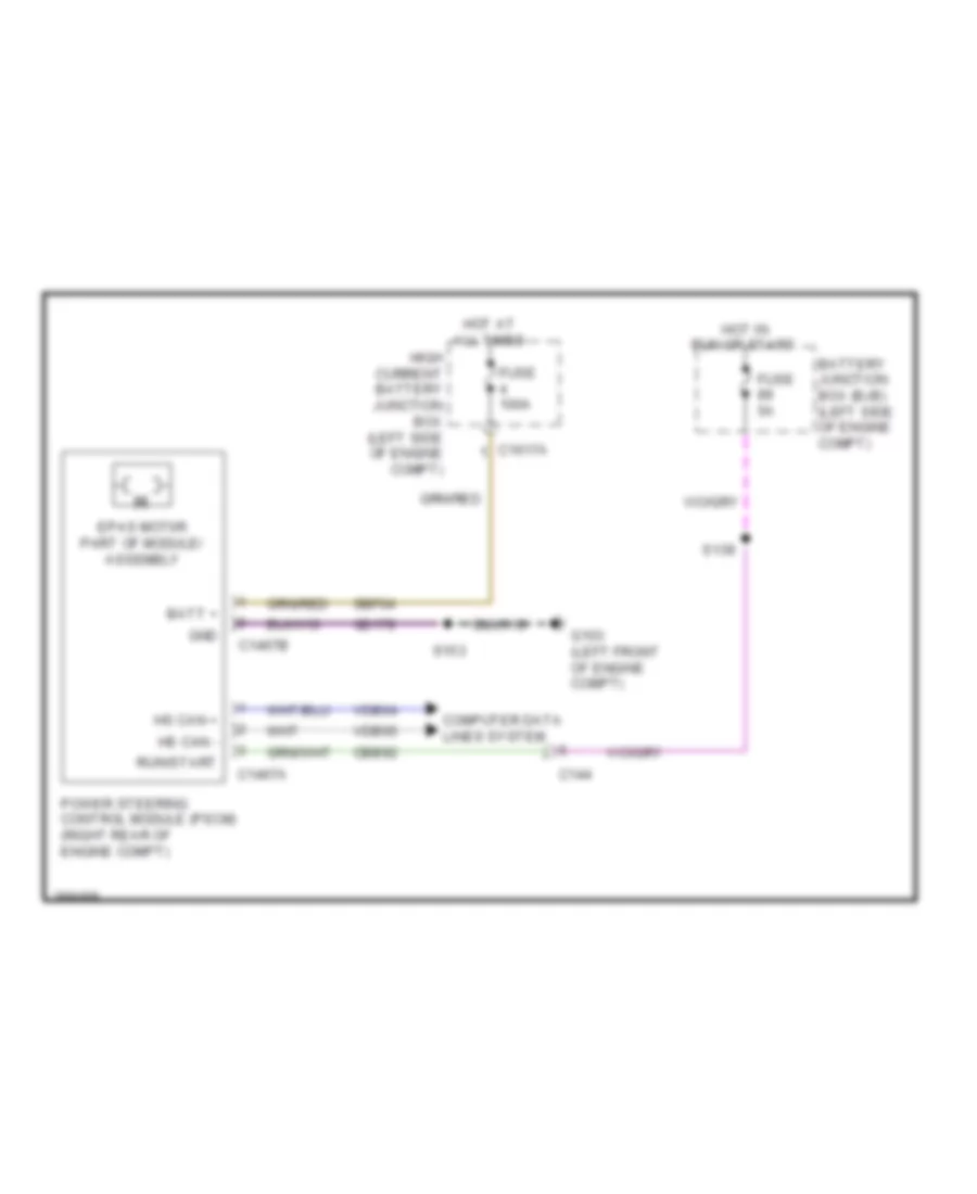
Electronic Power Steering Wiring Diagram for Lincoln MKS EcoBoost 2013
List of elements for Electronic Power Steering Wiring Diagram for Lincoln MKS EcoBoost 2013:
- Batt +
- Battery junction box (bjb) (left side of engine compt)
- C144
- C1467a
- C1467b
- C1617a
- Cbb92
- Computer data lines system
- Epas mot0r part of module/ assembly
- Fuse 100a
- Fuse 5a
- G103 (left front of engine compt)
- Gd178
- Gnd
- High current battery junction box (left side of engine compt)
- Hot at all times
- Hot in run or start
- Hs can +
- Hs can -
- Power steering control module (pscm) (right rear of engine compt)
- Run/start
- S139
- S153
- Sbf04
- Vdb04
- Vdb05
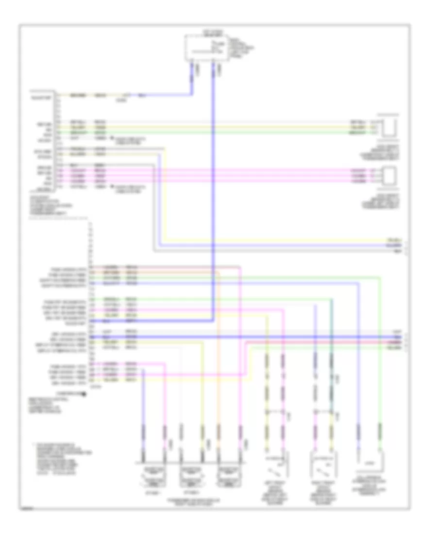
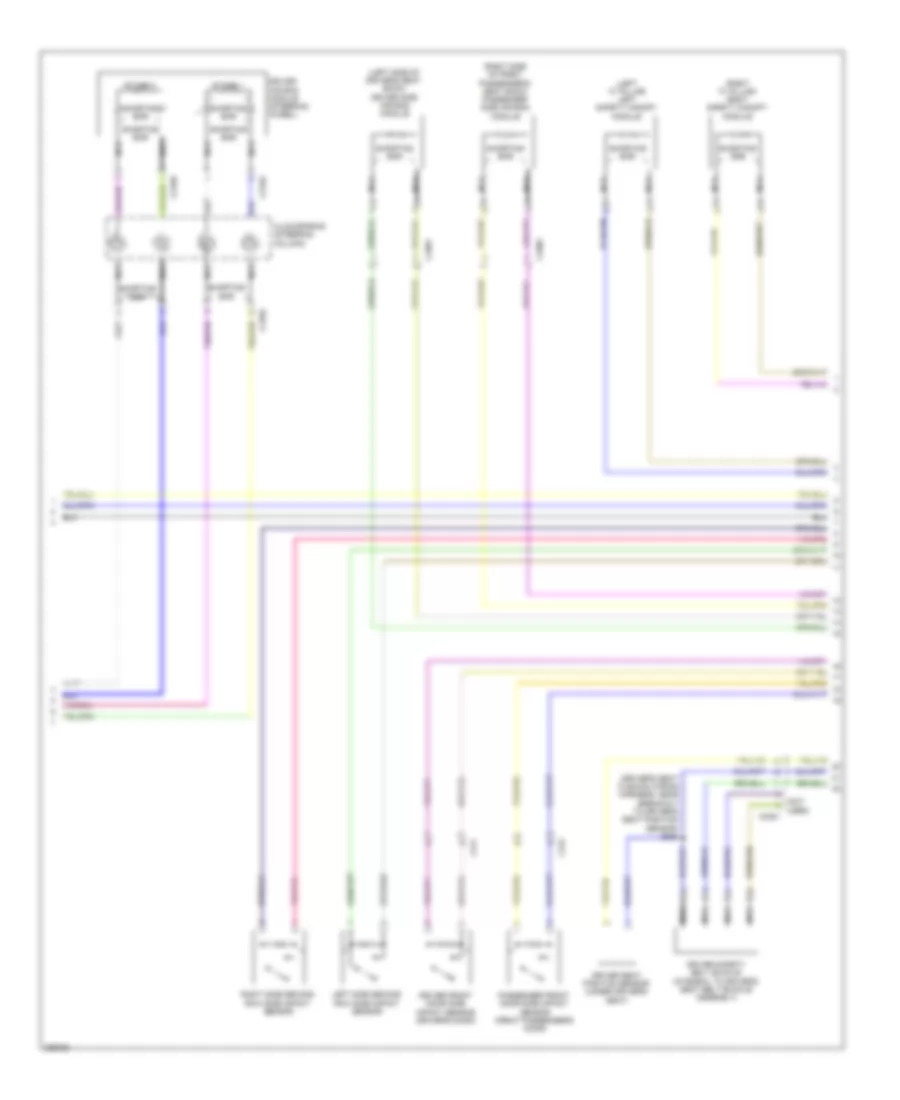
ELECTRONIC SUSPENSION
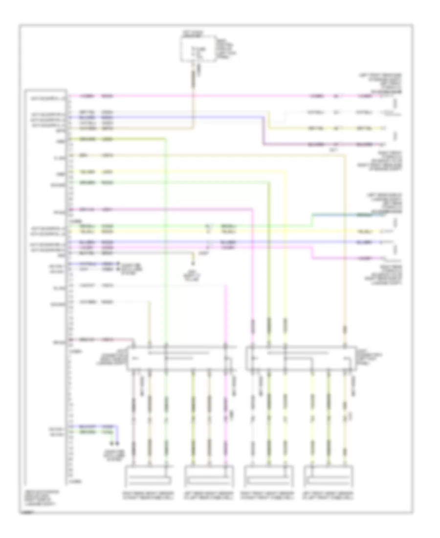
Electronic Suspension Wiring Diagram for Lincoln MKS EcoBoost 2013
List of elements for Electronic Suspension Wiring Diagram for Lincoln MKS EcoBoost 2013:
- (left front rear side of engine compt) left front hydraulic solenoid valve
- (left rear side of luggage compt) left rear hydraulic solenoid valve
- (not used)
- Active dmpr fl hi
- Active dmpr fl lo
- Active dmpr fr hi
- Active dmpr fr lo
- Active dmpr rl hi
- Active dmpr rl lo
- Active dmpr rr hi
- Active dmpr rr lo
- Body control module (left kick panel)
- C211
- C2280d
- C3007
- C4396a
- C4396b
- C4396c
- Cbp33
- Ccd03
- Ccd04
- Ccd05
- Ccd06
- Computer data lines system
- Fl sig
- Fr sig
- Fuse 10a
- G301 (right "c" pillar)
- Gd348
- Gnd
- Hot in run or start
- Hs can +
- Hs can -
- Isp-r
- Joint connector 3 (right side of luggage compt)
- Joint connector 9 (left kick panel)
- Lcd02
- Lcd23
- Left front height sensor (in left front wheelwell)
- Left rear height sensor (in left rear wheelwell)
- Rcd02
- Rcd03
- Rcd04
- Rcd05
- Rcd06
- Rcd23
- Right front height sensor (in right front wheelwell)
- Right front hydraulic solenoid valve (right front rear side of engine compt)
- Right rear height sensor (in right rear wheelwell)
- Right rear hydraulic solenoid valve (right rear side of luggage compt)
- Rl sig
- Rr sig
- Sig gnd
- Vca23
- Vca24
- Vcd10
- Vcd11
- Vcd12
- Vcd13
- Vdb04
- Vdb05
- Vehicle dynamics module (vdm) (right side of luggage compt)
- Vref
ENGINE PERFORMANCE
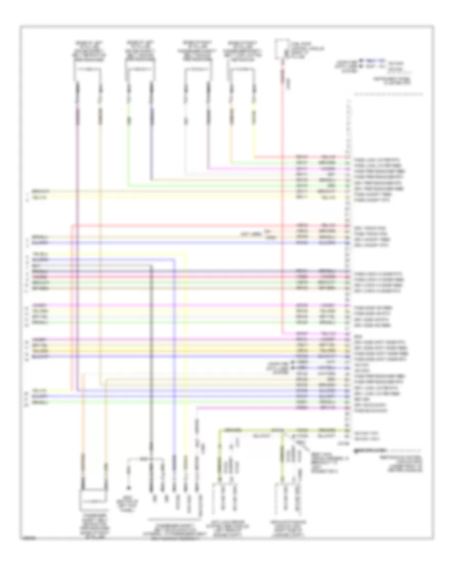
3.5L TWIN TURBO
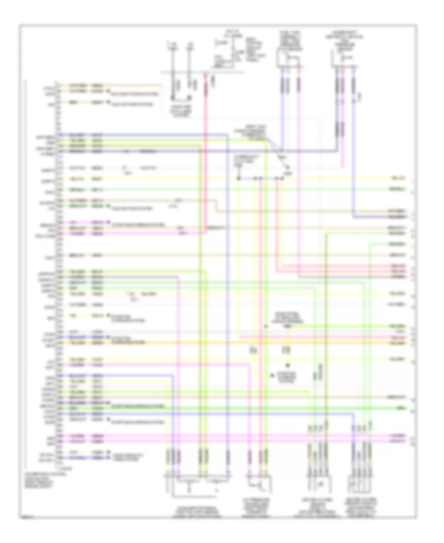
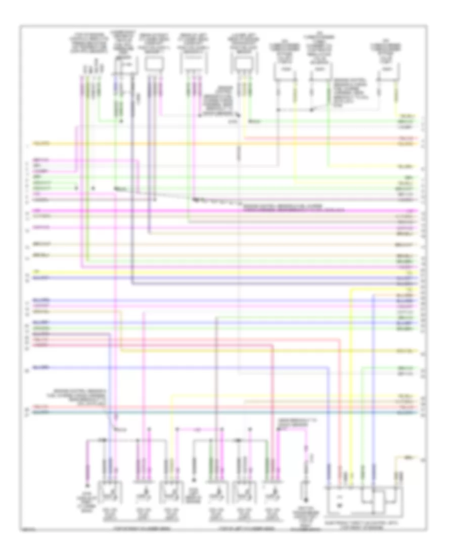
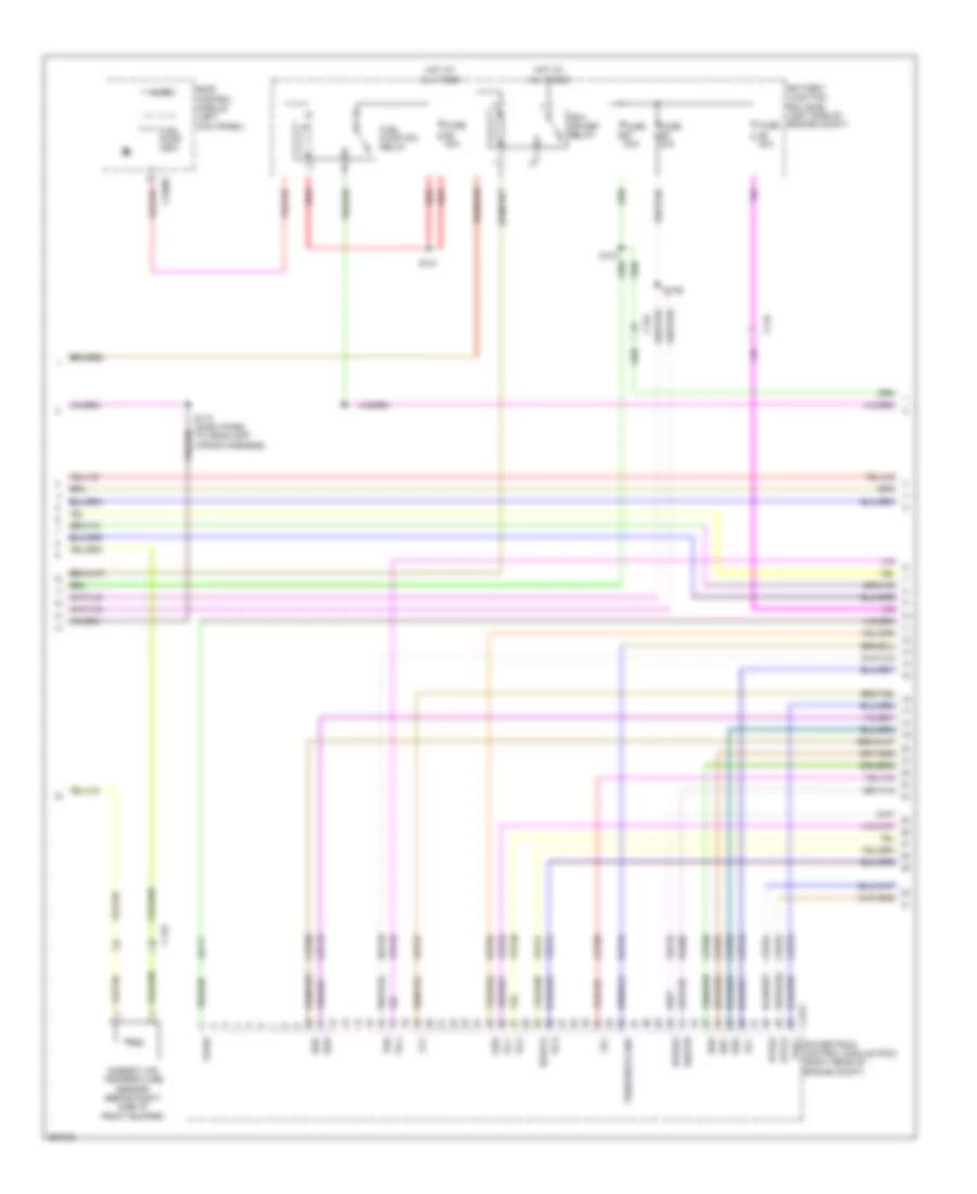
3.5L Twin Turbo, Engine Performance Wiring Diagram (1 of 6) for Lincoln MKS EcoBoost 2013
List of elements for 3.5L Twin Turbo, Engine Performance Wiring Diagram (1 of 6) for Lincoln MKS EcoBoost 2013:
- (body main wiring harness, in breakout to c3047)
- (dash panel to headlamp wiring harness) s144
- (fuel tank assembly) fuel tank pressure (ftp) sensor
- (in breakout to c1100d) s125
- (under right center of vehicle) fuel pressure sensor
- A/c pressure transducer (right front corner of engine compt)
- Aat
- Accelerator pedal position (app) sensor (under left side of dash)
- Accr
- Acpt
- Air conditioning system
- App1
- App2
- Apprtn1
- Apprtn2
- Appvref1
- Appvref2
- Awdc
- Awdm
- Body control module (bcm) (left kick panel)
- Bpp
- Bps
- C134
- C1381b
- C144
- C211
- C2280f
- C315
- Cact
- Canv
- Cbb90
- Ccb08
- Cdc10
- Cdc12
- Cdc15
- Cdc35
- Ce113
- Ce114
- Ce233
- Ce234
- Ce237
- Ce336
- Ce436
- Cec07
- Cec08
- Ces09
- Ch302
- Computer data lines system
- Cooling fans system
- Evapcp
- Evdc
- Fpc
- Fpm
- Ftpref
- Fuse 10a
- Gencom
- Genmon
- Heated oxygen sensor (ho2s) 12 (downstream from catalytic converter 1)
- Heated oxygen sensor (ho2s) 22 (downstream from catalytic converter 2)
- Hfc
- Ho2s12
- Ho2s22
- Hot at all times
- Hs can +
- Hs can -
- Hs can+
- Hs can-
- Htr12
- Htr22
- Isp-r
- Le136
- Le137
- Le230
- Le424
- Lfc
- Micro
- Pcm wake
- Pcm wake up (fet)
- Pcmrc
- Powertrain control module (pcm) (right rear of engine compt)
- Re136
- Re137
- Re230
- Re242
- Re249
- Re407
- S360
- S361
- Sigrtn
- Smc
- Smcs
- Start
- Starting/ charging system
- Starting/charging system
- Vcf34
- Vcf35
- Vdb04
- Vdb05
- Ve225
- Ve462
- Ve518
- Ve701
- Ve702
- Ve731
- Ve733
- Ve751
- Vh407
- Vh433
- Vref
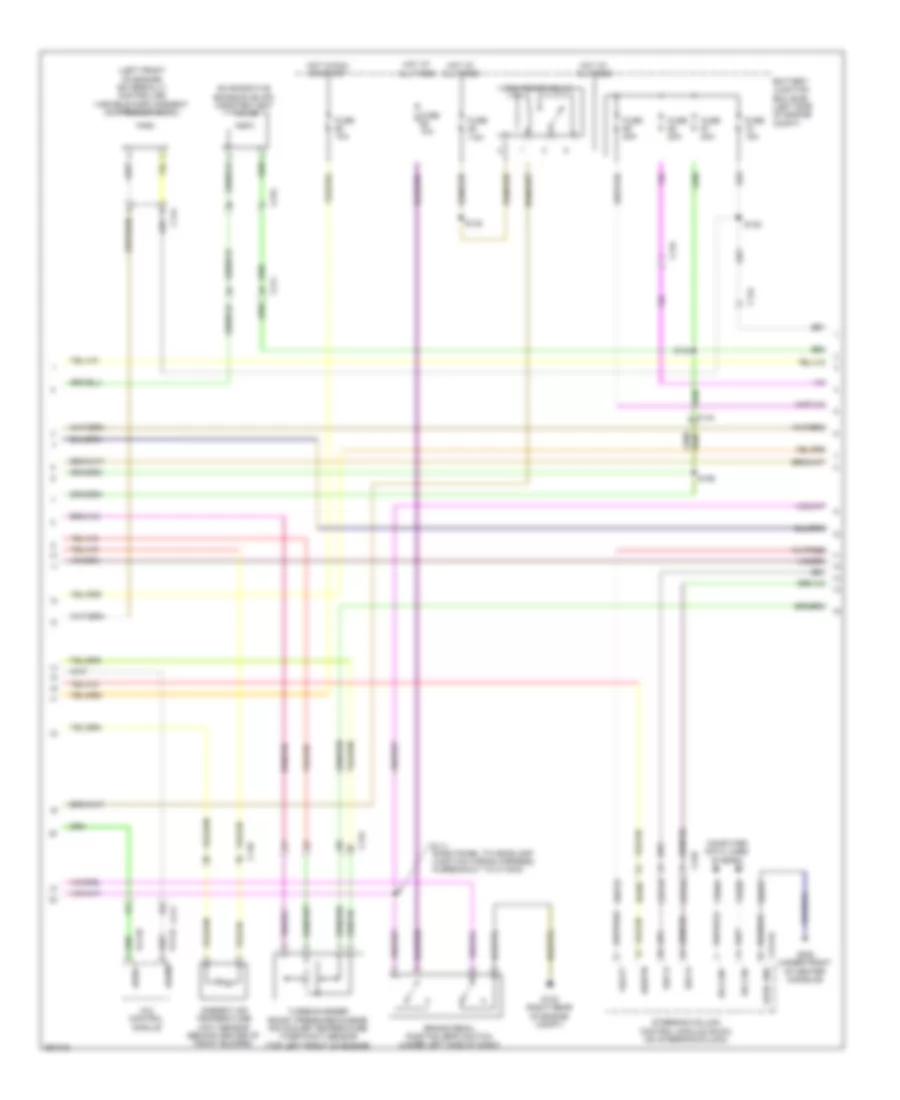
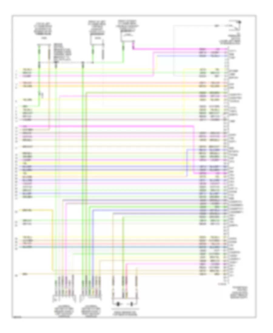
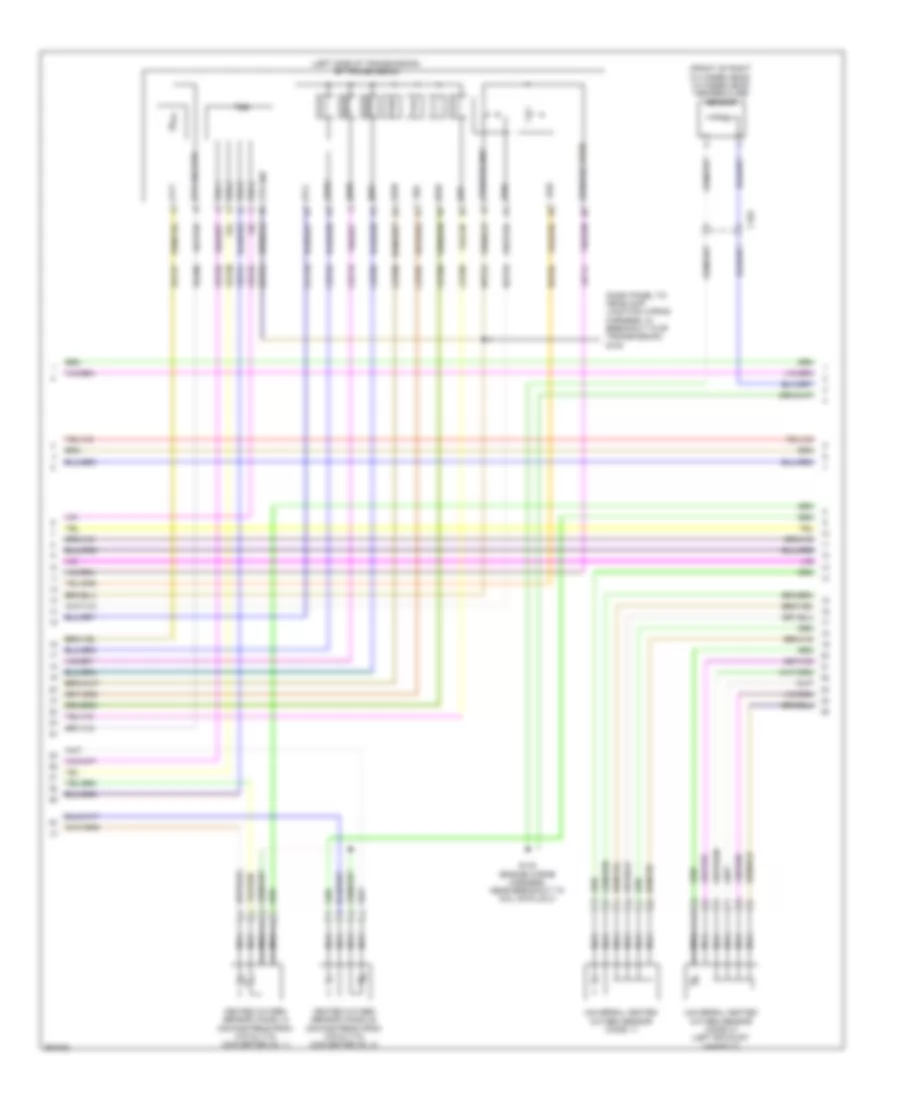
3.5L Twin Turbo, Engine Performance Wiring Diagram (2 of 6) for Lincoln MKS EcoBoost 2013
List of elements for 3.5L Twin Turbo, Engine Performance Wiring Diagram (2 of 6) for Lincoln MKS EcoBoost 2013:
- (dash panel to headlamp junction wiring harness, in breakout to c1100a)
- (left front of engine) externally controlled variable displacement compressor (evdc)
- 4x4 control module
- 7.5a
- Ambient air temperature (aat) sensor (behind center of front bumper)
- Awdc
- Awdm
- Battery junction box (bjb) (left side of engine compt)
- Brake pedal position (bpp) switch (under left side of dash)
- C110
- C134
- C144
- C210
- C211
- C2414a
- C315
- Cet42
- Cet43
- Computer data lines system
- Evaporative emission (evap) canister vent valve
- Fuse
- Fuse 10a
- Fuse 15a
- Fuse 20a
- G102 (right rear of engine compt)
- G200 (under front of center console)
- Gd375
- Hot at all times
- Hot in run or start
- Hs can+
- Hs can-
- Logic gnd
- Pcm power relay
- Re407
- S111
- S122
- S134
- S135
- S168
- Sbp23
- Sigrtn
- Sst-d
- Sst-u
- Steering column control module (sccm) (on steering column)
- Turbocharger boost pressure/charge air cooler temperature (tcbp/cact) sensor (top left front of engine)
- Vbatt
- Vcf34
- Vcf35
- Vdb04
- Vdb05
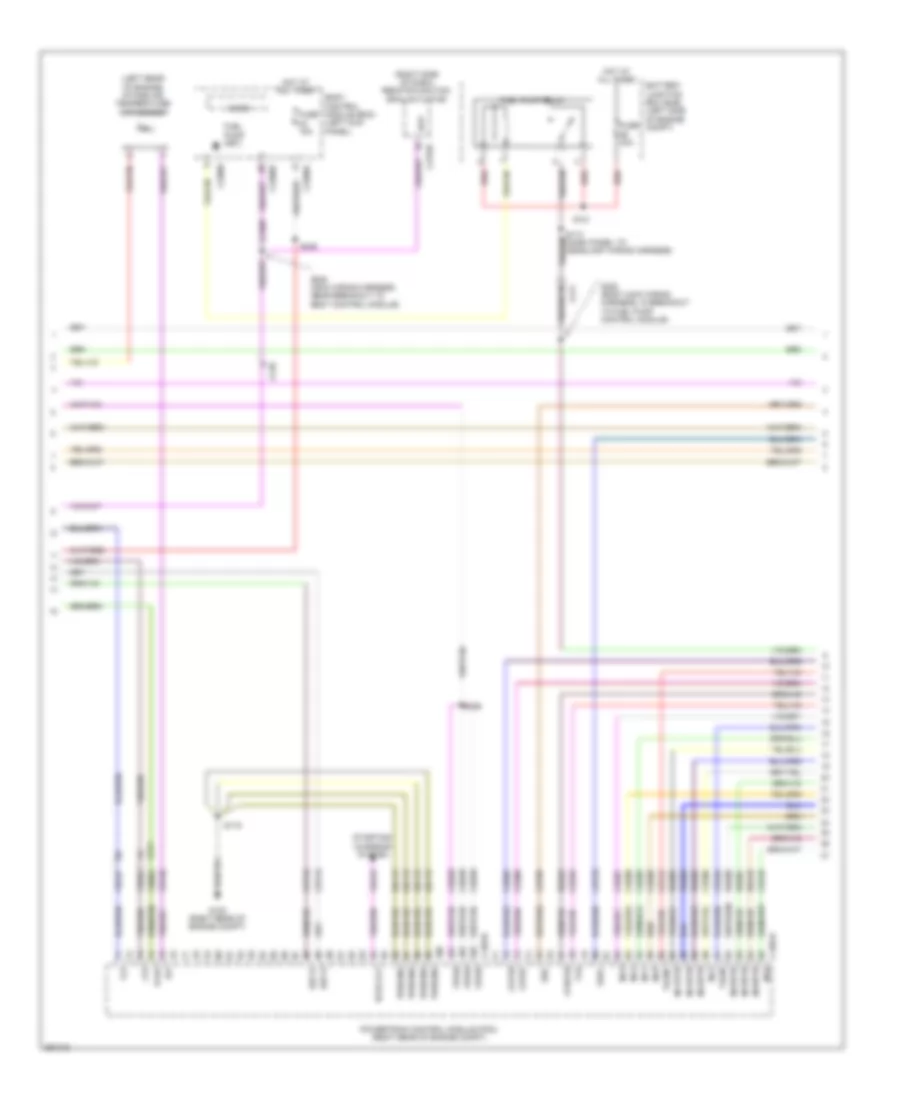
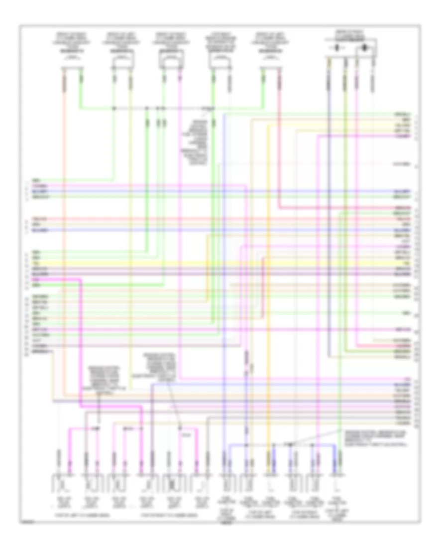
3.5L Twin Turbo, Engine Performance Wiring Diagram (3 of 6) for Lincoln MKS EcoBoost 2013
List of elements for 3.5L Twin Turbo, Engine Performance Wiring Diagram (3 of 6) for Lincoln MKS EcoBoost 2013:
- (left rear of engine) intake air temperature (iat) sensor
- (right side of dash) remote function (rfa) actuator
- Battery junction box (bjb) (left side of engine compt)
- Bcs2 alt
- Body control module (bcm) (left kick panel)
- Bpp
- C1381b
- C1381e
- C210
- C211
- C2153c
- C2280a
- C2280b
- C2280f
- Cbb69
- Ccb08
- Ce205
- Ce206
- Ce207
- Ce208
- Ce209
- Ce210
- Ce226
- Ce305
- Ce308
- Ce412
- Ce426
- Cet07
- Cet25
- Cet42
- Cet43
- Cop3e
- Cop6f
- Flp
- Ftp
- Fuel pump (fet)
- Fuel pump relay
- Fuse 15a
- Fuse 30a
- Fvr
- Fvrrtn
- G102 (right rear of engine compt)
- Gd113
- Hot at all times
- Iat
- Inj1
- Inj1rtn
- Inj2
- Inj2rtn
- Inj3
- Inj3rtn
- Inj4
- Inj4rtn
- Inj5
- Inj5rtn
- Inj6
- Inj6rtn
- Micro
- Powertrain control module (pcm) (right rear of engine compt)
- Pwrgnd
- Re205
- Re206
- Re207
- Re208
- Re209
- Re210
- Re226
- Red
- S110 (dash panel to headlamp wiring harness)
- S116
- S121
- S159
- S245 (main wiring harness, near breakout to body control module)
- S246
- S300 (body main wiring harness, in breakout to fuel pump control module)
- Ssc
- Sst-d
- Sst-u
- Starting/ charging system
- Tacm+
- Tacm-
- Tcbp
- Tspc
- Vdc61
- Ve727
- Ve740
- Ve804
- Ve922
- Vpwr
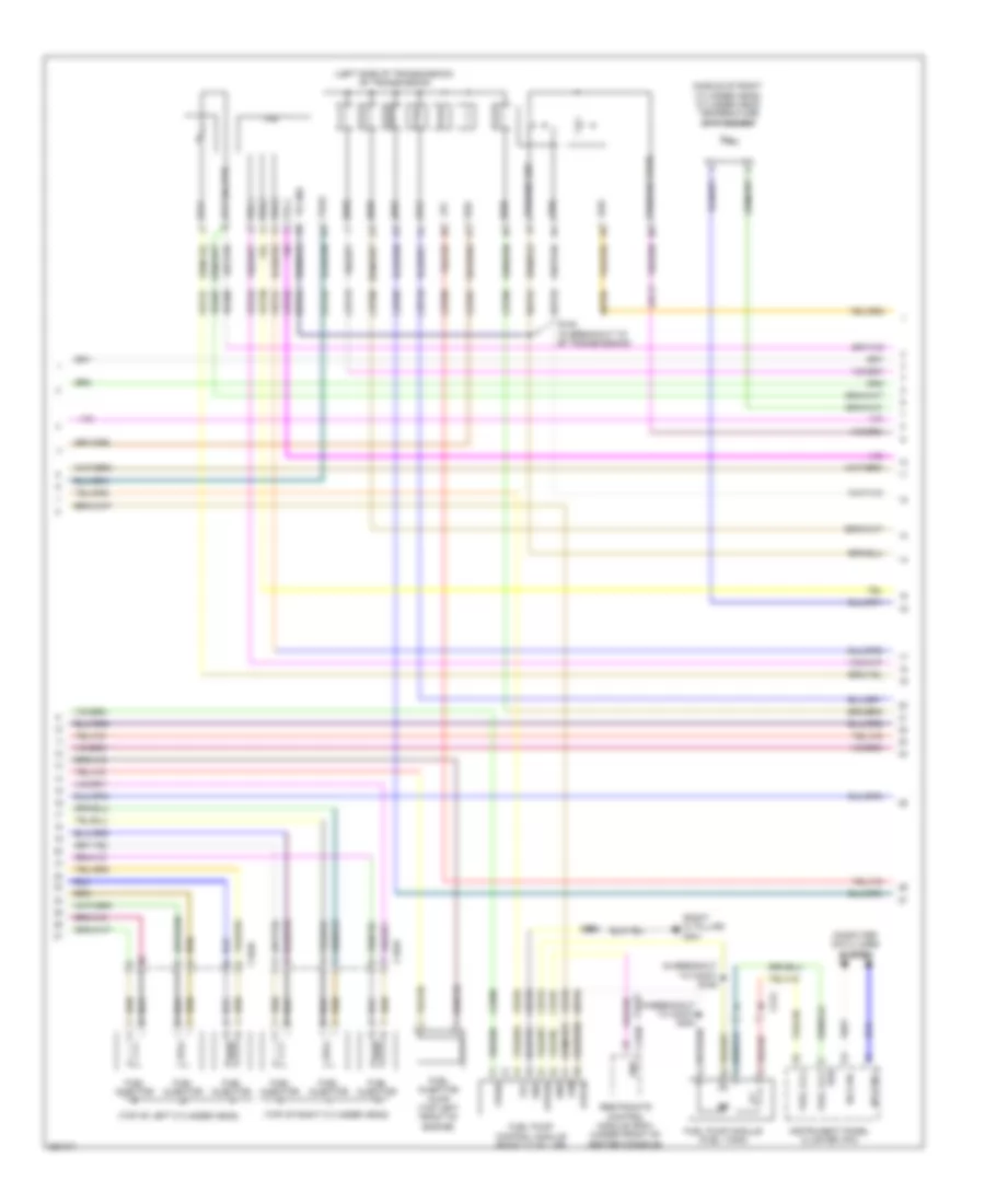
3.5L Twin Turbo, Engine Performance Wiring Diagram (4 of 6) for Lincoln MKS EcoBoost 2013
List of elements for 3.5L Twin Turbo, Engine Performance Wiring Diagram (4 of 6) for Lincoln MKS EcoBoost 2013:
- (in breakout to c3047) s339
- (in breakout to c3047) s354
- (left side of transmission) 6f transmission
- (middle of right cylinder head) cylinder head temperature (cht) sensor
- (right "c" pillar) g301
- (top of left cylinder head)
- (top of right cylinder head)
- C1045
- C1046
- C212
- C310b
- Ce515
- Ce608
- Cet05
- Cet06
- Cet07
- Cet08
- Cet09
- Cet10
- Cet19
- Cet25
- Computer data lines system
- Cr167
- Ens
- Fpc
- Fpm
- Fppwr
- Fprtn
- Fuel injection pump (top left front of engine)
- Fuel injector
- Fuel lvl1
- Fuel pump control module (right "c" pillar)
- Fuel pump module (fuel tank)
- Gd348
- Gnd
- Hs can +
- Hs can -
- Instrument panel cluster (ipc)
- Le111
- Lpc
- Oss
- Re405
- Re406
- Re515
- Restraints control module (rcm) (under front of center console)
- Ret04
- Ret24
- Ret33
- Rtn
- S100 (in breakout to 6f transmission)
- S338
- Ssa
- Ssb
- Ssc
- Ssd
- Sse
- Tcc
- Tft
- Tft sig rtn
- Tr gnd
- Tr-1
- Tr-2
- Tr-3
- Tr-4
- Trs
- Tspc
- Tss
- Tss/oss gnd
- Tss/oss vpwr
- Ve225
- Ve518
- Vet27
- Vet29
- Vet30
- Vet31
- Vet32
- Vpwr
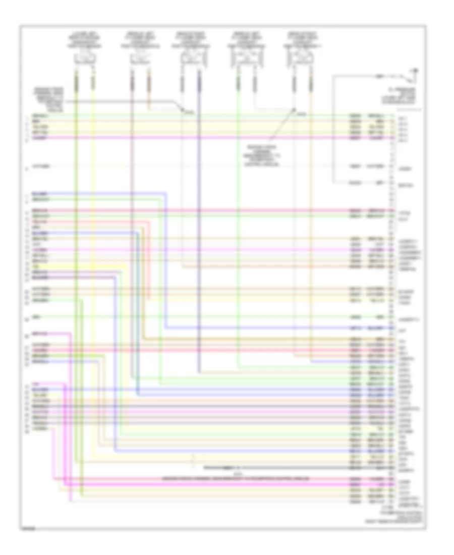
3.5L Twin Turbo, Engine Performance Wiring Diagram (5 of 6) for Lincoln MKS EcoBoost 2013
List of elements for 3.5L Twin Turbo, Engine Performance Wiring Diagram (5 of 6) for Lincoln MKS EcoBoost 2013:
- (engine control sensor & fuel charge wiring harness, near breakout to coil on plug 3)
- (engine control sensor & fuel charge wiring harness, near breakout to knock sensor)
- (engine control sensor & wiring fuel charge harness, near breakout to coil on plug 3) s150
- (lower left rear of engine) crankshaft position (ckp) sensor
- (near breakout to knock sensor) s147
- (on turbocharger) turbo- charger (tc) wastegate regulating valve solenoid
- (on turbocharger) turbocharger bypass valve (tcby)
- (on turbocharger) turbocharger bypass valve 2 (tcby2)
- (rear of left cylinder head) camshaft position (cmp21) sensor 21
- (rear of right cylinder head) camshaft position (cmp11) sensor 11
- (top of engine) manifold absolute pressure/intake air temperature (map/iat2) sensor 2
- (top of left cylinder head)
- (top of right cylinder head)
- (under right center of vehicle) fuel rail pressure (frp) sensor
- C1046
- C1609a
- C1609b
- C174
- Coil on plug (cop) 1
- Coil on plug (cop) 2
- Coil on plug (cop) 3
- Coil on plug (cop) 4
- Coil on plug (cop) 5
- Coil on plug (cop) 6
- Electronic throttle control (etc) (top front of engine)
- G106 (middle of right cylinder bank)
- G108 (left rear of engine)
- Iat2
- Ignition transformer capacitor 1 (top of right cylinder bank)
- Map
- S101
- S108
- S140
- S141
- S142
- S143
- S151
- Sig rtn
- Vref
3.5L Twin Turbo, Engine Performance Wiring Diagram (6 of 6) for Lincoln MKS EcoBoost 2013
List of elements for 3.5L Twin Turbo, Engine Performance Wiring Diagram (6 of 6) for Lincoln MKS EcoBoost 2013:
- (engine control sensor & fuel charge wiring harness, near breakout to coil on plug 3) s146
- (front of left cylinder head) variable camshaft timing (vct21) solenoid 21
- (front of right cylinder head) variable camshaft timing (vct11) solenoid 11
- (top of left cylinder bank) evaporative emission (evap) purge valve
- C134
- C1381e
- Ce235
- Ce236
- Ce303
- Ce304
- Ce306
- Ce307
- Ce421
- Ce422
- Ce435
- Cet05
- Cet06
- Cet08
- Cet09
- Cet10
- Cet19
- Cht
- Ckp
- Cmc24
- Cmp11
- Cmp21
- Cop 1a
- Cop2c
- Cop4b
- Cop5d
- Eop sw
- Etcref
- Etcrtn
- Frp
- Iat2
- Knock sensor (ks) (top rear of engine)
- Ks1 +
- Ks1 -
- Ks2 +
- Ks2 -
- Le111
- Le134
- Le423
- Le448
- Le449
- Le450
- Le451
- Le452
- Le453
- Lpc
- Map
- Oil pressure switch (lower left rear of engine block)
- Oss
- Powertrain control module (pcm) (right rear of engine compt)
- Re134
- Re323
- Re324
- Re405
- Re406
- Red
- Ret04
- Ret24
- Ret33
- Sigrtn
- Ssa
- Ssb
- Ssd
- Sse
- Tan
- Tcby
- Tcby2
- Tcc
- Tcwrvs
- Tft
- Tp 1
- Tp2
- Tr gnd
- Tr-1
- Tr-2
- Tr-3
- Tr-4
- Tss
- Universal heated oxygen sensor (ho2s) 11 (right exhaust manifold)
- Universal heated oxygen sensor (ho2s) 21 (left exhaust manifold)
- Uo2s11
- Uo2s21
- Uo2sgref11
- Uo2sgref21
- Uo2shtr11
- Uo2shtr21
- Uo2spc11
- Uo2spc21
- Uo2spct21
- Uo2ssptc11
- Vct11
- Vct21
- Ve706
- Ve707
- Ve711
- Ve712
- Ve727
- Ve740
- Ve801
- Ve802
- Ve804
- Ve818
- Ve819
- Ve824
- Ve826
- Ve827
- Vet27
- Vet29
- Vet30
- Vet31
- Vet32
- Vref
3.7L
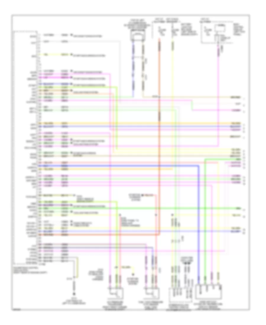
3.7L, Engine Performance Wiring Diagram (1 of 6) for Lincoln MKS EcoBoost 2013
List of elements for 3.7L, Engine Performance Wiring Diagram (1 of 6) for Lincoln MKS EcoBoost 2013:
- (top of left cylinder bank) evaporative emission (evap) canister vent valve
- A/c pressure transducer (right front corner of engine compt)
- Aat
- Accr
- Acpt
- Air conditioning system
- App1
- App2
- Apprtn 1
- Apprtn2
- Appvref
- Apvref2
- Awdc
- Battery junction box (bjb) (left side of engine compt)
- Bcs2alt
- Body control module (left kick panel)
- Bpp
- Bps
- C175b
- C210
- C211
- C2280f
- C2414a
- C315
- Canv
- Cbb69
- Cbb90
- Ccb08
- Cdc10
- Cdc12
- Cdc15
- Cdc35
- Cdc54
- Ce114
- Ce237
- Ce436
- Ce509
- Ce608
- Cec07
- Cec08
- Cet42
- Cet43
- Ch302
- Computer data lines system
- Cooling fans system
- Evdc
- Fpc
- Fpm
- Ftp
- Ftpref
- Fuel tank pressure (ftp) sensor (fuel tank assembly)
- Fuse 10a
- Fuse 7.5a
- G102 (right rear of engine compt)
- G110 (top front of left cylinder bank)
- Gd113
- Gencom
- Genmon
- Hfc
- Hot at all times
- Hot in run or start
- Hs can +
- Hs can -
- Iat
- Injpwrm
- Ispr
- Kapwr
- Le136
- Le137
- Le230
- Le424
- Lfc
- Lin
- Maf
- Mafrtn
- Mass air flow/ intake air temperature (maf/iat) sensor (left rear of engine)
- Micro
- Pcm wake
- Pcm wake up (fet)
- Pcmr
- Powertrain control module (pcm) (right rear of engine compt)
- Pwr gnd
- Re136
- Re137
- Re320
- Re407
- S116
- S125 (dash panel to headlamp wiring harness)
- S135
- S144 (dash panel to headlamp wiring harness)
- Sbb86
- Sigrtn
- Smc
- Smcs
- Sst-d
- Sst-u
- Start
- Starting/ charging system
- Starting/charging system
- Steering column control module (on steering column)
- Vcf34
- Vcf35
- Vdb04
- Vdb05
- Vdc61
- Vdn06
- Ve225
- Ve462
- Ve518
- Ve701
- Ve702
- Ve740
- Ve807
- Ve922
- Vh407
- Vh433
- Vpwr
- Vref
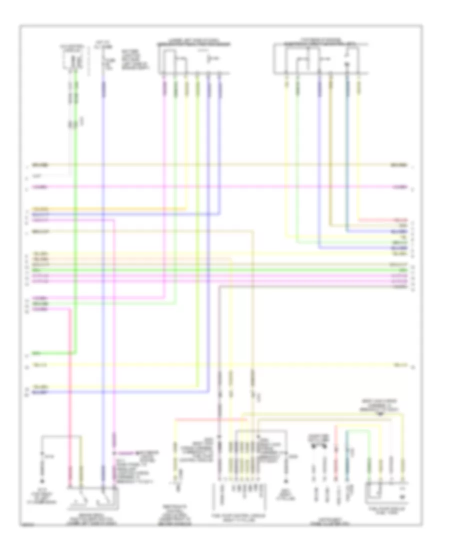
3.7L, Engine Performance Wiring Diagram (2 of 6) for Lincoln MKS EcoBoost 2013
List of elements for 3.7L, Engine Performance Wiring Diagram (2 of 6) for Lincoln MKS EcoBoost 2013:
- (body main wiring harness, in breakout to c3047) s339
- (top rear of engine) electronic throttle control (etc)
- (under left side of dash) accelerator pedal position sensor
- 1 rtn
- 4x4 control module
- Awdc
- Awdm
- Battery junction box (bjb) (left side of engine compt)
- Brake pedal position (bpp) switch (under left side of dash)
- C211
- C212
- C310b
- Ce515
- Ce608
- Computer data lines system
- Cr167
- Ens
- Exterior lights system
- Fp pwr
- Fp rtn
- Fpc
- Fpm
- Fuel lvl
- Fuel lvl 1
- Fuel pump control module (right "c" pillar)
- Fuel pump module (fuel tank)
- Fuse 10a
- G110 (top front of left cylinder bank)
- G301 (right "c" pillar)
- Gd348
- Gnd
- Hot at all times
- Hs can +
- Hs can -
- Instrument panel cluster (ipc)
- Restraints control module (rcm) (under front of center console)
- S116
- S300 (body main wiring harness, in breakout to fuel pump control module)
- S338
- S354 (body main wiring harness, in re515 breakout to c3047)
- Vcf34
- Vcf35
- Ve225
- Ve518
- Vpwr fuel
3.7L, Engine Performance Wiring Diagram (3 of 6) for Lincoln MKS EcoBoost 2013
List of elements for 3.7L, Engine Performance Wiring Diagram (3 of 6) for Lincoln MKS EcoBoost 2013:
- Ambient air temperature sensor (behind right side of front bumper)
- Battery junction box (bjb) (left side of engine compt)
- Body control module (left kick panel)
- C110
- C134
- C175t
- C2280f
- Ce233
- Ce234
- Cet05
- Cet06
- Cet07
- Cet08
- Cet09
- Cet10
- Cet19
- Cet25
- Fuel pump (fet)
- Fuel pump (fp) relay
- Fuse 20a
- Fuse 30a
- Ho2s12
- Ho2s22
- Hot at all times
- Htr12
- Htr22
- Le111
- Lpc
- Micro
- Oss
- Pcm power relay
- Powertrain control module (pcm) (right rear of engine compt)
- Re406
- Red
- Ret04
- Ret24
- Ret33
- S110 (dash panel to headlamp wiring harness)
- S121
- S134
- S159
- Sigrtn
- Ssa
- Ssb
- Ssc
- Ssd
- Sse
- Tcc
- Tft
- Tr-1
- Tr-2
- Tr-3
- Tr-4
- Tspc
- Tss
- Tss/oss/tr gnd
- Ve731
- Ve733
- Vet27
- Vet29
- Vet30
- Vet31
- Vet32
- Vpwr
3.7L, Engine Performance Wiring Diagram (4 of 6) for Lincoln MKS EcoBoost 2013
List of elements for 3.7L, Engine Performance Wiring Diagram (4 of 6) for Lincoln MKS EcoBoost 2013:
- (dash panel to headlamp junction wiring harness, in breakout to 6f transmission) s100
- (front of right cylinder head) cylinder head temperature sensor
- (left side of transmission) 6f transmission
- C192
- Cet05
- Cet06
- Cet07
- Cet08
- Cet09
- Cet10
- Cet19
- Cet25
- Heated oxygen sensor (ho2s) 12 (downstream from catalytic converter no. 1)
- Heated oxygen sensor (ho2s) 22 (downstream from catalytic converter no. 2)
- Le111
- Lpc
- Nca
- Oss
- Re406
- Ret04
- Ret24
- Ret33
- S143 (engine wiring harness, near breakout to coil on plug 3)
- Ssa
- Ssb
- Ssc
- Ssd
- Sse
- Tcc
- Tft
- Tft sig rtn
- Tr gnd
- Tr-1
- Tr-2
- Tr-3
- Tr-4
- Trs
- Tspc
- Tss
- Tss/oss gnd
- Tss/oss vpwr
- Universal heated oxygen sensor (ho2s) 11
- Universal heated oxygen sensor (ho2s) 21 (left exhaust manifold)
- Vet27
- Vet29
- Vet30
- Vet31
- Vet32
3.7L, Engine Performance Wiring Diagram (5 of 6) for Lincoln MKS EcoBoost 2013
List of elements for 3.7L, Engine Performance Wiring Diagram (5 of 6) for Lincoln MKS EcoBoost 2013:
- (engine control sensor & fuel charge wiring harness, near breakout to electronic throttle control)
- (front of left cylinder head) variable camshaft timing solenoid 21
- (front of left cylinder head) variable camshaft timing solenoid 22
- (front of right cylinder head) variable camshaft timing solenoid 11
- (front of right cylinder head) variable camshaft timing solenoid 12
- (rear of right cylinder head) knock sensor
- (top of left cylinder head)
- (top of right cylinder head)
- (top right rear of engine) evaporative emission (evap) purge valve
- C134
- Coil on plug (cop) 1
- Coil on plug (cop) 2
- Coil on plug (cop) 3
- Coil on plug (cop) 4
- Coil on plug (cop) 5
- Coil on plug (cop) 6
- Fuel injector
- Fuel injector (top of left cylinder head)
- Fuel injector (top of right cylinder head)
- S140
- S145
- S146
- S147
- Tan
3.7L, Engine Performance Wiring Diagram (6 of 6) for Lincoln MKS EcoBoost 2013
List of elements for 3.7L, Engine Performance Wiring Diagram (6 of 6) for Lincoln MKS EcoBoost 2013:
- (engine wiring harness, near breakout to powertrain control module)
- (lower left rear of engine) crankshaft position sensor
- (rear of left cylinder head) camshaft position sensor 21
- (rear of left cylinder head) camshaft position sensor 22
- (rear of right cylinder head) camshaft position sensor 11
- (rear of right cylinder head) camshaft position sensor 12
- C175e
- Ce113
- Ce205
- Ce206
- Ce207
- Ce208
- Ce209
- Ce210
- Ce235
- Ce236
- Ce303
- Ce304
- Ce305
- Ce306
- Ce307
- Ce308
- Ce412
- Ce421
- Ce422
- Ce426
- Ce442
- Ce443
- Cht
- Ckp+
- Ckp-
- Cmc24
- Cmp11
- Cmp12
- Cmp21
- Cmp22
- Cop1a
- Cop2c
- Cop3e
- Cop4b
- Cop5d
- Cop6f
- De135
- Eop sw
- Etcref
- Etcrtn
- Evapcp
- Inj 1
- Inj 2
- Inj 3
- Inj 4
- Inj 5
- Inj 6
- Ks1+
- Ks1-
- Ks2+
- Ks2-
- Le134
- Le448
- Le449
- Le450
- Le451
- Le452
- Le453
- Nca
- Oil pressure switch (lower left side of engine block)
- Powertrain control module (pcm) (right rear of engine compt)
- Re134
- Re135
- Re323
- Re324
- Re405
- Re429
- S101
- S102
- S103
- Shdrtn
- Sigrtn
- Tacm+
- Tacm-
- Tp1
- Tp2
- Uo2s11
- Uo2s21
- Uo2sgref11
- Uo2sgref21
- Uo2shtr11
- Uo2shtr21
- Uo2spc11
- Uo2spc21
- Uo2spct11
- Uo2spct21
- Vct11
- Vct12
- Vct21
- Vct22
- Ve706
- Ve707
- Ve711
- Ve712
- Ve801
- Ve802
- Ve818
- Ve819
- Ve826
- Ve827
- Vrsrtn
- Vrsrtn2
EXTERIOR LIGHTS
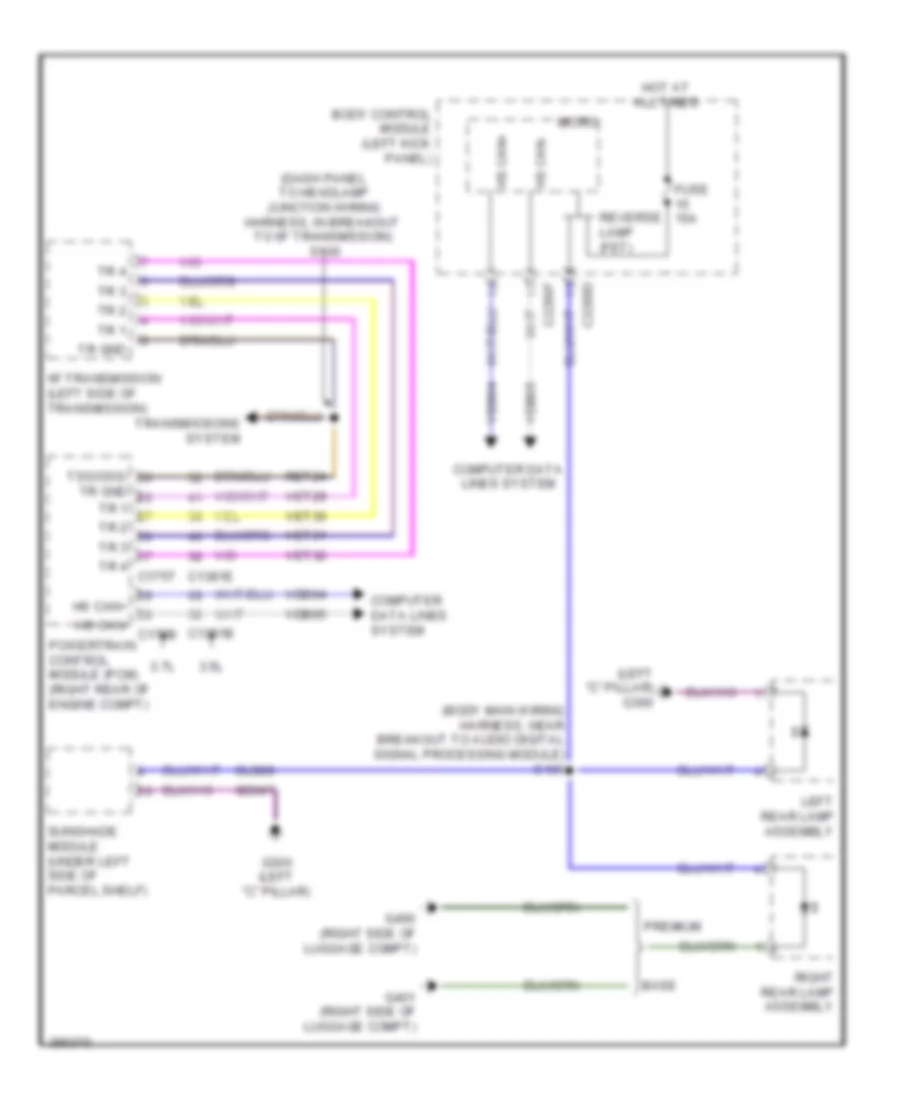
Backup Lamps Wiring Diagram for Lincoln MKS EcoBoost 2013
List of elements for Backup Lamps Wiring Diagram for Lincoln MKS EcoBoost 2013:
- (body main wiring harness, near breakout to audio digital signal processing module) s406
- (dash panel to headlamp junction wiring harness, in breakout to 6f transmission) s100
- (left "c" pillar) g300
- 3.5l
- 3.7l
- 6f transmission (left side of transmission)
- Base
- Body control module (left kick panel)
- C1381b
- C1381e
- C2280d
- C2280f
- Cls28
- Computer data lines system
- Fuse 15a
- G300 (left "c" pillar)
- G400 (right side of luggage compt)
- G401 (right side of luggage compt)
- Gd347
- Hot at all times
- Hs can+
- Hs can+ hs can- c175b
- Hs can-
- Left rear lamp assembly
- Micro
- Powertrain control module (pcm) (right rear of engine compt)
- Premium
- Ret24
- Reverse lamp (fet)
- Right rear lamp assembly
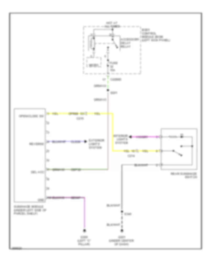
- Sunshade module (under left side of parcel shelf)
- Tr 1
- Tr 2
- Tr 3
- Tr 4
- Tr gnd
- Tr gnd tr 1 tr 2 tr 3 tr 4 c175t
- Transmissions system
- Tss/oss/
- Vdb04
- Vdb05
- Vet29
- Vet30
- Vet31
- Vet32
Exterior Lamps Wiring Diagram (1 of 2) for Lincoln MKS EcoBoost 2013
List of elements for Exterior Lamps Wiring Diagram (1 of 2) for Lincoln MKS EcoBoost 2013:
- (3.5l: dash panel to headlamp junction wiring harness, in breakout to c1100a) (3.7l: dash panel to headlamp junction wiring harness, in breakout to c211) s111
- (3.5l: dash panel to headlamp junction wiring harness, in breakout to c1100d) (3.7l: dash panel to headlamp wiring harness)
- (backup alarm jumper wiring harness, near breakout to outer left parking aid sensor) s421
- (body main wiring harness, near breakout to c3135) s328
- (body main wiring harness, near breakout to c316) s412
- (not used)
- 3.5l
- 3.7l
- Backup
- Backup lamps circuit
- Body control module (left kick panel)
- Bpp
- Bps
- C1381b
- C175b
- C210
- C2153c
- C2280b
- C2280c
- C2280d
- C2280f
- C405
- Ccb08
- Ces09
- Computer data lines system
- Fuse 15a
- Fuse 5a
- G100 (right side of engine compt)
- G300 (left "c" pillar)
- High mounted stoplamp capacitor (left "c" pillar)
- Hot at all times
- Hs can +
- Hs can -
- Left headlamp
- Left license plate lamp
- Left rear lamp assembly
- Lf turn lamp (fet)
- Lh led turn outage
- Lr turn lamp (fet)
- Micro
- Park
- Powertrain control module (pcm) (right rear of engine compt)
- Remote function actuator (rfa) module (right side of dash)
- Rf turn lamp (fet)
- Rh led turn outage
- Right headlamp
- Right license plate lamp
- Rr turn lamp (fet)
- S104
- S420
- Stop
- Stop/ chmsl (fet)
- Tail
- Turn
- Turn/ drl
- Vdb04
- Vdb05
Exterior Lamps Wiring Diagram (2 of 2) for Lincoln MKS EcoBoost 2013
List of elements for Exterior Lamps Wiring Diagram (2 of 2) for Lincoln MKS EcoBoost 2013:
- (under left side of dash) brake pedal position switch
- Auto
- Autolamp on
- Backup
- Backup lamps circuit
- Base
- Battery junction box (bjb) (left side of engine compt)
- Body control module (left kick panel)
- C2280a
- C2280b
- C2280d
- C2280e
- C2280f
- C2414a
- C475a
- C475b
- Cd374
- Clf19
- Clf23
- Clf24
- Cls32
- Cls34
- Computer data lines system
- Front control interface module (fcim) (center of dash)
- Fuse 10a
- Fuse 15a
- G102 (right rear of engine compt)
- G200 (under front of center console)
- G201 (under front of center of dash)
- G400 (right side of luggage compt)
- G401 (right side of luggage compt)
- G402 (right "c" pillar)
- Gd375
- Gnd
- Hazard
- Hazard switch
- Headlamp off
- Headlamp on
- Headlamp switch
- High mounted stoplamp
- Hot at all times
- Hs can +
- Hs can -
- Hs can+
- Hs can-
- I can +
- I can -
- Logic gnd
- Low
- Micro
- Multi- function switch
- Off
- Park
- Park lamp relay
- Park lamps on
- Premium
- Red
- Right rear lamp assembly
- S116 (3.7l)
- S239 red
- S246
- Sbp23
- Spb09
- Steering column control module (on steering column)
- Stop
- Tail
- Turn
- Vbatt
- Vdb04
- Vdb05
- Vdb13
- Vdb14
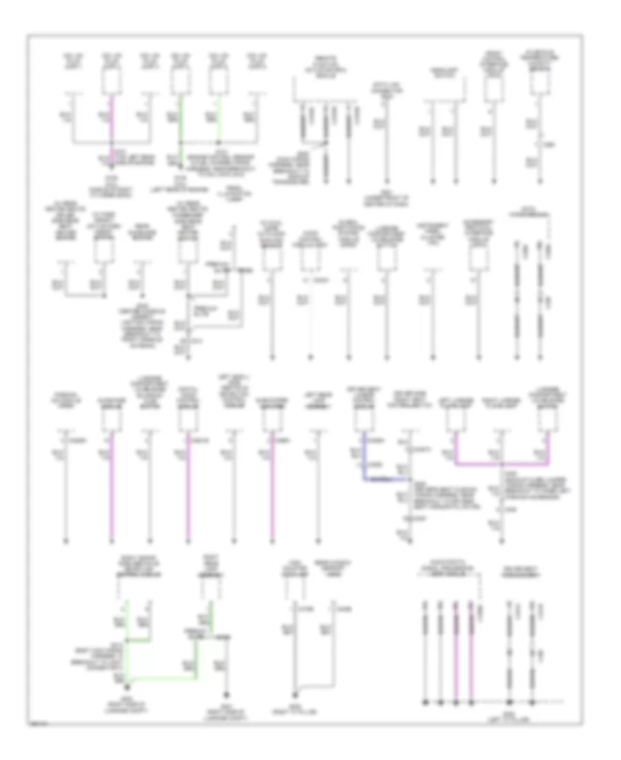
GROUND DISTRIBUTION
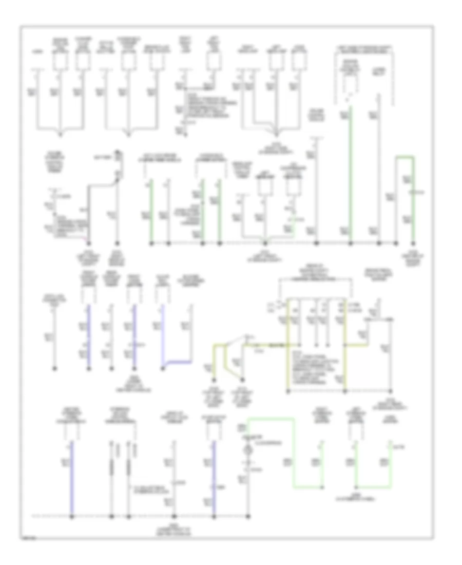
Ground Distribution Wiring Diagram (1 of 3) for Lincoln MKS EcoBoost 2013
List of elements for Ground Distribution Wiring Diagram (1 of 3) for Lincoln MKS EcoBoost 2013:
- (left side of engine compt) battery junction box
- (rear of engine compt)
- 3.5l
- 3.7l
- A/c compressor clutch field coil
- Active grille shutter
- Anti-lock brake system (abs) module
- Battery
- Blower motor speed control
- Brake fluid level switch
- Brake pedal
- Breakout to g104)
- C110
- C134
- C1381b
- C144
- C1467b
- C175b
- C214
- C217b
- C218a
- C218b
- C2414a
- C2414b
- C248
- C260
- Clockspring
- Control module (pscm)
- Cruise control module
- Data link connector (dlc)
- Engine cooling fan motor 2
- Engine cooling fan relay hfc 2
- Front cigar lighter
- Front console power point
- G100 (right side of engine compt)
- G101 (left front of engine compt)
- G102 (right rear of engine compt)
- G103 (left front of engine compt)
- G104 (right rear of engine)
- G105 (center of engine compt)
- G109 (top front of left cylinder bank)
- G110 (top front of left cylinder bank)
- G200 (under front of center console)
- Glove box lamp
- Head up display (hud) module
- Headlamp control module (hcm)
- Heated steering wheel module (hswm)
- Hood switch
- Horn
- Horn switch
- Left front fog lamp
- Left headlamp
- Left steering wheel switch
- Position (bpp) switch
- Power steering
- Powertrain control module (pcm)
- Rear console power point
- Right front fog lamp
- Right headlamp
- Right steering wheel switch
- S116 (3.5l: dash panel to headlamp junction wiring harness, in breakout to c1100d) (3.7l: dash panel to headlamp wiring harness)
- S183 (dash panel to headlamp wiring harness)
- S299 (in steering wheel)
- Start/stop switch
- Steering column control module (sccm)
- W/ adjustable steering column
- Washer fluid level switch
- Windshield washer pump motor
- Windshield wiper motor
- Wiper relay
Ground Distribution Wiring Diagram (2 of 3) for Lincoln MKS EcoBoost 2013
List of elements for Ground Distribution Wiring Diagram (2 of 3) for Lincoln MKS EcoBoost 2013:
- (w/ dual zone) autolamp/ sunload sensor
- (w/ park assist) active park assist switch
- (w/ rear heated seats)
- (w/ rear heated seats) driver side rear seat heater switch
- Accessory protocol interface module (apim)
- Audio control module (acm)
- Audio digital signal processing (dsp) module
- Base
- Breakout to inner left parking aid sensor)
- C2153c
- C2153d
- C2153e
- C228a
- C228c
- C238
- C240a
- C260
- C3050
- C3381
- C3385a
- C3387a
- C339
- C341a
- C341b
- C3521b
- C402b
- C405
- C4226a
- C4326c
- C466a
- C475b
- Coil on plug (cop) 1
- Coil on plug (cop) 2
- Coil on plug (cop) 3
- Coil on plug (cop) 4
- Coil on plug (cop) 5
- Coil on plug (cop) 6
- Data link connector (dlc)
- Datc hvac module
- Digital audio control module
- Driver seat lumbar control module
- Driver seat module (dsm)
- Driver side front seat control switch
- Front control interface module (fcim)
- G106 (3.5l) (middle of right cylinder bank)
- G108 (3.5l) (left rear of engine)
- G201 (under front of center of dash)
- G300 (left "c" pillar)
- G400 (right side of luggage compt)
- G401 (right side of luggage compt)
- G402 (right "c" pillar)
- Global positioning system module (gpsm)
- Headlamp switch
- High mounted stoplamp
- In-vehicle temperature/ humidity sensor
- Instrument panel cluster (ipc)
- Left (sod-l) side obstacle detection control module
- Left license plate lamp
- Left rear lamp assembly
- Luggage compartment lid release solenoid/ ajar switch
- Luggage compartment lid release switch
- Parking aid module (pam)
- Passenger side rear seat heater switch
- Premium/ elite
- Prndl illumination lamp
- Rear lamp assembly
- Rear sunshade switch
- Rear window defrost grid
- Remote function actuator (rfa) module
- Right
- Right (sod-r) side obstacle detection control module
- Right license plate lamp
- S141 (engine control sensor & fuel charge wiring harness, near breakout to coil on plug 5)
- S223 (main wiring harness, near breakout to backup transceiver)
- S340 (center console ambient lighting wiring harness, near breakout to front console antenna)
- S352 (driver's seat cushion wiring harness, near breakout to driver's seat horizontal motor)
- S413 (body main wiring harness, in breakout to joint connector 3)
- Side of engine)
- Subwoofer amplifier
- Sunshade module
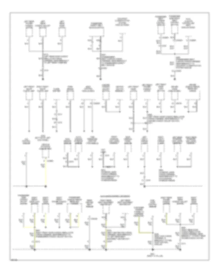
Ground Distribution Wiring Diagram (3 of 3) for Lincoln MKS EcoBoost 2013
List of elements for Ground Distribution Wiring Diagram (3 of 3) for Lincoln MKS EcoBoost 2013:
- (not
- (right "c" pillar)
- 4x4 control module
- Auto- dimming interior mirror
- Body control module (bcm)
- C214
- C215
- C219
- C2280d
- C3047
- C312
- C313
- C314
- C3265a m
- C3304b
- C3382
- C3386a
- C3388a
- C340
- C4396a
- C501b
- C919
- Customer access (taped to harness near c435)
- Driver door module (ddm)
- Driver side exterior rearview mirror
- Dual climate controlled seat module (dcsm)
- Floor shifter
- Front interior/ map lamps assembly
- Fuel pump control module
- G301
- G302 (bottom of left kick panel)
- Harness, near breakout to left rear seat backrest heater mat)
- Keypad switch assembly
- Left front door latch
- Left front door lock switch
- Left front power window motor
- Left front scuff plate lamp
- Left rear door latch
- Left rear interior/ map lamps assembly
- Left rear power window motor
- Left rear seat backrest heater mat
- Left rear window adjust switch
- Left vanity mirror lamp
- Master window adjust switch
- Nca
- Near breakout to occupant classification system module)
- Occupant classification system module (ocsm)
- Park brake switch
- Passenger safety belt buckle switch
- Passenger seat lumbar control module
- Passenger side exterior rearview mirror
- Passenger side front seat control switch
- Passenger side window adjust switch
- Rain sensor module
- Rear heated seat module
- Right front door latch
- Right front door lock switch
- Right front power window motor
- Right front scuff plate lamp
- Right rear door latch
- Right rear interior/ map lamps assembly
- Right rear power window motor
- Right rear seat backrest heater mat
- Right rear window adjust switch
- Right vanity mirror lamp
- Roof opening panel module
- S338 (body main wiring harness, in breakout to fuel pump control module)
- S351 (passenger's seat cushion wiring harness, near breakout to passenger's safety belt buckle)
- S712 (left rear door window regulator wiring harness, near breakout to left rear tweeter)
- S904 (interior lamps wiring harness, near breakout to auto-dimming interior mirror)
- S912 (interior lamps wiring harness, near breakout to auto-dimming interior mirror)
- Tire pressure monitor (tpm) module
- Used)
- Vehicle dynamics module (vdm)
- W/ climate controlled seats
- Wiring harness, near breakout to passenger's window adjust switch)
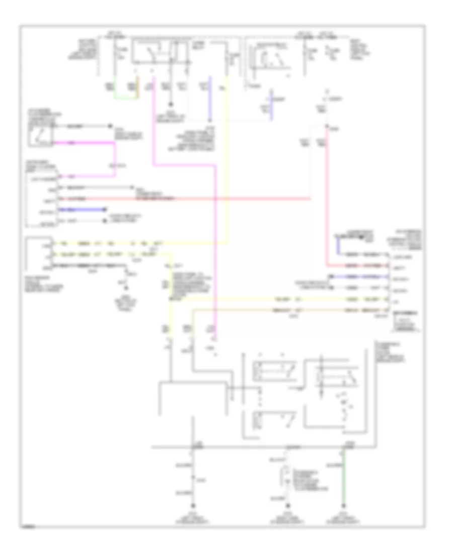
HEADLIGHTS
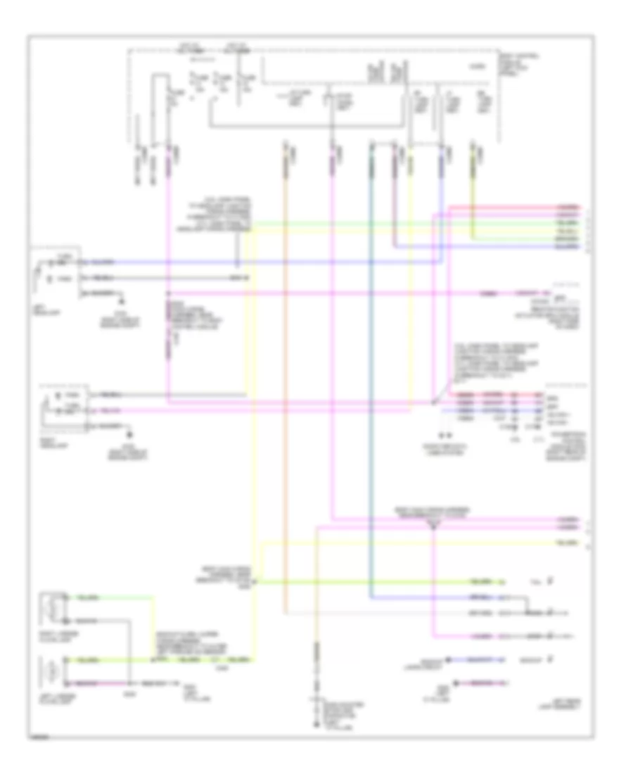
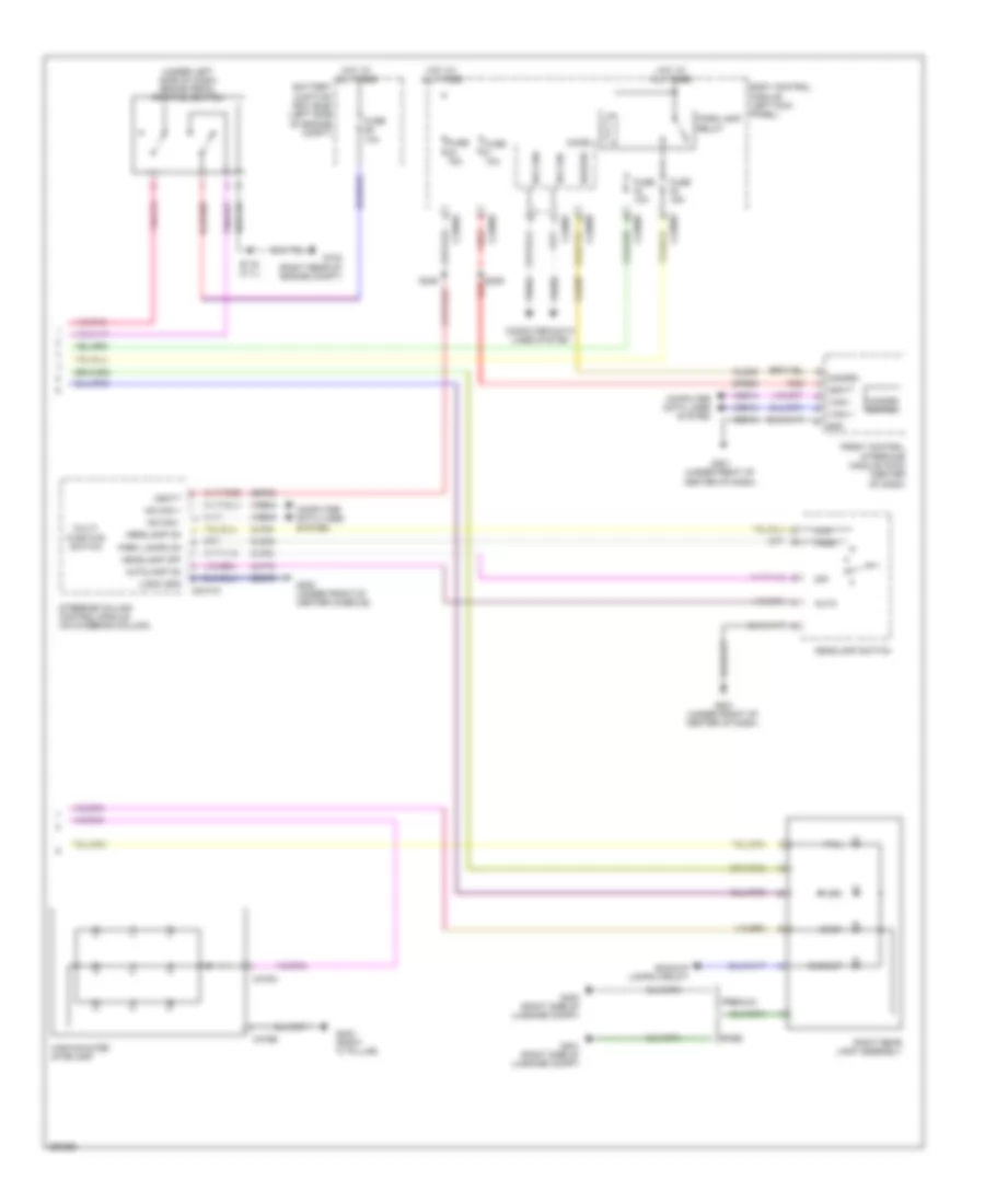
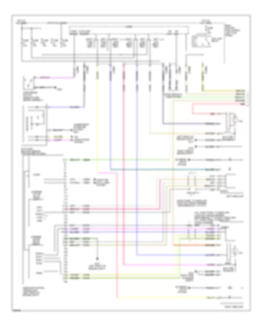
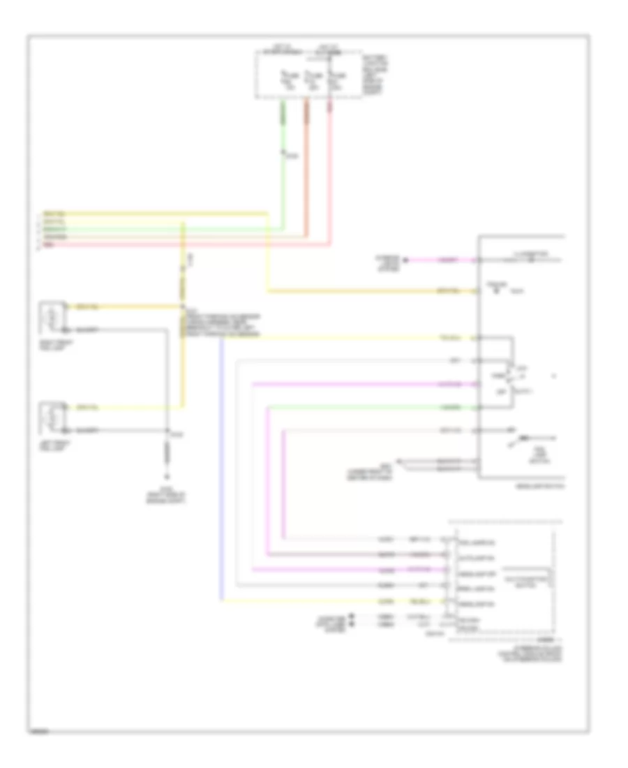
Headlights Wiring Diagram (1 of 2) for Lincoln MKS EcoBoost 2013
List of elements for Headlights Wiring Diagram (1 of 2) for Lincoln MKS EcoBoost 2013:
- (3.5l :dash panel to headlamp junction wiring harness, near breakout to right headlamp) (3.7l :dash panel to headlamp wiring harness) s105 s115
- (dash panel to headlamp junction wiring harness, near breakout to c110)
- (left front of engine compt) g101
- (under front of center of dash) g201
- Air conditioning system
- Autolamp sensor
- Autolamp/ sunload sensor (top center of dash)
- Body control module (bcm) (left kick panel)
- C2280a
- C2280b
- C2280c
- C2280e
- C2280f
- Cbb92
- Clf02
- Clf03
- Clf04
- Clf05
- Clf12
- Clf45
- Clf46
- Clf47
- Clf48
- Clf50
- Clf51
- Clf52
- Clf53
- Computer data lines system
- Dlf45
- Dlf50
- Exterior lights system
- Fog lamp relay
- Fuse 10a
- Fuse 15a
- G100 (right side of engine compt)
- G101 (left front of engine compt)
- G302
- Gd120
- Headlamp control module (hcm) (left front of engine compt)
- Hid
- Hot at all times
- Hs can+
- Hs can-
- Left headlamp
- Left high beam (fet)
- Left low beam (fet)
- Left turn lamp (fet)
- Lha1+
- Lha2-
- Lhb1+
- Lhb2-
- Micro
- Park brake
- Park brake switch (base of park brake assembly)
- Red
- Rha1+
- Rha2-
- Rhb1+
- Rhb2-
- Right headlamp
- Right high beam (fet)
- Right low beam (fet)
- Right turn lamp (fet)
- S114 s113
- Shield
- Shutter solenoid
- Solid state
- Stepper motor drive (left)
- Stepper motor drive (right)
- Vdb04
- Vdb05
- Vlf14
Headlights Wiring Diagram (2 of 2) for Lincoln MKS EcoBoost 2013
List of elements for Headlights Wiring Diagram (2 of 2) for Lincoln MKS EcoBoost 2013:
- Auto 1
- Autolamp on
- Battery junction box (bjb) (left side of engine compt)
- C110
- C2414a
- Clf19
- Clf21
- Clf23
- Clf24
- Cls34
- Computer data lines system
- Fog
- Fog ind
- Fog lamp switch
- Fog lamps on
- Fuse 10a
- Fuse 20a
- G100 (right side of engine compt)
- G201 (under front of center of dash)
- Headlamp off
- Headlamp on
- Headlamp switch
- Hot at all times
- Hot in start or run
- Hs can+
- Hs can-
- Illumination
- Interior lights system
- Left front fog lamp
- Low
- Micro
- Multi-function switch
- Off
- Park
- Park lamp on
- Red
- Right front fog lamp
- S130
- S131 (front parking aid sensor wiring harness, near breakout to outer left front parking aid sensor)
- S180
- Steering column control module (sccm) (on steering column)
- Vdb04
- Vdb05
HORN
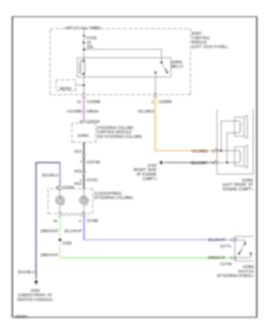
Horn Wiring Diagram for Lincoln MKS EcoBoost 2013
List of elements for Horn Wiring Diagram for Lincoln MKS EcoBoost 2013:
- Body control module (left kick panel)
- C217a
- C217b
- C218a
- C218b
- C218c nca
- C2280b
- C2280e
- C2414a
- C2414d
- Clockspring (steering column)
- Fuse 20a
- G100 (right side of engine compt)
- G200 (under front of center console)
- Horn
- Horn (left front of engine compt)
- Horn relay
- Horn switch (steering wheel)
- Hot at all times
- Micro
- Nca
- S299
- Steering column control module (on steering column)
INSTRUMENT CLUSTER
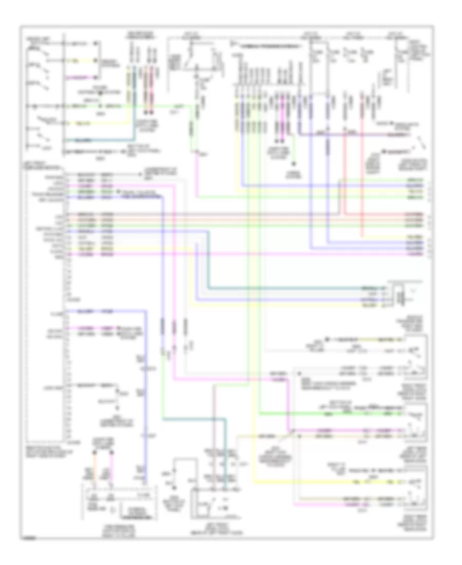
Instrument Cluster Wiring Diagram for Lincoln MKS EcoBoost 2013
List of elements for Instrument Cluster Wiring Diagram for Lincoln MKS EcoBoost 2013:
- (3.7l: lower left side of engine block)
- (rear of driver's door) left front door latch
- (under front of center of dash) g201
- 3.5l
- 3.7l
- Ajar fl
- Ajar fr
- Ajar lr
- Ajar rr
- Body control module (bcm) (left kick panel)
- Brake fluid level switch (on brake fluid reservoir)
- Brk fluid sw
- Brk fluid sw rtn
- C1381b
- C1381e
- C175b
- C175e
- C212
- C215
- C2280a
- C2280b
- C2280c
- C2280f
- C248
- C311
- C312
- C313
- C3135
- C314
- C3270
- Cbp35
- Cet52
- Cmc19
- Cmc20
- Cmc24
- Cmc25
- Computer data lines system
- Cpl26
- Cpl31
- Cpl36
- Cpl39
- Cpl58
- Eop sw
- Fuel level
- Fuel level 1 rtn
- Fuel level 2
- Fuel level sensor (fuel tank assembly)
- Fuel pump module (fuel tank)
- Fuel rtn
- Fuse 10a
- Fuse 15a
- Fuse 5a
- G100 (right side of engine compt)
- G200 (under front of center console)
- G300 (left "c" pillar)
- G301 (right "c" pillar)
- G302 (bottom of left kick panel)
- Gd374
- Gd375
- Gnd
- Head up display (hud) module (w/ adaptive cruise)
- Hot at all times
- Hot in start or run
- Hs can +
- Hs can -
- I can +
- I can -
- Instrument panel cluster (ipc)
- Isp-r
- Left rear door latch (rear of left rear door)
- Low washer
- Luggage compartment lid release solenoid/ajar switch (luggage compartment lid)
- Micro
- Oil pressure switch (3.5l: lower left rear of engine block)
- Park brake switch (base of park brake assembly)
- Park brk
- Park detect
- Pnk
- Powertrain control module (pcm) (right rear of engine compt)
- Right front door latch (rear of front passenger's door)
- Right rear door latch (rear of right rear door)
- Rmc19
- Rmc32
- Rmc33
- S236
- S237
- S246
- S500
- S600
- S712
- S800
- Sbp11
- Sbp23
- Shift interlock system
- Trunk ajar
- Vbatt
- Vdb04
- Vdb05
- Vdb13
- Vdb14
- Vmc11
- Vmc23
- Wiper/washer system
INTERIOR LIGHTS
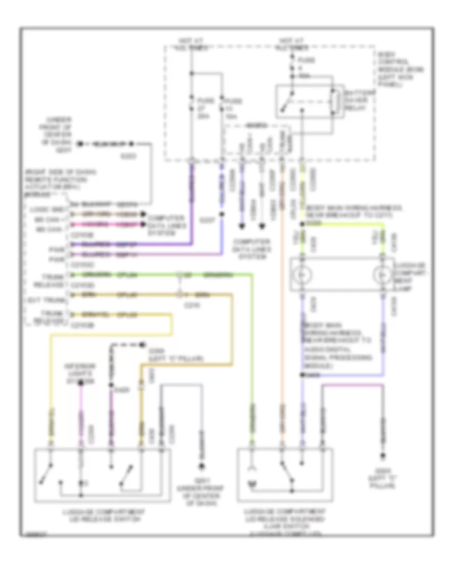
Courtesy Lamps Wiring Diagram (1 of 2) for Lincoln MKS EcoBoost 2013
List of elements for Courtesy Lamps Wiring Diagram (1 of 2) for Lincoln MKS EcoBoost 2013:
- (body main wiring harness, near breakout to audio digital signal processing module)
- (body main wiring harness, near breakout to c211) s220
- (bottom of left kick panel) g302
- (interior lamps wiring harness, near breakout
- (main wiring harness, near breakout to passenger's temperature blend door actuator)
- (rear of left front door) left front door latch
- Ajar fl
- Ajar fr
- Ajar lr
- Ajar rr
- Back- lighting led (fet)
- Battery saver relay
- Body control module (left kick panel)
- C215
- C219
- C2280a
- C2280b
- C2280c
- C2280d
- C311
- C312
- C313
- C314
- C4198
- C428
- Cpl26
- Cpl31
- Cpl36
- Cpl39
- Cpl58
- Driver side exterior rearview mirror
- Front interior/ map lamps assembly
- Fuse 10a
- Fuse 15a
- Fuse 2a
- G200 (under front of center console)
- G300 (left "c" pillar)
- G301 (right "c" pillar)
- G302 (bottom of left kick panel)
- Glove box lamp
- Hot at all times
- Interior lighting (fet)
- Left front scuff plate lamp
- Left rear door latch (rear of left rear door)
- Left rear interior/ map lamps assembly
- Left vanity mirror lamp
- Luggage compartment lamp
- Luggage compartment lid release solenoid/ ajar switch (luggage compt lid)
- Micro
- Module homelink
- Off
- Passenger side exterior rearview mirror
- Puddle lamp (fet)
- Right front door latch (rear of right front door)
- Right front scuff plate lamp
- Right rear door latch (rear of right rear door)
- Right rear interior/ map lamps assembly
- Right vanity mirror lamp
- S238
- S246
- S362 (body main wiring harness, near breakout to left front scuff plate lamp)
- S408
- S500
- S600
- S712
- S800
- S902
- S906 (in roof panel, front center)
- To auto-dimming interior mirror)
- Trunk ajar
Courtesy Lamps Wiring Diagram (2 of 2) for Lincoln MKS EcoBoost 2013
List of elements for Courtesy Lamps Wiring Diagram (2 of 2) for Lincoln MKS EcoBoost 2013:
- (main wiring harness, near breakout to glove box lamp)
- (main wiring harness, near breakout to rear sunshade switch)
- (under front of center console) g200
- C212
- C214
- C215
- C228a
- C228c
- C238
- C2414a
- C311
- C312
- Cln55
- Cln56
- Computer data lines system
- Dim
- Dim down
- Dim sw gnd
- Dim up
- Dome
- Dome defeat
- G201 (under front of center of dash)
- Gd374
- Gd375
- Gnd led rtn
- Green
- Hs can +
- Hs can -
- Hvac module (datc) (center of dash)
- Instrument panel dimmer switch
- Lamp dome
- Led gnd
- Left front footwell lamp
- Left front lamp assembly
- Logic gnd
- Micro
- Ms can +
- Ms can -
- Off
- Red
- Right front footwell lamp
- Right front lamp assembly
- Rln29
- Rln44
- S217
- S230
- S231
- S232
- S235
- S365 (console panel wiring harness, near breakout to top finish panel lamp)
- S366
- S367
- S369
- S370
- Sbp23
- Sbp46
- Steering column control module (on steering column)
- Storage bin lamp
- Top finish panel lamp
- Vbatt
- Vdb04
- Vdb05
- Vdb06
- Vdb07
- Vln36
- Vln48
- Vln49
- Vln50
- Vln58
- White
Instrument Illumination Wiring Diagram for Lincoln MKS EcoBoost 2013
List of elements for Instrument Illumination Wiring Diagram for Lincoln MKS EcoBoost 2013:
- (main wiring harness, near breakout to front cigar lighter) s373
- (main wiring harness, near breakout to passenger's temperature blend door actuator)
- (not used)
- (under front of center of dash) g201
- (w/ park assist) active park assist switch
- Auto 1
- Autolamp on
- Back- lighting led (fet)
- Base
- Body control module (bcm) (left kick panel)
- C214
- C215
- C2153d
- C218a
- C218b
- C2280a
- C2280b
- C2280d
- C2280f
- C2414a
- C260
- C311
- Clf19
- Clf23
- Clf24
- Cln55
- Cln56
- Clockspring (steering column)
- Cls34
- Computer data lines system
- Cpk28
- Dim down
- Dim sw gnd
- Dim up
- Dome
- Dome lp
- Driver side rear seat heated switch (if equipped)
- Fuse 15a
- Fuse 7.5a
- G200 (under front of center console)
- G201 (under front of center of dash)
- G302 (bottom of left kick panel)
- Gd375
- Gnd
- Headlamp off
- Headlamp switch
- Headlamps on
- Hot at all times
- Hs can +
- Hs can -
- Hs can+
- Hs can-
- Instrument panel dimmer switch
- Keypad illum
- Keypad switch assembly
- Left steering wheel switch
- Logic gnd
- Low
- Luggage compartment lid release switch
- Micro
- Off
- Park
- Park lamps on
- Passenger side rear seat heated switch (if equipped)
- Premium/elite
- Prndl illumination lamp
- Pwm input
- Rear sunshade switch
- Remote function actuator (rfa) module (right side of dash)
- Right steering wheel switch
- Rln29
- S215 (in steering wheel)
- S238
- S246
- S299
- S340 (premium/elite) (center console ambient lighting wiring harness, near breakout to front console antenna)
- S500
- S502
- Sbp23
- Start/stop switch
- Steering column control module (on steering column)
- Vbatt
- Vdb04
- Vdb05
- Vln36
- White led (fet)
MEMORY SYSTEMS
Driver"s Memory Seat Wiring Diagram, 12-Way Driver Seat (1 of 2) for Lincoln MKS EcoBoost 2013
List of elements for Driver"s Memory Seat Wiring Diagram, 12-Way Driver Seat (1 of 2) for Lincoln MKS EcoBoost 2013:
- (not used)
- Adj pedal fwd sw
- Aft
- Base backward
- Base forward
- Battery junction box (bjb) (left side of engine compt)
- Body control module (bcm) (left kick panel)
- C211
- C2280d
- C311
- C3381
- C339
- C341a
- C341b
- C341c
- C341d
- C501b
- Cbx03
- Cbx05
- Computer data lines system
- Cpm04
- Cpm16
- Cpm17
- Cpm20
- Cpm21
- Cpm22
- Cpm26
- Cpm28
- Cpm29
- Cpm31
- Cpm33
- Cpm34
- Cpm39
- Cpp09
- Cps01
- Cps02
- Cps03
- Cps04
- Cps05
- Cps06
- Cps07
- Cps08
- Cps14
- Cps15
- Cps16
- Cps23
- Cps24
- Cps25
- Cps26
- Cps27
- Cps28
- Cps29
- Cps30
- Driver door module (ddm)
- Driver seat module (dsm) (under driver's seat)
- Drv mirr horz pot
- Drv mirr horz sw
- Drv mirr mtr dn/lt
- Drv mirr mtr horz rt
- Drv mirr mtr vert up
- Drv mirr vert pot
- Drv mirr vert sw
- Forward
- Front down
- Front up
- Fuse 15a
- Fuse 30a
- Fuse 7.5a
- G300 (left "c" pillar)
- G302 (bottom of left kick panel)
- Gd133
- Gd905
- Gd906
- Gnd
- Hall effect return
- Hall effect sense
- Hot at all times
- Incline
- Left front door lock switch
- Logic
- Logic gnd
- Lpm30
- Memory mirrors circuit
- Memory set switch
- Mir fold sw
- Mirr com sw
- Mirr mtr fold in
- Mirr mtr fold out
- Mirr pot ret
- Ms can+
- Ms can-
- Pass mirr horz pot
- Pass mirr horz sw
- Pass mirr mtr dn/lt
- Pass mirr mtr horz rt
- Pass mirr mtr vert up
- Pass mirr pos feed
- Pass mirr vert pot
- Pass mirr vert sw
- Power distribution system
- Pwr gnd
- Rear down
- Rear up
- Recline
- Rpm11
- Rpm30
- Rps13
- S364
- S500
- S502
- Sbp07
- Set 1
- Set 2
- Set 3
- Vbatt
- Vdb06
- Vdb07
- Vpm35
- Vpm36
- Vpm37
- Vpm38
- Vps09
- Vps10
- Vps11
- Vps12
Driver"s Memory Seat Wiring Diagram, 12-Way Driver Seat (2 of 2) for Lincoln MKS EcoBoost 2013
List of elements for Driver"s Memory Seat Wiring Diagram, 12-Way Driver Seat (2 of 2) for Lincoln MKS EcoBoost 2013:
- (driver seat cushion wiring harness, near breakout to driver's seat horizontal motor) s368
- Aft
- C3050
- C3387a
- C3387b
- Deflate
- Down
- Driver seat front height motor (under driver's seat)
- Driver seat horizontal motor (under driver's seat)
- Driver seat lumbar height motor (driver's seat back)
- Driver seat lumbar motor (driver's seat back)
- Driver seat rear height motor (under driver's seat)
- Driver seat recliner motor (driver's seat back)
- Driver side front seat control switch
- Front height
- Fwd
- G300 (left "c" pillar)
- Horizontal
- Incline
- Inflate
- Lumbar
- Rear height
- Recline
- Red
- S352
Driver"s Memory Seat Wiring Diagram, 14-Way Driver Seat (1 of 2) for Lincoln MKS EcoBoost 2013
List of elements for Driver"s Memory Seat Wiring Diagram, 14-Way Driver Seat (1 of 2) for Lincoln MKS EcoBoost 2013:
- (not used)
- Adj pedal fwd sw
- Aft
- Base backward
- Base forward
- Battery junction box (bjb) (left side of engine compt)
- Body control module (bcm) (left kick panel)
- C211
- C2280b
- C2280d
- C311
- C3381
- C339
- C341a
- C341b
- C341c
- C341d
- C501b
- Cbx03
- Cbx05
- Computer data lines system
- Cpm04
- Cpm16
- Cpm17
- Cpm20
- Cpm21
- Cpm22
- Cpm26
- Cpm28
- Cpm29
- Cpm31
- Cpm33
- Cpm34
- Cpm39
- Cpp09
- Cps01
- Cps02
- Cps03
- Cps04
- Cps05
- Cps06
- Cps07
- Cps08
- Cps14
- Cps15
- Cps16
- Cps23
- Cps24
- Cps25
- Cps26
- Cps27
- Cps28
- Cps29
- Cps30
- Driver door module (ddm)
- Driver seat lumbar pump (driver's seat back)
- Driver seat module (dsm) (under driver's seat)
- Drv mirr horz pot
- Drv mirr horz sw
- Drv mirr mtr dn/lt
- Drv mirr mtr horz rt
- Drv mirr mtr vert up
- Drv mirr vert pot
- Drv mirr vert sw
- Ext mirr pot feed
- Forward
- Front down
- Front up
- Fuse 10a
- Fuse 15a
- Fuse 30a
- Fuse 7.5a
- G300 (left "c" pillar)
- G302 (bottom of left kick panel)
- Gd233
- Gd905
- Gd906
- Gnd
- Hall effect return
- Hall effect sense
- Hot at all times
- Hot in run or start
- Incline
- Left front door lock switch
- Logic gnd
- Lpm30
- Memory mirrors circuit
- Memory set switch
- Mirr com sw
- Mirr mtr fold in
- Mirr mtr fold out
- Mirr pot ret
- Mirror fold sw
- Ms can+
- Ms can-
- Pass mirr horz pot
- Pass mirr horz sw
- Pass mirr mtr dn/lt
- Pass mirr mtr horz rt
- Pass mirr mtr vert up
- Pass mirr vert pot
- Pass mirr vert sw
- Power distribution system
- Pwr gnd
- Rear down
- Rear up
- Recline
- Rpm11
- Rpm30
- Rps13
- S324
- S500
- S502
- Sbp07
- Set 1
- Set 2
- Set 3
- Vbatt
- Vdb06
- Vdb07
- Vpm35
- Vpm36
- Vpm37
- Vpm38
- Vps09
- Vps10
- Vps11
- Vps12
Driver"s Memory Seat Wiring Diagram, 14-Way Driver Seat (2 of 2) for Lincoln MKS EcoBoost 2013
List of elements for Driver"s Memory Seat Wiring Diagram, 14-Way Driver Seat (2 of 2) for Lincoln MKS EcoBoost 2013:
- (driver seat cushion wiring harness, near breakout to driver's seat horizontal motor) s368
- Aft
- C3050
- C3381
- C3385a
- C3385b
- C3387a
- C3387b
- Cps18
- Cps19
- Cps64
- Cps65
- Cpt05
- Cpt36
- Deflate
- Down
- Driver seat front height motor (under driver's seat)
- Driver seat horizontal motor (under driver's seat)
- Driver seat lumbar control module (in driver's seat back)
- Driver seat rear height motor (under driver's seat)
- Driver seat recliner motor (driver's seat back)
- Driver side front seat control switch
- Feed
- Fore
- Front height
- G300 (base of left "c" pillar)
- G300 (left "c" pillar)
- Gd904
- Gnd
- Horizontal
- Incline
- Inflate
- Lumbar
- Massage
- Motion
- Motion/ massage
- Motion/massage
- Rear height
- Recline
- Red
- Rpt05
- Rtn
- S352
- Sbx06
- Vbatt
Memory Mirrors Wiring Diagram for Lincoln MKS EcoBoost 2013
List of elements for Memory Mirrors Wiring Diagram for Lincoln MKS EcoBoost 2013:
- (left "c" pillar) g300
- (not used)
- Battery junction box (bjb) (left side of engine compt)
- Body control module (bcm) (left kick panel)
- C211
- C2280d
- C311
- C312
- C3381
- C339
- C341a
- C341b
- C341c
- C341d
- C501a
- C501b
- Cbx03
- Cbx05
- Computer data lines system
- Cpk19
- Cpk23
- Cpm03
- Cpm28
- Cpm29
- Cpm31
- Cpm33
- Cpm34
- Cps14
- Cps15
- Cps16
- Defogger system
- Door lock
- Door locks system
- Door unlock
- Driver door module (ddm)
- Driver seat module (dsm) (under driver's seat)
- Driver side exterior rearview mirror
- Drv mirr horz pot
- Drv mirr mtr dn/lt
- Drv mirr mtr horz rt
- Drv mirr mtr vert up
- Drv mirr vert pot
- Ec mirr +
- Ec mirr -
- Ext mirr pot feed
- Ext mirr pot rtn
- Fuse 30a
- Fuse 7.5a
- G301 (right "c" pillar)
- G302 (bottom of left kick panel)
- Gd233
- Gd905
- Gd906
- Gnd
- Hot at all times
- Interior lights system
- Left (sod-l) side obstacle detection control module (left side of luggage compt)
- Left exterior mirror blind spot (blis)/cross traffic alert (cta) led
- Left front door lock switch
- Logic gnd
- Lpm30
- Memory set switch
- Mirrors system
- Ms can+
- Ms can-
- Nca
- Pass mir dn/lt
- Pass mir horz pot
- Pass mir horz up
- Pass mir pos feed
- Pass mir pos rtn
- Pass mir ver up
- Pass mir vert pot
- Passenger side exterior rearview mirror
- Power distribution system
- Pwr gnd
- Right (sod-r) side obstacle detection control module (right side of luggage compt)
- Right exterior mirror blind spot (blis)/cross traffic alert (cta) led
- Rpm30
- S364
- S500
- S502
- S600
- Sbp07
- Set 1
- Set 2
- Set 3
- Vbatt
- Vdb06
- Vdb07
- Vpm35
- Vpm36
- Vpm37
- Vpm38
- W/ blind spot information system (blis)
Steering Column Memory Wiring Diagram for Lincoln MKS EcoBoost 2013
List of elements for Steering Column Memory Wiring Diagram for Lincoln MKS EcoBoost 2013:
- (main wiring harness, near breakout to joint connector 16) s212
- Adj pdl mtr (fwd)
- Adjustable pedal motor (under left side of dash)
- Adjustable pedal switch
- Body control module (left kick panel)
- C210
- C2280a
- C2414a
- C2414b
- C2414c
- C2414d
- C501b
- Com mtr pdl/col
- Computer data lines system
- Cpp01
- Cpp04
- Cpp05
- Cpp22
- Cps14
- Cps15
- Cps16
- Driver door module
- Fuse 15a
- G200 (under front of center console)
- G302 (bottom of left kick panel)
- Gd375
- Hot at all times
- Hs can +
- Hs can -
- Left front door lock switch
- Logic gnd
- Lpp06
- Memory set switch
- Ms can +
- Ms can -
- Pd/col hall sns rtn
- Pdl hall sns sig
- Pwr gnd
- Rpp06
- S243
- S244 (main wiring harness, near breakout to joint connector 16)
- S246
- S500
- Sbp23
- Sbp24
- Set 1
- Set 2
- Set 3
- Steering column control module (on steering column)
- Steering column telescoping motor (steering column)
- Steering column tilting motor (steering column)
- Tel mtr +/-
- Tel sns +
- Tilt mtr +/-
- Tilt sns +
- Vbatt
- Vdb04
- Vdb05
- Vdb06
- Vdb07
- Vpp08
- Vpp17
NAVIGATION
Blind Spot Information System Wiring Diagram for Lincoln MKS EcoBoost 2013
List of elements for Blind Spot Information System Wiring Diagram for Lincoln MKS EcoBoost 2013:
- Alert
- Body control module (bcm) (left kick panel)
- C2280d
- C311
- C312
- Cbp34
- Computer data lines system
- Crb02
- Crb04
- Driver side exterior rear view mirror
- Fuse 10a
- G300 (left "c" pillar)
- G302 (behind left kick panel)
- G400 (right side of luggage compt)
- Gd313
- Gd347
- Gnd
- Hot in run or start
- Hs can+
- Hs can-
- Instrument panel cluster (ipc)
- Left exterior mirror blind spot (blis)/ cross traffic alert (cta) led
- Left side obstacle detection control module (sod-l) (left side of luggage compt)
- Ms can+
- Ms can-
- Nca
- Passenger side exterior rear view mirror
- Right exterior mirror blind spot (blis)/ cross traffic alert (cta) led
- Right side obstacle detection control module (sod-r) (right side of luggage compt)
- Run/start
- S363
- S413
- S500
- S600
- Vdb06
- Vdb07
Navigation Wiring Diagram, with THX (1 of 3) for Lincoln MKS EcoBoost 2013
List of elements for Navigation Wiring Diagram, with THX (1 of 3) for Lincoln MKS EcoBoost 2013:
- Amp enable
- Audio digital signal processing (dsp) module (left side of luggage compt)
- Batt
- Body control module (bcm) (left kick panel)
- C215
- C2280a
- C2280d
- C313
- C314
- C4326a
- C4326b
- C4326c
- C712a
- C712b
- C813a
- C813b
- Center (hf) csa spkr+
- Center (hf) csa spkr-
- Computer data lines system
- Fuse 20a
- G201 (under front of center of dash)
- G300 (left "c" pillar)
- Gd347
- Gd374
- Global positioning system module (gpsm) (left side of dash)
- Gnd
- Gnd1
- Gnd2
- Gnd3
- Gnd4
- Hot at all times
- I can +
- I can -
- Left a-pillor spkr+
- Left a-pillor spkr-
- Left instrument panel speaker
- Left rear speaker
- Left rear tweeter
- Lf door spkr+
- Lf door spkr-
- Lf spkr+
- Lf spkr-
- Lh csa spkr+
- Lh csa spkr-
- Lh ip spkr+
- Lh ip spkr-
- Lr door spkr+
- Lr door spkr-
- Lr subw spkr+
- Lr subw spkr-
- Ms can +
- Ms can -
- Rear center spkr+
- Rear center spkr-
- Rear spkr+
- Rear spkr-
- Rf door spkr+
- Rf door spkr-
- Rf spkr+
- Rf spkr-
- Rh csa spkr+
- Rh csa spkr-
- Rh ip spkr+
- Rh ip spkr-
- Right a-pillor spkr+
- Right a-pillor spkr-
- Right instrument panel speaker
- Right rear speaker
- Right rear tweeter
- Rme01
- Rme02
- Rme06
- Rme07
- Rme08
- Rme09
- Rme10
- Rme11
- Rme12
- Rme17
- Rme18
- Rme28
- Rme29
- Rme30
- Rme80
- Rmea6
- Rr door spkr+
- Rr door spkr-
- Rr subw spkr+
- Rr subw spkr-
- S247
- S409
- S411
- Sbp05
- Sbp19
- Sbp29
- Sme23
- Sync alert+
- Sync alert-
- Vbat1
- Vbat2
- Vbat3
- Vbat4
- Vdb06
- Vdb07
- Vdb13
- Vdb14
- Vme01
- Vme02
- Vme06
- Vme07
- Vme08
- Vme09
- Vme10
- Vme11
- Vme12
- Vme17
- Vme18
- Vme28
- Vme29
- Vme30
- Vme80
- Vmea3
- Vmea4
- Vmea5
- Vmea7
- Vmea8
Navigation Wiring Diagram, with THX (2 of 3) for Lincoln MKS EcoBoost 2013
List of elements for Navigation Wiring Diagram, with THX (2 of 3) for Lincoln MKS EcoBoost 2013:
- (body main wiring harness, near breakout to audio digital signal processing module or c4208b) s405
- (body main wiring harness, near breakout to rear window defrost grid) s372
- (center of dash) accessory protocol interface module (apim)
- (center of dash) audio control module (acm)
- Am/fm ant
- Aux3 en
- Batt+
- C212
- C215
- C240a
- C311
- C312
- C316
- Ce336
- Central tweeter
- Coaxial cable
- Computer data lines system
- Dme17
- Dme80
- Electronic hidden antenna module (eham)
- G201 (under front of center of dash)
- Gd374
- I can+
- I can-
- Instrument panel speaker
- Left a-pillar speaker
- Left front speaker
- Left parcel shelf speaker
- Left sub
- Lf spkr+
- Lf spkr-
- Mid left
- Mid right
- Ms can +
- Nca
- Pwr gnd
- Rf spkr+
- Rf spkr-
- Right a-pillar speaker
- Right front speaker
- Right parcel shelf speaker
- Right sub
- Rme17
- Rme18
- Rme80
- S371
- S402
- S403
- S404
- Sbp29
- Sdars ant
- Shield
- Sme23
- Solid state
- Start
- Starting/ charging system
- Subwoofer
- Sw 12v
- Sync alert+
- Sync alert-
- Vdb13
- Vdb14
- Vme17
- Vme49
- Vme80
- W/ satellite radio
Navigation Wiring Diagram, with THX (3 of 3) for Lincoln MKS EcoBoost 2013
List of elements for Navigation Wiring Diagram, with THX (3 of 3) for Lincoln MKS EcoBoost 2013:
- (center of dash) front controls interface module (fcim)
- (steering column) clock spring
- (under front of center console) g200
- A/d 2
- A/d 4
- Batt
- Body control module (bcm) (left kick panel)
- C218b
- C218c
- C2280a
- C2280b
- C237
- C2414d
- C3521a
- C3521b
- Cls32
- Computer data lines system
- Digital audio control module (left side of luggage compt)
- Dmea3
- Front active noise control microphone (center front of roof)
- Fuse 10a
- Fuse 15a
- G201 (under front of center of dash)
- G300 (left "c" pillar)
- Gd347
- Gd374
- Gd375
- Gnd
- Hazard
- Hot at all times
- Hs can +
- Hs can -
- Hs can+
- Hs can- c2414a
- I can +
- I can -
- Interior lights system
- Left steering wheel switch
- Lf spkr+
- Lf spkr-
- Logic gnd
- Mic in+
- Mic in-
- Micro
- Mode
- Nca
- Pwr gnd
- Rear active noise control microphone (center rear of roof)
- Rear spkr+
- Rear spkr-
- Red
- Rf spkr+
- Rf spkr-
- Right steering wheel switch
- Rme57
- Rt sw gnd
- S239
- S246
- S295 (in steering wheel)
- S296
- Sbp05
- Sbp09
- Sbp23
- Seek+
- Seek-
- Sheld
- Steering column control module (sccm) (on steering column)
- Vbatt
- Vdb04
- Vdb05
- Vdb13
- Vdb14
- Vme57
- Vmea3
- Vmea4
- Vmea5
- Vmea6
- Vmea7
- Vmea8
- Vol+
- Vol-
Navigation Wiring Diagram, without THX (1 of 3) for Lincoln MKS EcoBoost 2013
List of elements for Navigation Wiring Diagram, without THX (1 of 3) for Lincoln MKS EcoBoost 2013:
- (center of dash) front controls interface module (fcim)
- Am/fm
- Amp anable
- Audio control module (acm) (center of dash)
- Aux in+
- Aux out+
- Aux out-
- Batt
- Batt+
- Body control module (bcm) (left kick panel)
- C212
- C215
- C2280a
- C2280b
- C2280d
- C240a
- C240b
- C466a
- C466b
- Ce336
- Center instrument panel speaker
- Clip detect
- Cls32
- Cntr spkr+
- Cntr spkr-
- Coaxial cable
- Computer data lines system
- Dme17
- Dme22
- Electronic hidden antenna module (eham)
- Fuse 10a
- Fuse 20a
- G201 (under front of center of dash)
- G201 (under right of center of dash)
- G300 (left "c" pillar)
- Gd374
- Global positioning system module (gpsm) (left side of dash)
- Gnd
- Hazard
- Hot at all times
- I can +
- I can -
- Lf spkr +
- Lf spkr -
- Lr spkr +
- Lr spkr -
- Lr subw spkr+
- Lr subw spkr-
- Micro
- Ml+
- Ml-
- Ms can +
- Ms can -
- Nca
- Pwr gnd
- Red
- Rf spkr +
- Rf spkr -
- Rme07
- Rme09
- Rme10
- Rme12
- Rme22
- Rme51
- Rme52
- Rme53
- Rme80
- Rr spkr +
- Rr spkr -
- Rr subw spkr+
- Rr subw spkr-
- S239
- S247
- Sbp09
- Sbp29
- Sdars
- Shield
- Sme23
- Sme56
- Solid state
- Start
- Starting/ charging system
- Stereo in l+
- Stereo in l-
- Stereo in r+
- Stereo in r-
- Subwoofer
- Subwoofer amplifier
- Sw 12v
- Sync radio circuit
- Vbatt
- Vdb06
- Vdb07
- Vdb13
- Vdb14
- Vme07
- Vme09
- Vme10
- Vme12
- Vme22
- Vme49
- Vme51
- Vme52
- Vme53
- Vme80
- W/ active noise control
- W/ satellite radio
- W/o active noise control
Navigation Wiring Diagram, without THX (2 of 3) for Lincoln MKS EcoBoost 2013
List of elements for Navigation Wiring Diagram, without THX (2 of 3) for Lincoln MKS EcoBoost 2013:
- (left side of luggage compt) digital audio control module
- Amp anable
- Batt
- C212
- C311
- C312
- C313
- C314
- C3521b
- C523a
- C523b
- C612a
- C612b
- C712a
- C712b
- C813a
- C813b
- G300 (left "c" pillar)
- Gd347
- Left a-pillar speaker
- Left front speaker
- Left rear speaker
- Left rear tweeter
- Lf spkr+
- Lf spkr-
- Lr spkr+
- Lr spkr-
- Nca
- Pwr gnd
- Rf spkr+
- Rf spkr-
- Right a-pillar speaker
- Right front speaker
- Right rear speaker
- Right rear tweeter
- Rme07
- Rme09
- Rme10
- Rme12
- Rr spkr+
- Rr spkr-
- Sbp05
- Sme56
- Vme07
- Vme09
- Vme10
- Vme12
- W/ active noise control
- W/o active noise control
Navigation Wiring Diagram, without THX (3 of 3) for Lincoln MKS EcoBoost 2013
List of elements for Navigation Wiring Diagram, without THX (3 of 3) for Lincoln MKS EcoBoost 2013:
- (steering column) clock spring
- (under front of center console) g200
- A/d 2
- A/d 4
- Body control module (bcm) (left kick panel)
- C218b
- C218c
- C2280a
- C2280d
- C237
- C2414d
- C3521a
- Computer data lines system
- Digital audio control module (left side of luggage compt)
- Front active noise control microphone (center front of roof)
- Fuse 15a
- Fuse 20a
- Gd375
- Hot at all times
- Hs can +
- Hs can -
- Hs can+
- Hs can- c2414a
- Interior lights system
- Left steering wheel switch
- Lf spkr+
- Lf spkr-
- Logic gnd
- Lr spkr-
- Mic in+
- Mic in-
- Mode
- Nca
- Rear active noise control microphone (center rear of roof)
- Rf spkr+
- Rf spkr-
- Right steering wheel switch
- Rme57
- Rr spkr+
- Rr spkr-
- Rt sw gnd
- S246
- S295 (in steering wheel)
- S296
- S409
- Sbp23
- Seek+
- Seek-
- Steering column control module (sccm) (on steering column)
- Vbatt
- Vdb04
- Vdb05
- Vme57
- Vol+
- Vol-
Parking Assistant Wiring Diagram for Lincoln MKS EcoBoost 2013
List of elements for Parking Assistant Wiring Diagram for Lincoln MKS EcoBoost 2013:
- (backup alarm jumper wiring harness, near breakout to inner right parking air sensor) s400
- (body main wiring harness, near breakout to c3135)
- (body main wiring harness, near breakout to c3135) (w/ active park assist) s329
- (front bumper)
- (front parking aid sensor wiring harness, near breakout to inner right front parking aid sensor)
- (front parking aid sensor wiring harness, near breakout to outer left front parking aid sensor)
- (rear of vehicle above left wheelwell) s327
- (w/ active park assist) s337
- (w/ front
- Active park assist switch (w/ active park assist)
- Batt pwr
- Body control module (bcm) (left kick panel)
- C110
- C211
- C212
- C214
- C215
- C2280d
- C405
- C4226a
- C4226b
- Cbp34
- Cmp09
- Cmp18
- Computer data lines system
- Front parking aid speaker (if equipped) (under right side of dash)
- Front sn gnd
- Front sn pwr
- Ft inner lh sn
- Ft inner rh sn
- Ft outer lh sn
- Ft outer rh sn
- Ft sounder -
- Fuse 10a
- G201 (under front of center of dash)
- G300 (left "c" pillar)
- Gd347
- Hot at all times
- Hs can +
- Hs can -
- Interior lights system
- Left active park assist sensor (w/ active park assist) (left corner of front bumper)
- Left front inner parking aid sensor
- Left front outer parking aid sensor
- Left rear inner parking aid sensor (rear bumper)
- Left rear outer parking aid sensor (rear bumper)
- Lf side sn
- Lmp06
- Lmp07
- Mirrors system
- Park assist sw
- Parking aid module (pam) (under left side of hatshelf)
- Parking aid speaker (under left side of hatshelf)
- Parking aid)
- Pwr gnd
- Rear sens gnd
- Rear sens pwr
- Rf side sn
- Right active park assist sensor (w/ active park assist) (right corner of front bumper)
- Right front inner parking aid sensor
- Right front outer parking aid sensor
- Right rear inner parking aid sensor (rear bumper)
- Right rear outer parking aid sensor (rear bumper)
- Ril sens
- Rir sens
- Rmp06
- Rmp07
- Rmp08
- Rmp09
- Rol sens
- Ror sens
- Rr sounder -
- S132
- S133
- S164
- S165
- S340
- S363
- S401 (backup alarm jumper wiring harness, near breakout to outer left parking aid sensor)
- Solid state
- Sounder +
- Vdb04
- Vdb05
- Vmp10
- Vmp11
- Vmp12
- Vmp13
- Vmp14
- Vmp15
- Vmp16
- Vmp17
- Vmp20
- Vmp21
Rear Camera Wiring Diagram for Lincoln MKS EcoBoost 2013
List of elements for Rear Camera Wiring Diagram for Lincoln MKS EcoBoost 2013:
- Accessory protocol interface module (apim) (center of dash)
- Auto-dimming interior mirror
- Batt
- Body control module (bcm) (left kick panel)
- C212
- C2280b
- C2280c
- C2280d
- Choke
- Computer data lines system
- Electronics
- Fuse 10a
- Hot at all times
- Hot in start or run
- Hs can+
- Hs can-
- Lin
- Micro
- Nca
- Rear camera video+
- Rear camera video-
- Red
- Rmp19
- S239
- S363
- Sbp09
- Un comm
- Vbatt
- Vdb04
- Vdb05
- Vdn03
- Video camera (center of luggage compt lid)
- Video+
- Video-
- Vmp19
POWER DISTRIBUTION
Power Distribution Wiring Diagram (1 of 5) for Lincoln MKS EcoBoost 2013
List of elements for Power Distribution Wiring Diagram (1 of 5) for Lincoln MKS EcoBoost 2013:
- (left side of engine compt) battery junction box (bjb)
- (not used)
- (seat heated pad wiring harness, in breakout c3047) s333
- Anti-lock brake system (abs) module
- Battery
- Battery junction box (bjb) (left side of engine compt)
- Blower motor relay
- Brake pedal position (bpp) switch
- C144
- C1467b
- C1617a
- C1617b
- C1617c
- C1617d
- C210
- C211
- C214
- C219
- C3047
- C3265a
- C3304b
- C3381
- C3382
- C341a
- Console power point
- Driver seat module (dsm)
- Dual climate controlled seat module (dcsm)
- Engine cooling fan relay hfc 1
- Engine cooling fan relay lfc
- Front cigar lighter
- Fuse 10a
- Fuse 15a
- Fuse 20a
- Fuse 30a
- Fuse 40a
- Fuse 50a
- Fuse link a (10 ga- red)
- Fuse link b (10 ga- red)
- G103 (left front of engine compt)
- G104 (right rear of engine)
- G200 (under front of center console)
- Generator
- High current battery junction box (bjb) (left side of engine compt)
- Left headlamp
- Mega fuse 1 100a
- Mega fuse 2 60a
- Mega fuse 4 100a
- Near breakout to occupant classification system module) s341
- Passenger side front seat control switch
- Power steering control module (pscm)
- Rear console power point
- Rear heated seat module
- Rear window defrost relay
- Red
- Right headlamp
- Roof opening panel module (if equipped)
- S127 (engine wiring harness, near breakout to starter motor)
- S128 (engine wiring harness, near breakout to starter motor)
- S129 (engine wiring harness, near breakout to red starter motor)
- Starter motor
- Starter relay
- To body control module (bcm) (diagram 3 of 5)
- To fuse 62 (diagram 2 of 5)
- Wiper relay
Power Distribution Wiring Diagram (2 of 5) for Lincoln MKS EcoBoost 2013
List of elements for Power Distribution Wiring Diagram (2 of 5) for Lincoln MKS EcoBoost 2013:
- (3.5l: engine control sensor & fuel charge wiring harness, near breakout to coil on plug 3) (3.7l: engine control sensor & fuel charge wiring harness, near breakout to electronic throttle control)
- (dash panel to headlamp junction wiring harness, near breakout to battery junction box)
- (dash panel to headlamp junction wiring harness, near breakout to battery junction box) s121
- (engine wiring harness, near breakout to starter motor) s168
- (left side of engine compt) battery junction box (bjb)
- (not used)
- 3.5l
- 3.7l
- A/c clutch relay
- Anti-lock brake system (abs) module
- Battery junction box (bjb) (left side of engine compt)
- Blower motor relay
- Body control module (bcm) (left kick panel)
- C134
- C1381b
- C144
- C1467a
- C175b
- C211
- C2280f
- C311
- C313
- C315
- Cruise control module (ccm)
- Evaporative emission (evap) canister vent valve
- Evaporative emission (evap) purge valve
- From fuse 59 b (diagram 1 of 5)
- From pcm power d relay (diagram 2 of 5)
- From splice s135 c (diagram 2 of 5)
- Fuel pump (fp) relay
- Fuse 10a
- Fuse 15a
- Fuse 20a
- Fuse 30a
- Fuse 5a
- Fuse 7.5a
- Headlamp control module (hcm)
- Heated oxygen sensor (ho2s) 12
- Heated oxygen sensor (ho2s) 12 (3.5l)
- Heated oxygen sensor (ho2s) 22
- Heated oxygen sensor (ho2s) 22 (3.5l)
- Left front power window motor
- Left rear power window motor
- Mass air flow/ intake air temperature (maf/iat) sensor
- Nca
- Pcm power relay
- Power steering control module (pscm)
- Powertrain control module (pcm)
- Rear window defrost relay
- Red
- Run/start (fet)
- Run/start relay
- S135
- S139
- S146
- S159 (3.5l: dash panel to headlamp junction wiring harness, in breakout to c1100d) (3.7l: dash panel to headlamp wiring harness)
- To body control module (bcm) (diagram 5 of 5)
- To fuse 67 (diagram 2 of 5)
- To fuse 68 (diagram 3 of 5)
- To splice s134 (diagram 2 of 5)
- Universal heated oxygen sensor (ho2s) 11
- Universal heated oxygen sensor (ho2s) 21
- Variable camshaft timing 11 (vct11) solenoid
- Variable camshaft timing 12 (vct12) solenoid (3.7l)
- Variable camshaft timing 21 (vct21) solenoid
- Variable camshaft timing 22 (vct22) solenoid (3.7l)
- Wiring harness, near breakout to battery junction box)
Power Distribution Wiring Diagram (3 of 5) for Lincoln MKS EcoBoost 2013
List of elements for Power Distribution Wiring Diagram (3 of 5) for Lincoln MKS EcoBoost 2013:
- (3.5l: engine control sensor & fuel charge wiring harness, near breakout to knock sensor) (3.7l: engine control sensor & fuel charge wiring harness, near breakout to electronic throttle control) s147
- (body main wiring harness, near breakout to g302) s364
- (dash panel to headlamp junction wiring harness, near breakout to battery junction box) s122
- (engine control sensor & fuel charge wiring harness, near breakout to coil on plug 3) s150
- (left front door window regulator wiring harness, near breakout to master window adjust switch) s502
- (left kick panel) body control module (bcm)
- (main wiring harness, near breakout to accessory protocol interface module) s242
- (main wiring harness, near breakout to passenger's temperature blend door actuator) s237
- (main wiring harness, near breakout to passenger's temperature blend door actuator) s239
- (main wiring harness, near breakout to steering column tilting motor) s246
- (main wiring harness, near breakout to steering column tilting motor) s247
- (not used)
- 3.5l
- 3.7l
- 4x4 control module
- A/c clutch relay
- Accessory protocol interface module (apim)
- Active grille shutter (ags) (3.7l)
- Audio control module (acm)
- Battery junction box (bjb) (left side of engine compt)
- Body control module (bcm) (left kick panel)
- C134
- C1381b
- C144
- C175b
- C210
- C211
- C2153c
- C2280a
- C2280b
- C2280d
- C2280g
- C237
- C2414a
- C248
- C260
- C311
- C312
- C314
- C339
- C341b
- C501b
- Coil on plug (cop) 1
- Coil on plug (cop) 2
- Coil on plug (cop) 3
- Coil on plug (cop) 4
- Coil on plug (cop) 5
- Coil on plug (cop) 6
- Driver door module (ddm)
- Driver seat module (dsm) (w/ memory)
- Engine cooling fan relay hfc 1
- Engine cooling fan relay hfc 2
- Engine cooling fan relay lfc
- Externally controlled variable displacement compressor (evdc)
- From e fuse 69 (diagram 2 of 5)
- From high current battery junction box (bjb) (diagram 1 of 5)
- Front controls interface module (fcim)
- Fuse 10a
- Fuse 15a
- Fuse 20a
- Fuse 30a
- Fuse 5a
- Fuse 7.5a
- G200 (under front of center console)
- Global positioning system module (gpsm)
- Head up display (hud) module
- Ignition transformer capacitor 1 (3.5l)
- Instrument panel cluster (ipc)
- Interior lights system
- Keypad switch assembly
- Liftgate release relay
- Micro
- Powertrain control module (pcm)
- Red
- Remote function actuator (rfa) module
- Right front power window motor
- Right rear power window motor
- Start/ stop 1
- Start/ stop 1 (active high)
- Start/ stop 2
- Start/ stop 2 (active low)
- Start/stop (led) (fet)
- Start/stop switch
- Steering column control module (sccm)
- Tire pressure monitor (tpm) module
- To fuse 5 (diagram 4 of 5)
- To keypad illu (fet) (diagram 5 of 5)
- Turbocharger (tc) wastegate regulating valve solenoid (3.5l)
- Turbocharger bypass (tcby) valve (3.5l)
- Turbocharger bypass (tcby2) valve (3.5l)
Power Distribution Wiring Diagram (4 of 5) for Lincoln MKS EcoBoost 2013
List of elements for Power Distribution Wiring Diagram (4 of 5) for Lincoln MKS EcoBoost 2013:
- (body main wiring harness, near breakout to audio digital signal processing module) s409
- (body main wiring harness, near breakout to c211) s220
- (interior lamps wiring harness, near breakout to auto-dimming interior mirror) s902
- (left front door window regulator wiring harness, near breakout to master window adjust switch) s504
- (left kick panel) body control module (bcm)
- (main wiring harness, near breakout to joint connector 16) (w/ adjustable steering column) s243
- (not used)
- (right front door window regulator wiring harness, near breakout to passenger's window adjust switch) s601
- Accessory delay relay
- Audio digital signal processing (dsp) module
- Battery saver relay
- C215
- C219
- C2280a
- C2280b
- C2280d
- C2280f
- C228a
- C238
- C2414b
- C311
- C312
- C313
- C314
- C339
- C3521b
- C4198
- C428
- C4326c
- Circuit breaker 30a
- Data link connector (dlc)
- Datc hvac module (automatic a/c)
- Digital audio control module
- Driver side front seat control switch
- From fuse 26 (diagram 3 of 5)
- Front interior/map lamps assembly
- Fuse 10a
- Fuse 15a
- Fuse 20a
- Glove box lamp
- Left front door lock switch
- Left front power window motor
- Left high beam (fet)
- Left rear interior/map lamps assembly
- Left rear power window motor
- Left vanity mirror lamp
- Luggage compartment lamp
- Master window adjust switch
- Micro
- Park lamp relay
- Passenger side window adjust switch
- Red
- Rev lp (fet)
- Right front door lock switch
- Right front power window motor
- Right high beam (fet)
- Right rear interior/map lamps assembly
- Right rear power window motor
- Right vanity mirror lamp
- Roof opening panel control switch
- Roof opening panel module
- Steering column control module (sccm) (w/ adjustable steering column)
- Stop/ chmsl (fet)
- Sunshade module
- To fuse 18 (diagram 5 of 5)
Power Distribution Wiring Diagram (5 of 5) for Lincoln MKS EcoBoost 2013
List of elements for Power Distribution Wiring Diagram (5 of 5) for Lincoln MKS EcoBoost 2013:
- (body main wiring harness, near breakout to audio digital signal processing module or c4208b) s411
- (body main wiring harness, near breakout to g302) s324
- (body main wiring harness, near breakout to g302) s363
- (dash panel to headlamp junction wiring harness, near breakout to battery junction box) s138
- (left kick panel) body control module (bcm)
- (main wiring harness, near breakout to passenger's temperature blend door actuator) (w/ head up display) s236
- (not used)
- 2nd row seat (fet)
- Audio digital signal processing (dsp) module
- Auto- dimming interior mirror
- Back- lighting led (fet)
- Battery junction box (bjb) (left side of engine compt)
- Bsi (fet)
- C211
- C215
- C219
- C2280b
- C2280d
- C2280e
- C2280f
- C2406
- C248
- C260
- C3047
- C3050
- C310a
- C3304b
- C3381
- C3382
- C3385a
- C3386a
- C340
- C4226a
- C4326c
- C4396b
- C466a
- C919
- Driver seat lumbar control module
- Fog lamp relay
- From battery junction box (bjb) (diagram 2 of 5)
- From fuse 39 j (diagram 4 of 5)
- From start/stop h (led) (fet) (diagram 3 of 5)
- Fuse 10a
- Fuse 15a
- Fuse 20a
- Fuse 5a
- Fuse 7.5a
- Head up display (hud) module (if equipped)
- Heated steering wheel module (hswm)
- Horn relay
- In-vehicle temperature/ humidity sensor
- Interior lighting (fet)
- Keypad illum (fet)
- Left corner lamp (fet)
- Left low beam (fet)
- Left side obstacle detection control module (sod-l) (if equipped)
- Lf turn lamp (fet)
- Lr stop/ turn lamp (fet)
- Lr turn lamp (fet)
- Micro
- Occupant classification system module (ocsm)
- Parking aid module (pam)
- Passenger seat lumbar control module
- Pcm wake up (fet)
- Premium audio
- Puddle lamp (fet)
- Rain sensor module
- Rear heated seat module
- Restraints control module (rcm)
- Rf turn lamp (fet)
- Right corner lamp (fet)
- Right low beam (fet)
- Right side obstacle detection control module (sod-r) (if equipped)
- Rr stop/ turn lamp (fet)
- Rr turn lamp (fet)
- Run/acc relay
- Subwoofer amplifier
- Thx audio
- Vehicle dynamics module (vdm)
- Video camera (w/ side obstacle detection)
- White light (fet)
- Wiper relay
POWER DOOR LOCKS
Power Door Locks Wiring Diagram (1 of 2) for Lincoln MKS EcoBoost 2013
List of elements for Power Door Locks Wiring Diagram (1 of 2) for Lincoln MKS EcoBoost 2013:
- (bottom of left kick panel) g302
- (right "c" pillar)
- (right "c" pillar) g301
- (under front of center of dash) g201
- Acce- ssory delay relay
- Ajar
- Backup transceiver (right end of dash)
- Body control module (left kick panel)
- C212
- C215
- C2153d
- C2153e
- C2280a
- C2280b
- C2280c
- C2280d
- C2280e
- C2280f
- C237
- C311
- C312
- C313
- C314
- C501a
- C501b
- Clf02
- Clock
- Computer data lines system
- Cpk19
- Cpk23
- Cpk28
- Cpl11
- Cpl25
- Cpl26
- Cpl31
- Cpl36
- Cpl39
- Cpl51
- Cpl52
- Cpl84
- Crh04
- Data
- Dr lock
- Dr unlock
- Driver door module (ddm)
- Drv unlock
- Fl ajar
- Fr ajar
- Fuse 10a
- Fuse 15a
- Fuse 20a
- Fuse 5a
- Fuse 7.5a
- G100 (right side of engine compt)
- G201 (under front of center of dash)
- G301
- G302 (bottom of left kick panel)
- Gd374
- Gnd
- Headlights system
- Hood ajar
- Hood switch (left front of engine compt)
- Horn relay
- Horns system
- Hot at all times
- Internal antenna rke receiver
- Internal tpms/rke antenna
- K-line
- Keypad illum
- Left front door latch (rear of left front door)
- Left front door lock switch
- Left hi beam (fet)
- Left rear door latch (rear of left rear door)
- Lock
- Logic gnd
- Lpk32
- Lr ajar
- Memory set switch
- Memory systems
- Micro
- Ms can +
- Ms can -
- Ms can+
- Ms can-
- Pass lock
- Pass unlock
- Pats gnd
- Pats vcc
- Power distribution system
- Pwr gnd
- Remote function actuator (rfa) module (right side of dash)
- Right front door latch (rear of right front door)
- Right rear door latch (rear of right rear door)
- Rpk32
- Rpk39
- Rr ajar
- S201
- S223
- S237
- S306 (body main wiring harness, near breakout to c313)
- S321 (body main wiring harness, near breakout to c3375)
- S364
- S500
- S504
- S600
- S800
- Set 1
- Set 2
- Set 3
- State solid
- Tire pressure monitor module (right "c" pillar)
- Tpms receiver
- Trunk release
- Trunk, tailgate, fuel doors system
- Unlock
- Vcc
- Vdb06
- Vdb07
- Vpk32
- Vpk33
- Vpk39
- Vpk40
- Vpl56
Power Door Locks Wiring Diagram (2 of 2) for Lincoln MKS EcoBoost 2013
List of elements for Power Door Locks Wiring Diagram (2 of 2) for Lincoln MKS EcoBoost 2013:
- (behind center of rear bumper) luggage compartment intelligent access (ia) antenna
- 1/2
- 3/4
- 5/6
- 7/8
- 9/0
- Bpp
- C212
- C214
- C215
- C2153a
- C2153b
- C2153c
- C260
- C311
- C312
- C405
- Ccb08
- Cdc35
- Console front antenna (under front end of center console)
- Console rear antenna (under rear end of center console)
- Cpk29
- Cpk30
- Cpk31
- Cpl45
- Cpl60
- Ext trunk
- Exterior lights system
- Fla
- Fla rtn
- Fra
- Fra rtn
- G201 (under front of center of dash)
- G301 (right "c" pillar)
- G302 (bottom of left kick panel)
- Gd374
- Ia1
- Ia1 rtn
- Ia2
- Ia2 rtn
- Ia3
- Ia3 rtn
- Keyless entry keypad
- Keypad a
- Keypad b
- Keypad c
- Left front exterior door handle
- Lock
- Logic
- Micro
- Power distribution system
- Pwr
- Pwr gnd
- Remote function actuator (rfa) module (right side of dash)
- Right front door lock switch
- Right front exterior door handle
- Rpk01
- Rpk02
- Rpk05
- Rpk06
- Rpk07
- Rpk08
- S223
- S229 (main wiring harness, near breakout to remote function actuator)
- S242
- S500
- S502
- S600
- S601
- Sbp11
- Sbp27
- Seat antenna
- Solid state
- Start/stop 1
- Start/stop switch
- Trunk
- Trunk release
- Trunk rtn
- Trunk, tailgate, fuel doors system
- Unlock
- Vpk01
- Vpk02
- Vpk05
- Vpk06
- Vpk07
- Vpk08
POWER MIRRORS
Power Mirrors Wiring Diagram for Lincoln MKS EcoBoost 2013
List of elements for Power Mirrors Wiring Diagram for Lincoln MKS EcoBoost 2013:
- Active park assist switch
- Auto-dimming interior mirror
- Body control module (bcm) (left kick panel)
- C214
- C215
- C219
- C2280d
- C237
- C311
- C9048a
- C9048b
- C919
- Camera windshield defrost heater (top center of windshield)
- Cbp34
- Cmc47
- Computer data lines system
- Crb08
- Driver side exterior rearview mirror
- Ec mirr +
- Ec mirr -
- Front video camera
- Fuse 10a
- G302 (bottom of left kick panel)
- Gd233
- Gnd
- Hot in run or start
- Hs can +
- Hs can -
- Htr +
- Htr -
- Lane departure
- Lrd12
- Mirr +
- Mirr-
- Rrb08
- Rrd12
- S363
- S912
- Vdb04
- Vdb05
- Vpwr
POWER SEATS
Adjustable Pedal Wiring Diagram for Lincoln MKS EcoBoost 2013
List of elements for Adjustable Pedal Wiring Diagram for Lincoln MKS EcoBoost 2013:
- (main wiring harness, near breakout to joint connector 16)
- (under front of center console) g200
- Adj pdl mtr (fwd)
- Adjustable pedal motor (under left side of dash)
- Adjustable pedal switch
- Body control module (left kick panel)
- C210
- C2280a
- C2414a
- C2414b
- Com mtr pdl/col
- Computer data lines system
- Cpp01
- Cpp05
- Fuse 15a
- Gd375
- Hot at all times
- Hs can +
- Hs can -
- Lpp06
- Memory systems
- Pd/col hall sns rtn
- Pdl hall sns sig
- Pwr gnd
- Rpp06
- S212
- S244
- S246
- Sbp23
- Steering column control module (on steering column)
- Vbatt
- Vdb04
- Vdb05
Climate Control Seats Wiring Diagram for Lincoln MKS EcoBoost 2013
List of elements for Climate Control Seats Wiring Diagram for Lincoln MKS EcoBoost 2013:
- Battery junction box (bjb) (left side of engine compt)
- C211
- C228a
- C3050
- C3265a
- C3265b
- C3265c
- C3381
- C3382
- C340
- Cbx01
- Chs01
- Chs02
- Chs03
- Chs06
- Chs07
- Chs08
- Chs09
- Chs14
- Chs29
- Computer data lines system
- Dbckblwctl
- Dbksensrt
- Dbkted+
- Dbkted-
- Dblwr+
- Dblwr-
- Dcshcblwctl
- Dcshsens
- Dcshsensrt
- Dcshted+
- Dcshted-
- Driver side seat backrest thermo-electric device (driver's seat back)
- Driver side seat cushion thermo-electric device (driver's seat cushion)
- Drv batt
- Dual climate controlled seat module (under front passenger's seat)
- Fuse 30a
- G302 (bottom of left kick panel)
- Gd903
- Gnd
- Hot at all times
- Hvac module (datc) (center of dash)
- Ms can+
- Ms can-
- Nca
- Pass batt
- Passenger side seat backrest thermo-electric device (front passenger's seat back)
- Passenger side seat cushion thermo-electric device (front passenger's seat cushion)
- Pbckblwctl
- Pbksens
- Pbksensrt
- Pbkted+
- Pbkted-
- Pblwr+
- Pblwr-
- Pcshcblwctl
- Pcshsens
- Pcshsensrt
- Pcshted+
- Pcshted-
- Rhs01
- Rhs02
- Rhs03
- Rhs05
- Rhs06
- Rhs07
- Rhs08
- Rhs10
- Rhs20
- S301
- S302 (passenger's seat cushion wiring harness, near breakout to dual climate controlled seat module)
- S303
- S341
- S350
- Thermal electric device
- Vdb06
- Vdb07
- Vhs18
- Vhs21
- Vhs23
- Vhs26
- Vhs27
- Vhs36
Passenger Power Seat Wiring Diagram, 12-Way for Lincoln MKS EcoBoost 2013
List of elements for Passenger Power Seat Wiring Diagram, 12-Way for Lincoln MKS EcoBoost 2013:
- (not used)
- Aft
- Battery junction box (bjb) (left side of engine compt)
- C211
- C3382
- C3388a
- C3388b
- C340
- Deflate
- Down
- Front height
- Fuse 30a
- Fwd
- G302 (bottom of left kick panel)
- Horizontal
- Hot at all times
- Incline
- Inflate
- Lumbar
- Passenger seat front height motor (under front passenger's seat)
- Passenger seat horizontal motor (under front passenger's seat)
- Passenger seat lumbar height motor (passenger's seat back)
- Passenger seat lumbar motor (passenger's seat back)
- Passenger seat rear height motor (under front passenger's seat)
- Passenger seat recliner motor (passenger's seat back)
- Passenger side front seat control switch
- Rear height
- Recline
- Red
- S350
Passenger Power Seat Wiring Diagram, 14-Way (1 of 2) for Lincoln MKS EcoBoost 2013
List of elements for Passenger Power Seat Wiring Diagram, 14-Way (1 of 2) for Lincoln MKS EcoBoost 2013:
- (not used)
- Aft
- Battery junction box (bjb) (left side of engine compt)
- C211
- C3382
- C3388a
- C3388b
- C340
- Deflate
- Down
- Fore
- Front height
- Fuse 30a
- G302 (bottom of left kick panel)
- Horizontal
- Hot at all times
- Incline
- Inflate
- Lumbar
- Massage
- Motion
- Motion/mass
- Passenger seat front height motor (under front passenger's seat)
- Passenger seat horizontal motor (under front passenger's seat)
- Passenger seat rear height motor (under front passenger's seat)
- Passenger seat recliner motor (passenger's seat back)
- Passenger side front seat control switch
- Rear height
- Recline
- Red
- S350
Passenger Power Seat Wiring Diagram, 14-Way (2 of 2) for Lincoln MKS EcoBoost 2013
List of elements for Passenger Power Seat Wiring Diagram, 14-Way (2 of 2) for Lincoln MKS EcoBoost 2013:
- (bottom of left kick panel) g302
- Body control module (bcm) (left kick panel)
- C2280b
- C3382
- C3386a
- C3386b
- C340
- Cps18
- Cps19
- Cps64
- Cps65
- Cpt05
- Cpt36
- Deflate
- Down
- Feed
- Fuse 10a
- Gd904
- Gnd
- Hot in run or start
- Inflate
- Motion/massage
- Passenger seat lumbar control module (front passenger's seat back)
- Passenger seat lumbar pump (front passenger's seat back)
- Rpt05
- Rtn
- S324
- S350
- Sbx06
- Vbatt
Rear Heated Seats Wiring Diagram for Lincoln MKS EcoBoost 2013
List of elements for Rear Heated Seats Wiring Diagram for Lincoln MKS EcoBoost 2013:
- (under left side of rear seat) s334
- Backlighting ind
- Battery junction box (bjb) (left side of engine compt)
- Body control module (bcm) (left kick panel)
- C211
- C212
- C214
- C2280d
- C3047
- C3304a
- C3304b
- Cbp34
- Chs46
- Chs47
- Chs48
- Chs49
- Chs50
- Chs51
- Chs52
- Chs53
- Chs54
- Chs58
- Driver side rear seat heated switch
- Drv batt
- Fuse 10a
- Fuse 20a
- G201 (under front of center of dash)
- G301 (right "c" pillar)
- Gd348
- Gnd
- High ind
- Hot at all times
- Hot in start or run
- Interior lights system
- Left rear seat
- Left rear seat backrest heater mat
- Low ind
- Lr heater fd
- Lr high led
- Lr high/off
- Lr low led
- Lr low/off
- Lr seat ntc
- Nca
- Off/ high
- Off/ low
- Pass batt
- Passenger side rear seat heated switch
- Rear heated seat module (under left rear seat)
- Rear seat cushion heater mat
- Return
- Rhs41
- Right rear seat
- Right rear seat backrest heater mat
- Rr heater fd
- Rr high led
- Rr high/off
- Rr low led
- Rr low/off
- Rr seat ntc
- Run/start
- S332
- S333
- S340
- S363
- Sbb21
- Vhs42
- Vhs45
POWER TOP/SUNROOF
Power Top/Sunroof Wiring Diagram for Lincoln MKS EcoBoost 2013
List of elements for Power Top/Sunroof Wiring Diagram for Lincoln MKS EcoBoost 2013:
- Accessory delay relay
- Battery junction box (bjb) (left side of engine compt)
- Body control module (bcm) (left kick panel)
- C211
- C215
- C219
- C2280b
- C2280c
- Cbp38
- Cdc41
- Close
- Common glass
- Cpr31
- Cpr38
- Cpr39
- Cpr40
- Cpr86
- Cpr87
- Cpw01
- Del acc
- Fuse 10a
- Fuse 30a
- G302 (bottom of left kick panel)
- Gd233
- Global
- Gnd
- Hot at all times
- Micro
- Open
- Park
- Power windows system
- Pulse train (fet)
- Roof opening panel control switch
- Roof opening panel module (center front of roof)
- S311 (body main wiring harness, near breakout to g302)
- S903
- S904
- Sbb08
- Shift interlock system
- Slide switch
- Ss close
- Ss open
- Tilt
POWER WINDOWS
Power Windows Wiring Diagram (1 of 2) for Lincoln MKS EcoBoost 2013
List of elements for Power Windows Wiring Diagram (1 of 2) for Lincoln MKS EcoBoost 2013:
- Accessory delay relay
- Auto
- Body control module (bcm) (left kick panel)
- C1617b
- C2280c
- C2280d
- C2280g
- C311
- C312
- C313
- Del acc
- Down
- Fuse 15a
- G301 (right "c" pillar)
- G302 (bottom of left kick panel)
- Gnd
- High current battery junction box (bjb) (left side of engine compt)
- Hot at all times
- Left front
- Left front power window motor (driver's door)
- Left rear
- Lock out
- Master window adjust switch
- Mega fuse 1 100a
- Micro
- Mirror switches
- Mirrors system
- Passenger side window adjust switch
- Power distribution system
- Pulse train
- Pulse train (fet)
- Pwr
- Red
- Right front
- S201
- S311 (body main wiring harness, near breakout to g302)
- S500
- S504
- S600
- S602 (right front door window regulator wiring harness, near breakout to passenger's window adjust switch)
- S603
- Vbatt
Power Windows Wiring Diagram (2 of 2) for Lincoln MKS EcoBoost 2013
List of elements for Power Windows Wiring Diagram (2 of 2) for Lincoln MKS EcoBoost 2013:
- (body main wiring harness, near breakout to c313) s313
- (left rear door window regulator wiring harness, near breakout to left rear power window motor)
- (left rear door window regulator wiring harness, near breakout to left rear tweeter)
- (left rear door)
- (right rear door window regulator wiring harness, near breakout to right rear power window motor)
- (right rear door window regulator wiring harness, near breakout to right rear tweeter) s802
- Auto
- Battery junction box (bjb) (left side of engine compt)
- Body control module (bcm) (left kick panel)
- C211
- C2280d
- C311
- C312
- C313
- C314
- Del acc
- Down
- Fuse 30a
- G301 (right "c" pillar)
- G302 (bottom of left kick
- G302 (bottom of left kick panel)
- Gnd
- Hot at all times
- Left rear power window motor
- Left rear window adjust switch
- Panel)
- Pulse train
- Red
- Right front power window motor (front passenger's door)
- Right rear power window motor (right rear door)
- Right rear window adjust switch
- S600
- S601
- S701
- S702
- S712
- S800
- S801
- System distribution power
- Vbatt
Rear Window Sun Shade Wiring Diagram for Lincoln MKS EcoBoost 2013
List of elements for Rear Window Sun Shade Wiring Diagram for Lincoln MKS EcoBoost 2013:
- Accessory delay relay
- Body control module (bcm) (left kick panel)
- C214
- C215
- C2280d
- Cbp32
- Cls28
- Cpr88
- Del acc
- Exterior lights system
- Fuse 15a
- G201 (under center of dash)
- G300 (left "c" pillar)
- Gd347
- Gnd
- Hot at all times
- Interior lights system
- Micro
- Open/close sw
- Rear sunshade switch
- Reverse
- S201
- S340
- Sunshade module (under left side of parcel shelf)
RADIO
Radio Wiring Diagram, with THX (1 of 3) for Lincoln MKS EcoBoost 2013
List of elements for Radio Wiring Diagram, with THX (1 of 3) for Lincoln MKS EcoBoost 2013:
- Amp enable
- Audio digital signal processing (dsp) module (left side of luggage compt)
- Batt
- Body control module (bcm) (left kick panel)
- C215
- C2280a
- C2280d
- C313
- C314
- C4326a
- C4326b
- C4326c
- C712a
- C712b
- C813a
- C813b
- Center (hf) csa spkr+
- Center (hf) csa spkr-
- Computer data lines system
- Fuse 20a
- G201 (under front of center of dash)
- G300 (left "c" pillar)
- Gd347
- Gd374
- Global positioning system module (gpsm) (left side of dash)
- Gnd
- Gnd1
- Gnd2
- Gnd3
- Gnd4
- Hot at all times
- I can +
- I can -
- Left a-pillor spkr+
- Left a-pillor spkr-
- Left instrument panel speaker
- Left rear speaker
- Left rear tweeter
- Lf door spkr+
- Lf door spkr-
- Lf spkr+
- Lf spkr-
- Lh csa spkr+
- Lh csa spkr-
- Lh ip spkr+
- Lh ip spkr-
- Lr door spkr+
- Lr door spkr-
- Lr subw spkr+
- Lr subw spkr-
- Ms can +
- Ms can -
- Rear center spkr+
- Rear center spkr-
- Rear spkr+
- Rear spkr-
- Rf door spkr+
- Rf door spkr-
- Rf spkr+
- Rf spkr-
- Rh csa spkr+
- Rh csa spkr-
- Rh ip spkr+
- Rh ip spkr-
- Right a-pillor spkr+
- Right a-pillor spkr-
- Right instrument panel speaker
- Right rear speaker
- Right rear tweeter
- Rme01
- Rme02
- Rme06
- Rme07
- Rme08
- Rme09
- Rme10
- Rme11
- Rme12
- Rme17
- Rme18
- Rme28
- Rme29
- Rme30
- Rme80
- Rmea6
- Rr door spkr+
- Rr door spkr-
- Rr subw spkr+
- Rr subw spkr-
- S247
- S409
- S411
- Sbp05
- Sbp19
- Sbp29
- Sme23
- Sync alert+
- Sync alert-
- Vbat1
- Vbat2
- Vbat3
- Vbat4
- Vdb06
- Vdb07
- Vdb13
- Vdb14
- Vme01
- Vme02
- Vme06
- Vme07
- Vme08
- Vme09
- Vme10
- Vme11
- Vme12
- Vme17
- Vme18
- Vme28
- Vme29
- Vme30
- Vme80
- Vmea3
- Vmea4
- Vmea5
- Vmea7
- Vmea8
Radio Wiring Diagram, with THX (2 of 3) for Lincoln MKS EcoBoost 2013
List of elements for Radio Wiring Diagram, with THX (2 of 3) for Lincoln MKS EcoBoost 2013:
- (body main wiring harness, near breakout to audio digital signal processing module or c4208b) s405
- (body main wiring harness, near breakout to rear window defrost grid) s372
- (center of dash) accessory protocol interface module (apim)
- (center of dash) audio control module (acm)
- Am/fm ant
- Aux3 en
- Batt+
- C212
- C215
- C240a
- C311
- C312
- C316
- Ce336
- Central tweeter
- Coaxial cable
- Computer data lines system
- Dme17
- Dme80
- Electronic hidden antenna module (eham)
- G201 (under front of center of dash)
- Gd374
- I can+
- I can-
- Instrument panel speaker
- Left a-pillar speaker
- Left front speaker
- Left parcel shelf speaker
- Left sub
- Lf spkr+
- Lf spkr-
- Mid left
- Mid right
- Ms can +
- Nca
- Pwr gnd
- Rf spkr+
- Rf spkr-
- Right a-pillar speaker
- Right front speaker
- Right parcel shelf speaker
- Right sub
- Rme17
- Rme18
- Rme80
- S371
- S402
- S403
- S404
- Sbp29
- Sdars ant
- Shield
- Sme23
- Solid state
- Start
- Starting/ charging system
- Subwoofer
- Sw 12v
- Sync alert+
- Sync alert-
- Vdb13
- Vdb14
- Vme17
- Vme49
- Vme80
- W/ satellite radio
Radio Wiring Diagram, with THX (3 of 3) for Lincoln MKS EcoBoost 2013
List of elements for Radio Wiring Diagram, with THX (3 of 3) for Lincoln MKS EcoBoost 2013:
- (center of dash) front controls interface module (fcim)
- (steering column) clock spring
- (under front of center console) g200
- A/d 2
- A/d 4
- Batt
- Body control module (bcm) (left kick panel)
- C218b
- C218c
- C2280a
- C2280b
- C237
- C2414d
- C3521a
- C3521b
- Cls32
- Computer data lines system
- Digital audio control module (left side of luggage compt)
- Dmea3
- Front active noise control microphone (center front of roof)
- Fuse 10a
- Fuse 15a
- G201 (under front of center of dash)
- G300 (left "c" pillar)
- Gd347
- Gd374
- Gd375
- Gnd
- Hazard
- Hot at all times
- Hs can +
- Hs can -
- Hs can+
- Hs can- c2414a
- I can +
- I can -
- Interior lights system
- Left steering wheel switch
- Lf spkr+
- Lf spkr-
- Logic gnd
- Mic in+
- Mic in-
- Micro
- Mode
- Nca
- Pwr gnd
- Rear active noise control microphone (center rear of roof)
- Rear spkr+
- Rear spkr-
- Red
- Rf spkr+
- Rf spkr-
- Right steering wheel switch
- Rme57
- Rt sw gnd
- S239
- S246
- S295 (in steering wheel)
- S296
- Sbp05
- Sbp09
- Sbp23
- Seek+
- Seek-
- Sheld
- Steering column control module (sccm) (on steering column)
- Vbatt
- Vdb04
- Vdb05
- Vdb13
- Vdb14
- Vme57
- Vmea3
- Vmea4
- Vmea5
- Vmea6
- Vmea7
- Vmea8
- Vol+
- Vol-
Radio Wiring Diagram, without THX (1 of 3) for Lincoln MKS EcoBoost 2013
List of elements for Radio Wiring Diagram, without THX (1 of 3) for Lincoln MKS EcoBoost 2013:
- (center of dash) front controls interface module (fcim)
- Am/fm
- Amp anable
- Audio control module (acm) (center of dash)
- Aux in+
- Aux out+
- Aux out-
- Batt
- Batt+
- Body control module (bcm) (left kick panel)
- C212
- C215
- C2280a
- C2280b
- C2280d
- C240a
- C240b
- C466a
- C466b
- Ce336
- Center instrument panel speaker
- Clip detect
- Cls32
- Cntr spkr+
- Cntr spkr-
- Coaxial cable
- Computer data lines system
- Dme17
- Dme22
- Electronic hidden antenna module (eham)
- Fuse 10a
- Fuse 20a
- G201 (under front of center of dash)
- G201 (under right of center of dash)
- G300 (left "c" pillar)
- Gd374
- Global positioning system module (gpsm) (left side of dash)
- Gnd
- Hazard
- Hot at all times
- I can +
- I can -
- Lf spkr +
- Lf spkr -
- Lr spkr +
- Lr spkr -
- Lr subw spkr+
- Lr subw spkr-
- Micro
- Ml+
- Ml-
- Ms can +
- Ms can -
- Nca
- Pwr gnd
- Red
- Rf spkr +
- Rf spkr -
- Rme07
- Rme09
- Rme10
- Rme12
- Rme22
- Rme51
- Rme52
- Rme53
- Rme80
- Rr spkr +
- Rr spkr -
- Rr subw spkr+
- Rr subw spkr-
- S239
- S247
- Sbp09
- Sbp29
- Sdars
- Shield
- Sme23
- Sme56
- Solid state
- Start
- Starting/ charging system
- Stereo in l+
- Stereo in l-
- Stereo in r+
- Stereo in r-
- Subwoofer
- Subwoofer amplifier
- Sw 12v
- Sync radio circuit
- Vbatt
- Vdb06
- Vdb07
- Vdb13
- Vdb14
- Vme07
- Vme09
- Vme10
- Vme12
- Vme22
- Vme49
- Vme51
- Vme52
- Vme53
- Vme80
- W/ active noise control
- W/ satellite radio
- W/o active noise control
Radio Wiring Diagram, without THX (2 of 3) for Lincoln MKS EcoBoost 2013
List of elements for Radio Wiring Diagram, without THX (2 of 3) for Lincoln MKS EcoBoost 2013:
- (left side of luggage compt) digital audio control module
- Amp anable
- Batt
- C212
- C311
- C312
- C313
- C314
- C3521b
- C523a
- C523b
- C612a
- C612b
- C712a
- C712b
- C813a
- C813b
- G300 (left "c" pillar)
- Gd347
- Left a-pillar speaker
- Left front speaker
- Left rear speaker
- Left rear tweeter
- Lf spkr+
- Lf spkr-
- Lr spkr+
- Lr spkr-
- Nca
- Pwr gnd
- Rf spkr+
- Rf spkr-
- Right a-pillar speaker
- Right front speaker
- Right rear speaker
- Right rear tweeter
- Rme07
- Rme09
- Rme10
- Rme12
- Rr spkr+
- Rr spkr-
- Sbp05
- Sme56
- Vme07
- Vme09
- Vme10
- Vme12
- W/ active noise control
- W/o active noise control
Radio Wiring Diagram, without THX (3 of 3) for Lincoln MKS EcoBoost 2013
List of elements for Radio Wiring Diagram, without THX (3 of 3) for Lincoln MKS EcoBoost 2013:
- (steering column) clock spring
- (under front of center console) g200
- A/d 2
- A/d 4
- Body control module (bcm) (left kick panel)
- C218b
- C218c
- C2280a
- C2280d
- C237
- C2414d
- C3521a
- Computer data lines system
- Digital audio control module (left side of luggage compt)
- Front active noise control microphone (center front of roof)
- Fuse 15a
- Fuse 20a
- Gd375
- Hot at all times
- Hs can +
- Hs can -
- Hs can+
- Hs can- c2414a
- Interior lights system
- Left steering wheel switch
- Lf spkr+
- Lf spkr-
- Logic gnd
- Lr spkr-
- Mic in+
- Mic in-
- Mode
- Nca
- Rear active noise control microphone (center rear of roof)
- Rf spkr+
- Rf spkr-
- Right steering wheel switch
- Rme57
- Rr spkr+
- Rr spkr-
- Rt sw gnd
- S246
- S295 (in steering wheel)
- S296
- S409
- Sbp23
- Seek+
- Seek-
- Steering column control module (sccm) (on steering column)
- Vbatt
- Vdb04
- Vdb05
- Vme57
- Vol+
- Vol-
SYNC Radio Wiring Diagram (1 of 2) for Lincoln MKS EcoBoost 2013
List of elements for SYNC Radio Wiring Diagram (1 of 2) for Lincoln MKS EcoBoost 2013:
- (bottom of left "a" pillar)
- 5v pwr
- Accessory protocol interface module (apim) (center of dash)
- Aux aud l +
- Aux aud l -
- Aux aud r +
- Aux aud r -
- Aux aud shld
- Aux audio l+
- Aux audio l-
- Aux audio r+
- Aux audio r-
- Aux video +
- Aux video -
- Batt
- Body control module (bcm) (left kick panel)
- C212
- C214
- C2280b
- C237
- Cls32
- Computer data lines system
- Dme45
- Dme52
- Dme80
- Dme88
- Dmm23
- Front controls interface module (fcim) (center of dash)
- Fuse 10a
- G201
- G201 (bottom of left "a" pillar)
- Gd374
- Gnd
- Hazard
- Hot at all times
- Hs can +
- Hs can -
- I can +
- I can -
- Lme89
- M0d gnd
- Media hub
- Mic in +
- Mic in -
- Micro
- Microphone (front of roof)
- Mod gnd
- Ms can +
- Ms can -
- Navigation system
- Nca
- Pwr gnd
- Red
- Rme45
- Rme46
- Rme52
- Rme53
- Rme80
- Rme88
- Rme89
- Rmp19
- S239
- Sbp09
- Sdl +
- Sdl -
- Shield
- Stereo l +
- Stereo l -
- Stereo r +
- Stereo r -
- Sync alert+
- Sync alert-
- Usb
- Usb cable
- Vdb04
- Vdb05
- Vdb06
- Vdb07
- Vdb13
- Vdb14
- Video +
- Video -
- Vme45
- Vme46
- Vme52
- Vme53
- Vme80
- Vme88
- Vme90
- Vme91
- Vmm23
- Vmp19
SYNC Radio Wiring Diagram (2 of 2) for Lincoln MKS EcoBoost 2013
List of elements for SYNC Radio Wiring Diagram (2 of 2) for Lincoln MKS EcoBoost 2013:
- (steering column) clock spring
- (under front of center console) g200
- A/d 2
- A/d 4
- Am/fm
- Antenna pwr
- Audio control module (center of dash)
- Batt
- Batt +
- Body control module (bcm)
- C212
- C218b
- C218c
- C2280a
- C240a
- C240b
- C2414d
- Ce336
- Coaxial cable
- Computer data lines system
- Electronic hidden antenna module (eham)
- Fuse 15a
- Fuse 20a
- G201 (bottom of left "a" pillar)
- Gd374
- Gd375
- Global positioning system module (gpsm) (right side of dash)
- Gnd
- Hot at all times
- Hs can+
- Hs can- c2414a
- I can +
- I can -
- Interior lights system
- Left steering wheel switch
- Logic gnd
- Ml +
- Ml -
- Mode
- Ms can +
- Ms can -
- Nca
- Pwr gnd
- Right steering wheel switch
- Rme52
- Rme53
- Rme80
- Rt sw gnd
- S246
- S247
- S295 (in steering wheel)
- S296
- Sbp23
- Sbp29
- Sdars
- Sdl +
- Sdl -
- Seek+
- Seek-
- Start
- Starting/ charging system
- State solid
- Steering column control module (sccm) (on steering column)
- Stereo in l +
- Stereo in l -
- Stereo in r +
- Stereo in r -
- Vbatt
- Vdb04
- Vdb05
- Vdb06
- Vdb07
- Vdb13
- Vdb14
- Vme49
- Vme52
- Vme53
- Vme80
- Vme90
- Vme91
- Vol+
- Vol-
- W/ satellite radio
SHIFT INTERLOCK
Shift Interlock Wiring Diagram for Lincoln MKS EcoBoost 2013
List of elements for Shift Interlock Wiring Diagram for Lincoln MKS EcoBoost 2013:
- (3.7l: dash panel to headlamp junction wiring harness, in breakout to c211) (3.5l: dash panel to headlamp junction wiring harness, in breakout to c1100a) s111
- (not used)
- 3.5l
- 3.7l
- 6f transmission
- Battery junction box (bjb) (left side of engine compt)
- Body control module (left kick panel)
- Bpp
- Brake pedal position switch (under left side of dash)
- Bsi (fet)
- C1381b
- C1381e
- C175b
- C175t
- C210
- C212
- C214
- C215
- C2153c
- C2280b
- C2280f
- C237
- Ccb08
- Cdc41
- Cet53
- Computer data lines system
- Floor shifter (base of shift lever assembly)
- Fuse 10a
- Fuse 5a
- G302 (bottom of left kick panel)
- Hot at all times
- Hs can +
- Hs can -
- Instrument panel cluster (ipc)
- Micro
- Park detect
- Park status
- Powertrain control module (pcm) (right rear of engine compt)
- Remote function actuator (rfa) module (right side of dash)
- Ret24
- Roof opening panel module (center front of roof)
- S100 (dash panel to headlamp junction wiring harness, in breakout to 6f transmission)
- S245 (main wiring harness, near breakout to body control module)
- Tr 1
- Tr 2
- Tr 3
- Tr 4
- Tr gnd
- Transmissions system
- Trs
- Tss/oss/tr gnd
- Vdb04
- Vdb05
- Vet29
- Vet30
- Vet31
- Vet32
STARTING/CHARGING
Charging Wiring Diagram for Lincoln MKS EcoBoost 2013
List of elements for Charging Wiring Diagram for Lincoln MKS EcoBoost 2013:
- (3.5l: dash panel to headlamp junction wiring harness, in breakout to c1100d) (3.7l: dash panel to headlamp wiring harness) s125
- (dash panel to headlamp wiring harness)
- 3.5l
- 3.7l
- Battery
- Battery current sensor (on battery)
- Battery junction box (bjb) (left side of engine compt)
- Bcs
- Bcs2 alt
- Body control module (bcm) (left kick panel)
- C1381b
- C144
- C1617c
- C1617d
- C175b
- C2280f
- Cdc10
- Cdc15
- Computer data lines system
- Controls system
- Engine
- Fuse 10a
- Fusible link a (10 ga- red)
- Fusible link b (10 ga- red)
- G103 (left front of engine compt)
- G104 (right rear of engine compt)
- Gencom
- Generator
- Generator current sensor (on generator)
- Genmon
- High current battery junction box (bjb) (left side of engine compt)
- Hs can +
- Hs can -
- Instrument panel cluster (ipc)
- Ldc59
- Le424
- Nca
- Powertrain control module (pcm) (right rear of engine compt)
- Rdc59
- Re407
- Red
- S127
- S128
- S129
- S144
- Sdc57
- Sigrtn
- Starter motor
- Vdb04
- Vdb05
- Vdc61
- Vref
Starting Wiring Diagram for Lincoln MKS EcoBoost 2013
List of elements for Starting Wiring Diagram for Lincoln MKS EcoBoost 2013:
- (dash panel to headlamp junction wiring harness, in breakout to 6f transmission)
- 3.5l
- 3.7l
- 6f transmission (left side of transmission)
- Audio control module (acm) (center of dash)
- Battery
- Battery junction box (bjb) (left side of engine compt)
- Body control module (bcm) (left kick panel)
- C1381e
- C144
- C1617c
- C1617d
- C175b c1381b
- C175t
- C210
- C2153c
- C2280b
- C240a
- C260
- Cdc12
- Cdc35
- Ce336
- Charging circuit
- Computer data lines system
- Fuse 26 5a
- Fuse 30a
- G103 (left front of engine compt)
- G104 (right rear of engine compt)
- High current battery junction box (bjb) (left side of engine compt)
- Hot at all times
- Hs can +
- Hs can -
- Micro
- Powertrain control module (pcm) (right rear of engine compt)
- Red
- Remote function actuator module (right side of dash)
- Ret24
- S100
- S118 (dash panel to headlamp wiring harness)
- S127 (engine wiring harness, near breakout to starter motor)
- S242
- Sbp26
- Smc
- Smcs
- Start
- Start/ stop 1 (active high)
- Start/ stop switch
- Start/stop 1
- Starter motor
- Starter relay
- Stop 1 start/
- Tr gnd
- Tr-1
- Tr-2
- Tr-3
- Tr-4
- Trs
- Tss/oss/tr gnd
- Vdb04
- Vdb05
- Vet29
- Vet30
- Vet31
- Vet32
SUPPLEMENTAL RESTRAINTS
Supplemental Restraints Wiring Diagram (1 of 3) for Lincoln MKS EcoBoost 2013
List of elements for Supplemental Restraints Wiring Diagram (1 of 3) for Lincoln MKS EcoBoost 2013:
- 27-28 & 29-30)
- Adaptive steering feed
- Adaptive steering rtn
- Body control module (bcm) (left kick panel)
- Bts sig
- Bts vref
- C145
- C146
- C210
- C2280b
- C2280d
- C256a
- C256b
- C310a
- C3382
- Case grounded
- Cbp41
- Cbx02
- Collapsible steering column module (steering column assembly)
- Computer data lines system
- Cr101
- Cr102
- Cr103
- Cr104
- Cr144
- Cr153
- Cr154
- Cr168
- Deploy steering col feed
- Deploy steering col rtn
- Driv air bag 1 feed
- Driv air bag 1 rtn
- Driv air bag 2 feed
- Driv air bag 2 rtn
- Driv frt cr snsr feed
- Driv frt cr snsr rtn
- Fuse 7.5a
- Gd901
- Ground
- Hot in run or start
- Hs can+
- Hs can-
- Left front impact sensor (behind left side of front bumper)
- Lr142
- Nca
- Occupant classification system module (ocsm) (under front passenger's seat)
- Ocs weight sensor bolt c (under right side of passenger's seat)
- Ocs weight sensor bolt d (under left side of passenger's seat)
- Pass air bag 1 feed
- Pass air bag 1 rtn
- Pass air bag 2 feed
- Pass air bag 2 rtn
- Pass frt cr snsr feed
- Pass frt cr snsr rtn
- Passenger air bag module (right side of dash)
- Pin shorting bar is engaged when module connector is disconnected from harness. (shorting bars are connected between the following pins: c310a:
- Pwr
- Restraints control module (rcm) (under front of center console)
- Return
- Right front impact sensor (behind right side of front bumper)
- Rr101
- Rr102
- Rr103
- Rr104
- Rr129
- Rr130
- Rr144
- Rr153
- Rr154
- Rr168
- Run/start
- Shorting bar
- Sig
- Stage 1
- Stage 2
- Vdb04
- Vdb05
- Vr210
- Vr213
- Vr214
- Vr226
- Vr227
Supplemental Restraints Wiring Diagram (2 of 3) for Lincoln MKS EcoBoost 2013
List of elements for Supplemental Restraints Wiring Diagram (2 of 3) for Lincoln MKS EcoBoost 2013:
- (driver's seat cushion wiring harness, near breakout to driver's seat position sensor) s353
- (left "c" pillar) left safety canopy module
- (left side of driver's seat back) driver side air bag module
- (not used)
- (right "c" pillar) right safety canopy module
- (right side of front passenger's seat back) passenger side air bag module
- C216a
- C216b
- C218a
- C311
- C312
- C3381
- C3382
- Clockspring (steering column)
- Driver air bag module (steering wheel)
- Driver front door side impact sensor (driver's door)
- Driver safety belt buckle (integral to driver's seat belt buckle assembly)
- Driver seat position sensor (under driver's seat)
- Left side second row side impact sensor
- Nca
- Passenger front door side impact sensor (front passenger's door)
- Right side second row side impact sensor
- Shorting bar
- Stage 1
- Stage 2
Supplemental Restraints Wiring Diagram (3 of 3) for Lincoln MKS EcoBoost 2013
List of elements for Supplemental Restraints Wiring Diagram (3 of 3) for Lincoln MKS EcoBoost 2013:
- (base of left "b" pillar) driver safety belt anchor pretensioner
- (base of left "b" pillar) driver safety belt retractor pretensioner
- (base of right "b" pillar) passenger safety belt anchor pretensioner
- (base of right "b" pillar) passenger safety belt load limiting retractor
- (body main wiring harness, in breakout to joint connector 4)
- (not used)
- Anti-lock brake system (abs) module (left rear of engine compt)
- Bts sig
- Bts vref
- Buckle sw
- C211
- C310b
- C3381
- C4396c
- Case grounded
- Computer data lines system
- Cr105
- Cr106
- Cr109
- Cr111
- Cr120
- Cr122
- Cr147
- Cr167
- Cr170
- Cr171
- Cr201
- Cr203
- Driv 2 row im snsr feed
- Driv 2 row im snsr rtn
- Driv buckle sw
- Driv canopy feed
- Driv canopy rtn
- Driv load limiter feed
- Driv load limiter rtn
- Driv pretensioner feed
- Driv pretensioner rtn
- Driv side air feed
- Driv side air rtn
- Driv side impct snsr feed
- Driv side impct snsr rtn
- Driv track pos
- Ens
- Fuel pump control module (right "c" pillar)
- G302 (bottom of left kick panel)
- Gnd
- Hs can yaw+
- Hs can yaw-
- Hs can+
- Hs can-
- Instrument panel cluster (ipc)
- Nca
- Pass 2 row im snsr feed
- Pass 2 row im snsr rtn
- Pass buckle sw
- Pass canopy feed
- Pass canopy rtn
- Pass load limiter feed
- Pass load limiter rtn
- Pass pretensioner feed
- Pass pretensioner rtn
- Pass side air feed
- Pass side air rtn
- Pass side impct snsr feed
- Pass side impct snsr rtn
- Pass track pos
- Passenger safety belt buckle switch (integral to passenger's seat belt buckle assembly)
- Passenger safety belt retractor pretensioner (base of right "b" pillar)
- Restraints control module (rcm) (under front of center console)
- Return
- Rr105
- Rr106
- Rr109
- Rr111
- Rr120
- Rr122
- Rr131
- Rr132
- Rr133
- Rr134
- Rr137
- Rr147
- Rr170
- Rr171
- S351
- S414
- S415
- Vca23
- Vca24
- Vdb04
- Vdb05
- Vehicle dynamics module (vdm) (right side of luggage compt)
- Vr215
- Vr216
- Vr217
- Vr218
- Vr219
- Vr220
TRANSMISSION
A/T Wiring Diagram for Lincoln MKS EcoBoost 2013
List of elements for A/T Wiring Diagram for Lincoln MKS EcoBoost 2013:
- (3.5l: dash panel to headlamp junction wiring harness, in breakout to c1100a) (3.7l: dash panel to headlamp junction wiring harness, in breakout to c211) s111
- (3.7l) s116
- (or re405)
- (right rear of engine compt) g102
- 10a
- 20a
- 3.5l
- 3.7l
- 6f transmission (left side of transmission)
- 7.5a
- Battery junction box (bjb) (left side of engine compt)
- Bpp
- Bps
- Brake pedal position switch (under left side of dash)
- C1381b
- C1381e
- C175b
- C175t
- C210
- C2414a
- Cbb69
- Ccb08
- Ce237
- Ces09
- Cet05
- Cet06
- Cet07
- Cet08
- Cet09
- Cet10
- Cet19
- Cet25
- Cet42
- Cet43
- Computer data lines system
- Engine controls system
- Exterior lights system
- Fuse
- G102 (right rear of engine compt)
- Gd113
- Hot at all times
- Hs can +
- Hs can -
- Hs can+
- Hs can-
- Kapwr
- Le111
- Lpc
- Oss
- Pcm power relay
- Pcmrc
- Powertrain control module (pcm) (right rear of engine compt)
- Pwr gnd
- Re406
- Re407
- Ret04
- Ret24
- Ret33
- S100 (dash panel to headlamp junction wiring harness, in breakout to 6f transmission)
- S116
- S125 (dash panel to headlamp wiring harness)
- S135
- S142 (3.5l) (engine control sensor & fuel charge wiring harness, near breakout to coil on plug 3)
- S143
- S159
- Sbb86
- Sig rtn
- Ssa
- Ssb
- Ssc
- Ssd
- Sse
- Sst-d
- Sst-u
- Steering column control module (on steering column)
- Tcc
- Tft
- Tft sig rtn
- Tr gnd
- Tr-1
- Tr-2
- Tr-3
- Tr-4
- Trs
- Tspc
- Tss
- Tss/oss gnd
- Tss/oss vpwr
- Tss/oss/tr gnd
- Vdb04
- Vdb05
- Vet27
- Vet29
- Vet30
- Vet31
- Vet32
- Vpwr
AWD Wiring Diagram for Lincoln MKS EcoBoost 2013
List of elements for AWD Wiring Diagram for Lincoln MKS EcoBoost 2013:
- 3.5l
- 3.7l
- 4x4 control module
- Active torque control coupling (atcc) solenoid (under center rear of vehicle)
- Atcc sol +
- Atcc sol -
- Awdc
- Awdm
- Battery junction box (bjb) (left side of engine compt)
- C1381b
- C175b
- C211
- C3007
- Cbk03
- Ccf21
- Computer data lines system
- Fuse 15a
- G301 (right "c" pillar)
- Gd348
- Gnd
- Hot w/ pcm power relay energized
- Hs can +
- Hs can -
- Nca
- Powertrain control module (pcm) (right rear of engine compt)
- Rcf21
- S122
- Vcf34
- Vcf35
- Vdb04
- Vdb05
TRUNK, TAILGATE, FUEL DOOR
Trunk Release Wiring Diagram for Lincoln MKS EcoBoost 2013
List of elements for Trunk Release Wiring Diagram for Lincoln MKS EcoBoost 2013:
- (body main wiring harness, near breakout to c211) s220
- (right side of dash) remote function actuator (rfa) module
- (under front of center of dash) g201
- Ajar trunk
- Battery saver relay
- Body control module (bcm) (left kick panel)
- C215
- C2153c
- C2153e
- C2269
- C2280a
- C2280c
- C2280d
- C2280f
- C405
- C4198
- C428
- C430
- Can + hs
- Can - hs
- Computer data lines system
- Cpl45
- Cpl58
- Cpl60
- Cpl84
- Ext trunk
- Fuse 10a
- Fuse 20a
- G201 (under front of center of dash)
- G300 (left "c" pillar)
- Gd374
- Hot at all times
- Interior lights system
- Lamp
- Logic gnd
- Luggage compart- ment
- Luggage compartment lid release solenoid/ ajar switch (luggage compt lid)
- Luggage compartment lid release switch
- Micro
- Ms can +
- Ms can -
- Pwr
- Release c2153b
- S223
- S237
- S408
- S420
- Sbp11
- Sbp27
- Signal processing module)
- Trunk
- Trunk release c2153d
- Vdb04
- Vdb05
- Vdb06
- Vdb07
WARNING SYSTEMS
Chime Wiring Diagram for Lincoln MKS EcoBoost 2013
List of elements for Chime Wiring Diagram for Lincoln MKS EcoBoost 2013:
- (driver's seat cushion wiring harness, near breakout to driver's seat position sensor) s353
- (not used)
- (right "c" pillar)
- Ajar
- Auto 1
- Autolamp on
- Body control module (left kick panel)
- Brake fluid level switch (on brake fluid reservoir)
- Brk fld sw
- Brk fld sw rtn
- C2280a
- C2280c
- C2280d
- C2280f
- C2414a
- C310b
- C311
- C312
- C313
- C314
- C3381
- Clf19
- Clf23
- Clf24
- Cls34
- Cmc19
- Computer data lines system
- Cpl26
- Cpl31
- Cpl36
- Cpl39
- Cpl58
- Cr201
- Driv buckle sw
- Driv track pos
- Driver safety belt buckle (integral to driver's seat belt buckle assembly)
- Driver seat position sensor (under driver's seat)
- Fl ajar
- Fr ajar
- Fuse 15a
- G100 (right side of engine compt)
- G200 (under front of center console)
- G201 (under front of center of dash)
- G300 (left "c" pillar)
- G301
- G301 (right "c" pillar)
- G302 (bottom of left kick panel)
- Gd233
- Gd375
- Headlamp off
- Headlamp on
- Headlamp switch
- Hot at all times
- Hs can +
- Hs can -
- Hs can+
- Hs can-
- Instrument panel cluster (ipc)
- Interior lights system
- Left front door latch (rear of left front door)
- Left rear door latch (rear of left rear door)
- Logic gnd
- Low
- Lr ajar
- Luggage compartment lid release solenoid/ ajar switch (luggage compt lid)
- Micro
- Multi-function switch
- Nca
- Off
- Park
- Park brake
- Park brake switch (base of park brake assembly)
- Park lamp on
- Restraints control module (rcm) (under front of center console)
- Return
- Right front door latch (rear of right front door)
- Right rear door latch (rear of right rear door)
- Rmc19
- Rr ajar
- Rr137
- S246
- S500
- S600
- S712
- S800
- Sbp23
- Steering column control module (on steering column)
- Trunk ajar
- Vbatt
- Vdb04
- Vdb05
- Vr215
Tire Pressure Monitoring Wiring Diagram for Lincoln MKS EcoBoost 2013
List of elements for Tire Pressure Monitoring Wiring Diagram for Lincoln MKS EcoBoost 2013:
- (right "c" pillar) tire pressure monitor module
- Body control module (left kick
- C212
- C2153e
- C2280d
- C2280f
- C237
- Computer data lines system
- Fuse 10a
- G302 (bottom of left kick panel)
- Gd233
- Gnd
- Hot at all times
- Hs can +
- Hs can -
- Hs can+
- Hs can-
- Instrument panel cluster (ipc)
- Internal antenna rke receiver
- Internal tpms/rke antenna
- K-line
- Micro
- Ms can+
- Ms can-
- Panel)
- Red
- Remote function actuator (rfa) module (right side of dash)
- S912
- Sbp09
- Tpms receiver
- Vbatt
- Vdb04
- Vdb05
- Vdb06
- Vdb07
- Vpl56
WIPER/WASHER
Wiper/Washer Wiring Diagram for Lincoln MKS EcoBoost 2013
List of elements for Wiper/Washer Wiring Diagram for Lincoln MKS EcoBoost 2013:
- (dash panel to headlamp junction wiring harness, near breakout to windshield wiper motor) s156
- (in washer fluid reservoir) washer fluid level switch
- (on steering column) steering column control module (sccm)
- (under front of center console) g200
- Battery junction box (bjb) (left side of engine compt)
- Body control module (left kick panel)
- C210
- C211
- C219
- C2280a
- C2280f
- C2414a
- C919
- Cbb45
- Computer data lines system
- Crw15
- Frt wiper hi
- Fuse 10a
- Fuse 15a
- Fuse 30a
- Fuse 5a
- G100 (right side of engine compt)
- G101 (left front of engine compt)
- G201 (under front of center of dash)
- G302 (bottom of left kick panel)
- Gd233
- Gd375
- Gnd
- Hi input
- Hot at all times
- Hs can +
- Hs can -
- Instrument panel cluster (ipc)
- Lgc gnd
- Lin
- Logic gnd
- Low washer
- Micro
- Multi- function switch
- Pwr gnd
- Rain sensor module (integral to inside rearview mirror)
- Run/acc relay
- S138 (dash panel to headlamp junction wiring harness, near breakout to battery junction box)
- S183
- S246
- S912
- Sbp23
- Vbatt
- Vdb04
- Vdb05
- Vign
- Vnd05
- Wash
- Windshield washer pump motor (in washer fluid reservoir)
- Windshield wiper motor (left rear of engine compt)
- Wiper relay

 Čeština
 Dansk
Dansk Deutsch
 Ελληνικά
 English
 English
 Español
 Suomi
Suomi Français
 Français
 עברית
עברית Hrvatski
 Magyar
 Italiano
 日本語
日本語 한국어
한국어 Nederlands
 Polski
 Português
 Română
 Русский
 Slovenčina
 Slovenščina
 Svenska
 Türkçe
 中文 (中国)