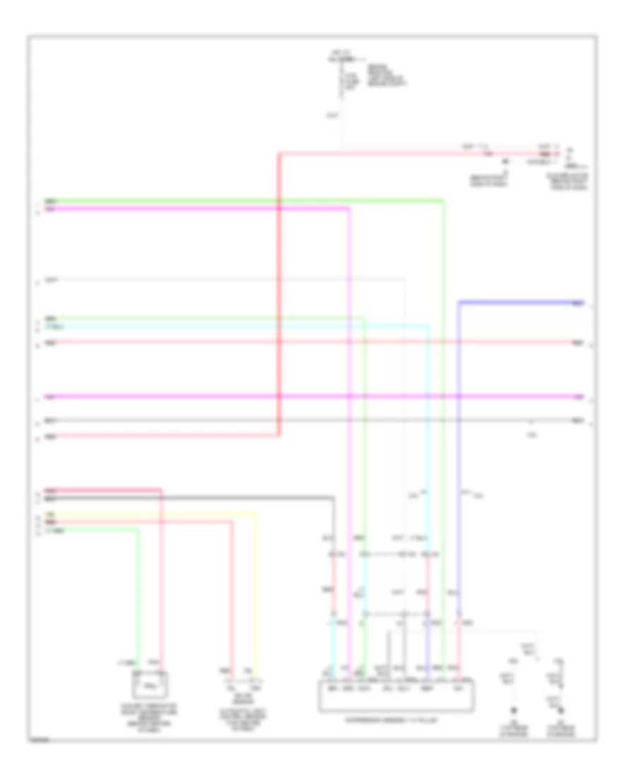
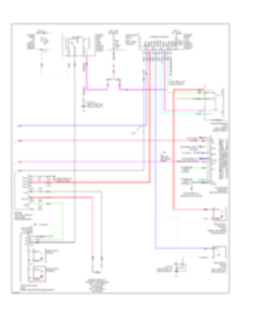
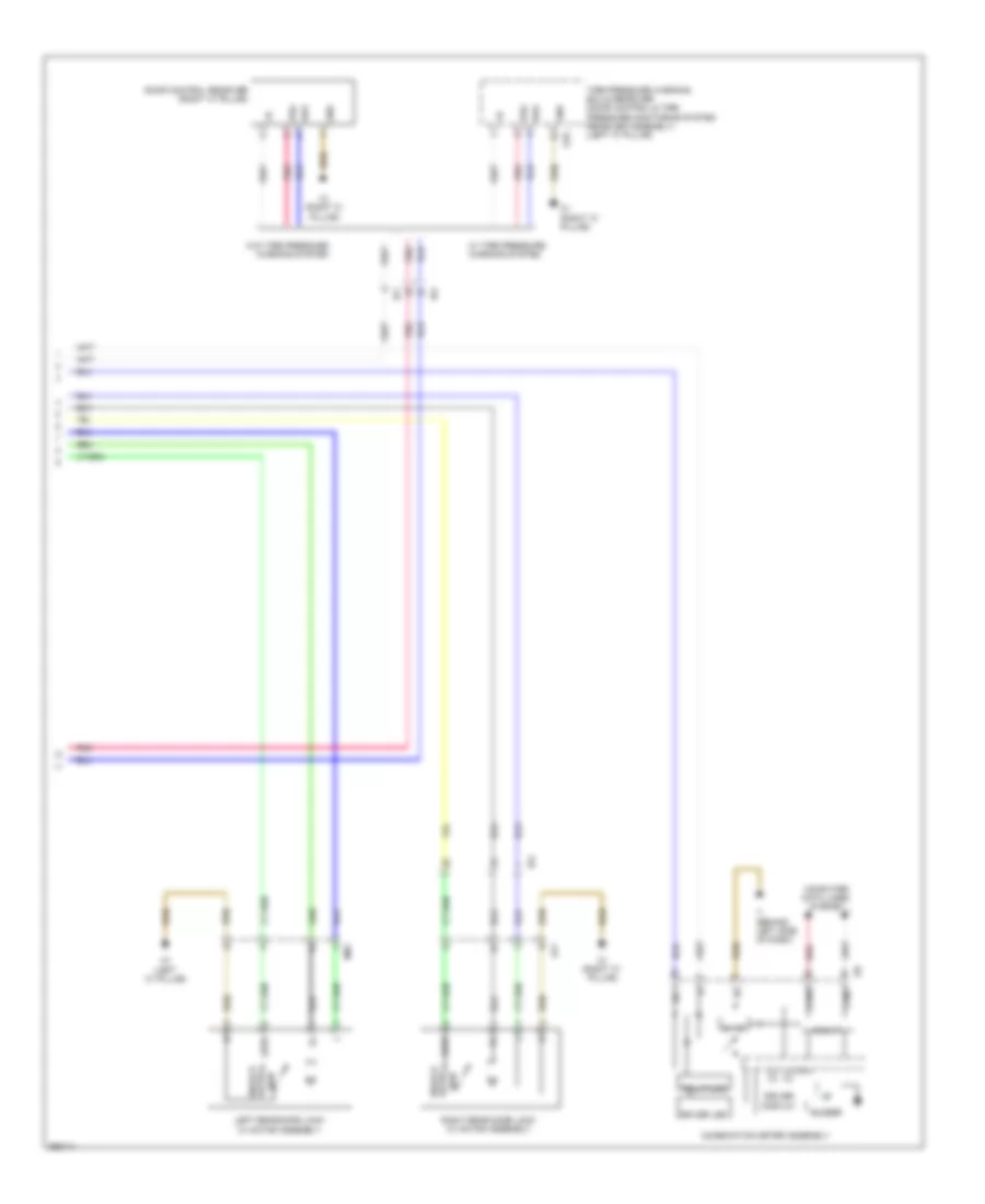
AIR CONDITIONING
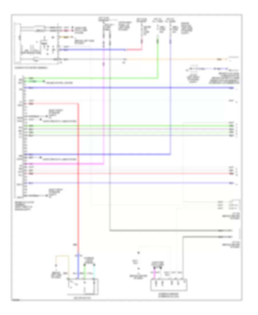
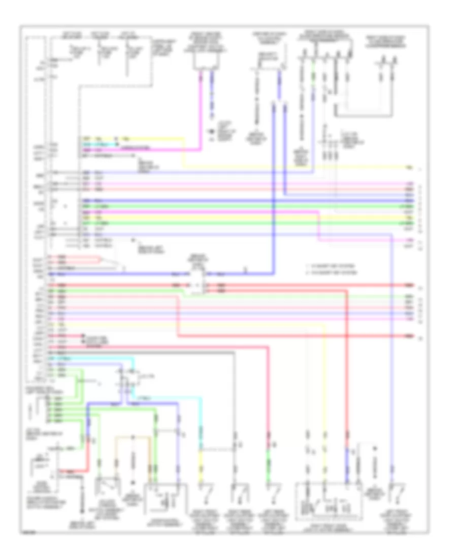
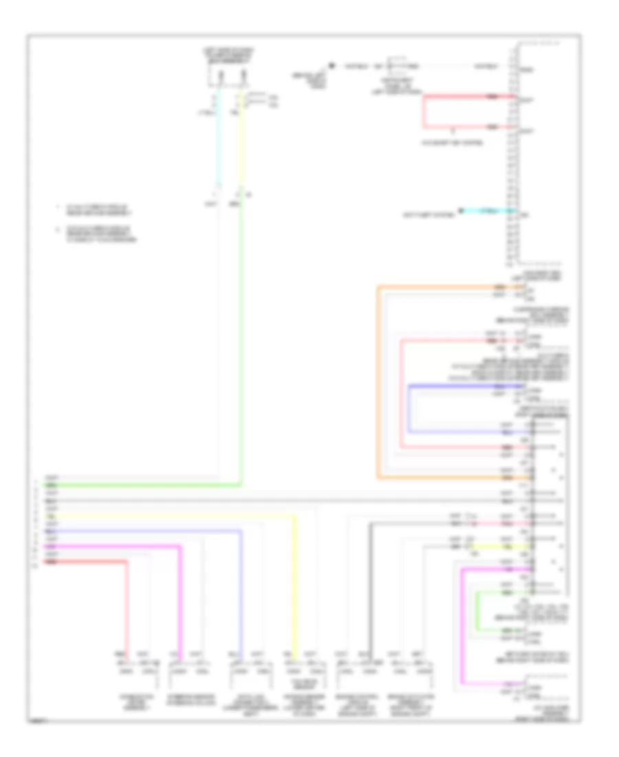
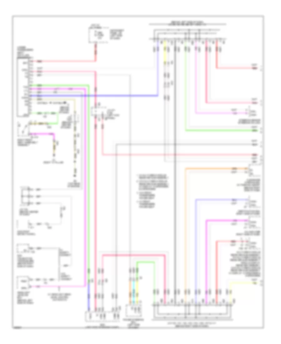
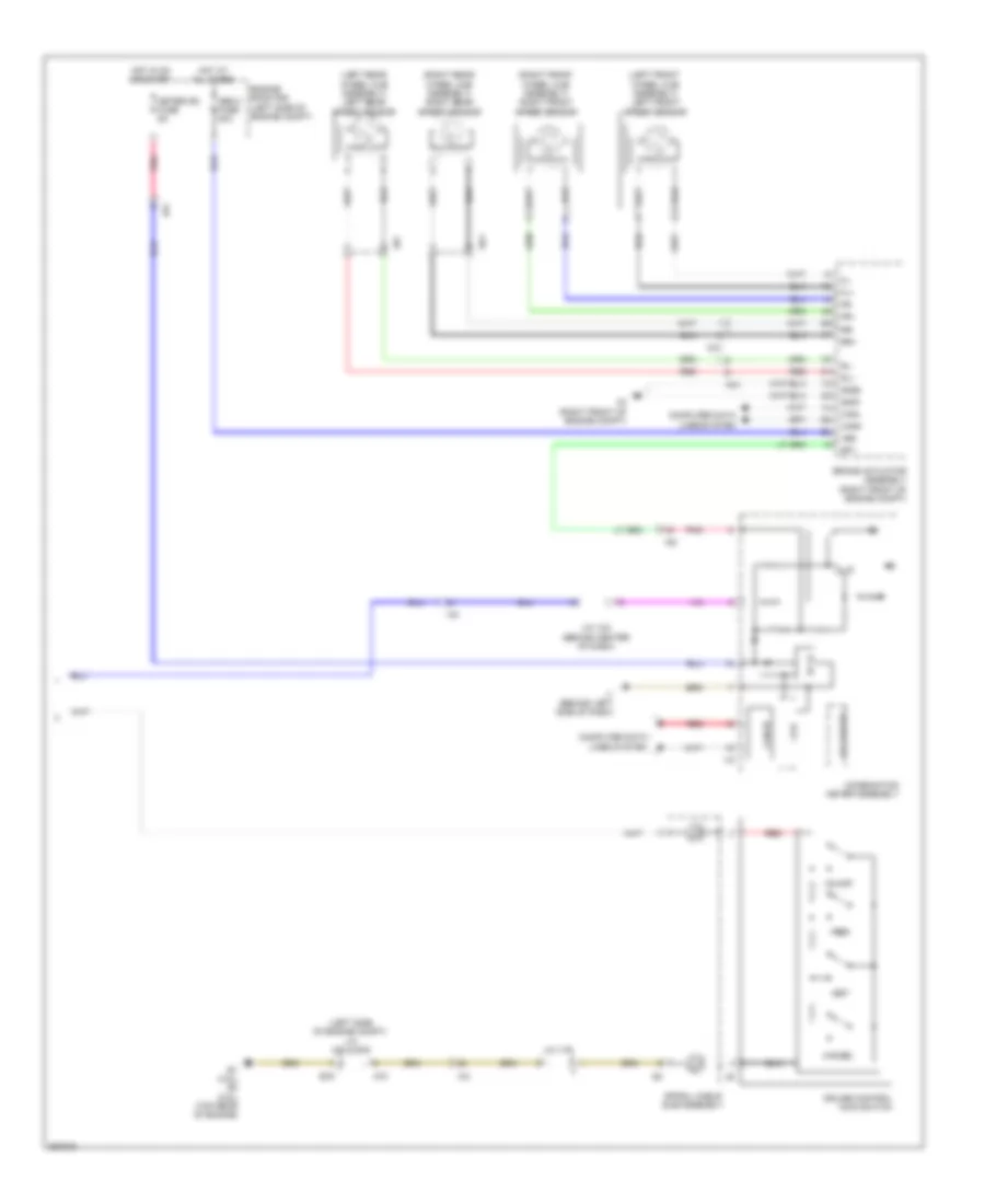
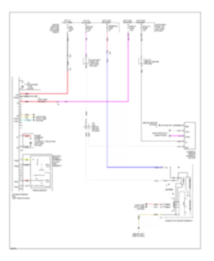
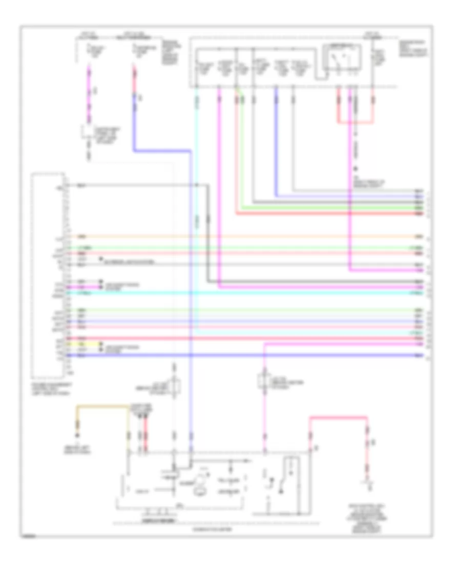
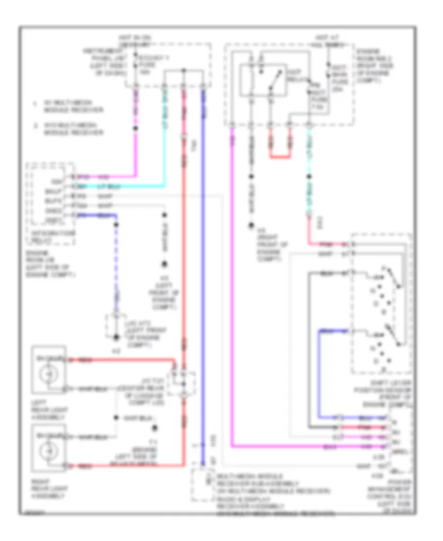
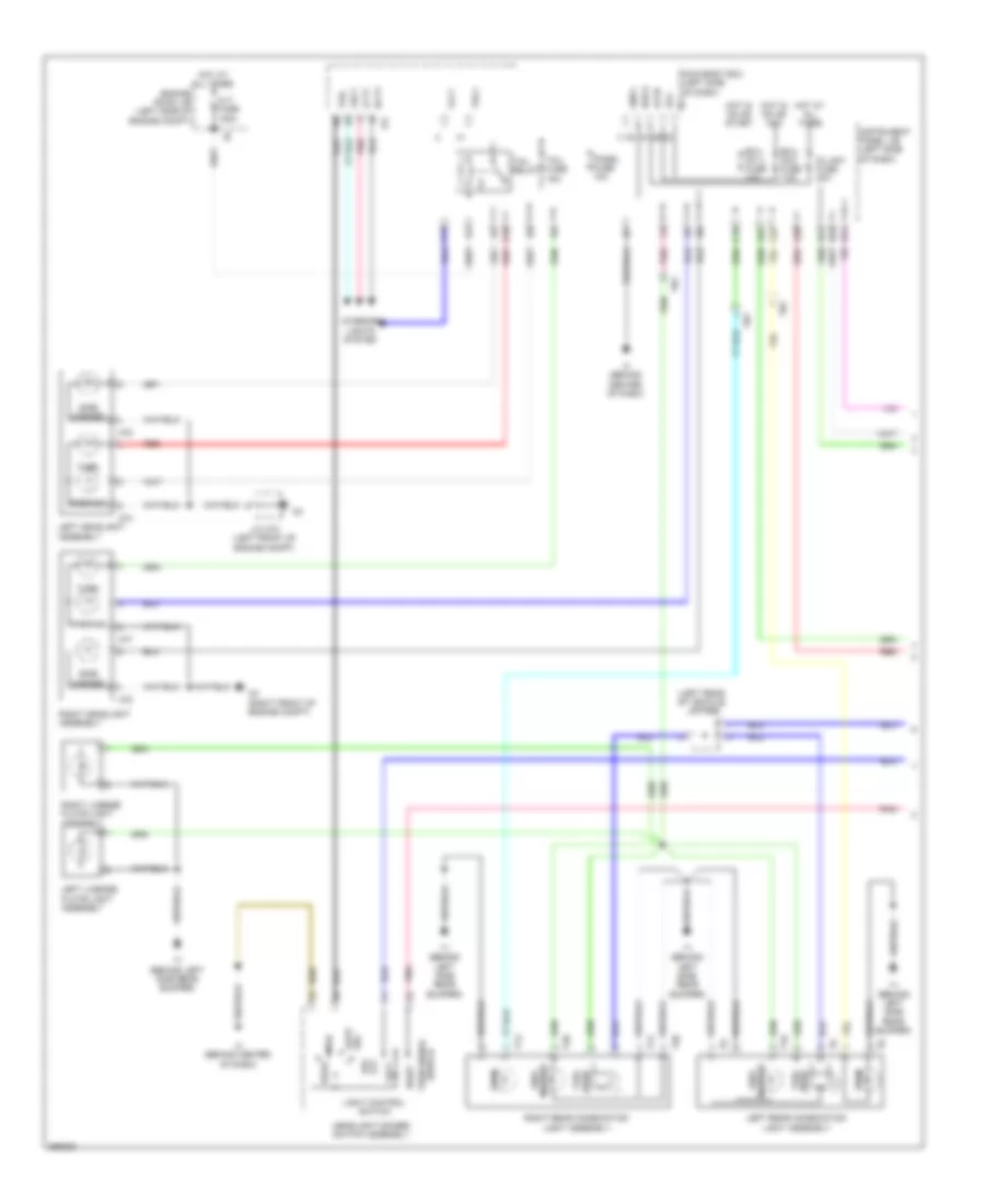
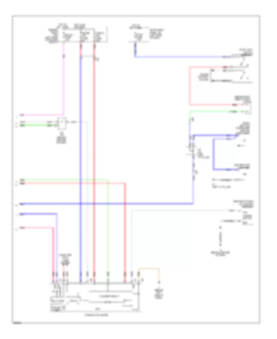
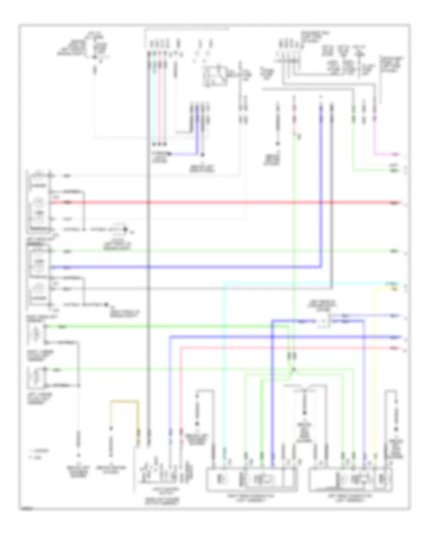
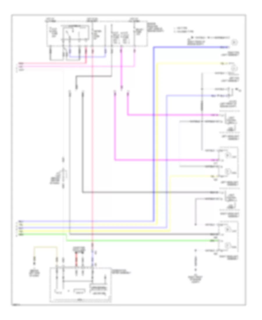
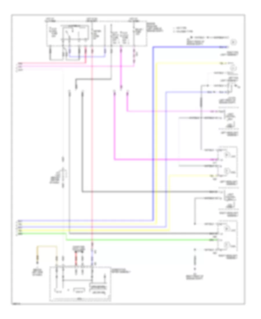
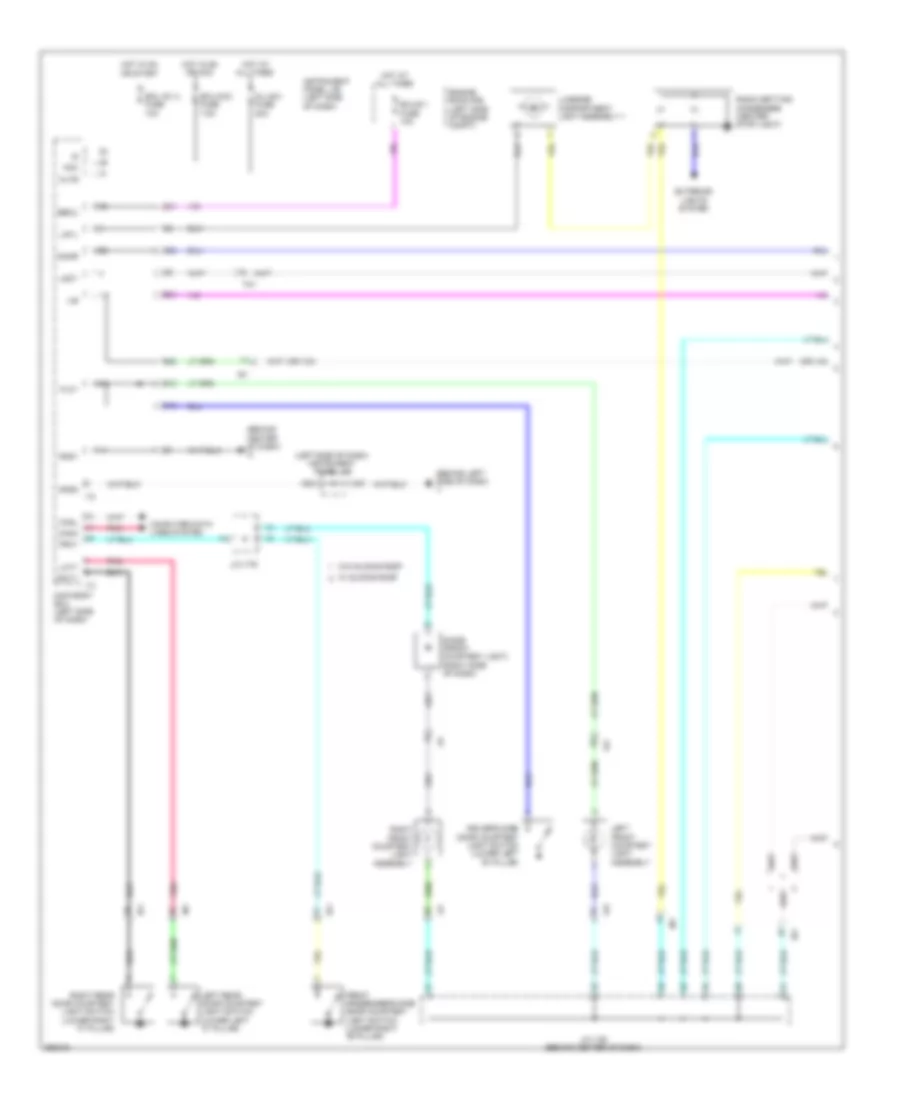
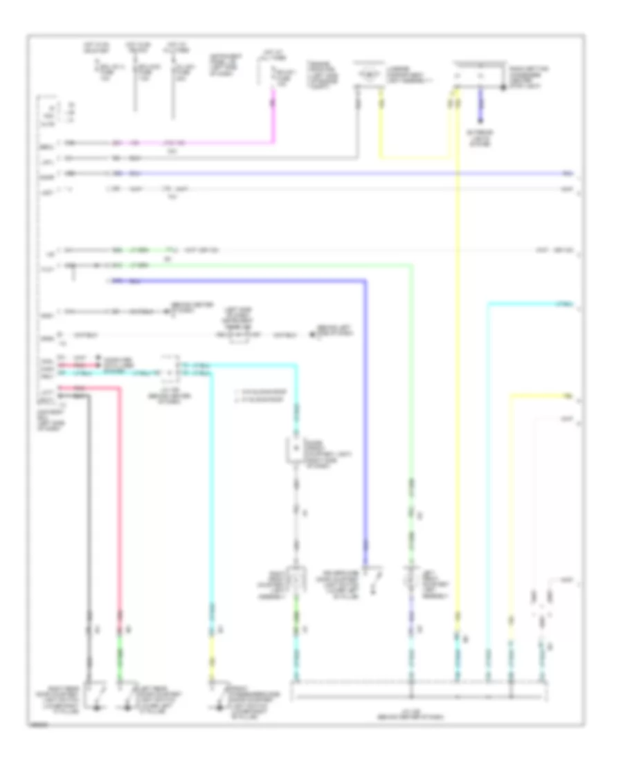
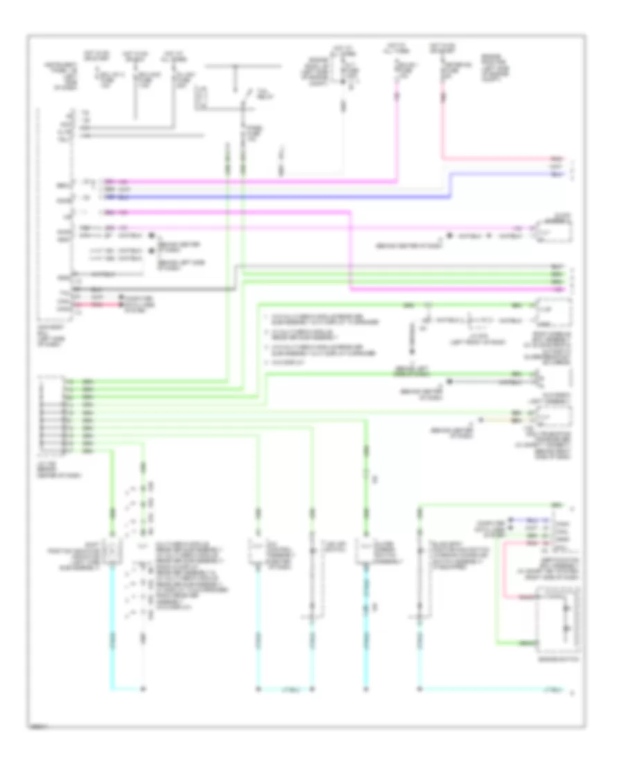
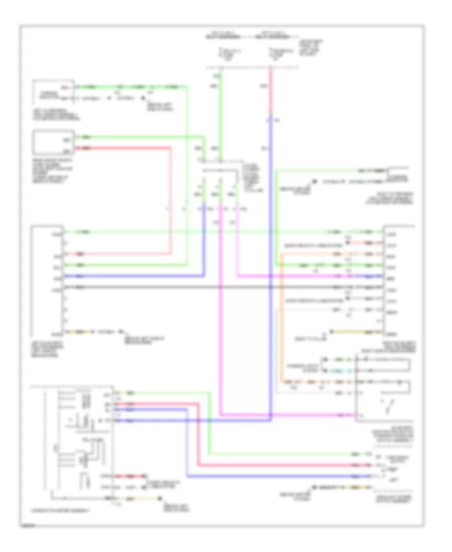
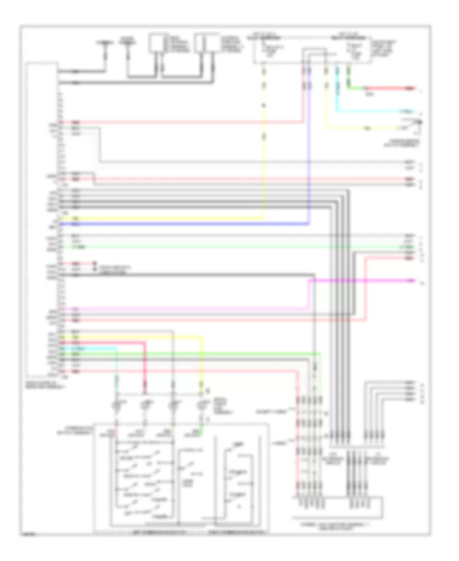
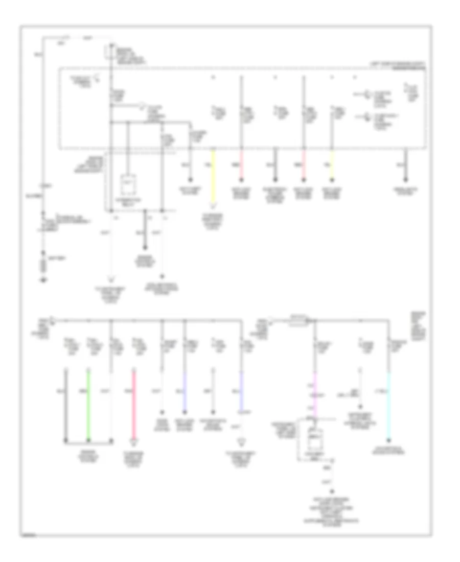
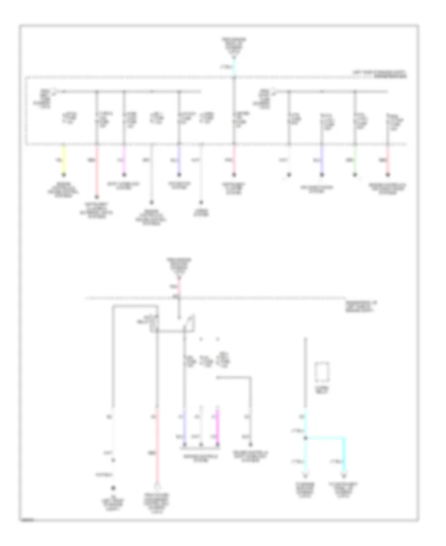
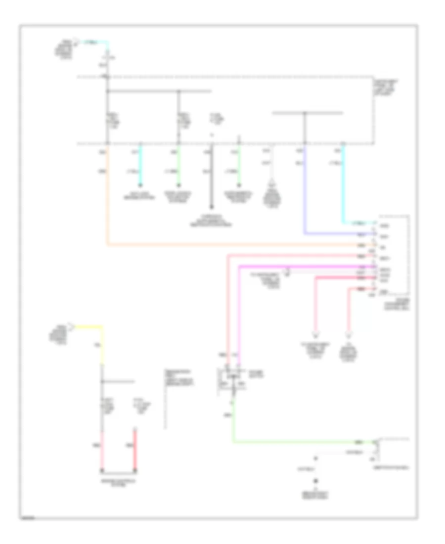
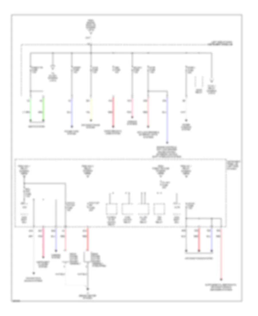
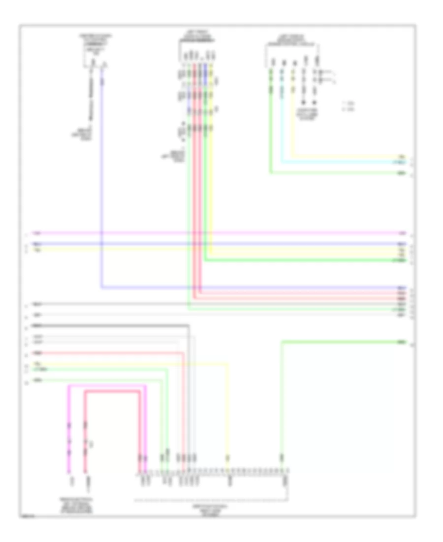
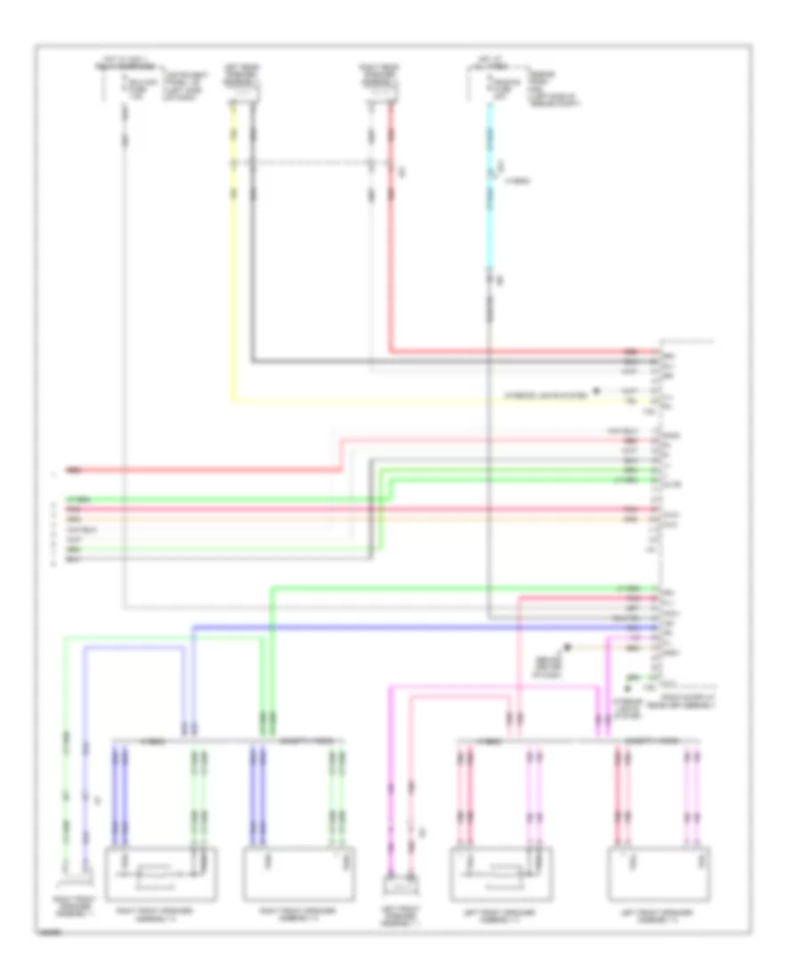
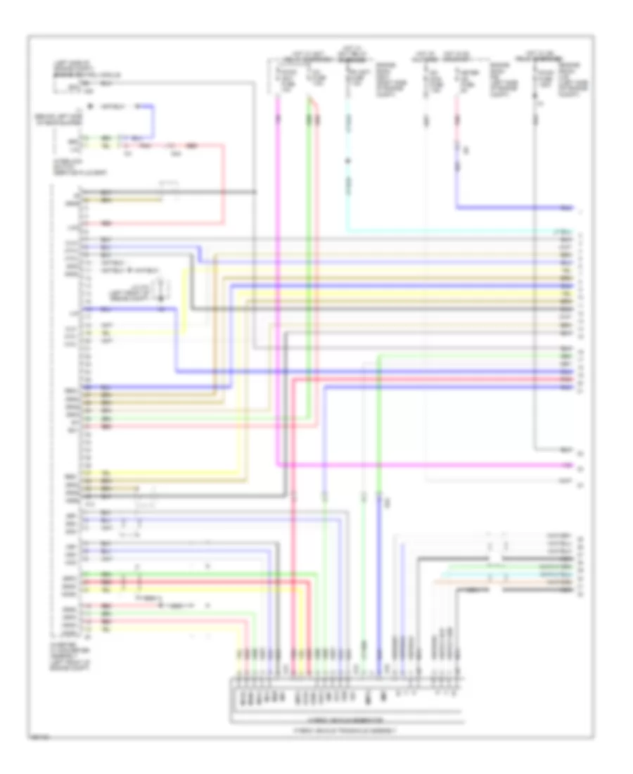
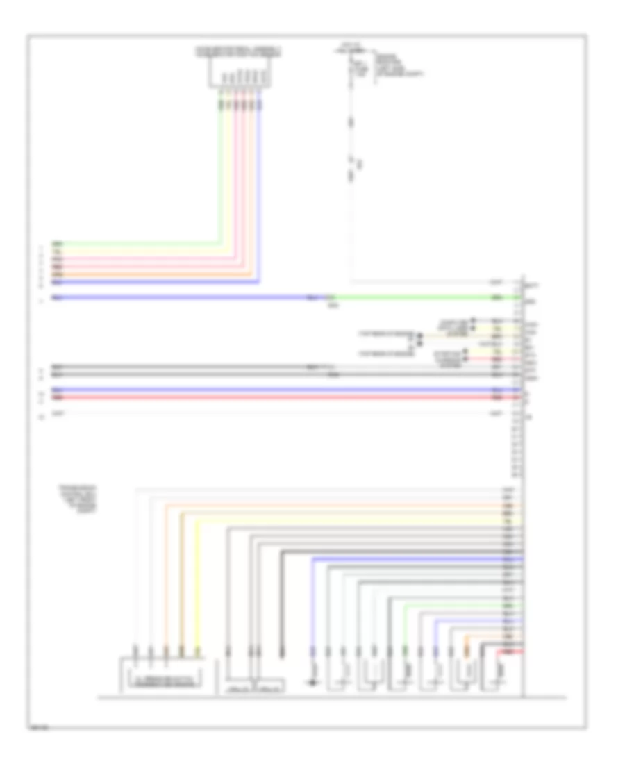
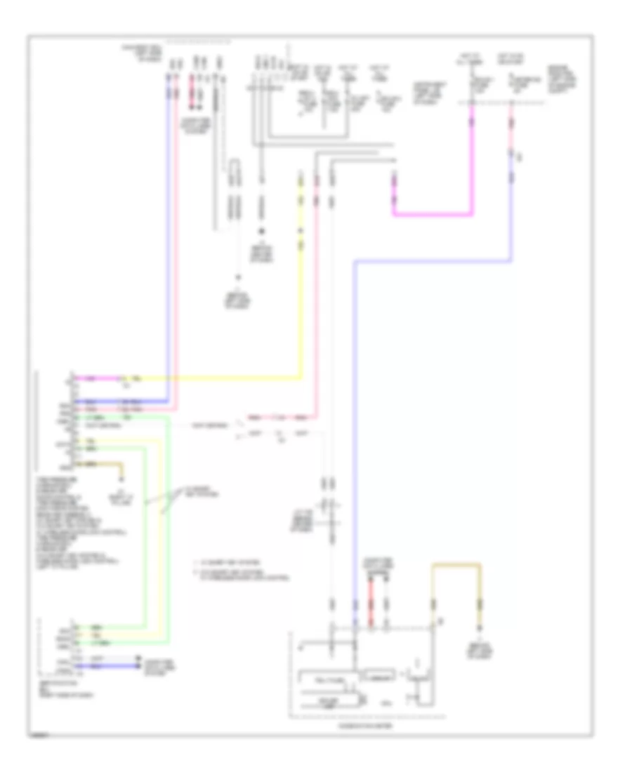
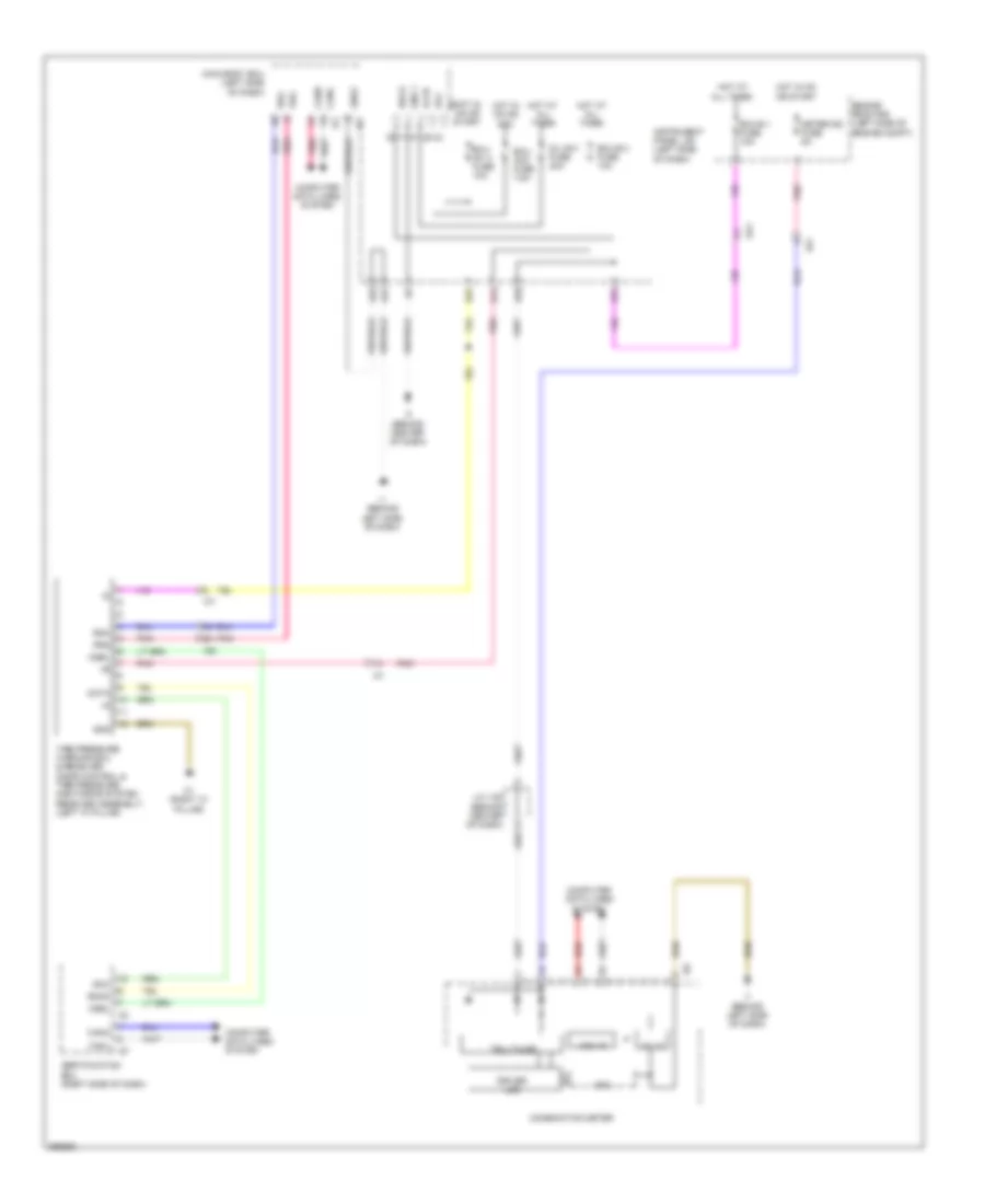
Automatic A/C Wiring Diagram, Except Hybrid (1 of 3) for Toyota Camry LE 2014
 https://portal-diagnostov.com/license.html
Automotive Electricians Portal FZCO
Automotive Electricians Portal FZCO
https://portal-diagnostov.com/license.html
https://portal-diagnostov.com/license.html
Automotive Electricians Portal FZCO
Automotive Electricians Portal FZCO
List of elements for Automatic A/C Wiring Diagram, Except Hybrid (1 of 3) for Toyota Camry LE 2014:
- (front center of engine compt) ambient temperature sensor (thermistor assembly)
- (right front of engine compt) a/c pressure sensor (a/c tube & accessory assembly)
- 3.5l
- A/c amplifier (right side of dash)
- A/c evaporator temperature sensor
- A/c unit (a/c harness assembly)
- A/c-b fuse 7.5a
- A/c-ig1 fuse 7.5a
- A70
- B bus
- B21
- B22
- B39
- Blw
- Bus
- Bus g
- Canh
- Canl
- Computer data lines system
- Connector housing color (black)
- Connector housing color (green)
- Connector housing color (red)
- Damper servo motor (air inlet)
- Damper servo motor (air vent mode)
- Damper servo motor (left front side air mix)
- Damper servo motor (right front side air mix)
- Defogger system
- E76
- Floq
- Gnd
- Hot at all times
- Hot in on or start
- I5 (behind right side of dash)
- I77
- Ia8
- Ig+
- Instrument panel j/b (left side of dash)
- J/c a70 & e76 (left side of engine compt)
- Lin1
- Lock
- Mgc
- Pnk
- Pre
- Rdfg
- Red
- S5-1
- S5-3
- Sg-1
- Sga
- Sig-2
- Sol+
- Tam
- Tea
- Tsd
- Tsp
- W/ smart key system
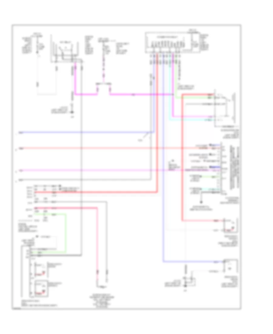
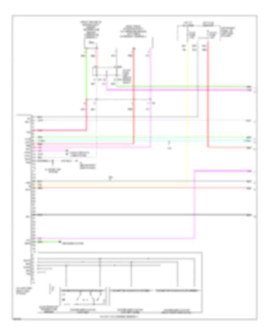
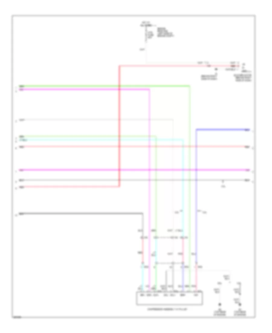
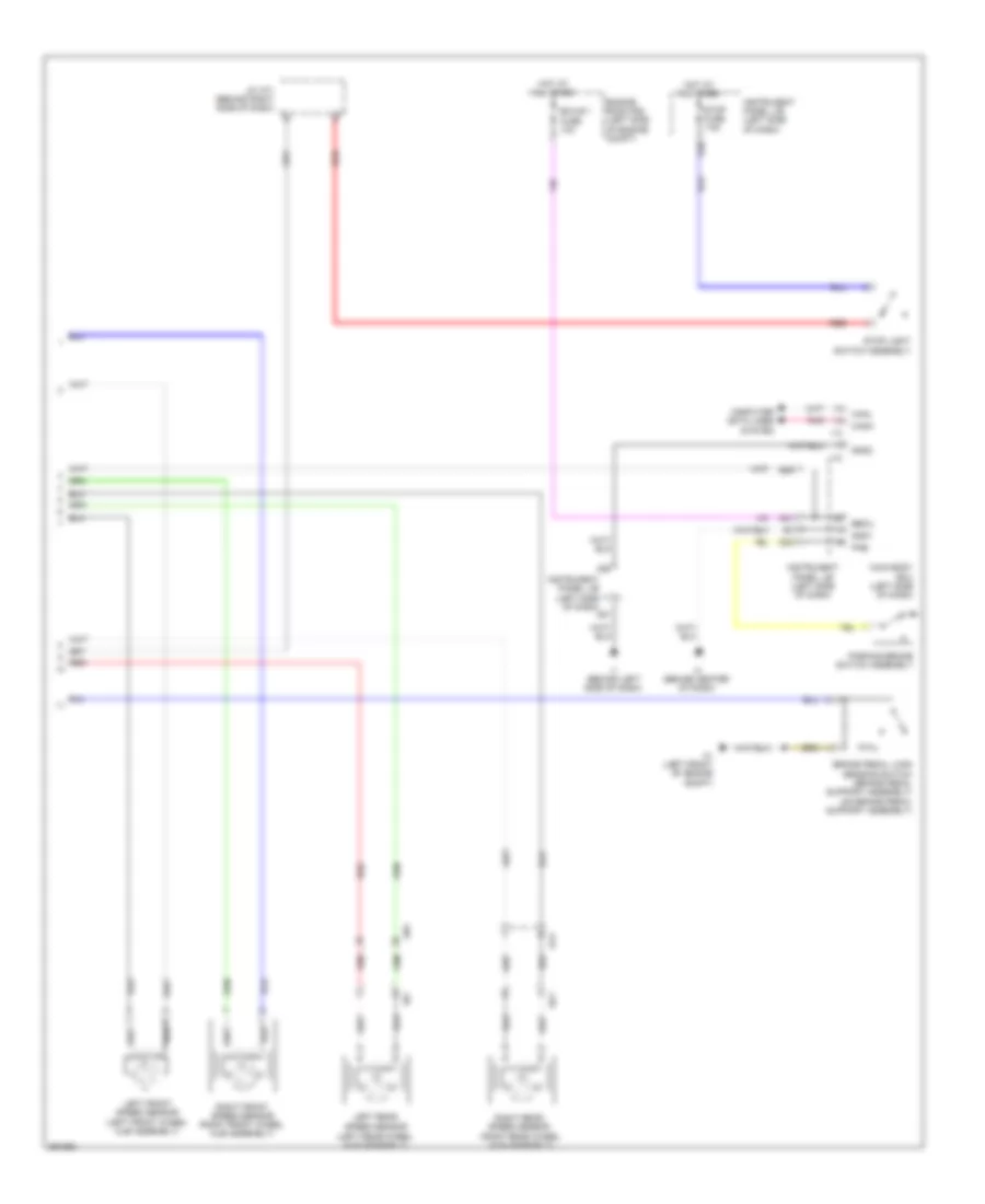
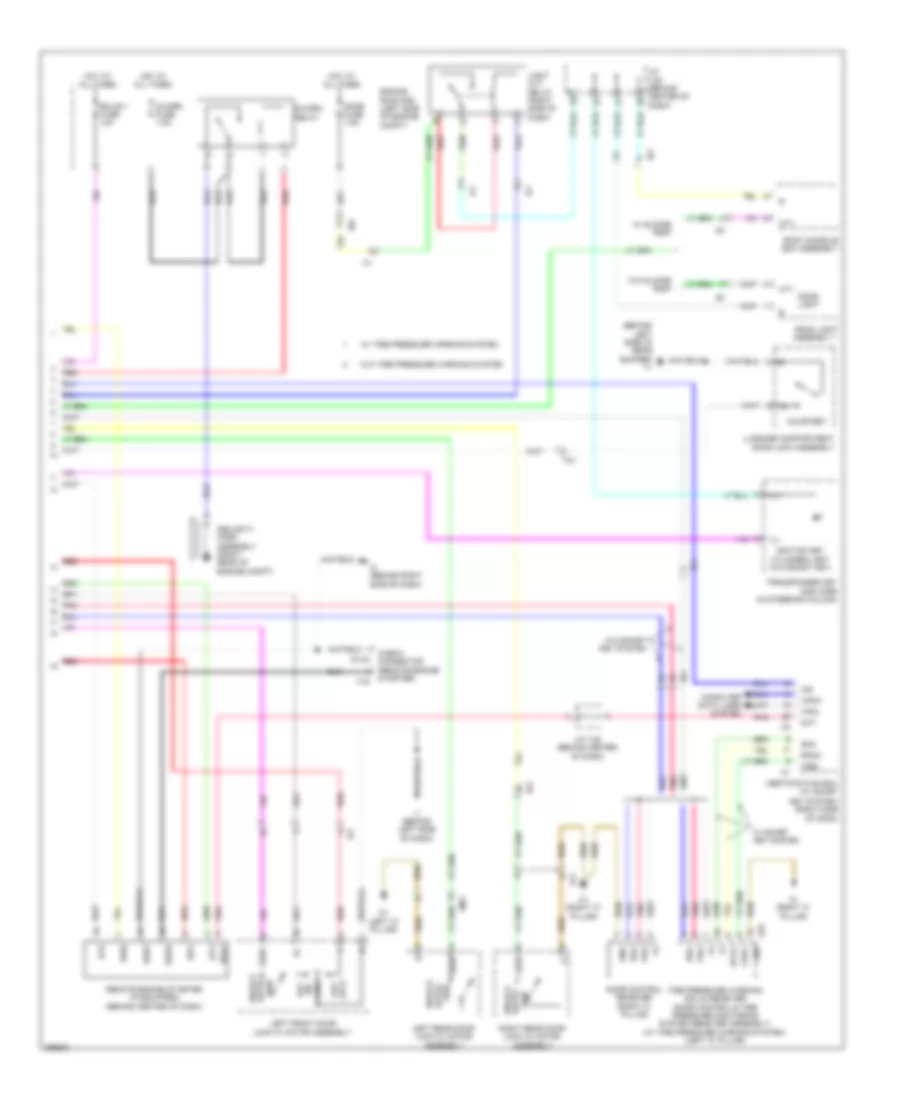
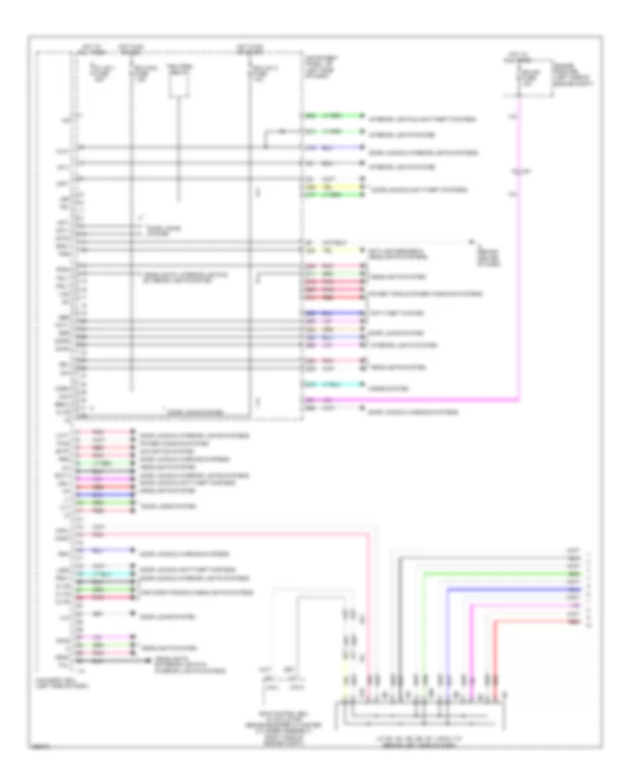
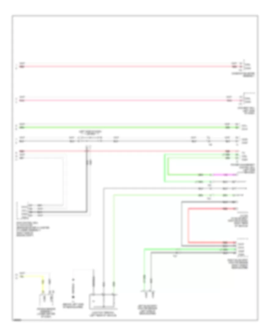
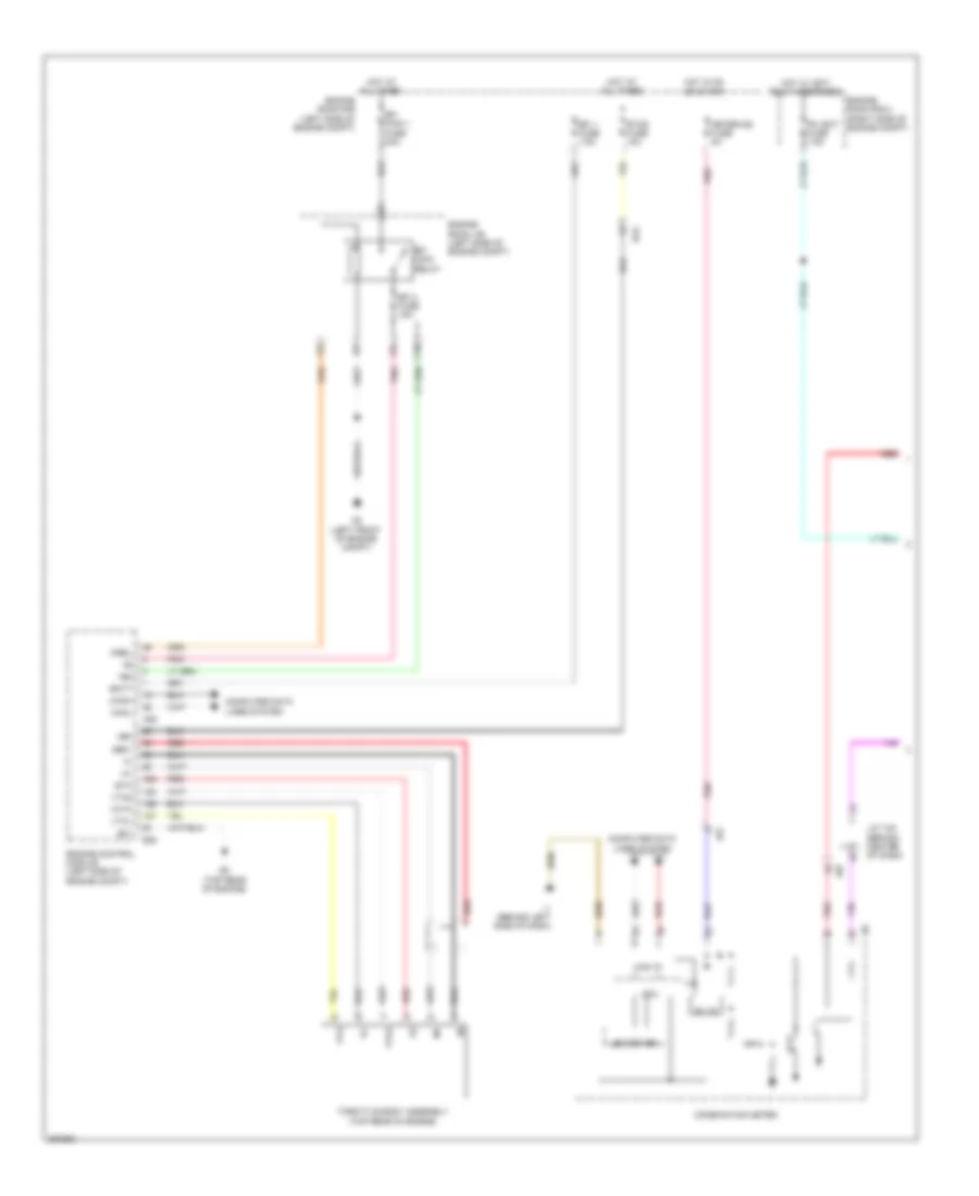
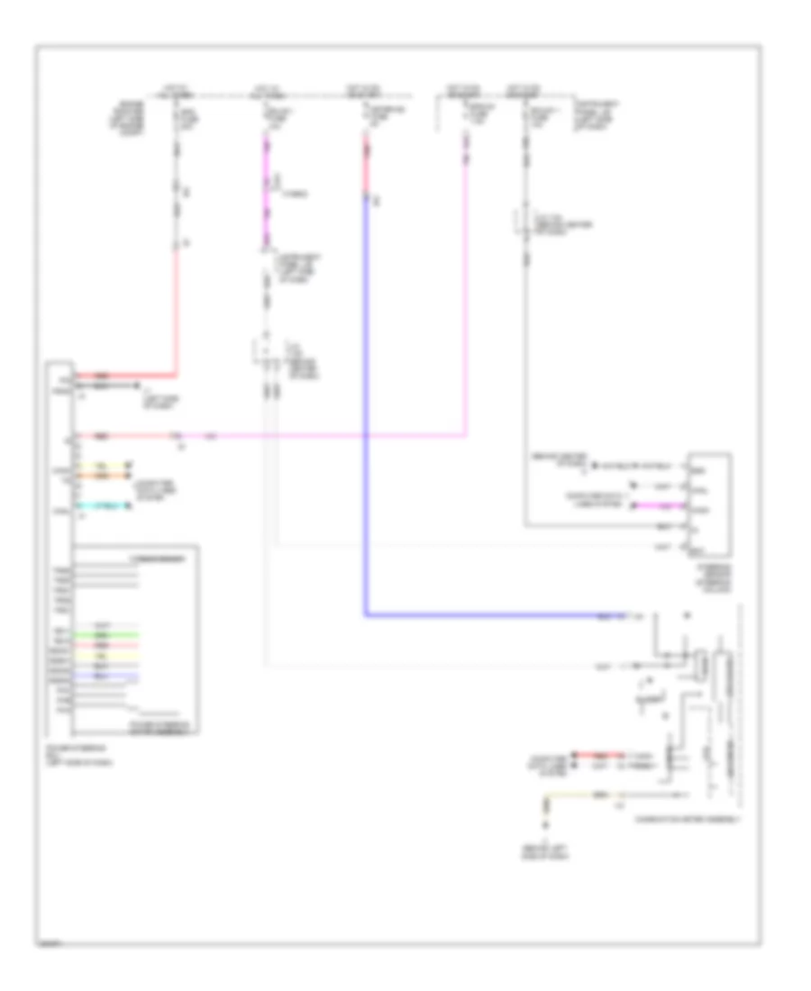
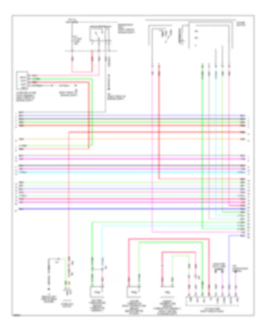
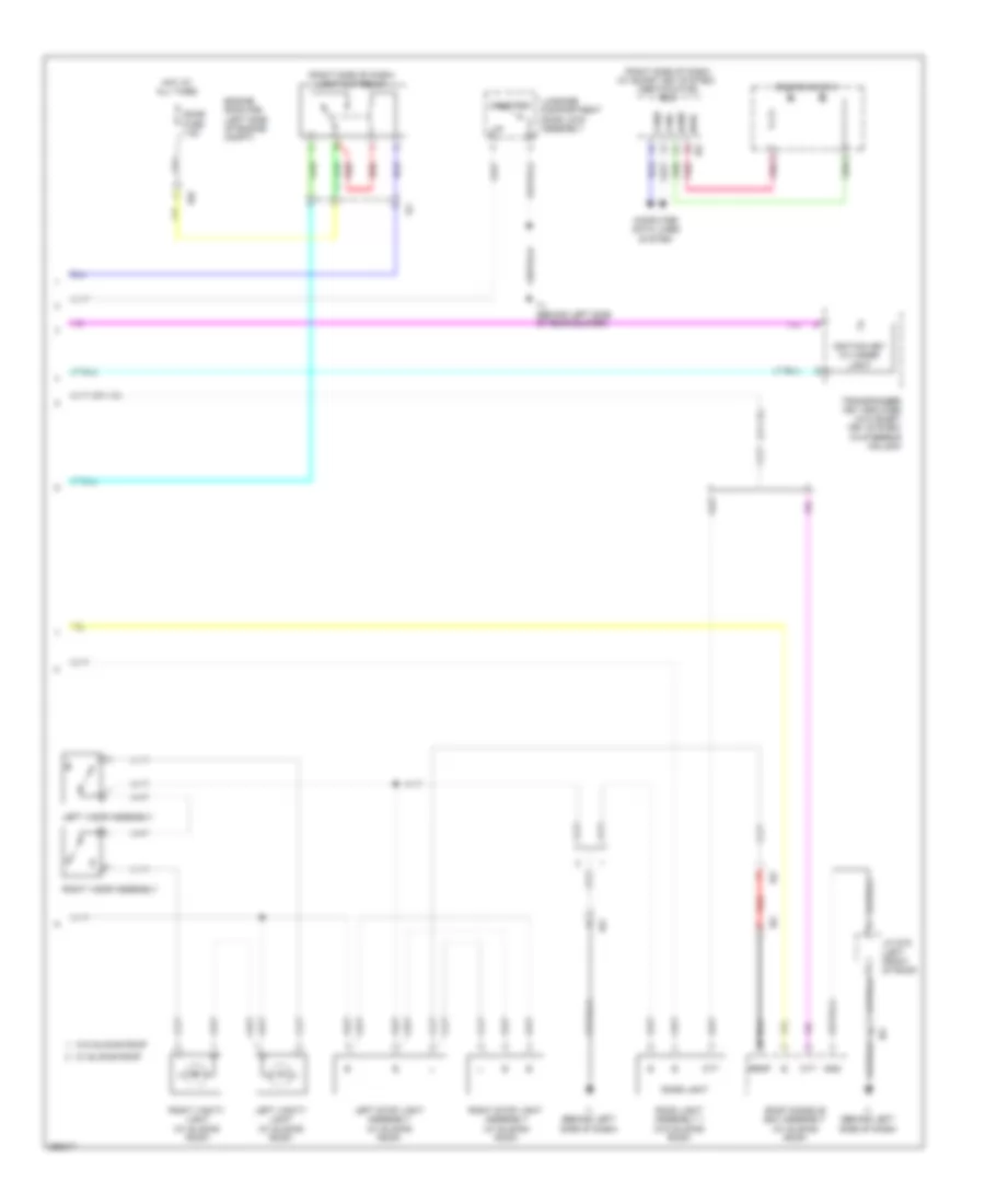
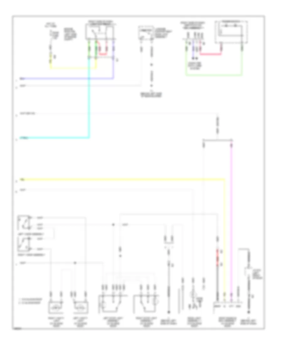
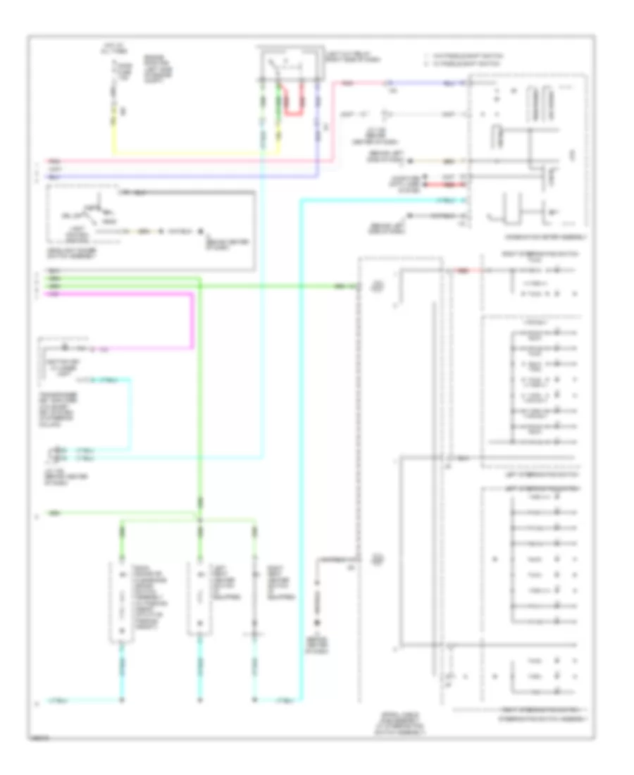
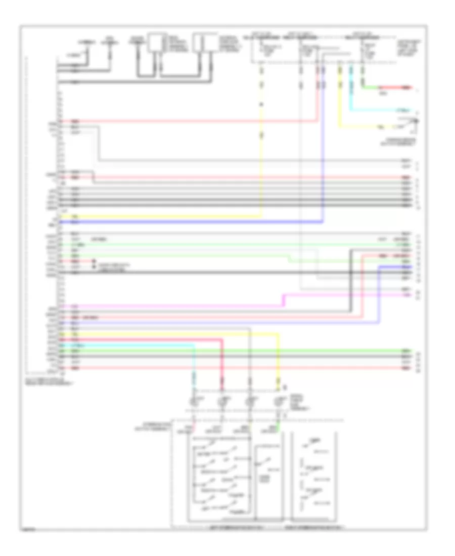
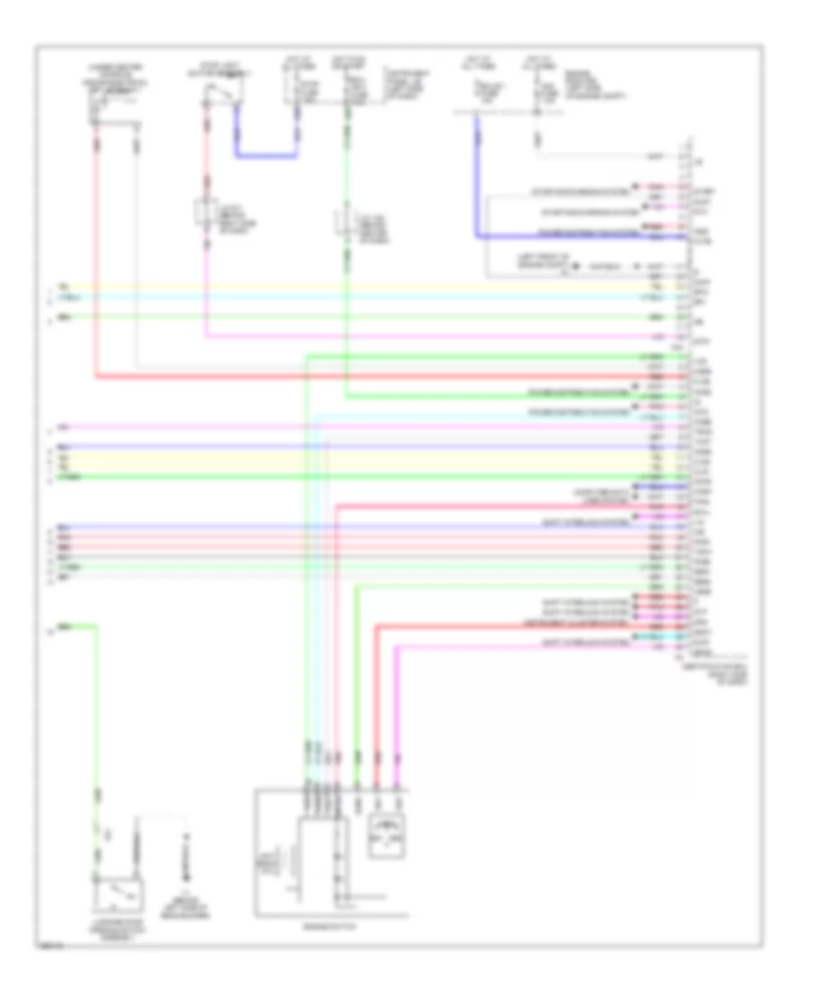
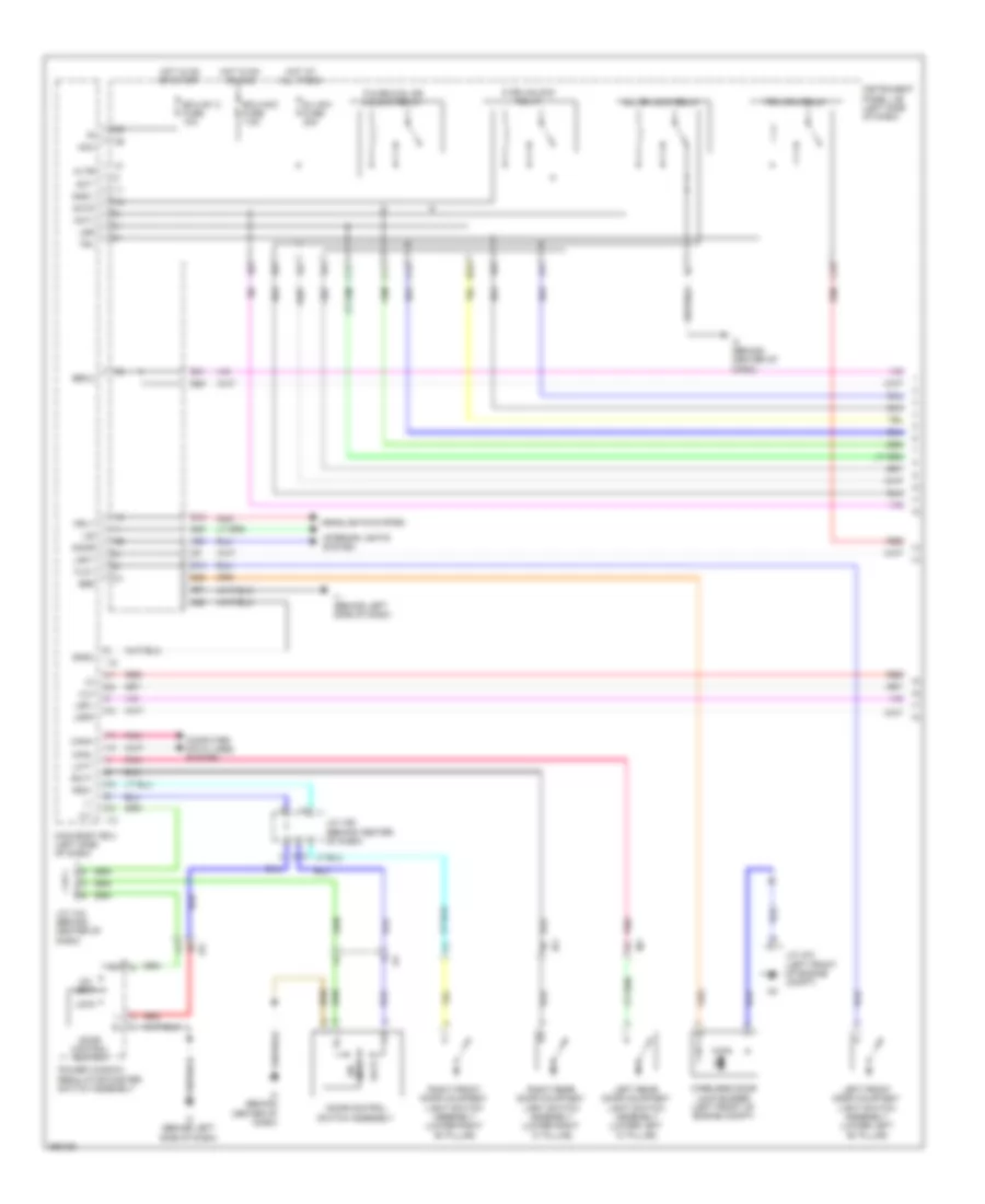
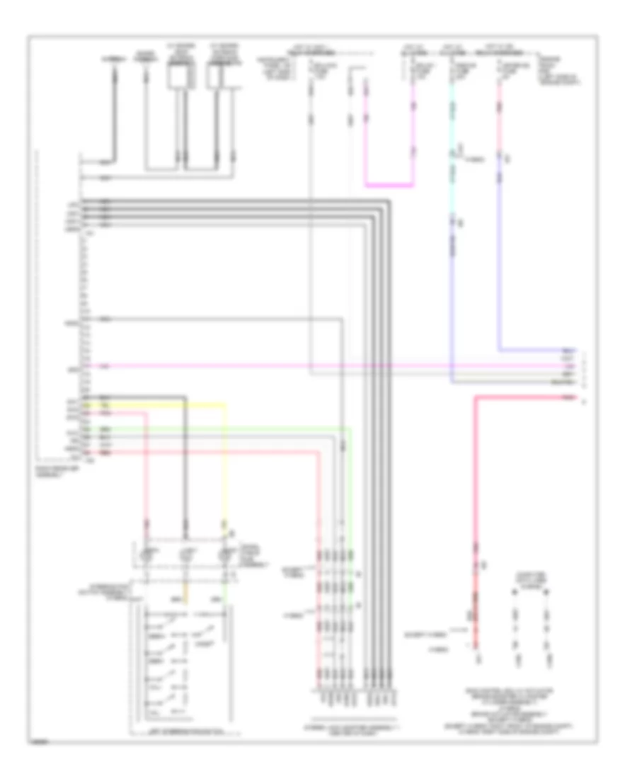
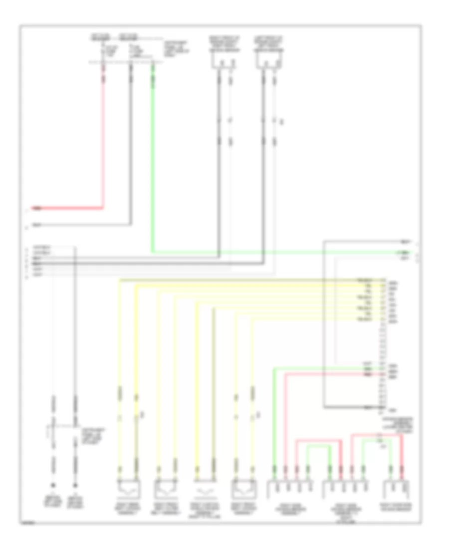
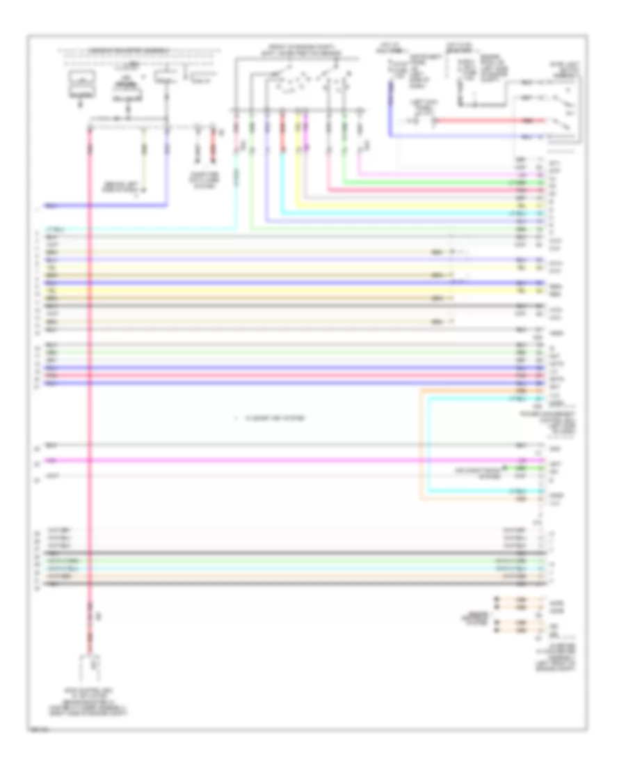
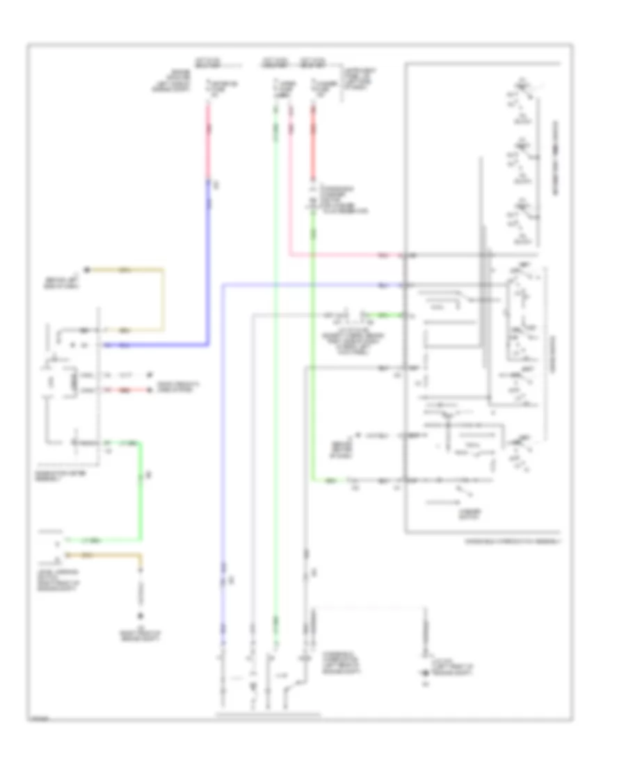
Automatic A/C Wiring Diagram, Except Hybrid (2 of 3) for Toyota Camry LE 2014
List of elements for Automatic A/C Wiring Diagram, Except Hybrid (2 of 3) for Toyota Camry LE 2014:
- 2.5l
- 3.5l
- Automatic light control sensor (top center of dash)
- Blower motor (behind right side of dash)
- Compressor assembly w/ pulley
- Cooler thermistor (room temperature sensor) (behind center of dash)
- E1 (top rear of engine)
- E2 (top rear of engine)
- E73
- E74
- E75
- Ea2
- Engine room r/b (left side of engine compt)
- Gnd
- Hot at all times
- Htr fuse 50a
- I5 (behind right side of dash)
- Ia4
- Ia6
- Ia8
- Mg+
- Pnk
- Qufl
- Red
- S5fl
- Sgfl
- Sol+
- Sol-
- Solar sensor
- Ssr+
- Tsl
- Tsr
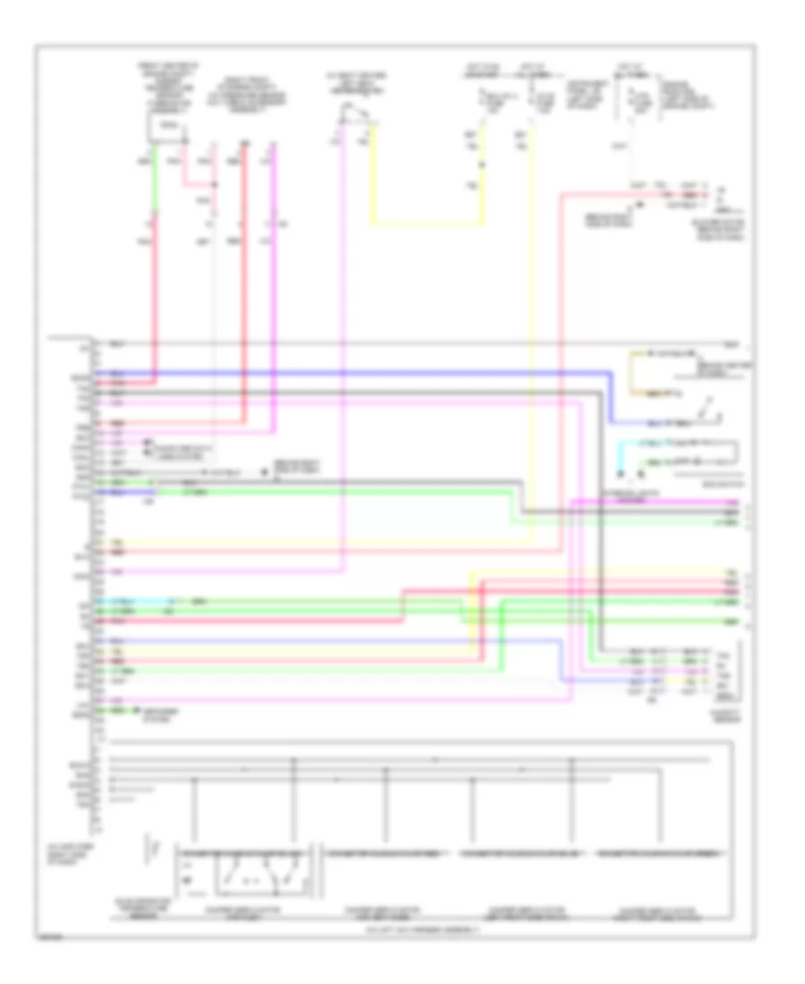
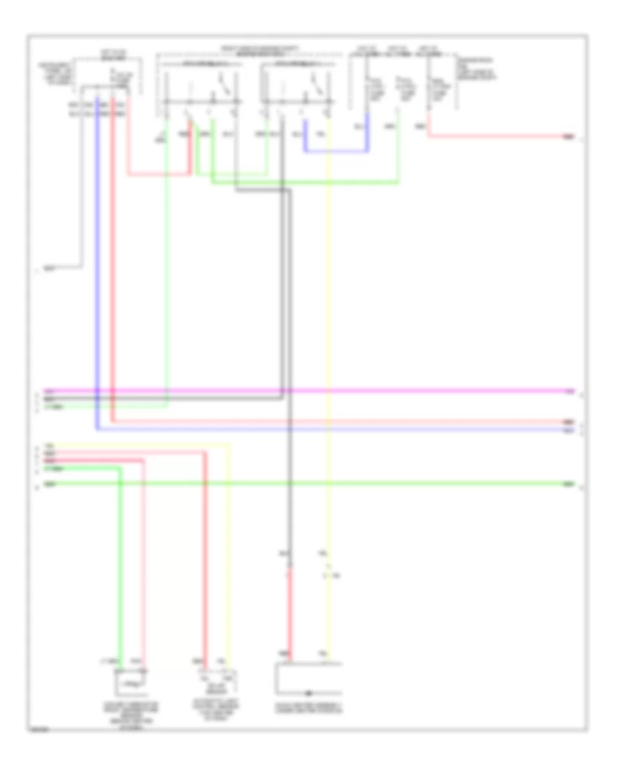
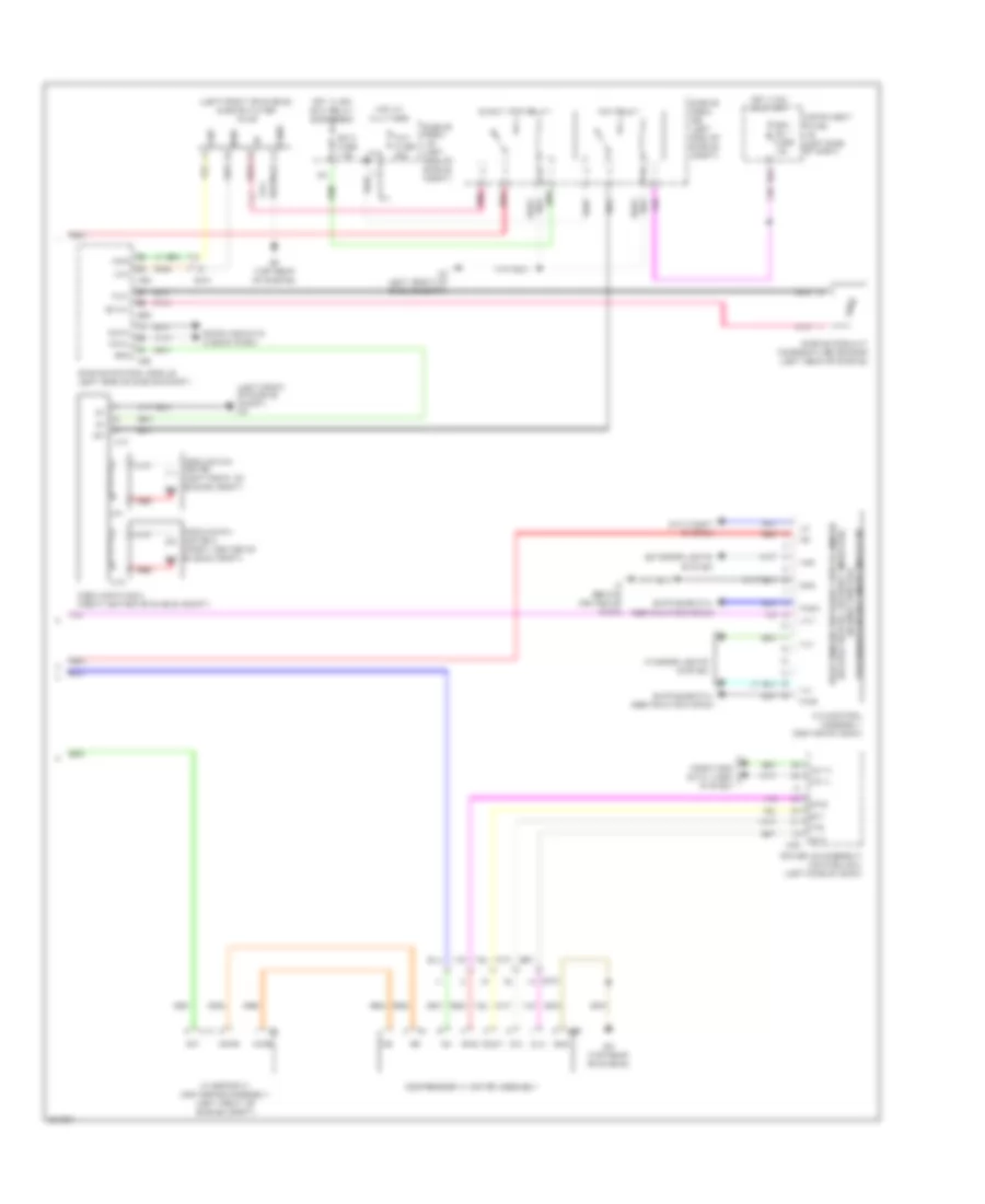
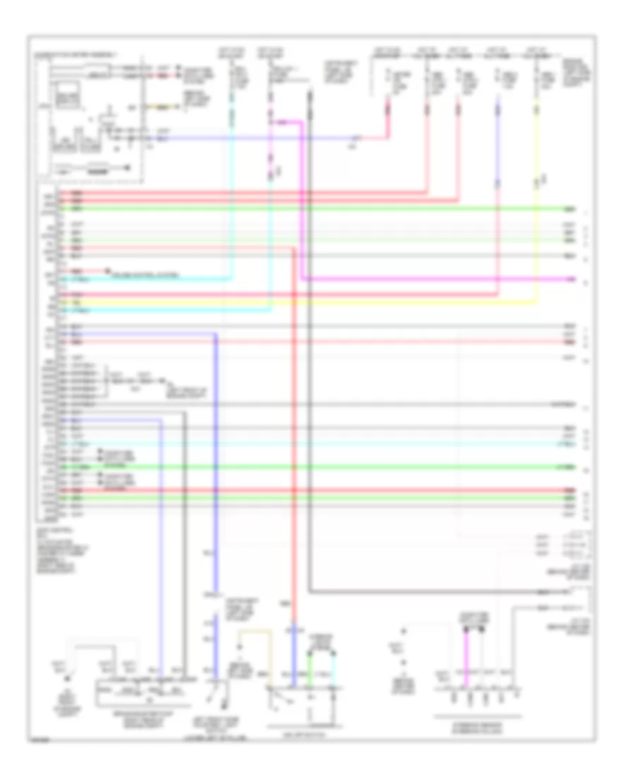
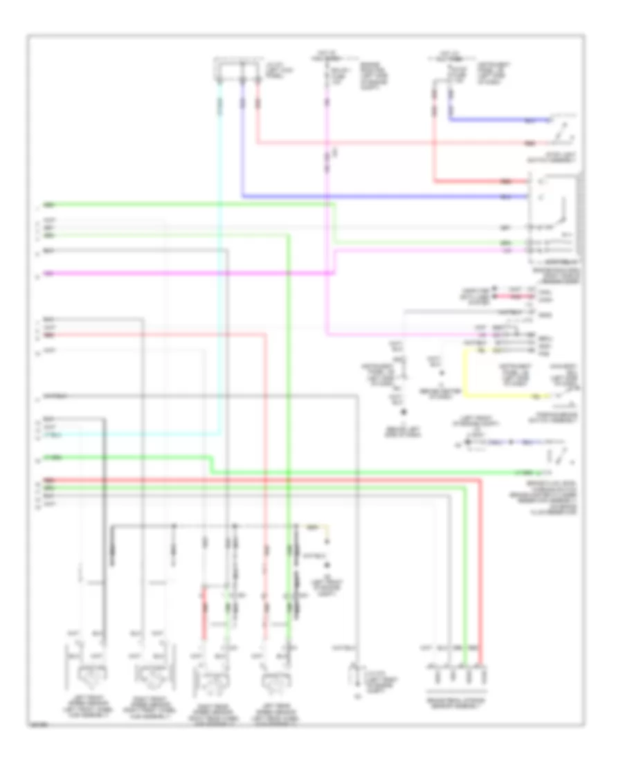
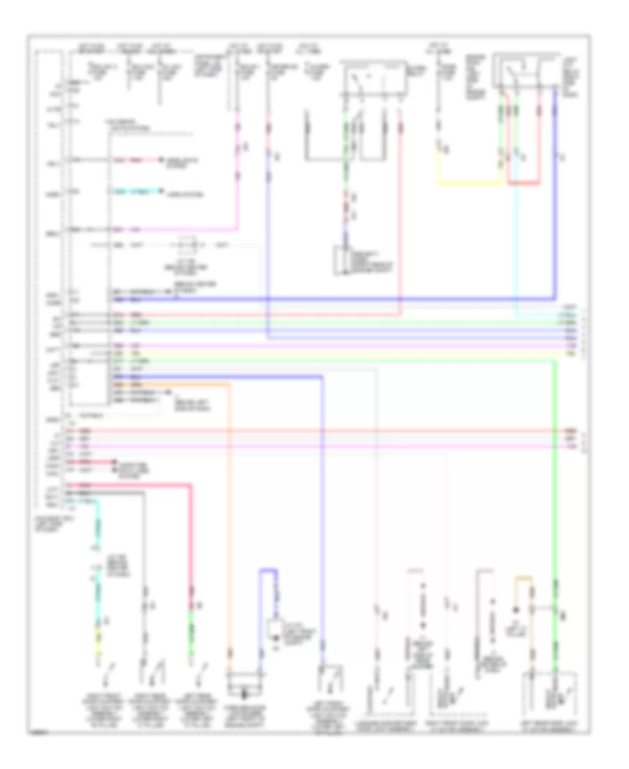
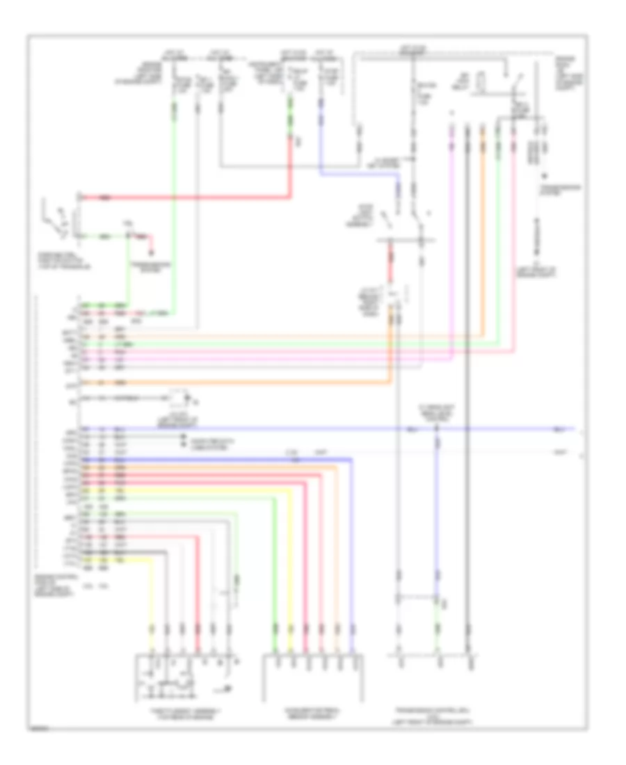
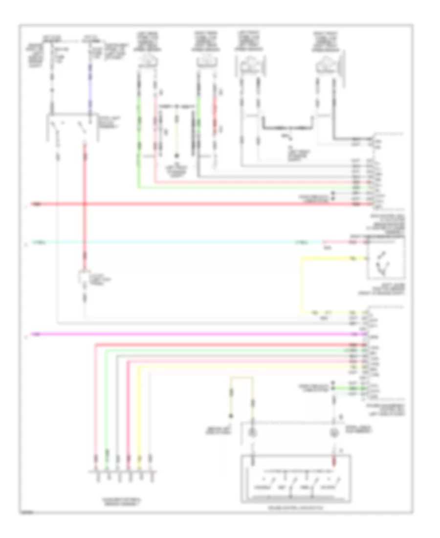
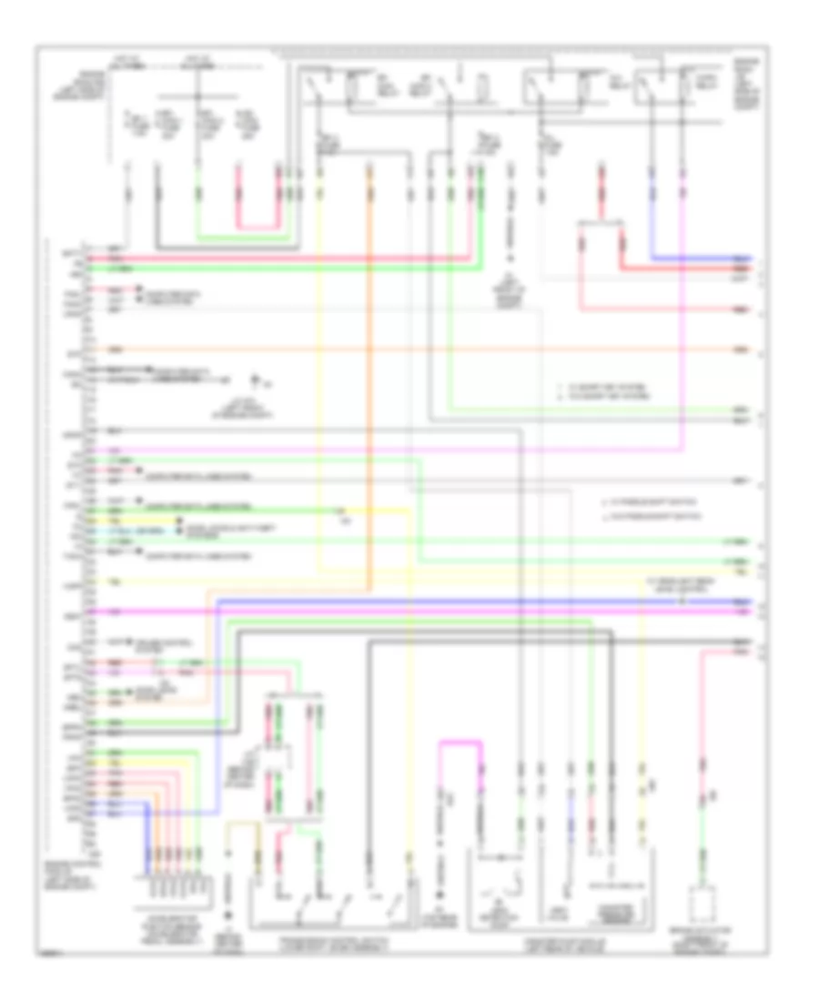
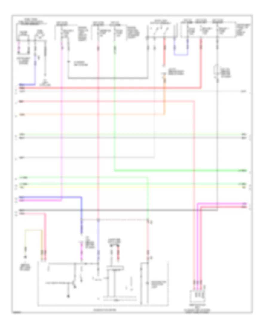
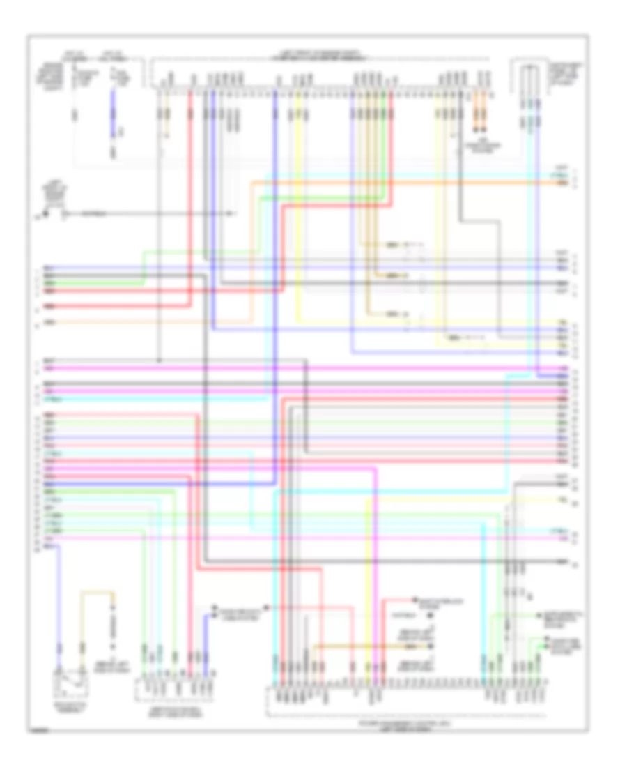
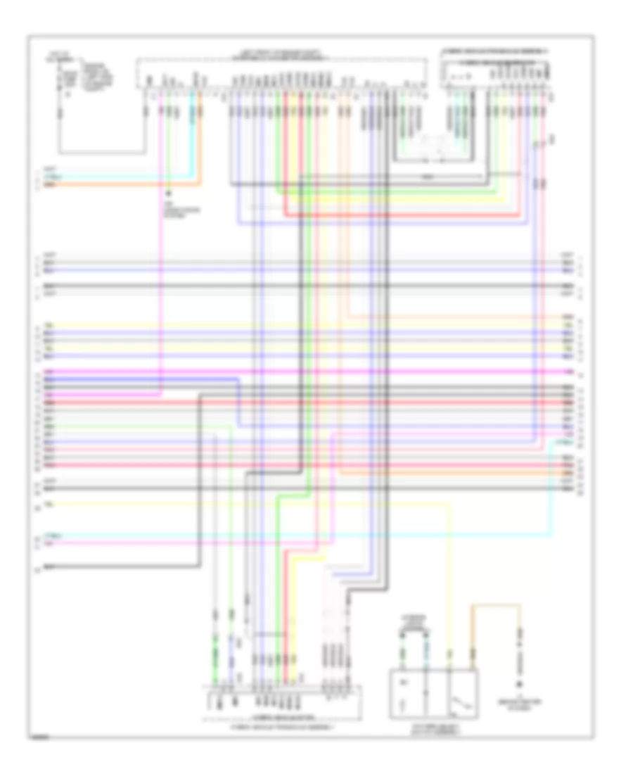
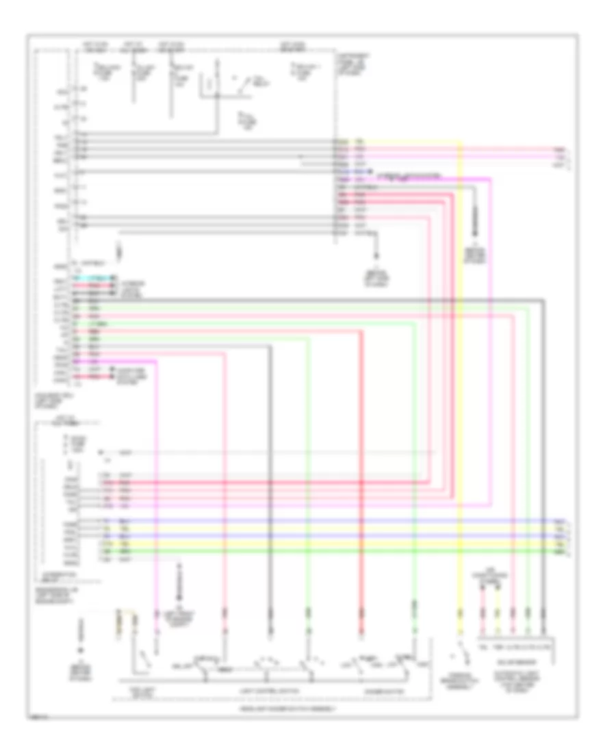
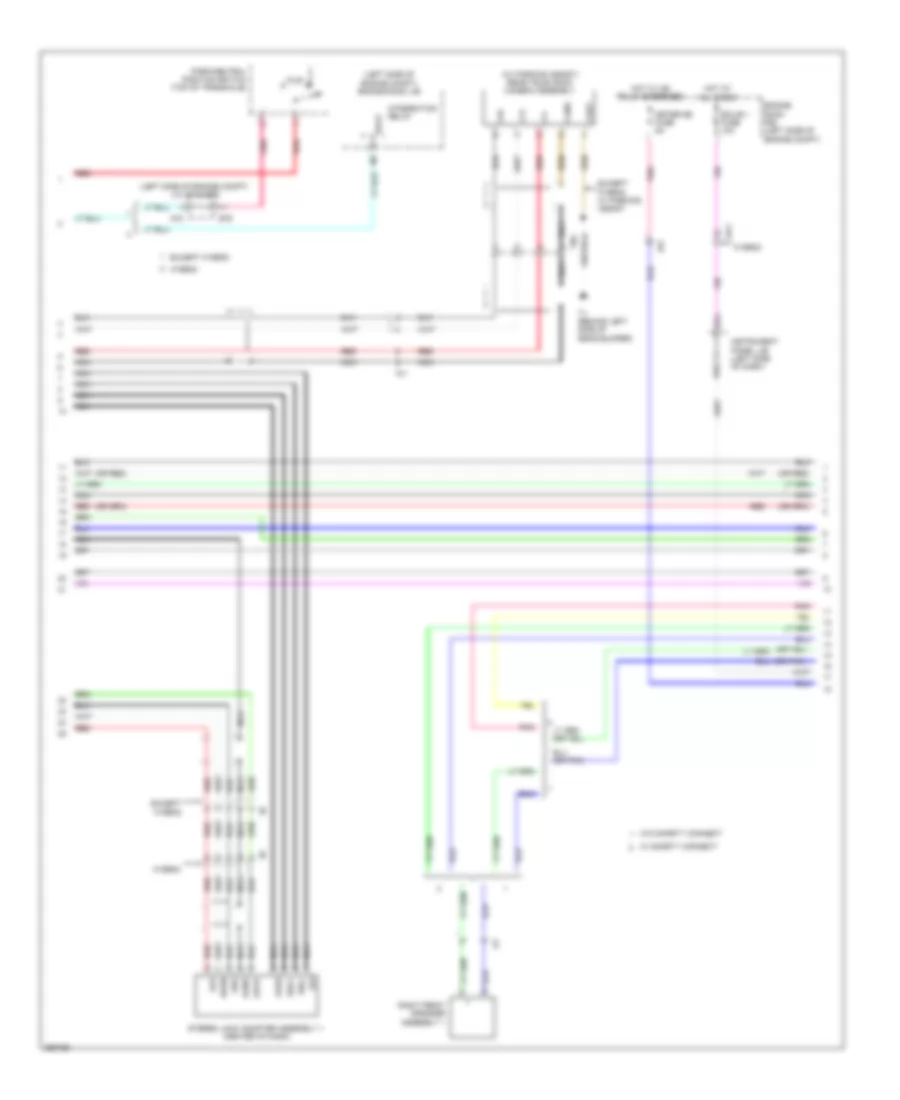
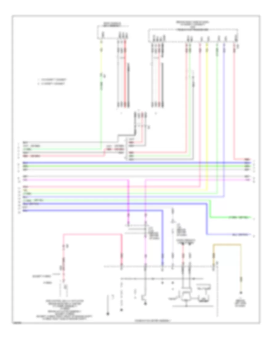
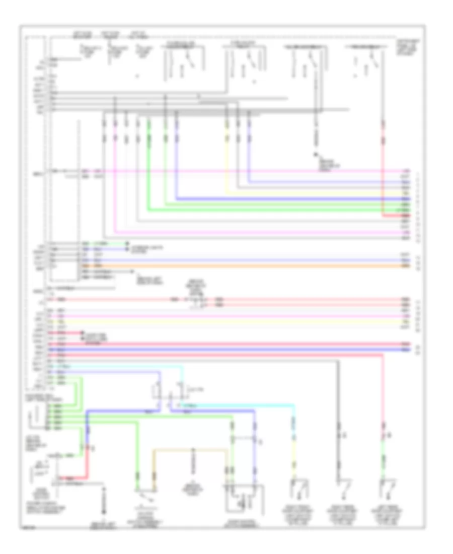
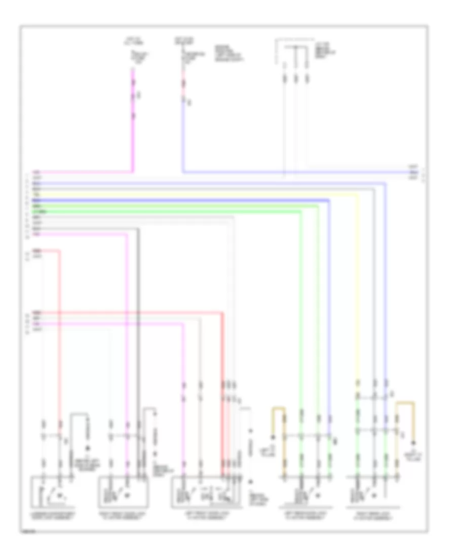
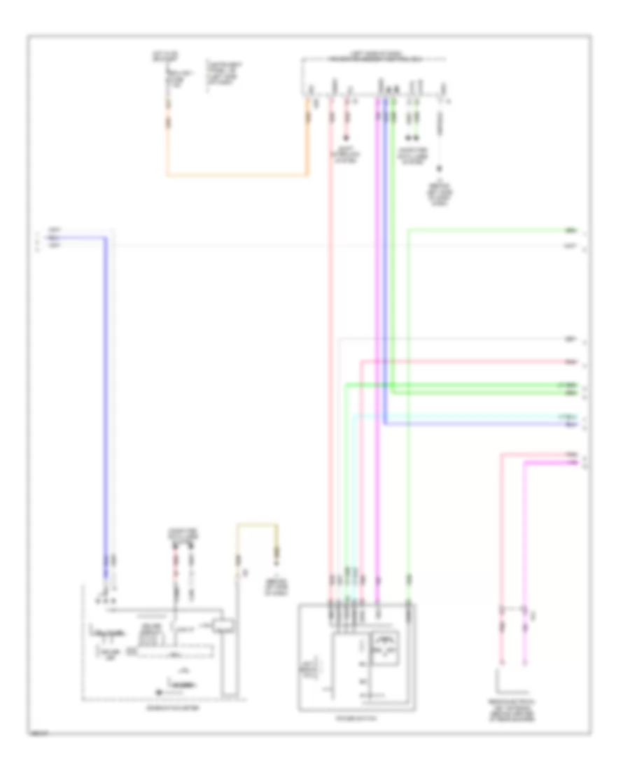
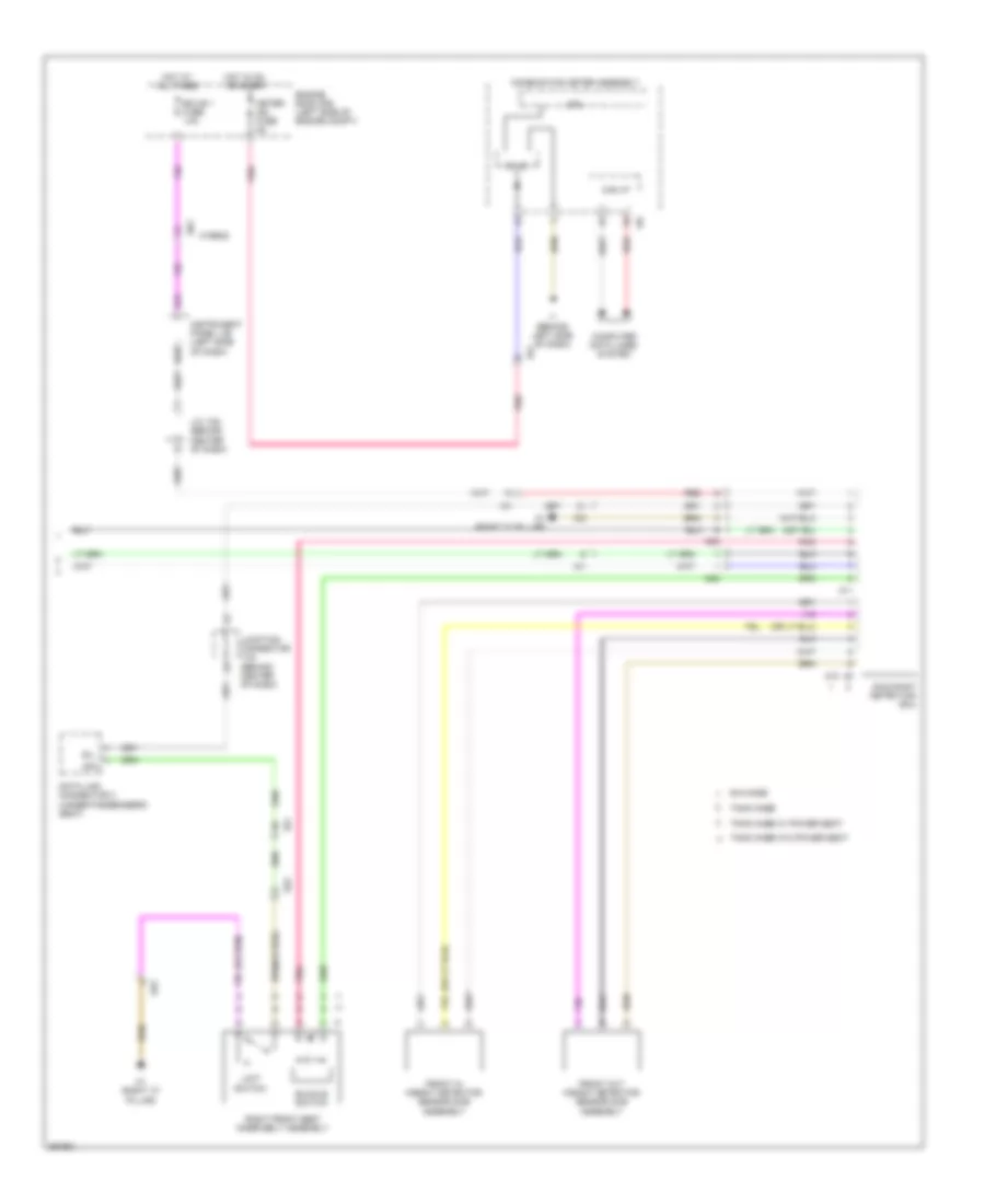
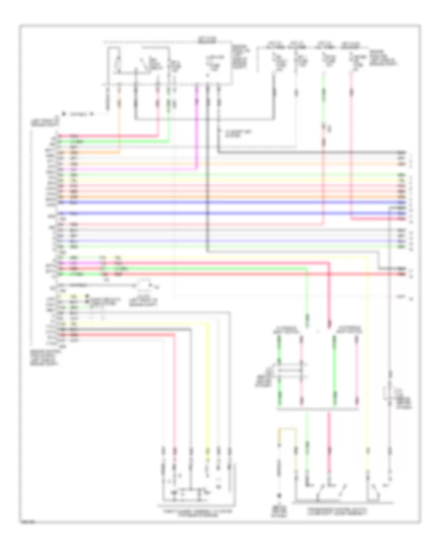
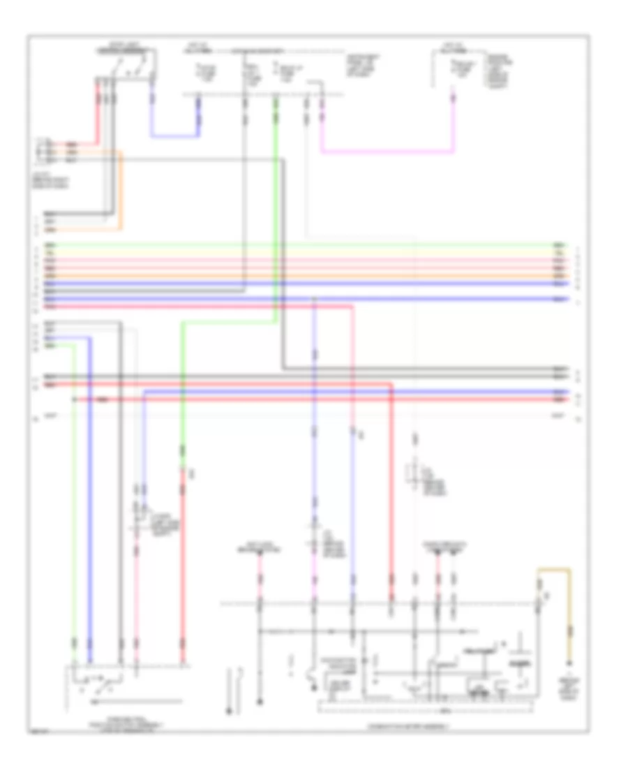
Automatic A/C Wiring Diagram, Except Hybrid (3 of 3) for Toyota Camry LE 2014
List of elements for Automatic A/C Wiring Diagram, Except Hybrid (3 of 3) for Toyota Camry LE 2014:
- (2.5l)
- (3.5l)
- +b1
- 2.5l
- 3.5l
- A/c control assembly (center of dash)
- A1 (left front of engine compt)
- A10
- A25
- Alt
- Alt fuse 120a
- Anti-theft system
- Canh
- Canl
- Cfan
- Computer data lines system
- Cooling fan ecu (3.5l) (front center of engine compt)
- Cooling fan motor
- Cooling fan motor (2.5l) (left front of engine compt)
- Cooling fan motor 2
- Cooling fan motor 2 (2.5l) (front center of engine compt)
- D36
- E26
- Ecu ig1 1 fuse 10a
- Engine control module (left side of engine compt)
- Engine coolant temperature sensor (2.5l: left rear of engine) (3.5l: top front of engine)
- Engine room j/b (left side of engine compt)
- Engine room r/b (2.5l) (left side of engine compt)
- Engine room r/b (3.5l) (left side of engine compt)
- Ethw
- Exterior lights
- F15
- F17
- Fan fuse 50a
- Fan relay
- Fan2
- Fanh
- Fanl
- Fn2s
- Gnd
- Gnd2
- Haz
- Heater switch, security indicator, rear window defogger switch, mirror
- Hot at all times
- Hot in on or start
- I3 (behind center of dash)
- Ia4
- Ig+
- Ign
- Ill+
- Ill-
- Instrument panel j/b (left side of dash)
- Integration relay
- Interior lights system
- J/c a73 (left front of engine compt)
- Lin 1
- Mcls
- Mgct
- P-ab
- Paon
- Passenger air bag on/off indicator hazard switch &
- Pnk
- Red
- Restraints system
- Rfan
- Rfc
- System
- Thw
- Z14
- Z15
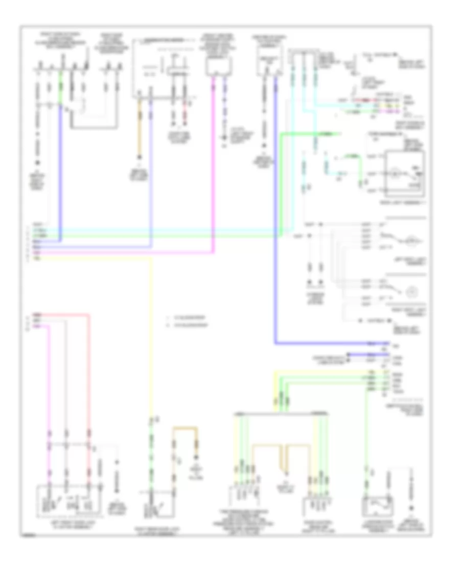
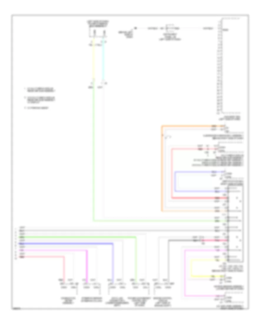
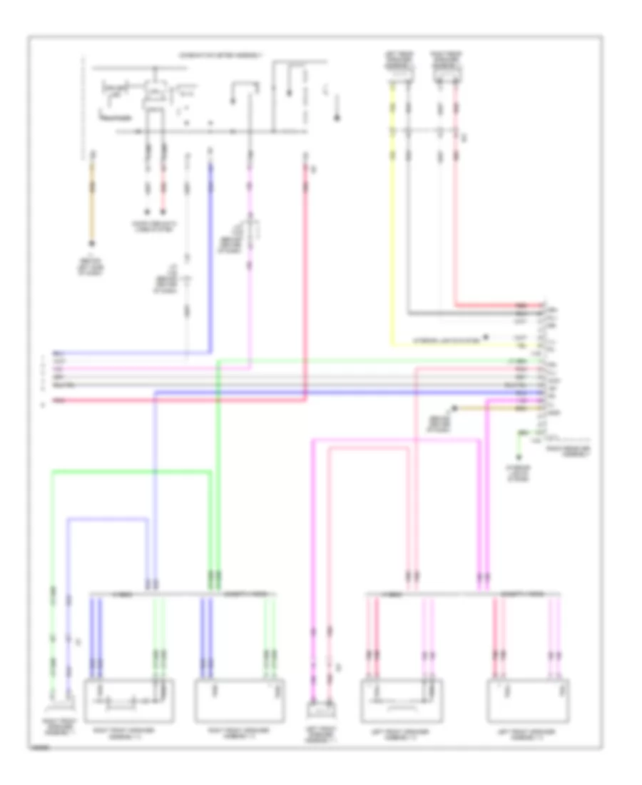
Automatic A/C Wiring Diagram, Hybrid (1 of 3) for Toyota Camry LE 2014
List of elements for Automatic A/C Wiring Diagram, Hybrid (1 of 3) for Toyota Camry LE 2014:
- (behind right side of dash) i5
- (front center of engine compt) ambient temperature sensor (thermistor assembly)
- (right front of engine compt) a/c pressure sensor (a/c tube & accessory assembly)
- (w/ seat heater) left seat heater switch
- A/c amplifier (right side of dash)
- A/c b fuse 7.5a
- A/c evaporator temperature sensor
- A/c unit (a/c harness assembly)
- B bus
- B21
- B27
- Blower motor (behind right side of dash)
- Blw
- Bus
- Bus g
- Canh
- Canl
- Computer data lines system
- Connector housing color (black)
- Connector housing color (green)
- Connector housing color (red)
- Damper servo motor (air inlet)
- Damper servo motor (air vent mode)
- Damper servo motor (left front side air mix)
- Damper servo motor (right front side air mix)
- Defogger system
- Eco switch
- Ecos
- Ecu
- Ecu ig1 2 fuse 10a
- Engine room r/b (left side of engine compt)
- Gnd
- Hot at all times
- Hot in on or start
- Htr fuse 50a
- Humidity sensor
- I3 (behind center of dash)
- I5 (behind right side of dash)
- I77
- Ia6
- Ia8
- Ia9
- Idh
- Ig+
- Ill+
- Ill-
- Instrument panel j/b (left side of dash)
- Interior lights system
- Is2
- Lin1
- Pnk
- Pre
- Ptc1
- Ptc2
- Rdfg
- Red
- S5-3
- S5-4
- S5v
- Seg3
- Sg-1
- Sg-2
- Sg-4
- Sga
- Shin
- Tam
- Tea
- Tfg
- Tng
- Tsd
- Tsp
Automatic A/C Wiring Diagram, Hybrid (2 of 3) for Toyota Camry LE 2014
List of elements for Automatic A/C Wiring Diagram, Hybrid (2 of 3) for Toyota Camry LE 2014:
- (right side of engine compt) engine room r/b 2
- A/c ig1 fuse 7.5a
- Automatic light control sensor (top center of dash)
- B22
- B39
- Cooler thermistor (room temperature sensor) (behind center of dash)
- D28
- D32
- Eng w/ pmp fuse 30a
- Engine room r/b (left side of engine compt)
- Hot at all times
- Hot in on or start
- Ia6
- Instrument panel j/b (left side of dash)
- Pnk
- Ptc htr 1 fuse 50a
- Ptc htr 2 fuse 50a
- Ptc htr relay 1
- Ptc htr relay 2
- Quick heater assembly (under center console)
- Red
- Solar sensor
- Tsl
- Tsr
Automatic A/C Wiring Diagram, Hybrid (3 of 3) for Toyota Camry LE 2014
List of elements for Automatic A/C Wiring Diagram, Hybrid (3 of 3) for Toyota Camry LE 2014:
- (left front of engine compt) a5
- (left front of engine) engine water pump
- +b1
- A/c control assembly (center of dash)
- A10
- A13
- A25
- A38
- A5 (left front of engine compt)
- Acpb
- Acpe
- Anti-theft system
- Ca1h
- Ca1l
- Canh
- Canl
- Clk
- Compressor w/ motor assembly
- Computer data lines system
- Cooling fan ecu (front center of engine compt)
- Cooling fan motor (left front of engine compt)
- Cooling fan motor 2 (front center of engine compt)
- D36
- Din
- Dout
- E28
- E3 (top rear of engine)
- E65
- Ea1
- Ea2
- Ecu ig1 1 fuse 10a
- Efi 3 fuse 7.5a
- Eng w/ pmp relay
- Engine control module (left side of engine compt)
- Engine coolant temperature sensor (left rear of engine)
- Engine room j/b (left side of engine compt)
- Engine room r/b (left side of engine compt)
- Ethw
- Eti
- Exterior lights
- Fan fuse 50a
- Fan relay
- Gnd
- Haz
- Heater switch, security indicator, rear window defogger switch, mirror
- Hot at all times
- Hot in on or start
- Hot w/ efi main relay energized
- I3 (behind center of dash)
- Idh
- Ig+
- Ig1
- Ill+
- Ill-
- Instrument panel j/b (left side of dash)
- Interior lights system
- Inverter w/ converter assembly (left front of engine compt)
- Ite
- Lin 1
- Nwp
- P-ab
- Paon
- Passenger air bag on/off indicator hazard switch &
- Pgnd
- Pnk
- Power management control ecu (left side of dash)
- Red
- Restraints system
- Rfc
- Stb
- Stbi
- Swp
- System
- Thw
- Wpi
- Wpo
- Z14
- Z15
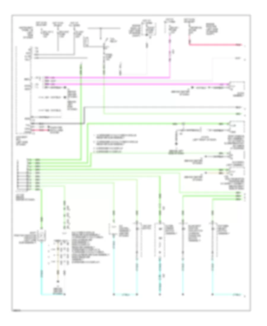
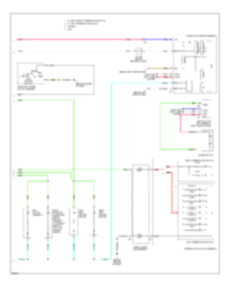
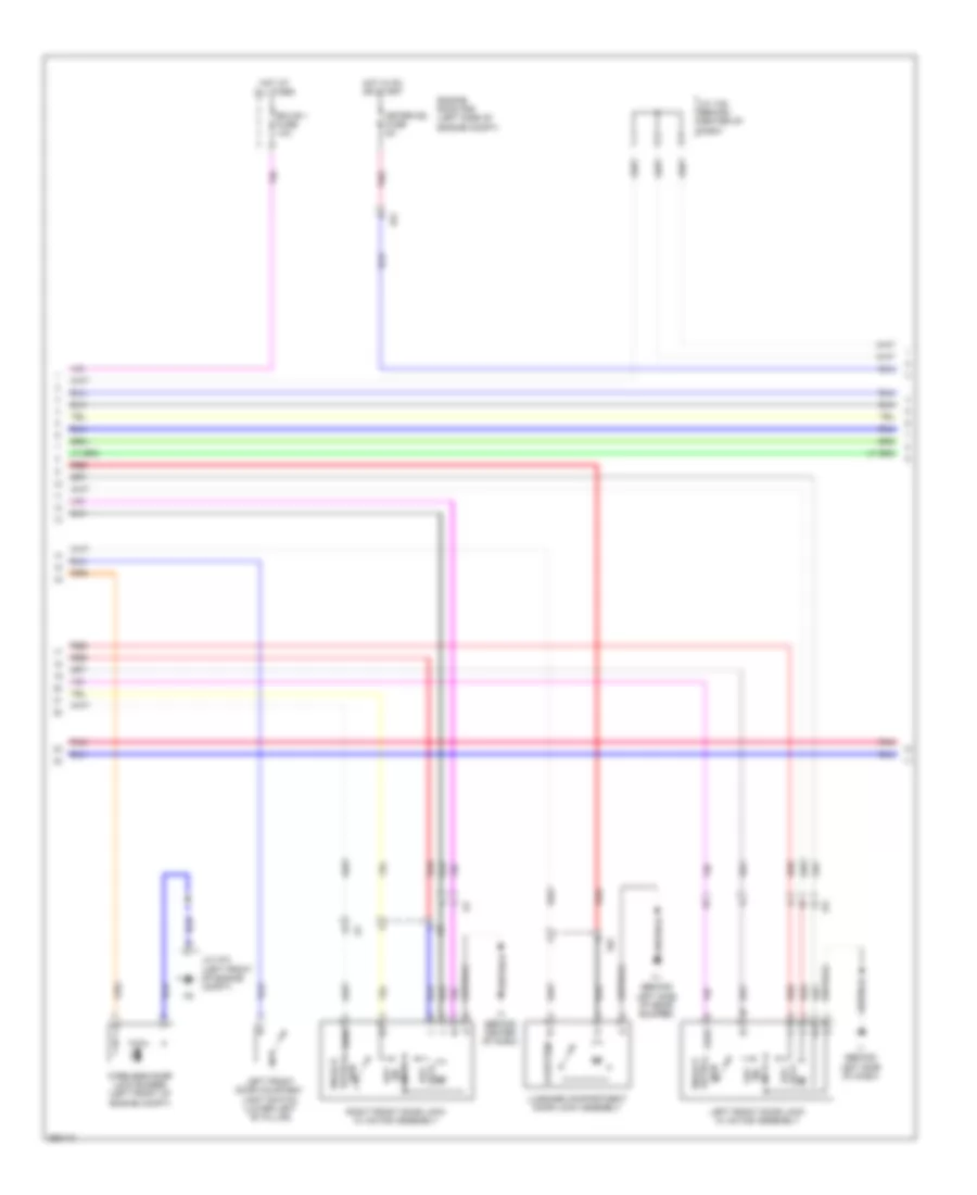
Manual A/C Wiring Diagram (1 of 3) for Toyota Camry LE 2014
List of elements for Manual A/C Wiring Diagram (1 of 3) for Toyota Camry LE 2014:
- (front center of engine compt) ambient temperature sensor (thermistor assembly)
- (right front of engine compt) a/c pressure sensor (a/c tube & accessory assembly)
- 3.5l
- A/c amplifier (right side of dash)
- A/c b fuse 7.5a
- A/c evaporator temperature sensor
- A/c ig1 fuse 7.5a
- A/c unit (a/c harness assembly)
- A70
- B bus
- B21
- B22
- B39
- Blw
- Bus
- Bus g
- Canh
- Canl
- Computer data lines system
- Connector housing color (black)
- Connector housing color (green)
- Connector housing color (red)
- Damper servo motor (air inlet)
- Damper servo motor (air vent mode)
- Damper servo motor (right front side air mix)
- Defogger system
- E76
- Floq
- Gnd
- Hot at all times
- Hot in on or start
- I5 (behind right side of dash)
- I77
- Ia8
- Ig+
- Instrument panel j/b (left side of dash)
- J/c a70 & e76 (left side of engine compt)
- Lin1
- Lock
- Mgc
- Pnk
- Pre
- Rdfg
- Red
- S5-1
- S5-3
- Sga
- Sig-2
- Sol+
- Tam
- Tea
- W/ smart key system
Manual A/C Wiring Diagram (2 of 3) for Toyota Camry LE 2014
List of elements for Manual A/C Wiring Diagram (2 of 3) for Toyota Camry LE 2014:
- 2.5l
- 3.5l
- Blower motor (behind right side of dash)
- Compressor assembly w/ pulley
- E1 (top rear of engine)
- E2 (top rear of engine)
- E73
- E74
- E75
- Ea2
- Engine room r/b (left side of engine compt)
- Gnd
- Hot at all times
- Htr fuse 50a
- I5 (behind right side of dash)
- Ia4
- Ia6
- Ia8
- Mg+
- Pnk
- Qufl
- Red
- S5fl
- Sgfl
- Sol+
- Sol-
- Ssr+
Manual A/C Wiring Diagram (3 of 3) for Toyota Camry LE 2014
List of elements for Manual A/C Wiring Diagram (3 of 3) for Toyota Camry LE 2014:
- (2.5l)
- (3.5l)
- +b1
- 2.5l
- 3.5l
- A/c control assembly (center of dash)
- A1 (left front of engine compt)
- A10
- A25
- Alt
- Alt fuse 120a
- Anti-theft system
- Canh
- Canl
- Cfan
- Computer data lines system
- Cooling fan ecu (3.5l) (front center of engine compt)
- Cooling fan motor
- Cooling fan motor (2.5l) (left front of engine compt)
- Cooling fan motor 2
- Cooling fan motor 2 (2.5l) (front center of engine compt)
- D36
- E26
- Ecu ig1 1 fuse 10a
- Engine control module (left side of engine compt)
- Engine coolant temperature sensor (2.5l: left rear of engine) (3.5l: top front of engine)
- Engine room j/b (left side of engine compt)
- Engine room r/b (2.5l) (left side of engine compt)
- Engine room r/b (3.5l) (left side of engine compt)
- Ethw
- Exterior lights
- F15
- F17
- Fan fuse 50a
- Fan relay
- Fan2
- Fanh
- Fanl
- Fn2s
- Gnd
- Gnd2
- Haz
- Heater switch, security indicatior, rear window defoger switch, mirror
- Hot at all times
- Hot in on or start
- I3 (behind center of dash)
- Ia4
- Ig+
- Ign
- Ill+
- Ill-
- Instrument panel j/b (left side of dash)
- Integration relay
- Interior lights system
- J/c a73 (left front of engine compt)
- Lin 1
- Mcls
- Mgct
- P-ab
- Paon
- Passenger air bag on/off indicator hazard switch &
- Pnk
- Red
- Restraints system
- Rfan
- Rfc
- System
- Thw
- Z14
- Z15
ANTI-LOCK BRAKES
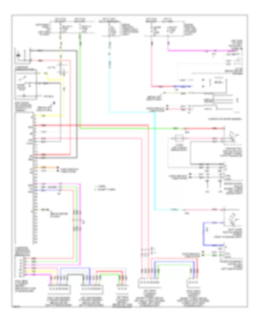
Anti-lock Brakes Wiring Diagram, Except Hybrid (1 of 2) for Toyota Camry LE 2014
List of elements for Anti-lock Brakes Wiring Diagram, Except Hybrid (1 of 2) for Toyota Camry LE 2014:
- (right front of engine compt) a3
- +bm
- +bs
- 5v ic
- A56
- Abs 1 fuse 50a
- Abs 2 fuse 30a
- Bat
- Brake actuator assembly (right front of engine compt)
- Brake fluid level warning switch (brake master cylinder reservoir sub-assembly) (on brake fluid reservoir)
- Can i/f
- Canh
- Canl
- Combination meter assembly
- Computer data lines system
- Cpu
- Cruise control system
- Csw
- D36
- Ecu-ig1 1 fuse 10a
- Engine room r/b (left side of engine compt)
- Ess
- Fl+
- Fl-
- Fr+
- Fr-
- Fsw+
- Gnd1
- Gnd2
- Hot at all times
- Hot in on or start
- I/f
- I1 (behind left side of dash)
- I18
- I3 (behind center of dash)
- Ia3
- Ig+
- Ig1
- Instrument panel j/b (left side of dash)
- Interior lights system
- J/c a73 (left front of engine compt)
- J/c i124 (behind center of dash)
- J/c i125 (behind center of dash)
- Led driver
- Meter ig2 fuse 5a
- Pnk
- Red
- Rl+
- Rl-
- Rr+
- Rr-
- Sp1
- Steering sensor (steering column)
- Stp
- Tell- tales
- Vsc off switch
Anti-lock Brakes Wiring Diagram, Except Hybrid (2 of 2) for Toyota Camry LE 2014
List of elements for Anti-lock Brakes Wiring Diagram, Except Hybrid (2 of 2) for Toyota Camry LE 2014:
- (left rear wheel hub assembly)
- (right rear wheel hub assembly)
- A1 (left front of engine compt)
- A51
- A52
- An1
- B26
- Becu
- Brake pedal load sensing switch (brake pedal support assembly) (on brake pedal support assembly)
- Canh
- Canl
- Computer data lines system
- D20
- D30
- D31
- Ecu-b 1 fuse 10a
- Engine room r/b (left side of engine compt)
- Gnd1
- Gnd2
- Hot at all times
- I1 (behind left side of dash)
- I12
- I13
- I3 (behind center of dash)
- Instrument panel j/b (left side of dash)
- J/c a71 (behind right side of dash)
- Left front speed sensor (left front wheel hub assembly)
- Left rear speed sensor
- Main body ecu (left side of dash)
- Oa1
- Parking brake switch assembly
- Pkb
- Pnk
- Red
- Right front speed sensor (right front wheel hub assembly)
- Right rear speed sensor
- Stop fuse 7.5a
- Stop light switch assembly
- Ho1
- In1
Anti-lock Brakes Wiring Diagram, Hybrid (1 of 2) for Toyota Camry LE 2014
List of elements for Anti-lock Brakes Wiring Diagram, Hybrid (1 of 2) for Toyota Camry LE 2014:
- (behind left side of dash) i1
- (lower left "b" pillar)
- 5v ic
- A3 (right front of engine compt)
- A46
- A47
- A5 (left front of engine compt)
- A56
- Aa1
- Abs 1 fuse 30a
- Abs 2 fuse 7.5a
- Abs mtr 1 fuse 50a
- Abs mtr 2 fuse 50a
- Bat
- Bm1
- Bm2
- Brake booster pump (right rear of engine compt)
- Buzzer
- C15
- Ca1h
- Ca1l
- Ca2h
- Ca2l
- Can i/f
- Canh
- Canl
- Combination meter assembly
- Computer data lines system
- Cpu
- Cruise control system
- Csw
- Cty
- D17
- D34
- D36
- Driver display
- Ecu ig2 2 fuse 7.5a
- Ecu-ig1 1 fuse 10a
- Engine room r/b (left side of engine compt)
- Ess
- Fl+
- Fl-
- Fr+
- Fr-
- Gnd
- Gnd1
- Gnd2
- Gnd3
- Gnd4
- Gnd5
- Gnd6
- Hot at all times
- Hot in on or start
- I/f
- I1 (behind left side of dash)
- I18
- I3 (behind center of dash)
- Ia3
- Ig+
- Ig1
- Ig2
- Instrument panel j/b (left side of dash)
- Interior lights system
- J/c i124 (behind center of dash)
- J/c i125 (behind center of dash)
- Lbl
- Led driver
- Left front door courtesy light switch
- Meter ig2 fuse 5a
- Mri1
- Mri2
- Mro1
- Mro2
- Pnk
- Red
- Rl+
- Rl-
- Rr+
- Rr-
- Skg
- Skid control ecu w/ actuator (brake booster w/ master cylinder assembly) (right side of engine compt)
- Sks
- Sks2
- Sp1
- Steering sensor (steering column)
- Stp
- Stp2
- Stpo
- Tell- tales
- Vcsk
- Vsc off switch
Anti-lock Brakes Wiring Diagram, Hybrid (2 of 2) for Toyota Camry LE 2014
List of elements for Anti-lock Brakes Wiring Diagram, Hybrid (2 of 2) for Toyota Camry LE 2014:
- (left front of engine compt) j/c a73
- (left rear wheel hub assembly)
- (right rear wheel hub assembly)
- A5 (left front of engine compt)
- A51
- A52
- Aa1
- An1
- B26
- Becu
- Brake fluid level warning switch (brake master cylinder reservoir assembly) (on brake fluid reservoir)
- Brake pedal stroke sensor assembly
- Canh
- Canl
- Computer data lines system
- D20
- D29
- D30
- D31
- Ecu-b 1 fuse 10a
- Engine room r/b (left side of engine compt)
- Engine room r/b 2 (right side of engine compt)
- Gnd1
- Gnd2
- Hot at all times
- I1 (behind left side of dash)
- I12
- I13
- I3 (behind center of dash)
- Instrument panel j/b (left side of dash)
- J/c a71 (left kick panel)
- J/c a73 (left front of engine compt)
- Left front speed sensor (left front wheel hub assembly)
- Left rear speed sensor
- Main body ecu (left side of dash)
- Nca
- Oa1
- Parking brake switch assembly
- Pkb
- Pnk
- Red
- Right front speed sensor (right front wheel hub assembly)
- Right rear speed sensor
- Skg
- Sks1
- Sks2
- Stop fuse 7.5a
- Stop light switch assembly
- Stop relay
- Vcsk
- Ho1
- In1
ANTI-THEFT
Forced Entry Wiring Diagram, Except Hybrid (1 of 2) for Toyota Camry LE 2014
List of elements for Forced Entry Wiring Diagram, Except Hybrid (1 of 2) for Toyota Camry LE 2014:
- (behind center of dash) j/c i126
- (center of dash) a/c control assembly
- (front center of engine compt) engine hood courtesy switch (hood lock assembly)
- (right side of dash) glass breakage microphone sensor
- (right side of dash) glass breakage sensor ecu assembly
- A23
- A51
- A52
- A53
- Acc
- Altb
- B26
- B27
- B28
- B35
- B38
- Becu
- Brx
- Btx
- C15
- C17
- Canh
- Canl
- Computer data lines system
- D/l-am1 fuse 20a
- D14
- D15
- D25
- D31
- Domr
- Door control switch
- Door control switch assembly
- Dumy
- Ecu-acc fuse 7.5a
- Ecu-ig1 2 fuse 10a
- Flcy
- Frcy
- Gbs
- Gbs sig
- Gnd
- Gnd1
- Gnd2
- Hcty
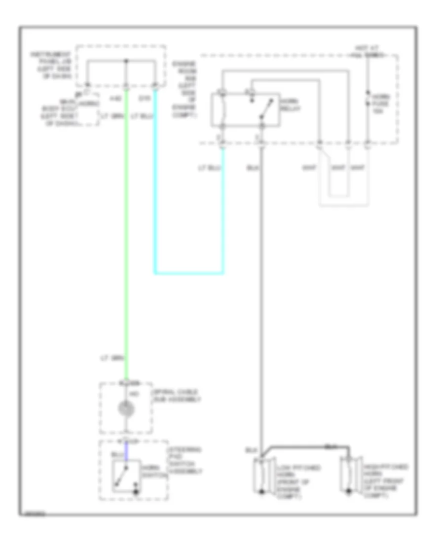
- Horn
- Horns system
- Hot at all times
- Hot in on or acc
- Hot in on or start
- I1 (behind left side of dash)
- I12
- I13
- I3 (behind center of dash)
- I5 (behind right side of dash)
- Ile
- In1
- Ind
- Instrument panel j/b (left side of dash)
- Io1
- Ik1
- J/c a73 (left front of engine compt)
- J/c i124 (behind center of dash)
- J/c i125 (behind center of dash)
- J/c i176
- Ji1
- Ji2
- Ki1
- Ksw
- Lcty
- Left front door courtesy light switch assembly (lower left "b" pillar)
- Left rear door courtesy light switch assembly (lower left "c" pillar)
- Lgcy
- Lock
- Lock key
- Lock un-
- Lsfl
- Lsfr
- Lsr
- Lssr
- Main body ecu (left side of dash)
- Mic+
- Mic-
- Nca
- Pnk
- Power window regulator master switch assembly
- Prg
- Rcty
- Rda
- Red
- Right front door courtesy light switch assembly (lower right "b" pillar)
- Right front door lock w/ motor assembly
- Right rear door courtesy light switch assembly (lower right "c" pillar)
- Security indicator
- Tion detec- unlock
- Ul1
- Ul2
- Ul3
- Un- key
- Un- lock
- Un-lock warning switch assembly (w/o smart key system)
- W/ smart key system
- W/o smart key system
Forced Entry Wiring Diagram, Except Hybrid (2 of 2) for Toyota Camry LE 2014
List of elements for Forced Entry Wiring Diagram, Except Hybrid (2 of 2) for Toyota Camry LE 2014:
- (behind left side of rear bumper) t1
- Brx
- Btx
- Canh
- Canl
- Certification ecu (w/ smart
- Check connector (remote engine
- Computer data lines system
- Courtesy
- Csel
- Cty
- Data
- Di143
- Dome fuse 7.5a
- Dome light
- Door control receiver (right "c" pillar)
- Ecu-b 1 fuse 10a
- Engine room r/b (left side of engine compt)
- Gnd
- Hot at all times
- I1 (behind left side of dash)
- I5 (behind right side of dash)
- I78
- Ia8
- Ignition key cylinder light (w/o smart key)
- Ill+
- Ill-
- Ind
- Io1
- Io2
- Is1
- Ic1
- J/c i128 (behind center of dash)
- Key system) (right side of dash)
- Ki1
- Left front door
- Left rear door lock w/ motor assembly
- Light cut relay (right side of dash)
- Lo1
- Lock
- Lock key
- Lock w/ motor assembly
- Lssr
- Luggage compartment door lock assembly
- Mn1
- N1 (left "c" pillar)
- O1 (right "c" pillar)
- O25
- Pnk
- Prg
- R+b
- Rco
- Rda
- Rdam
- Red
- Remote engine starter (if equipped) (behind center of dash)
- Resd
- Rgn1
- Right rear door lock w/ motor assembly
- Roof console box assembly
- Room light assembly 1
- Rsig
- Rslp
- S-horn fuse 7.5a
- S-horn relay
- Security horn assembly (right rear of engine compt)
- Slp
- Starter) i144
- Tion detec- unlock
- Tire pressure warning ecu & receiver (door control & tire pressure monitoring system receiver assembly) (w/ tire pressure warning system) (left "c" pillar)
- Tn1
- Transponder key amplifier (in steering column)
- Un- key
- W/ sliding roof
- W/ smart key system
- W/ tire pressure warning system
- W/o sliding roof
- W/o smart key system
- W/o tire pressure warning system
Forced Entry Wiring Diagram, Hybrid (1 of 2) for Toyota Camry LE 2014
List of elements for Forced Entry Wiring Diagram, Hybrid (1 of 2) for Toyota Camry LE 2014:
- (behind center of dash) i3
- A23
- A51
- A52
- A53
- Aa1
- Acc
- Altb
- An1
- B26
- B28
- B35
- Becu
- Bzr
- C15
- C17
- Canh
- Canl
- Computer data lines system
- Courtesy
- D/l-am1 fuse 20a
- D12
- D14
- D15
- D22
- D25
- D31
- Dome fuse 7.5a
- Domr
- Ecu-acc fuse 7.5a
- Ecu-b 1 fuse 10a
- Ecu-ig1 2 fuse 10a
- Engine room r/b (left side of engine compt)
- Exterior lights system
- Flcy
- Frcy
- Gbs
- Gnd1
- Gnd2
- Hcty
- Headlights system
- Horn
- Horn system
- Hot at all times
- Hot in on or acc
- Hot in on or start
- Hrly
- I1 (behind left side of dash)
- I12
- I13
- I3 (behind center of dash)
- Ia3
- Iab
- Ile
- In1
- Instrument panel j/b (left side of dash)
- Io1
- Ic1
- J/c a73 (left front of engine compt)
- J/c i125 (behind center of dash)
- J/c i160 (behind center of dash)
- Jl1
- Lcty
- Left front door courtesy light switch assembly (lower left "b" pillar)
- Left rear door courtesy light switch assembly (lower left "c" pillar)
- Left rear door lock
- Lgcy
- Light cut relay (right side of dash)
- Lsfl
- Lsfr
- Lsr
- Lssr
- Luggage compartment door lock assembly
- Main body ecu (left side of dash)
- Meter-ig2 fuse 5a
- Mn1
- N1 (left "c" pillar)
- Pnk
- Rcty
- Red
- Right front door courtesy light switch assembly (lower right "b" pillar)
- Right front door lock w/ motor assembly
- Right rear door courtesy light switch assembly (lower right "c" pillar)
- S-horn fuse 7.5a
- S-horn relay
- Security horn (right rear of engine compt)
- T1 (behind left side of rear bumper)
- Tion detec- unlock
- Tn1
- To1
- Trly
- Ul3
- W/ motor assembly
- Wireless door lock buzzer (left front of engine compt)
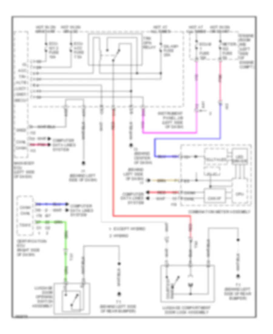
Forced Entry Wiring Diagram, Hybrid (2 of 2) for Toyota Camry LE 2014
List of elements for Forced Entry Wiring Diagram, Hybrid (2 of 2) for Toyota Camry LE 2014:
- (behind left side of dash)
- (center of dash) a/c control assembly
- (front center of engine compt) engine hood courtesy switch (hood lock assembly)
- (right side of dash) (if equipped) glass breakage microphone
- (right side of dash) (if equipped) glass breakage sensor ecu assembly
- 5v 1c
- Can i/f
- Canada
- Canh
- Canl
- Certification ecu (right side of dash)
- Combination meter
- Computer data lines system
- Cpu
- Csel
- Cty
- Data
- Door
- Door control receiver (right "c" pillar)
- Gbs sig
- Gnd
- I1 (behind left side of dash)
- I18
- I3 (behind center of dash)
- I5 (behind right side of dash)
- I86
- I87
- Ig+
- Ind
- Interior lights system
- Io2
- Is1
- Ik1
- J/c a73 (left front of engine compt)
- J/c i128 (behind center of dash)
- J/c s18 (left front of roof)
- Ki1
- Left front door lock w/ motor assembly
- Left spot light assembly
- Lo1
- Lock
- Lock key
- Lssr
- Luggage door opening switch assembly
- Mic+
- Mic-
- Nca
- O1 (right "c" pillar)
- O33
- Off
- Rco
- Rdam
- Red
- Right rear door lock
- Right spot light assembly
- Roof console box assembly
- Room light assembly 1
- Rrmp
- Security ind
- T1 (behind left side of rear bumper)
- Tion detec- unlock
- Tire pressure warning ecu & receiver (door control & tire pressure monitoring system receiver assembly) (left "c" pillar)
- To1
- Tsw5
- Un- key
- Usa
- W/ motor assembly
- W/ sliding roof
- W/o sliding roof
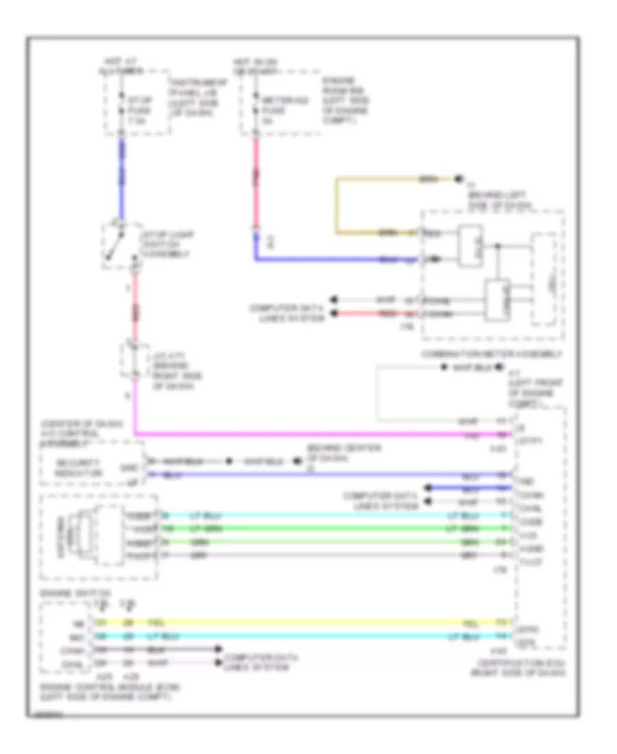
Immobilizer Wiring Diagram, Except Hybrid with Smart Key System for Toyota Camry LE 2014
List of elements for Immobilizer Wiring Diagram, Except Hybrid with Smart Key System for Toyota Camry LE 2014:
- (behind center of dash) i3
- (center of dash) a/c control assembly
- 2.5l
- 3.5l
- 5v ic
- A1 (left front of engine compt)
- A25
- A43
- Agnd
- Can i/f
- Canh
- Canl
- Certification ecu (right side of dash)
- Code
- Coil antenna
- Combination meter assembly
- Computer data lines system
- Cpu
- D30
- Efii
- Efio
- Engine control module (ecm) (left side of engine compt)
- Engine room r/b (left side of engine compt)
- Engine switch
- Gnd
- Hot at all times
- Hot in on or start
- I1 (behind left side of dash)
- I18
- I78
- Ia3
- Ig+
- Imi
- Imo
- Ind
- Instrument panel j/b (left side of dash)
- J/c a71 (behind right side of dash)
- Meter-ig2 fuse 5a
- Pnk
- Red
- Security indicator
- Stop fuse 7.5a
- Stop light switch assembly
- Stp1
- Txct
- Vc5
Immobilizer Wiring Diagram, Except Hybrid without Smart Key System for Toyota Camry LE 2014
List of elements for Immobilizer Wiring Diagram, Except Hybrid without Smart Key System for Toyota Camry LE 2014:
- (behind center of dash) j/c i124
- (behind center of dash) j/c i126
- A/c control assembly (center of dash)
- A25
- A49
- Agnd
- Ant1
- Ant2
- B26
- Code
- Computer data lines system
- D31
- Ecu-b 1 fuse 10a
- Ecu-ig2 2 fuse 7.5a
- Efii
- Efio
- Engine control module (ecm) (left side of engine compt)
- Engine room r/b (left side of engine compt)
- Gnd
- Hot at all times
- Hot in on or start
- I1 (behind left side of dash)
- I3 (behind center of dash)
- Ia3
- Ignition key cylinder light ind
- Ill+
- Ill-
- Imi
- Imo
- Ind
- Instrument panel j/b (left side of dash)
- Interior lights system
- J/c i125 (behind center of dash)
- Ksw
- Red
- Security indicator
- Transponder key amplifier (in steering column)
- Transponder key coil
- Transponder key ecu assembly (behind left center of dash)
- Txct
- Unlock warning switch
- Vc5
- W/ theft deterrent system
- W/o theft deterrent system
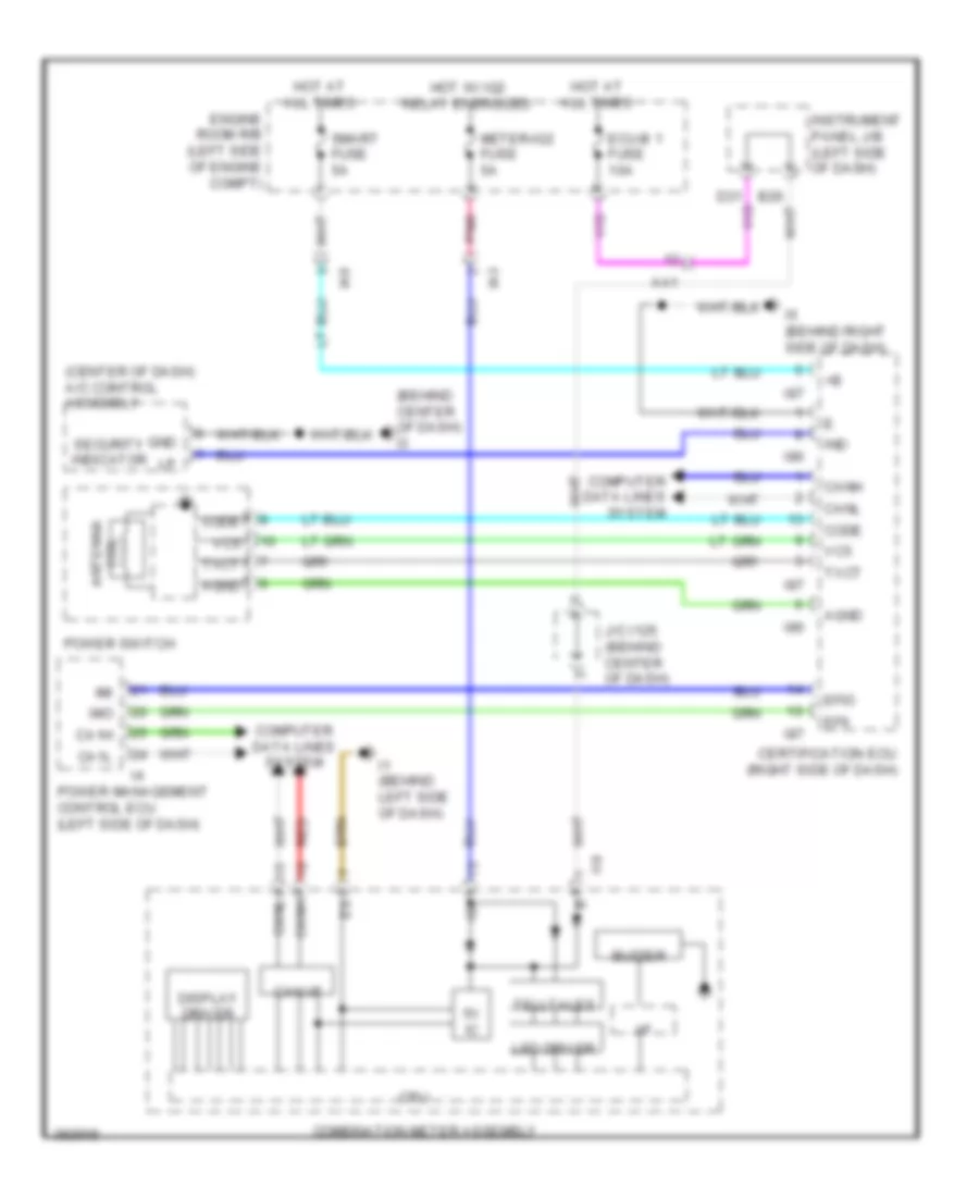
Immobilizer Wiring Diagram, Hybrid for Toyota Camry LE 2014
List of elements for Immobilizer Wiring Diagram, Hybrid for Toyota Camry LE 2014:
- (behind center of dash) i3
- (center of dash) a/c control assembly
- 5v ic
- Aa1
- Agnd
- Buzzer
- Ca1h
- Ca1l
- Can i/f
- Canh
- Canl
- Certification ecu (right side of dash)
- Code
- Coil antenna
- Combination meter assembly
- Computer data lines system
- Cpu
- Display driver
- Ecu-b 1 fuse 10a
- Efii
- Efio
- Engine room r/b (left side of engine compt)
- Gnd
- Hot at all times
- Hot w/ ig2 relay energized
- I/f
- I1 (behind left side of dash)
- I18
- I5 (behind right side of dash)
- I86
- I87
- Ia3
- Ia8
- Ig+
- Imi
- Imo
- Ind
- Instrument panel j/b (left side of dash)
- J/c i125 (behind center of dash)
- Led driver
- Meter-ig2 fuse 5a
- Pnk
- Power management control ecu (left side of dash)
- Power switch
- Red
- Security indicator
- Smart fuse 5a
- Telltales
- Txct
- Vc5
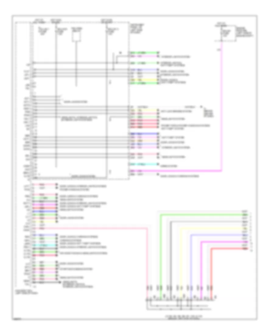
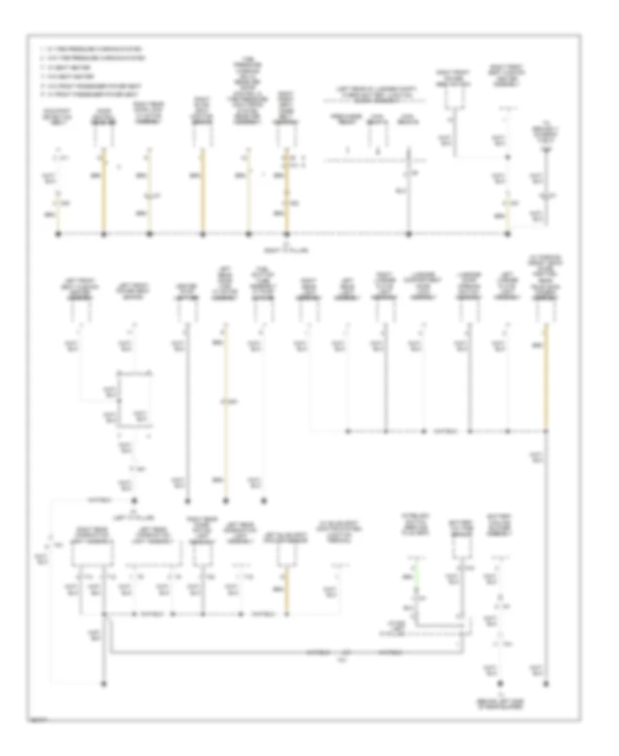
BODY CONTROL MODULES
2.5L
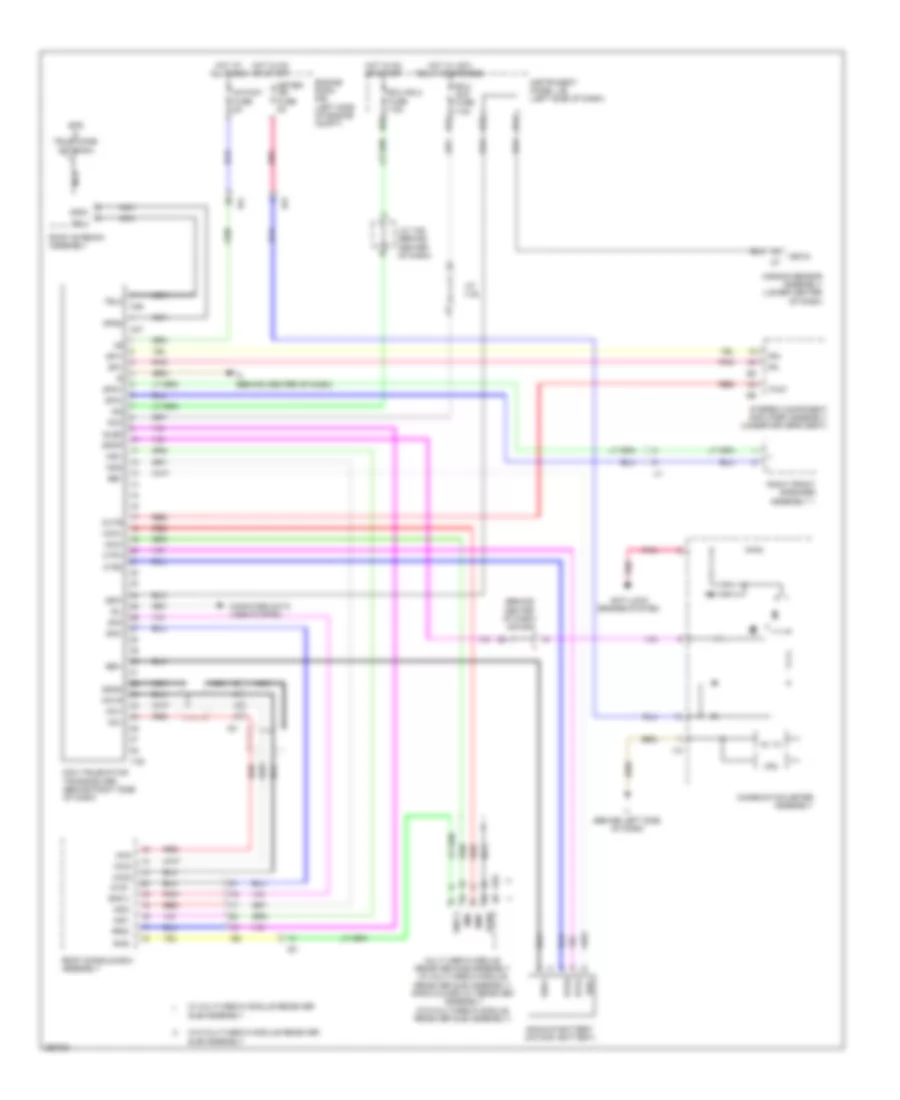
2.5L, Body ECU Wiring Diagram, Except Hybrid (1 of 2) for Toyota Camry LE 2014
List of elements for 2.5L, Body ECU Wiring Diagram, Except Hybrid (1 of 2) for Toyota Camry LE 2014:
- A23
- A53
- Acan
- Acc
- Act+
- Act-
- Actd
- Air conditioning & headlights systems
- Altb
- Anti-lock brakes system
- Anti-theft system
- B13
- B26
- B28
- B30
- B34
- B35
- B38
- Becu
- Brx
- Btx
- Bzr
- C15
- C17
- Canh
- Canl
- Cltb
- Clte
- Clts
- D/l-am 1 fuse 20a
- D11
- D12
- D14
- D15
- D20
- D22
- D23
- D25
- D31
- D38
- D39
- Dim
- Domr
- Door locks & anti theft systems
- Door locks & anti-theft systems
- Door locks & interior lights systems
- Door locks & warning systems
- Door locks system
- Drl
- Ecu-acc fuse 7.5a
- Ecu-b1 fuse 10a
- Ecu-ig1 2 fuse 10a
- Engine room r/b (left side of engine compt)
- Ffgo
- Ffog
- Flcy
- Frcy
- Gbs
- Gnd1
- Hcty
- Head
- Headlights system
- Headlights, exterior lights & interior lights systems
- Headlights, interior lights & exterior lights systems
- Horn
- Horns system
- Hot at all times
- Hot in on or acc
- Hot in on or start
- Hrly
- I100
- I103
- I13
- I3 (behind center of dash)
- I93
- I94
- I95
- I96
- I97
- Ile
- Instrument panel j/b (left side of dash)
- Interior lights & anti-theft systems
- Interior lights system
- J/c i93, i94, i95, i96, i97, i100, & i103 (behind left side of dash)
- Ksw
- Lcty
- Lgcy
- Lgyl
- Lin2
- Lsfl
- Lsfr
- Lsr
- Main body ecu (left side of dash)
- Pkb
- Pnk
- Power tops & power windows systems
- Power windows system
- Prg
- Pws
- Rcty
- Rda
- Red
- Starting/charging system
- Tail
- Tr+
- Trk open relay
- Trly
- Ul1
- Ul2
- Ul3
- Warning systems
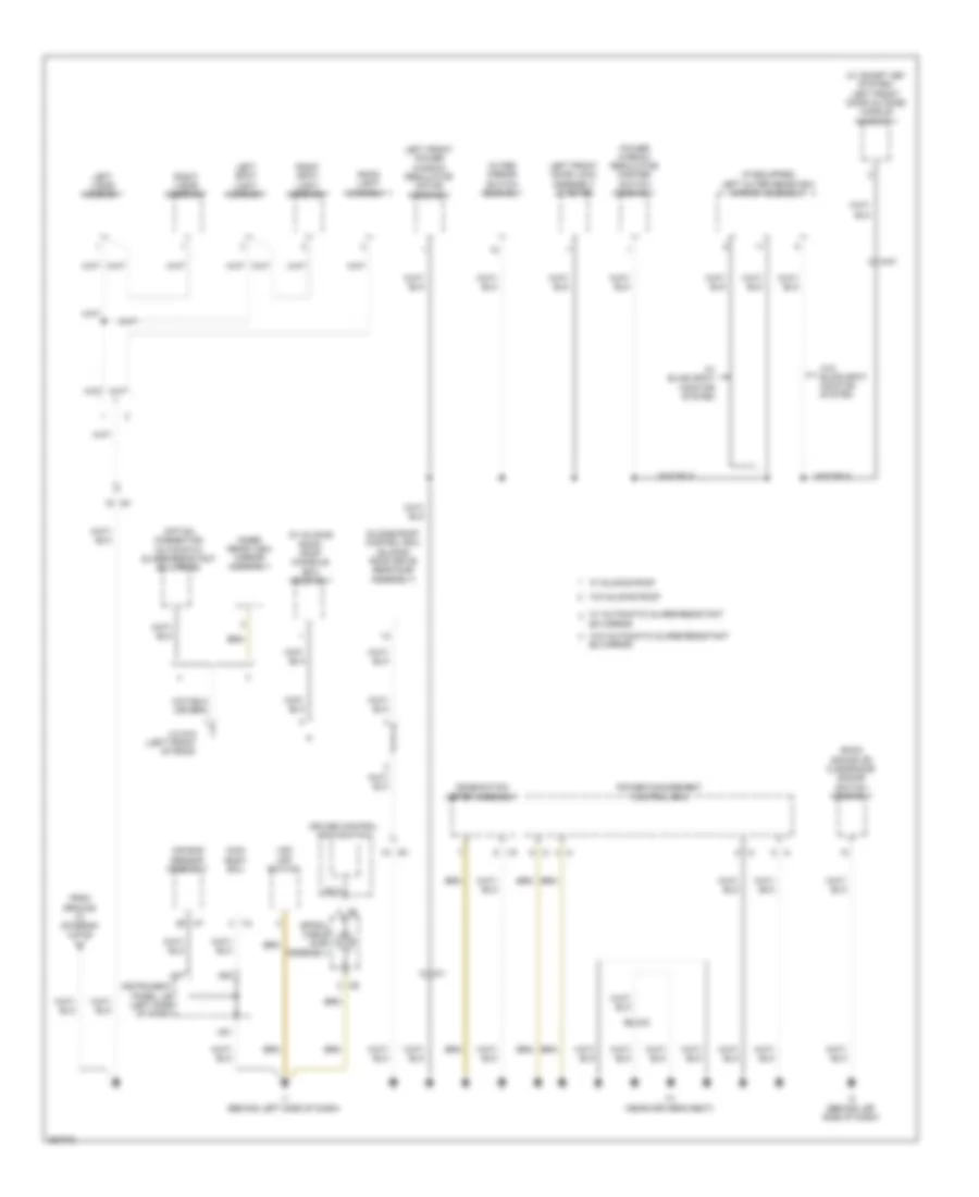
2.5L, Body ECU Wiring Diagram, Except Hybrid (2 of 2) for Toyota Camry LE 2014
List of elements for 2.5L, Body ECU Wiring Diagram, Except Hybrid (2 of 2) for Toyota Camry LE 2014:
- (behind right side of dash)
- (left side of dash) power steering ecu assembly
- 2.5l
- 3.5l
- A/c amplifier assembly (right side of dash)
- A25
- A51
- A52
- Air bag sensor assembly (lower center of dash)
- Anti-theft system
- Brake actuator assembly (right front of engine compt)
- Canh
- Canl
- Certification ecu (right side of dash)
- Clearance warning ecu assembly (behind right side of dash)
- Combination meter assembly
- Data link connector 3 (under passenger's seat)
- Dumy
- Engine control module (left side of engine compt)
- Gnd2
- I1 (behind left side of dash)
- I111
- I12
- I155
- I18
- I67
- I77
- I78
- Ia8
- Ii01
- Ii02
- Ii04
- Ii05
- Ii06
- Ii07
- Ii08
- Ind
- Instrument panel j/b (left side of dash)
- Ij2
- J/c i101,i102, i104, i105 i106, i107, i108 & i111 (behind right side of dash)
- Main body ecu (left side of dash)
- Multi-media receiver sub-assembly module (w/ multi-media module receiver assembly) radio & display receiver assembly (w/o multi-media module receiver assembly)
- Network gateway ecu
- Pnk
- Red
- Steering sensor (steering column)
- W/ multi-media module receiver sub-assembly
- W/o multi-media module receiver sub-assembly w/ display 10 & 6 speaker
- W/o smart key system
- Yaw rate sensor
2.5L, Body ECU Wiring Diagram, Hybrid (1 of 2) for Toyota Camry LE 2014
List of elements for 2.5L, Body ECU Wiring Diagram, Hybrid (1 of 2) for Toyota Camry LE 2014:
- A23
- A53
- Aa1
- Acan
- Acc
- Act+
- Act-
- Actd
- Air conditioning & headlights systems
- Altb
- Anti-lock brakes & headlights systems
- Anti-theft system
- B13
- B26
- B28
- B30
- B35
- B38
- Becu
- Bzr
- C15
- C17
- Ca1h
- Ca1l
- Canh
- Canl
- Cltb
- Clte
- Clts
- D/l-am 1 fuse 20a
- D11
- D12
- D14
- D15
- D20
- D22
- D23
- D25
- D31
- D38
- D39
- Dim
- Domr
- Door locks & anti-theft systems
- Door locks & interior lights systems
- Door locks & warning systems
- Door locks system
- Drl
- Ecu-acc fuse 7.5a
- Ecu-b1 fuse 10a
- Ecu-ig1 2 fuse 10a
- Engine room r/b (left side of engine compt)
- Ffgo
- Ffog
- Flcy
- Frcy
- Gbs
- Gnd1
- Hcty
- Head
- Headlights system
- Headlights, exterior lights & interior lights systems
- Headlights, interior lights & exterior lights system
- Horn
- Horns system
- Hot at all times
- Hot in on or acc
- Hot in on or start
- Hrly
- I109
- I110
- I13
- I3 (behind center of dash)
- I93
- I94
- I95
- I96
- I97
- Ia4
- Ile
- Instrument panel j/b (left side of dash)
- Interior lights & anti-theft systems
- Interior lights system
- J/c i93, i94, i95, i96, i97, i109 & i110 (behind left side of dash)
- Lcty
- Lgcy
- Lgyl
- Lin2
- Lsfl
- Lsfr
- Lsr
- Main body ecu (left side of dash)
- Navigation system
- Pkb
- Pnk
- Power tops & power windows systems
- Power windows system
- Prg
- Pws
- Rcty
- Rda
- Red
- Sftp
- Skid control ecu w/ actuator (brake booster w/ master cylinder assembly) (right side of engine compt)
- Tail
- Tr+
- Trk open relay
- Trly
- Ul1
- Ul3
2.5L, Body ECU Wiring Diagram, Hybrid (2 of 2) for Toyota Camry LE 2014
List of elements for 2.5L, Body ECU Wiring Diagram, Hybrid (2 of 2) for Toyota Camry LE 2014:
- (left side of dash) power steering ecu assembly
- A/c amplifier assembly (right side of dash)
- A25
- A51
- A52
- Air bag sensor assembly (lower center of dash)
- Caih
- Cail
- Canh
- Canl
- Certification ecu (right side of dash)
- Clearance warning ecu assembly (behind right side of dash)
- Combination meter assembly
- Data link connector 3 (under passenger's seat)
- Engine control module (left side of engine compt)
- Gnd2
- I1 (behind left side of dash)
- I111
- I12
- I155
- I18
- I47
- I67
- I77
- I87
- Ia8
- Ii00
- Ii01
- Ii02
- Ii03
- Ii04
- Ii06
- Ii07
- Instrument panel j/b (left side of dash)
- Ij2
- J/c i101, i102, i103, i104, i106, i107, i100 & i111 (behind right side of dash)
- Main body ecu (left side of dash)
- Multi-media module receiver sub-assembly (w/ multi-media module receiver assembly) radio & display receiver assembly (w/o multi-media module receiver assembly)
- Pnk
- Power management control ecu (left side of dash)
- Red
- Steering sensor (steering column)
- W/ multi-media module receiver sub-assembly
- W/ parking assist
- W/o multi-media module receiver sub-assembly w/ display
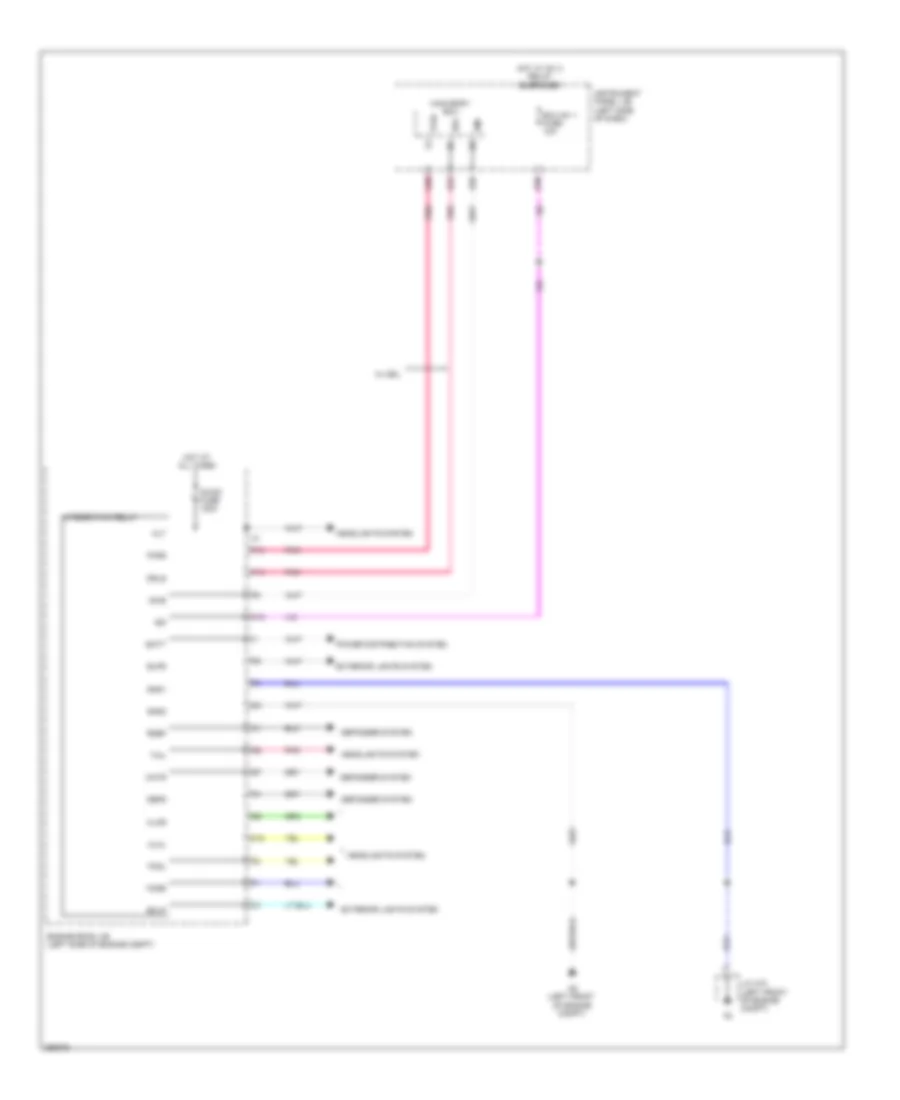
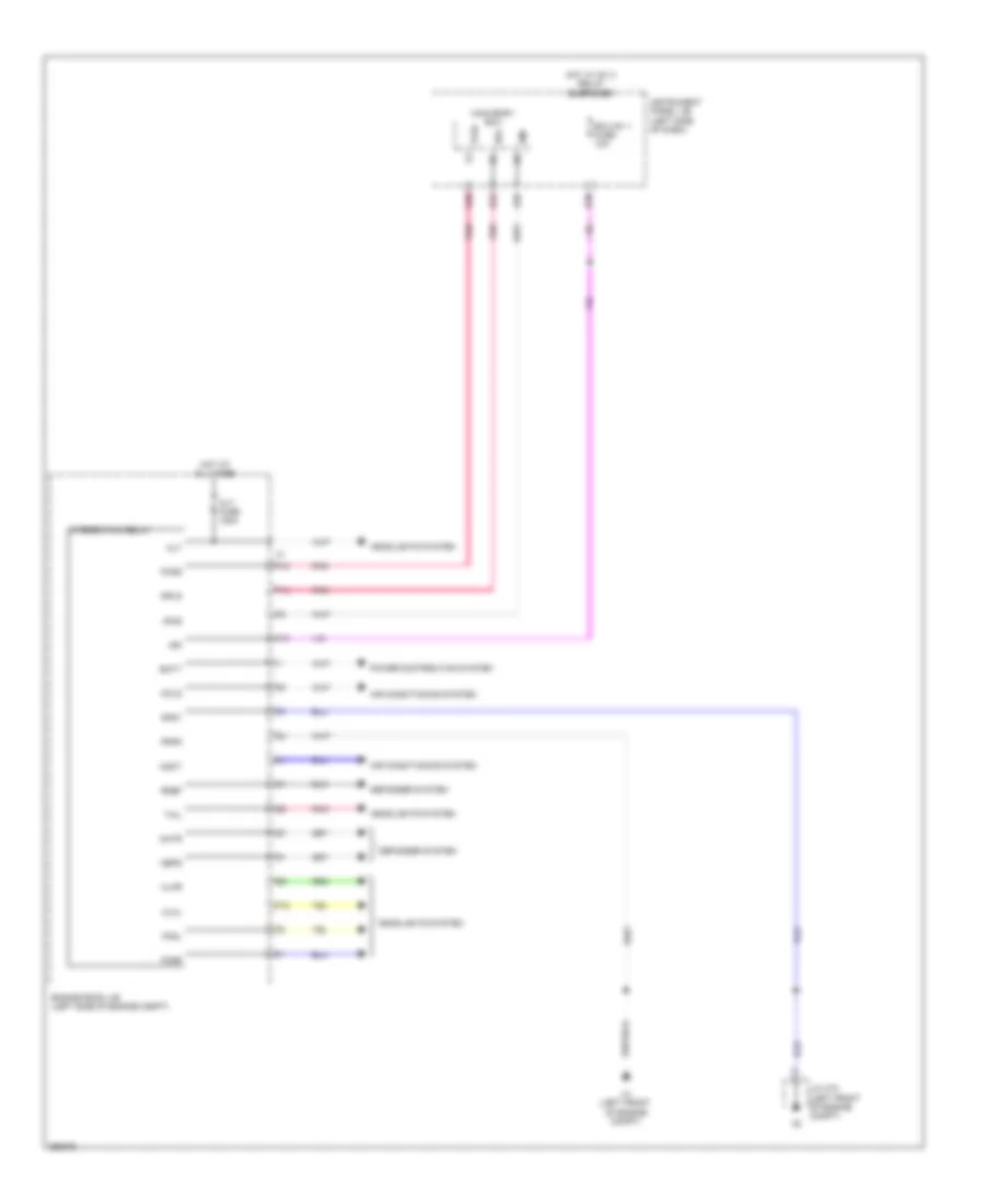
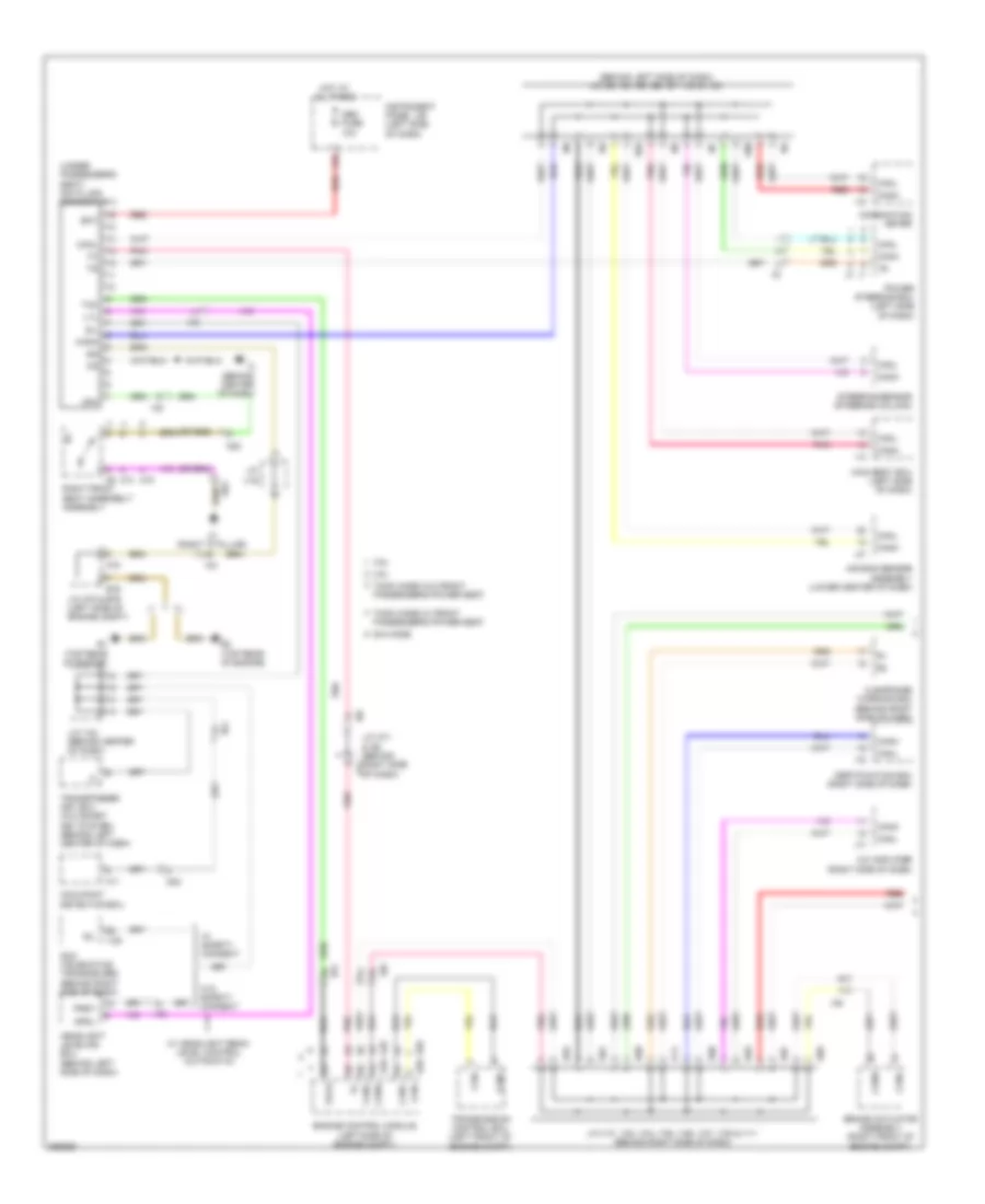
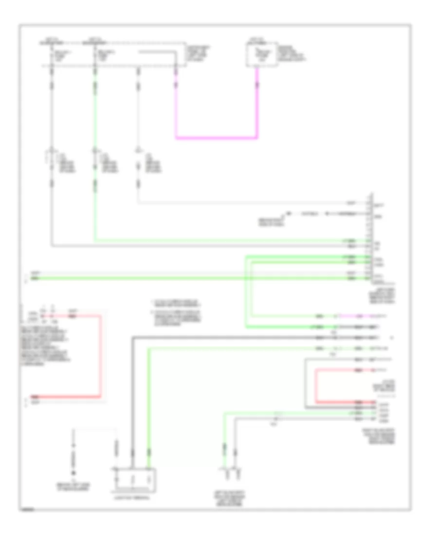
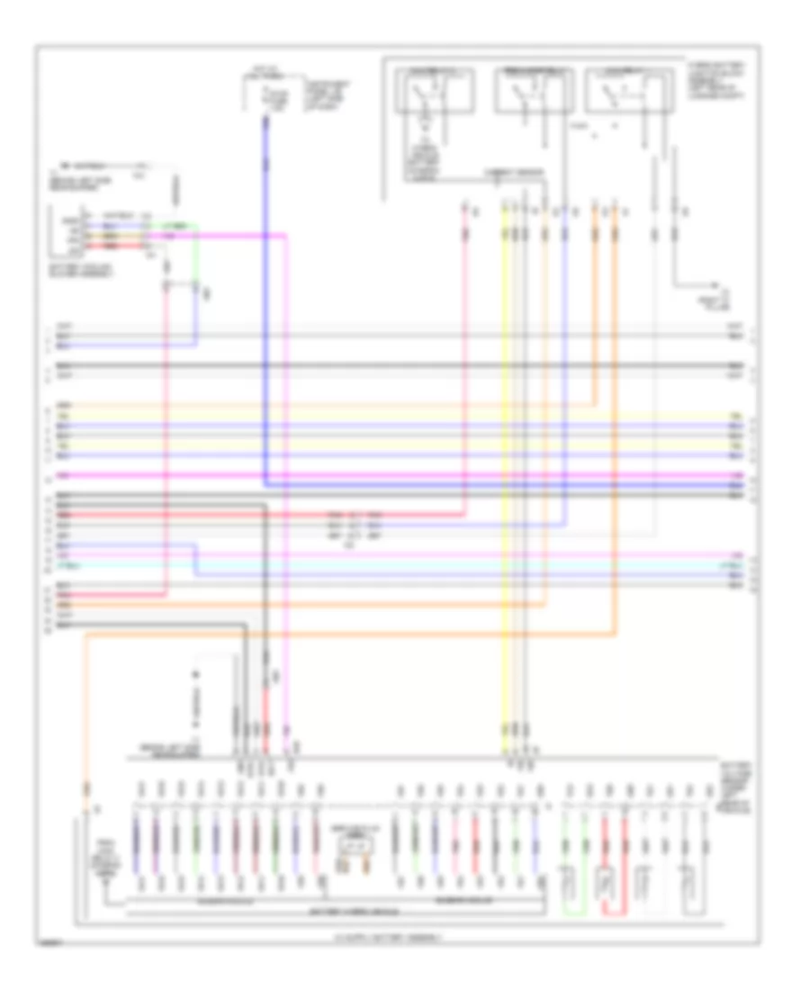
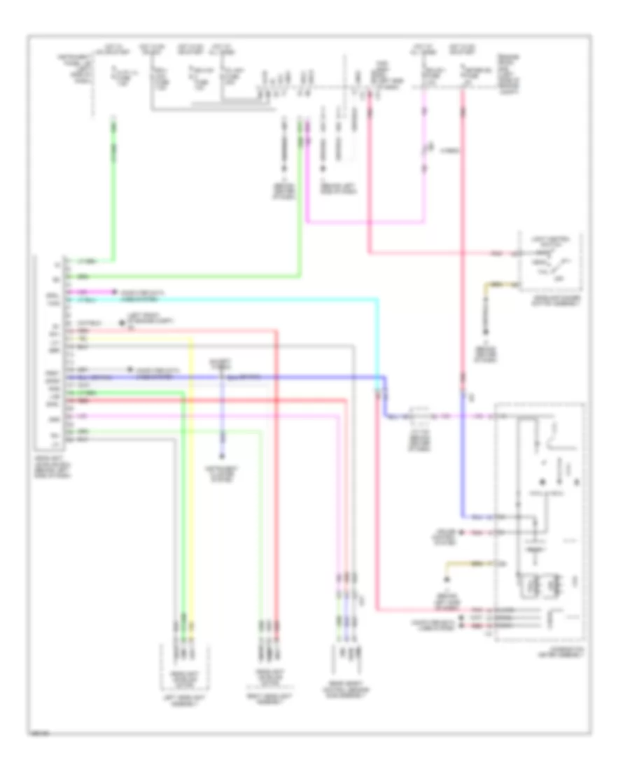
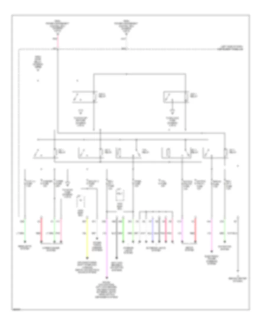
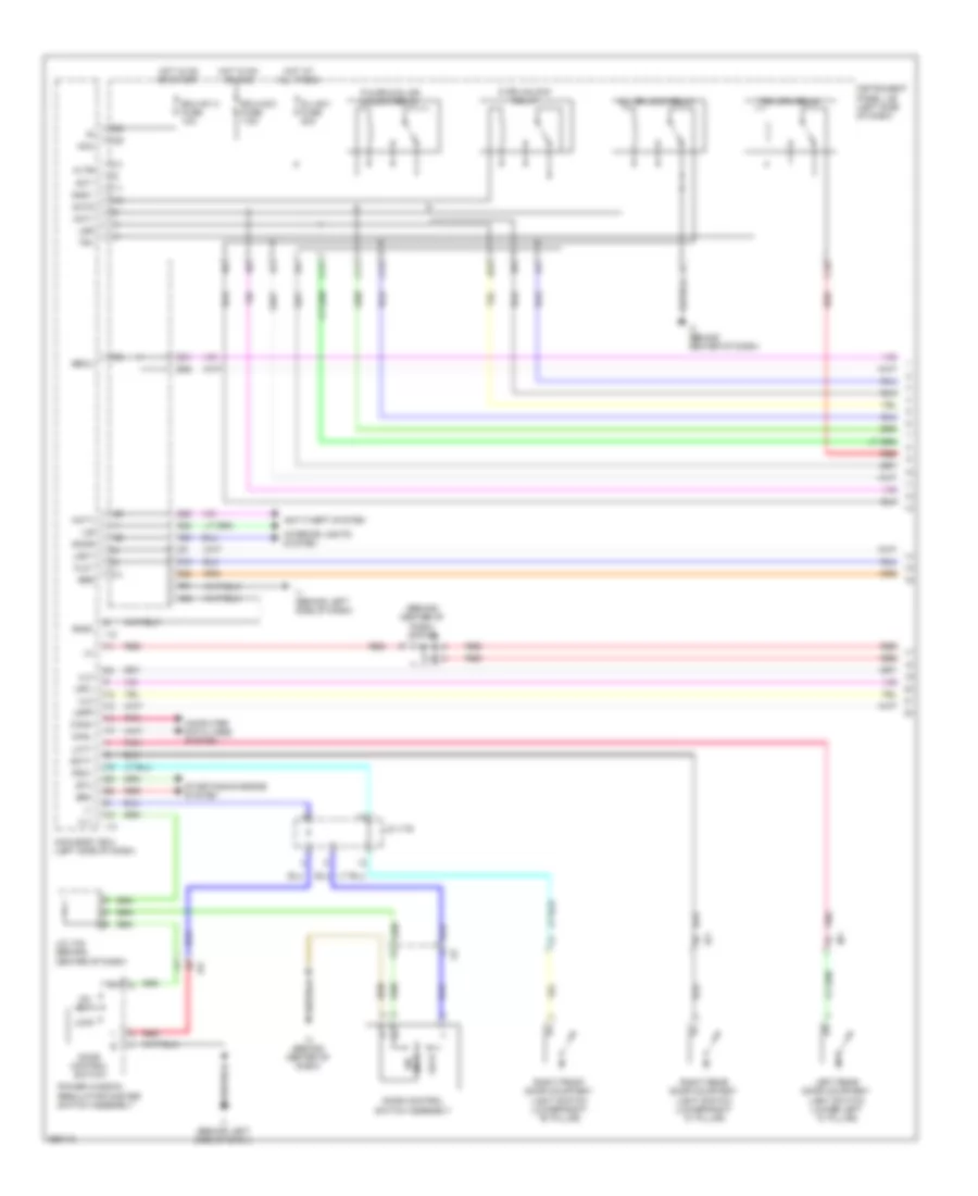
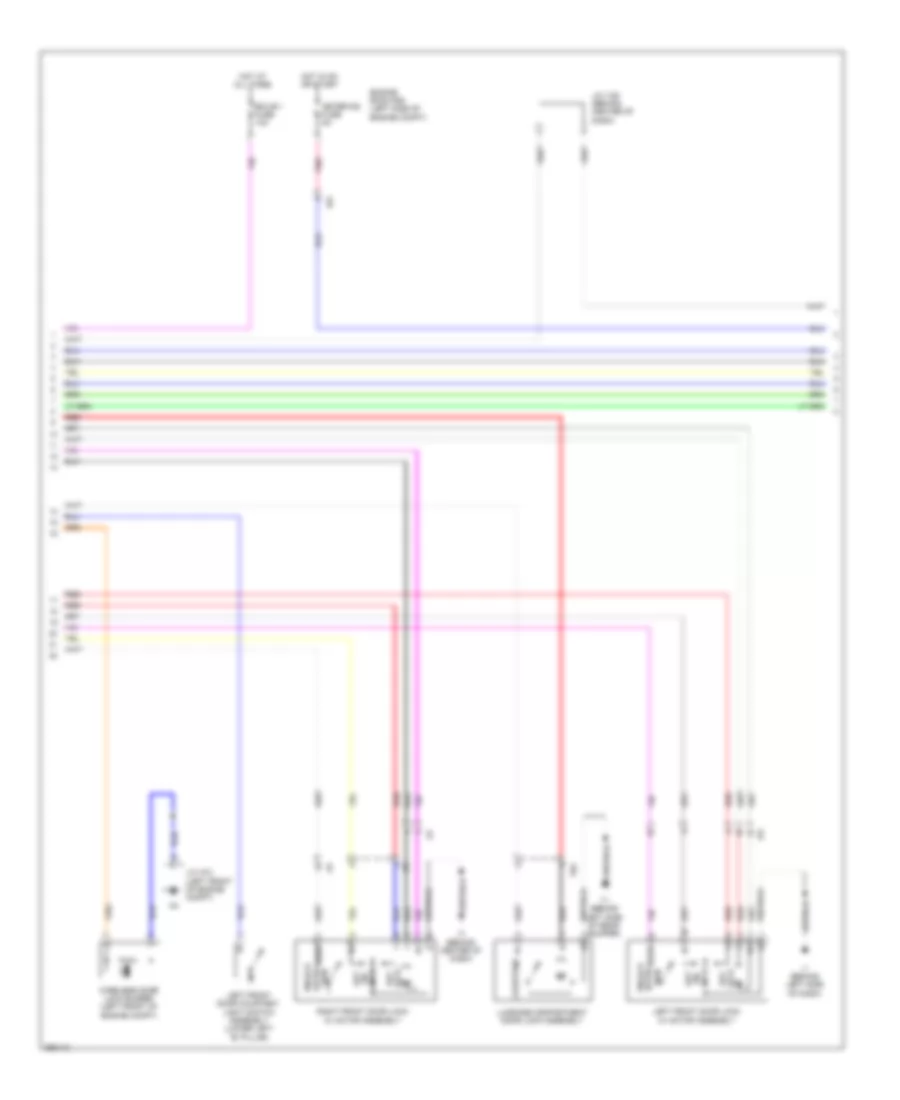
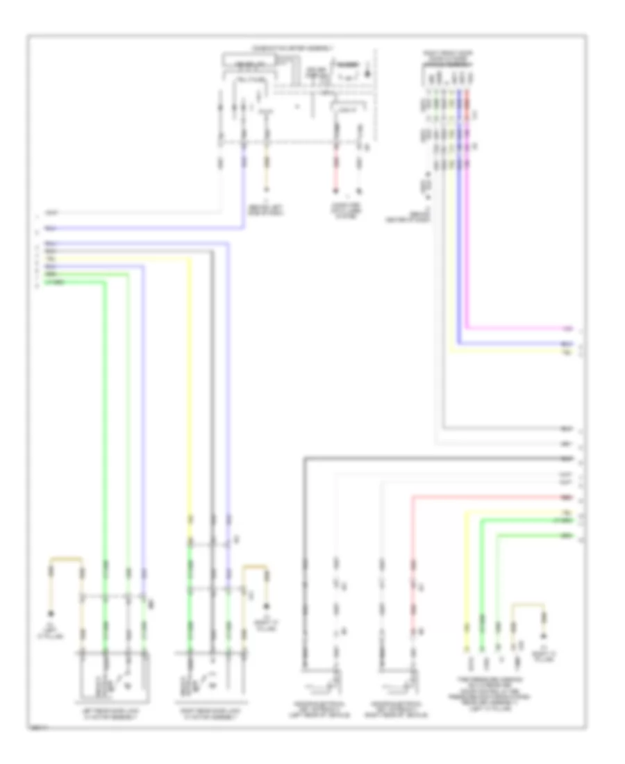
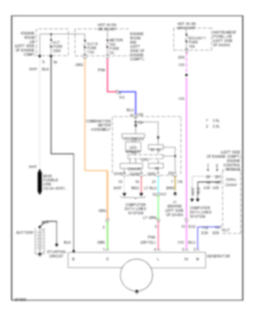
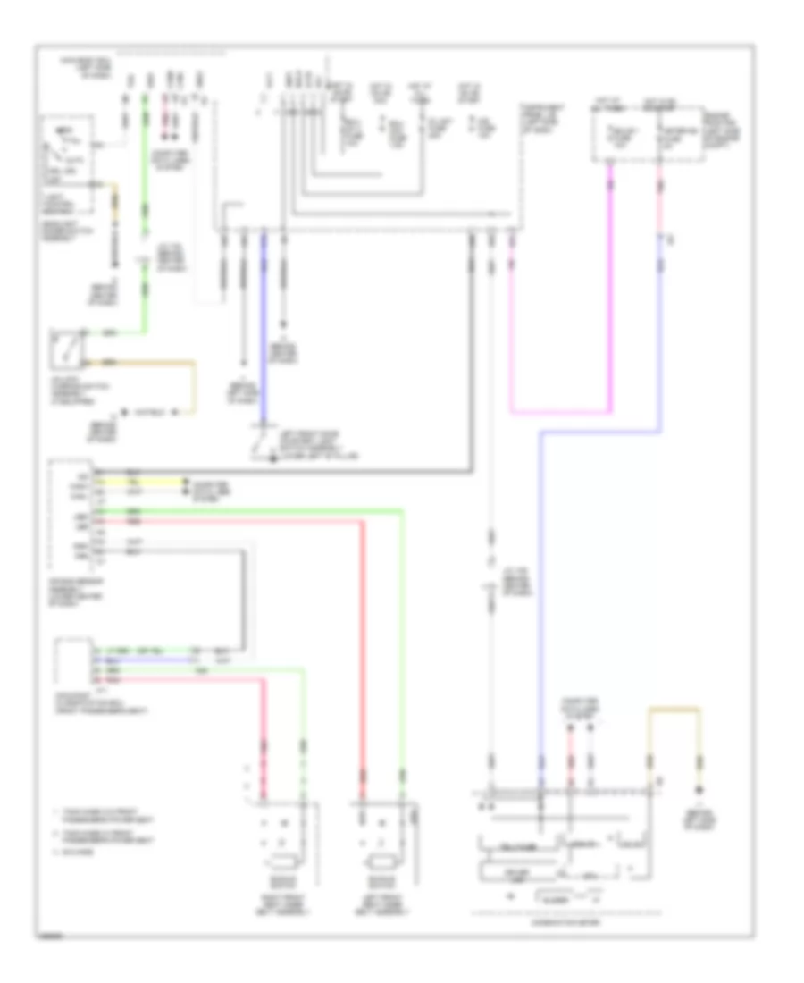
2.5L, Integration Control and Panel Wiring Diagram, Except Hybrid for Toyota Camry LE 2014
List of elements for 2.5L, Integration Control and Panel Wiring Diagram, Except Hybrid for Toyota Camry LE 2014:
- A1 (left front of engine compt)
- Alt
- Alt fuse 120a
- Batt
- Cfan
- Cooling fans system
- D23
- D36
- D38
- D39
- Defogger system
- Defs
- Dim
- Dims
- Drl
- Drls
- Ecu-ig1 1 fuse 10a
- Engine room j/b (left side of engine compt)
- F13
- F14
- F15
- F17
- F18
- Fan2
- Fanh
- Fanl
- Ffgo
- Fn2s
- Fogl
- Fogr
- Fogs
- Gnd1
- Gnd2
- Headlights system
- Hlhl
- Hlhr
- Hot at all times
- Hot w/ ig1 2 relay energized
- Ign
- Instrument panel j/b (left side of dash)
- Integration relay
- J/c a73 (left front of engine compt)
- Main body ecu
- Mhtr
- Pnk
- Power distribution system
- Rdef
- Red
- Rfan
- Tail
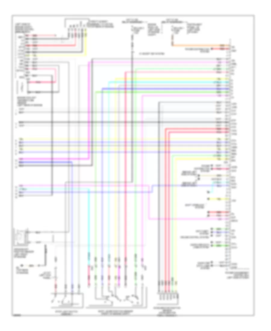
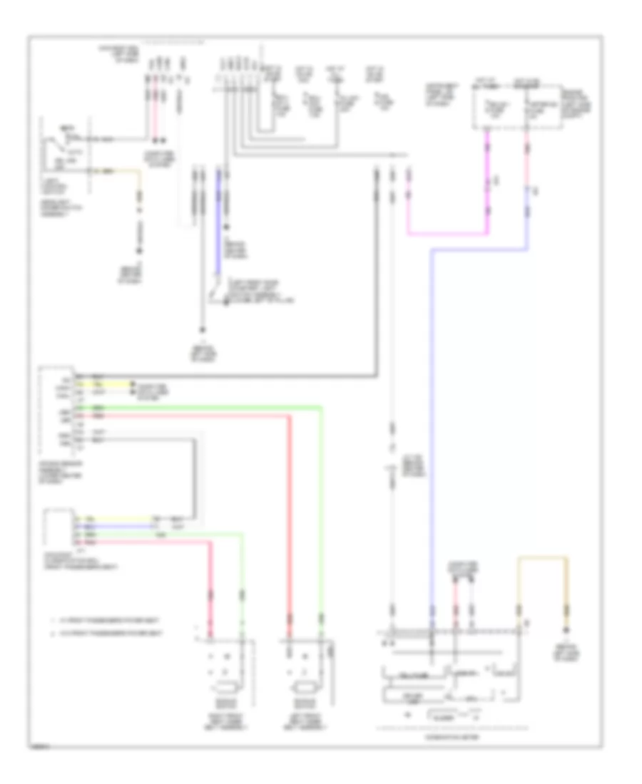
2.5L, Integration Control and Panel Wiring Diagram, Hybrid for Toyota Camry LE 2014
List of elements for 2.5L, Integration Control and Panel Wiring Diagram, Hybrid for Toyota Camry LE 2014:
- A5 (left front of engine compt)
- Alt
- Batt
- Bklp
- Blps
- D23
- D36
- D38
- D39
- Dc/dc fuse 120a
- Defogger system
- Defs
- Dim
- Dims
- Drl
- Drls
- Ecu-ig1 1 fuse 10a
- Engine room j/b (left side of engine compt)
- Exterior lights system
- F13
- F14
- F15
- F18
- Ffgo
- Fogl
- Fogr
- Fogs
- Gnd1
- Gnd2
- Headlights system
- Hlhl
- Hlhr
- Hot at all times
- Hot w/ ig1 2 relay energized
- Ign
- Instrument panel j/b (left side of dash)
- Integration relay
- J/c a73 (left front of engine compt)
- Main body ecu
- Mhtr
- Pnk
- Power distribution system
- Rdef
- Tail
- W/ drl
3.5L
3.5L, Body ECU Wiring Diagram (1 of 2) for Toyota Camry LE 2014
List of elements for 3.5L, Body ECU Wiring Diagram (1 of 2) for Toyota Camry LE 2014:
- A23
- A53
- Acan
- Acc
- Act+
- Act-
- Actd
- Air conditioning & headlights systems
- Altb
- Anti-lock brakes system
- Anti-theft system
- B13
- B26
- B28
- B30
- B34
- B35
- B38
- Becu
- Brx
- Btx
- Bzr
- C15
- C17
- Canh
- Canl
- Cltb
- Clte
- Clts
- D/l-am 1 fuse 20a
- D11
- D12
- D14
- D15
- D20
- D22
- D23
- D25
- D31
- D38
- D39
- Dim
- Domr
- Door locks & anti theft systems
- Door locks & anti-theft systems
- Door locks & interior lights systems
- Door locks & warning systems
- Door locks system
- Drl
- Ecu-acc fuse 7.5a
- Ecu-b1 fuse 10a
- Ecu-ig1 2 fuse 10a
- Engine room r/b (left side of engine compt)
- Ffgo
- Ffog
- Flcy
- Frcy
- Gbs
- Gnd1
- Hcty
- Head
- Headlights system
- Headlights, exterior lights & interior lights systems
- Headlights, interior lights & exterior lights systems
- Horn
- Horns system
- Hot at all times
- Hot in on or acc
- Hot in on or start
- Hrly
- I100
- I103
- I13
- I3 (behind center of dash)
- I93
- I94
- I95
- I96
- I97
- Ile
- Instrument panel j/b (left side of dash)
- Interior lights & anti-theft systems
- Interior lights system
- J/c i93, i94, i95, i96, i97, i100, & i103 (behind left side of dash)
- Ksw
- Lcty
- Lgcy
- Lgyl
- Lin2
- Lsfl
- Lsfr
- Lsr
- Main body ecu (left side of dash)
- Pkb
- Pnk
- Power tops & power windows systems
- Power windows system
- Prg
- Pws
- Rcty
- Rda
- Red
- Starting/charging system
- Tail
- Tr+
- Trk open relay
- Trly
- Ul1
- Ul2
- Ul3
- Warning systems
3.5L, Body ECU Wiring Diagram (2 of 2) for Toyota Camry LE 2014
List of elements for 3.5L, Body ECU Wiring Diagram (2 of 2) for Toyota Camry LE 2014:
- (behind right side of dash)
- (left side of dash) power steering ecu assembly
- 2.5l
- 3.5l
- A/c amplifier assembly (right side of dash)
- A25
- A51
- A52
- Air bag sensor assembly (lower center of dash)
- Anti-theft system
- Brake actuator assembly (right front of engine compt)
- Canh
- Canl
- Certification ecu (right side of dash)
- Clearance warning ecu assembly (behind right side of dash)
- Combination meter assembly
- Data link connector 3 (under passenger's seat)
- Dumy
- Engine control module (left side of engine compt)
- Gnd2
- I1 (behind left side of dash)
- I111
- I12
- I155
- I18
- I67
- I77
- I78
- Ia8
- Ii01
- Ii02
- Ii04
- Ii05
- Ii06
- Ii07
- Ii08
- Ind
- Instrument panel j/b (left side of dash)
- Ij2
- J/c i101,i102, i104, i105 i106, i107, i108 & i111 (behind right side of dash)
- Main body ecu (left side of dash)
- Multi-media receiver sub-assembly module (w/ multi-media module receiver assembly) radio & display receiver assembly (w/o multi-media module receiver assembly)
- Network gateway ecu
- Pnk
- Red
- Steering sensor (steering column)
- W/ multi-media module receiver sub-assembly
- W/o multi-media module receiver sub-assembly w/ display 10 & 6 speaker
- W/o smart key system
- Yaw rate sensor
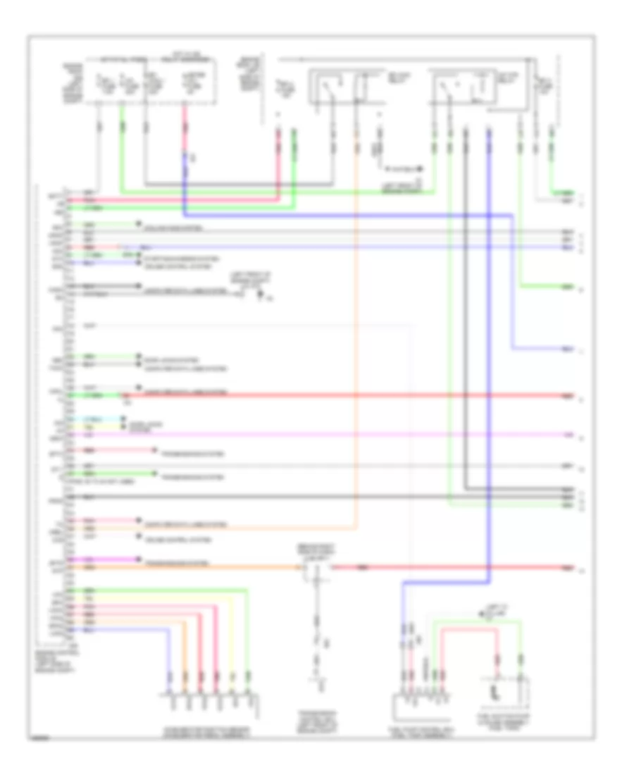
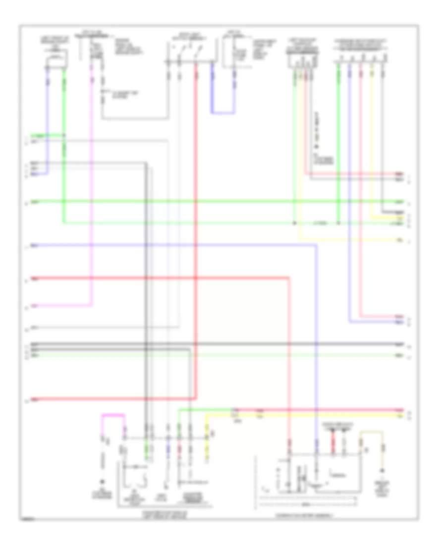
3.5L, Integration Control and Panel Wiring Diagram for Toyota Camry LE 2014
List of elements for 3.5L, Integration Control and Panel Wiring Diagram for Toyota Camry LE 2014:
- A1 (left front of engine compt)
- Air conditioning system
- Alt
- Alt fuse 120a
- Batt
- D23
- D36
- D38
- D39
- Defogger system
- Defs
- Dim
- Dims
- Drl
- Drls
- Ecu-ig1 1 fuse 10a
- Engine room j/b (left side of engine compt)
- F13
- F14
- F15
- F18
- Ffgo
- Fogl
- Fogr
- Fogs
- Gnd1
- Gnd2
- Headlights system
- Hlhl
- Hlhr
- Hot at all times
- Hot w/ ig1 2 relay energized
- Ign
- Instrument panel j/b (left side of dash)
- Integration relay
- J/c a73 (left front of engine compt)
- Main body ecu
- Mcls
- Mgct
- Mhtr
- Pnk
- Power distribution system
- Rdef
- Tail
COMPUTER DATA LINES
Computer Data Lines Wiring Diagram, Except Hybrid (1 of 2) for Toyota Camry LE 2014
List of elements for Computer Data Lines Wiring Diagram, Except Hybrid (1 of 2) for Toyota Camry LE 2014:
- (behind left side of dash) j/c i93, i94, i95, i96, i97, i100 & i103
- (or red)
- (under passenger's seat) data link connector 3
- 2.5l
- 3.5l
- A/c amplifier (right side of dash)
- A25
- A34
- A70
- Air bag sensor assembly (lower center of dash)
- Bat
- Brake actuator assembly (right front of engine compt)
- Can+
- Can-
- Canh
- Canl
- Certification ecu (right side of dash)
- Clearance warning ecu (behind right side of dash)
- Combination meter
- Dcm (telematics transceiver) (behind right side of dash)
- E1 (top rear of engine)
- E26
- E3 (top rear of engine)
- E76
- Engine control module (left side of engine compt)
- Headlight leveling ecu (behind left side of dash)
- Hot at all times
- I100
- I101
- I102
- I103
- I104
- I105
- I106
- I107
- I108
- I111
- I13
- I135
- I176
- I18
- I3 (behind center of dash)
- I47
- I77
- I78
- I92
- I93
- I94
- I95
- I96
- I97
- Ia3
- Ia8
- Instrument panel j/b (left side of dash)
- Io2
- Ij2
- J/c
- J/c a70 & e76 (left side of engine compt)
- J/c a71 & i92 (behind right side a71
- J/c i101, 102, i104, i105, i106, i107, i108 & i111 (behind right side of dash)
- J/c i124 (behind center of dash)
- Lvl
- Main body ecu (left side of dash)
- O1 (right "c" pillar)
- Obd fuse 10a
- Occupant detection ecu
- Of dash)
- Op4
- Od2
- Pnk
- Power steering ecu (left side of dash)
- Prst
- Red
- Right front seat inner belt assembly
- Sia made
- Sil
- Spdl
- Steering sensor (steering column)
- Tac
- Tach
- Tmmk made w/ front passenger's power seat
- Tmmk made w/o front passenger's power seat
- Transmission control ecu (left front of engine compt)
- Transponder key ecu (w/o smart key system) (behind left center of dash)
- W/ headlight beam level control (automatic)
- W/ safety connect
- W/o safety connect
- D11
- D13
- D19
Computer Data Lines Wiring Diagram, Except Hybrid (2 of 2) for Toyota Camry LE 2014
List of elements for Computer Data Lines Wiring Diagram, Except Hybrid (2 of 2) for Toyota Camry LE 2014:
- A50
- A56
- B26
- Batt
- Ca1h
- Ca1l
- Ca1n
- Ca1p
- Ca2h
- Ca2l
- Ca2n
- Ca2p
- Canh
- Canl
- D31
- Ecu-b 1 fuse 10a
- Ecu-ig1 1 fuse 10a
- Ecu-ig2 2 fuse 7.5a
- Engine room r/b (left side of engine compt)
- Gnd
- Hot at all times
- Hot in on or start
- I155
- I5 (behind right side of dash)
- I67
- Ig1
- Ig2
- Instrument panel j/b (left side of dash)
- Io3
- J/c i124 (behind center of dash)
- J/c i125 (behind center of dash)
- J/c i128 (behind center of dash)
- J/c o30 (right rear of vehicle)
- Junction terminal
- Left blind spot monitor sensor (left side of rear bumper)
- Multi-media module receiver sub-assembly (w/ multi-media module receiver sub-assembly) radio & display receiver assembly (w/o multi-media module receiver sub-assembly w/ display 10 speakers & 6 speakers)
- Network gateway ecu (behind right side of dash)
- Receiver sub-assembly
- Receiver sub-assembly, w/ display 10 speakers & 6 speakers
- Red
- Right blind spot monitor sensor (right side of rear bumper)
- T1 (behind left side of rear bumper)
- To1
- W/ multi-media module
- W/o multi-media module
Computer Data Lines Wiring Diagram, Hybrid (1 of 2) for Toyota Camry LE 2014
List of elements for Computer Data Lines Wiring Diagram, Hybrid (1 of 2) for Toyota Camry LE 2014:
- (behind left side of dash) j/c i93, i94, i95, i96, i97, i109 & i110
- (top rear of engine)
- (under passenger's seat) data link connector 3
- A/c amplifier (right side of dash)
- A25
- A34
- A71
- Aa1
- Bat
- Canh
- Canl
- Cann
- Canp
- Certification ecu (right side of dash)
- Clearance warning ecu (w/ parking assist) (behind right side of dash)
- Dcm (telematics transceiver) (behind right side of dash)
- Ea2
- Ecm (left side of engine compt)
- Headlight leveling ecu (behind left side of dash)
- Hot at all times
- I100
- I101
- I102
- I103
- I104
- I106
- I107
- I109
- I110
- I111
- I135
- I155
- I3 (behind center of dash)
- I67
- I77
- I87
- I92
- I93
- I94
- I95
- I96
- I97
- Ia3
- Ia4
- Ia8
- Instrument panel j/b (left side of dash)
- Io2
- Ij2
- J/c a71 & i92 (left kick panel) i92
- J/c i100, i101, 102, i103, i104, i106, i107 & i111 (behind right side of dash)
- J/c i124 (behind center of dash)
- J/c i160 (behind center of dash)
- Lvl
- Multi-media module receiver sub-assembly (w/ multi-media module receiver sub-assembly) radio & display receiver assembly (w/o multi-media module receiver sub-assembly w/ display 10 speakers & 6 speakers)
- O1 (right "c" pillar)
- Obd fuse 10a
- Occupant detection ecu
- Op4
- Od2
- Pnk
- Power steering ecu (left side of dash)
- Prst
- Receiver sub-assembly
- Receiver sub-assembly, w/ display 10 speakers & 6 speakers
- Red
- Right front seat inner belt assembly
- Sil
- Spdl
- Steering sensor (steering column)
- Tac
- Tach
- W/ front passenger's power seat
- W/ headlight beam level control (automatic)
- W/ multi-media module
- W/ safety connect
- W/o front passenger's power seat
- W/o mult-media module
- W/o safety connect
- D11
- D13
Computer Data Lines Wiring Diagram, Hybrid (2 of 2) for Toyota Camry LE 2014
List of elements for Computer Data Lines Wiring Diagram, Hybrid (2 of 2) for Toyota Camry LE 2014:
- (left side of dash) j/c a72
- Air bag sensor assembly (lower center of dash)
- Ca1h
- Ca1l
- Ca1n
- Ca1p
- Ca2h
- Ca2l
- Ca2n
- Ca2p
- Ca3n
- Ca3p
- Canh
- Canl
- Combination meter assembly
- I13
- I18
- I47
- Ia4
- Io3
- J/c o30 (w/ blind spot monitor system) (right rear of vehicle)
- Junction terminal (left rear of vehicle)
- Left blind spot monitor sensor (left side of rear bumper)
- Main body ecu (left side of dash)
- Pnk
- Power management control ecu (left side of dash)
- Red
- Right blind spot monitor sensor (right side of rear bumper)
- Skid control ecu w/ actuator (brake booster w/ master cylinder assembly) (right side of engine compt)
- T1 (behind left side of rear bumper)
- To1
COOLING FAN
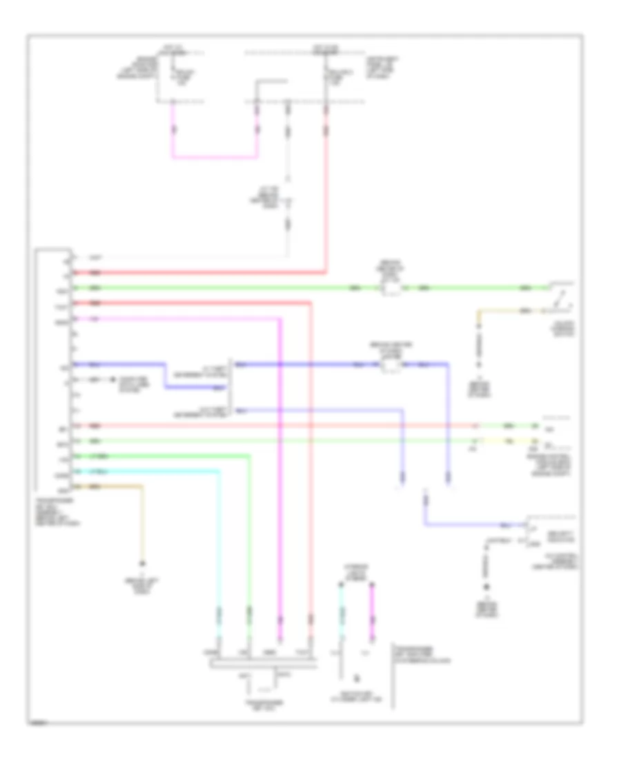
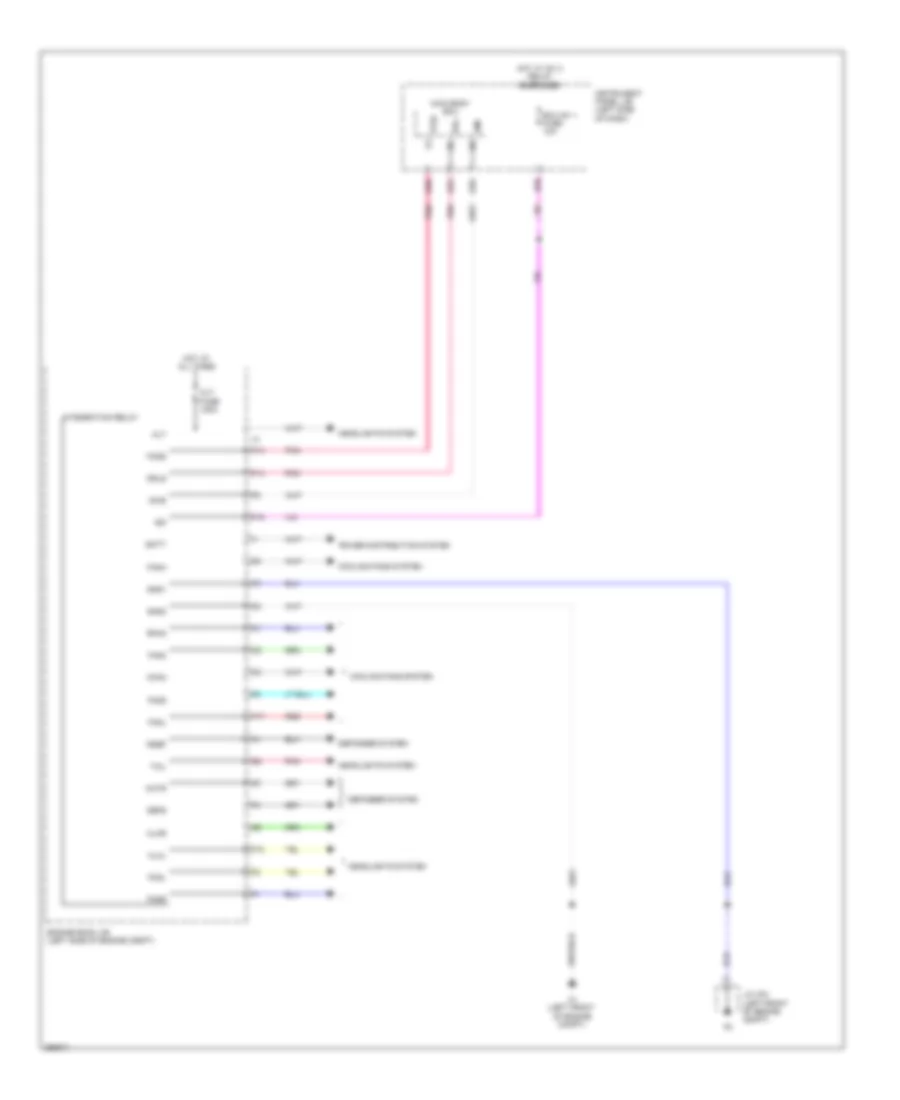
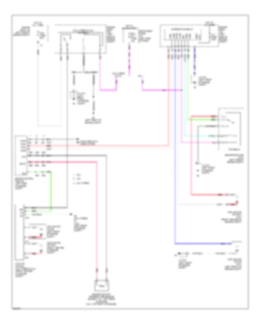
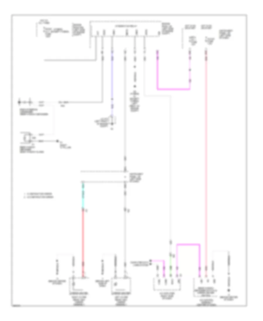
Cooling Fan Wiring Diagram for Toyota Camry LE 2014
List of elements for Cooling Fan Wiring Diagram for Toyota Camry LE 2014:
- (2.5l hybrid & 3.5l) fan relay
- +b1
- 2.5l
- 2.5l hybrid
- 2.5l hybrid & 3.5l
- 3.5l
- A10
- A25
- A5 (2.5l hybrid) a1 (3.5l) (left front of engine compt)
- A5 (left front of engine compt)
- Alt
- Alt fuse 120a
- Canh
- Canl
- Cfan
- Computer data lines system
- Cooling fan ecu (2.5l hybrid & 3.5l) (front center of engine compt)
- Cooling fan motor (2.5l) (left front of engine compt)
- Cooling fan motor (left front of engine compt)
- Cooling fan motor 2 (2.5l) (front center of engine compt)
- Cooling fan motor 2 (front center of engine compt)
- D36
- E26
- E28
- Ecu- igi 1 fuse 10a
- Engine control module (left side of engine compt)
- Engine coolant temperature sensor (except 3.5l: left rear of engine) (3.5l: top front of engine)
- Engine room j/b (left side of engine compt)
- Engine room r/b (2.5l) (left side of engine compt)
- Engine room r/b (left side of engine compt)
- Ethw
- F15
- F17
- Fan fuse 50a
- Fan relay
- Fan2
- Fanh
- Fanl
- Fn2s
- Gnd1
- Hot at all times
- Hot in on or start
- Ign
- Instrument panel j/b (left side of dash)
- Integration relay
- J/c a73 (left front of engine compt)
- Pnk
- Red
- Rfan
- Rfc
- Thw
- Z14
- Z15
CRUISE CONTROL
Cruise Control Wiring Diagram, Except Hybrid (1 of 2) for Toyota Camry LE 2014
List of elements for Cruise Control Wiring Diagram, Except Hybrid (1 of 2) for Toyota Camry LE 2014:
- +b2
- +bm
- 2.5l
- 3.5l
- A1 (left front of engine compt)
- A25
- Accelerator pedal sensor assembly
- Batt
- Bkup lp fuse 7.5a
- C10
- Canh
- Canl
- Ccs
- Computer data lines system
- D30
- D33
- E26
- Ea2
- Ecu-ig2 fuse 7.5a
- Efi 1 fuse 7.5a
- Efi 2 fuse 15a
- Efi main 1 fuse 30a
- Efi main relay
- Engine control module (left side of engine compt)
- Engine room j/b (left side of engine compt)
- Engine room r/b (left side of engine compt)
- Epa
- Epa2
- Eta
- Etcs fuse 10a
- Ge01
- Hot at all times
- Hot in on or start
- Ia3
- Ic1
- Ic2
- Igsw
- Instrument panel j/b (left side of dash)
- J/c a71 (behind right side of dash)
- J/c a73 (left front of engine compt)
- Mrel
- Park/neutral position switch (top of transaxle)
- Pnk
- R p
- Red
- Spd
- St1-
- Stop fuse 7.5a
- Stop light switch assembly
- Stp
- Throttle body assembly (top rear of engine)
- Transmission control ecu (3.5l) (left front of engine compt)
- Transmissions system
- Vcp2
- Vcpa
- Vcta
- Vpa
- Vpa2
- Vta
- Vta1
- Vta2
- W/ headlight beam level control
- W/ smart key system
Cruise Control Wiring Diagram, Except Hybrid (2 of 2) for Toyota Camry LE 2014
List of elements for Cruise Control Wiring Diagram, Except Hybrid (2 of 2) for Toyota Camry LE 2014:
- (left front wheel hub assembly) left front speed sensor
- (left rear wheel hub assembly) left rear speed sensor
- (left side of engine compt) j/c a70 & e76
- (right front wheel hub assembly) right front speed sensor
- (right rear wheel hub assembly) right rear speed sensor
- +bs
- +res
- -set
- 5v 1c
- A3 (right front of engine compt)
- A70
- Abs 2 fuse 30a
- An1
- Brake actuator assembly (right front of engine compt)
- Can i/f
- Cancel
- Canh
- Canl
- Combination meter assembly
- Computer data lines system
- Cpu
- Cruise control main switch
- E1 (3.5l) e3 (2.5l) (top rear of engine)
- E76
- Engine room r/b (left side of engine compt)
- Fl+
- Fl-
- Fr+
- Fr-
- Gnd1
- Gnd2
- Hot at all times
- Hot in on or start
- I1 (behind left side of dash)
- I18
- I28
- Ia3
- Ia8
- J/c i124 (behind center of dash)
- J/c i176
- Led driver
- Meter-ig2 fuse 5a
- Oa1
- On-off
- Pnk
- Red
- Rl+
- Rl-
- Rr+
- Rr-
- Sp1
- Spiral cable sub-assembly
- Ho1
- In1
Cruise Control Wiring Diagram, Hybrid (1 of 2) for Toyota Camry LE 2014
List of elements for Cruise Control Wiring Diagram, Hybrid (1 of 2) for Toyota Camry LE 2014:
- +b2
- +bm
- 5v 1c
- A25
- A5 (left front of engine compt)
- Batt
- C10
- Can i/f
- Canh
- Canl
- Combination meter
- Computer data lines system
- Cpu
- E01
- E28
- E3 (top rear of engine)
- Ea2
- Efi 1 fuse 7.5a
- Efi 2 fuse 15a
- Efi main 1 fuse 30a
- Efi main relay
- Engine control module (left side of engine compt)
- Engine room j/b (left side of engine compt)
- Engine room r/b (left side of engine compt)
- Engine room r/b 2 (right side of engine compt)
- Eta
- Etcs fuse 10a
- Ge01
- Hot at all times
- Hot in on or start
- Hot w/ igct relay energized
- I1 (behind left side of dash)
- I18
- Ia3
- Ia8
- J/c i124 (behind center of dash)
- Led driver
- Meter-ig2 fuse 5a
- Mrel
- Pm igct fuse 7.5a
- Pnk
- Red
- Throttle body assembly (top rear of engine)
- Vcta
- Vta
- Vta1
- Vta2
Cruise Control Wiring Diagram, Hybrid (2 of 2) for Toyota Camry LE 2014
List of elements for Cruise Control Wiring Diagram, Hybrid (2 of 2) for Toyota Camry LE 2014:
- (left front wheel hub assembly) left front speed sensor
- (left rear wheel hub assembly) left rear speed sensor
- (right front wheel hub assembly) right front speed sensor
- (right rear wheel hub assembly) right rear speed sensor
- +res
- -set
- A39
- A5 (left front of engine compt)
- Accelerator pedal sensor assembly
- An1
- Ca1h
- Ca1l
- Cancel
- Ccs
- Computer data lines system
- Cruise control main switch
- D30
- Ea2
- Ea3
- Ecu-ig2 fuse 7.5a
- Engine room j/b (left side of engine compt)
- Ep1
- Ep2
- Fl+
- Fl-
- Fr+
- Fr-
- Hot at all times
- Hot in on or start
- I1 (behind left side of dash)
- I28
- Instrument panel j/b (left side of dash)
- J/c a71 (left kick panel)
- Nca
- Oa1
- On-off
- Pnk
- Power management control ecu (left side of dash)
- Red
- Rl+
- Rl-
- Rr+
- Rr-
- Shift lever position sensor (front of engine compt)
- Skid control ecu w/ actuator (brake booster w/ master cylinder assembly) (right side of engine compt)
- Sp1
- Spdi
- Spiral cable sub assembly
- St1-
- Stop fuse 7.5a
- Stop light switch assembly
- Stp
- Vcp1
- Vcp2
- Vpa1
- Vpa2
- Ho1
- In1
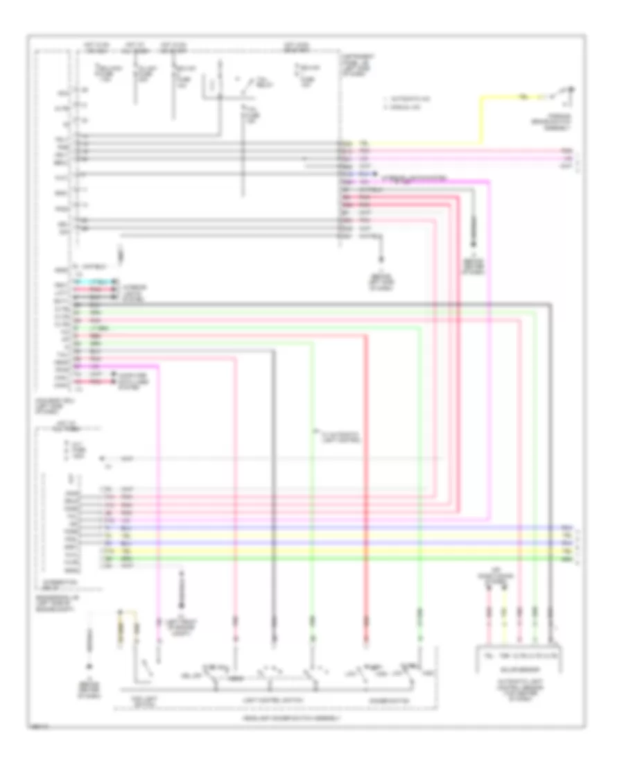
DEFOGGERS
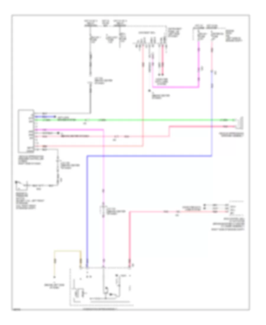
Defoggers Wiring Diagram for Toyota Camry LE 2014
List of elements for Defoggers Wiring Diagram for Toyota Camry LE 2014:
- (except hybrid)
- (hybrid)
- A/c amplifier (right side of dash)
- A/c control assembly (center of dash)
- A/c-ig1 fuse 7.5a
- A5 (hybrid) a1 (except hybrid) (left front of engine compt)
- Alt
- An2
- B22
- B24
- B25
- Canh
- Canl
- Computer data lines system
- D21
- D36
- Dc/dc alt fuse 120a
- Defs
- Ecu- ig1 1 fuse 10a
- Engine room j/b (left side of engine compt)
- Engine room r/b (left side of engine compt)
- F15
- Gnd
- Gnd1
- Gnd2
- Hot at all times
- Hot in on or start
- I1 (behind left side of dash)
- I3 (behind center of dash)
- I77
- Ia8
- Ig+
- Ign
- Instrument panel j/b (left side of dash)
- Integration relay
- J/c a73 (left front of engine compt)
- Ji1
- Ki2
- Left outer rear view mirror assembly
- Lin1
- Mhtr
- Mirror heater
- N29
- P1 (right "c" pillar)
- Radio steering condenser (rear window defogger)
- Rdef
- Rdfg
- Rear window defogger (back window glass)
- Rear window defogger switch & mirror heater switch
- Red
- Right outer rear view mirror assembly
- W/ retractor mirror
- W/o retractor mirror
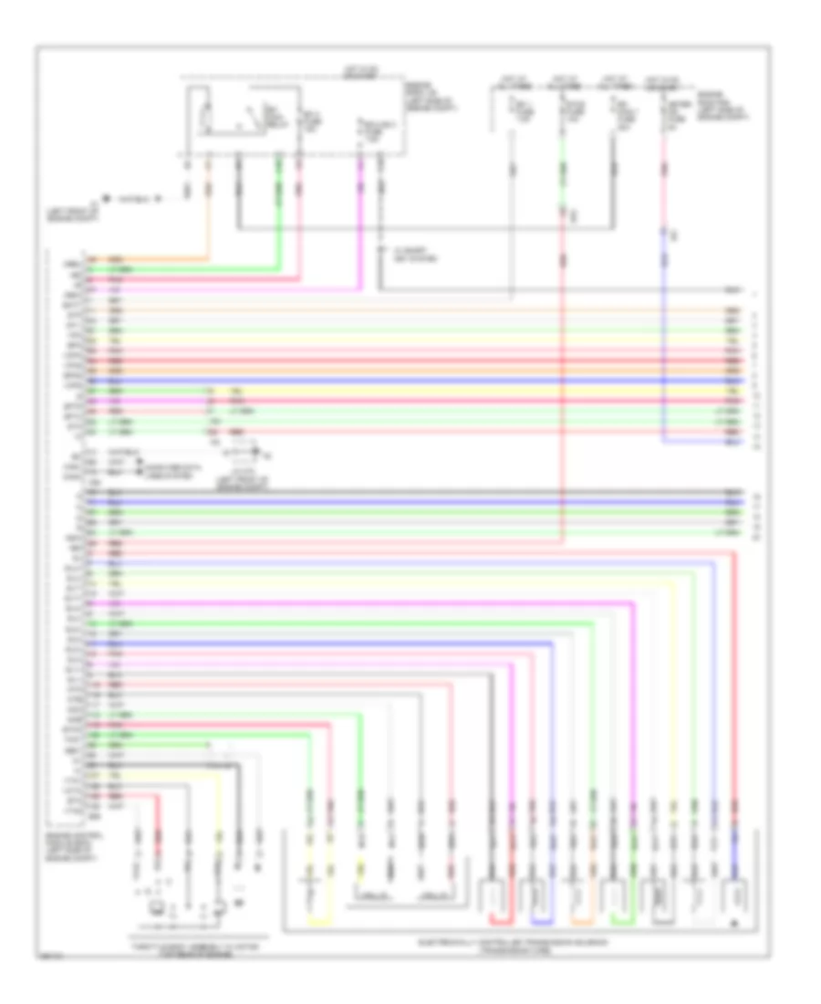
ELECTRONIC POWER STEERING
2.5L
2.5L, Electronic Power Steering Wiring Diagram, Except Hybrid for Toyota Camry LE 2014
List of elements for 2.5L, Electronic Power Steering Wiring Diagram, Except Hybrid for Toyota Camry LE 2014:
- (behind center of dash) i3
- 5v ic
- A44
- A56
- B26
- Bat
- Buzzer
- Can i/f
- Canh
- Canl
- Combination meter assembly
- Computer data lines system
- Cpu
- D31
- Ecu-b 1 fuse 10a
- Ecu-ig1 1 fuse 10a
- Electric power steering column sub- assembly
- Engine room r/b (left side of engine compt)
- Eps fuse 80a
- Eps-ig1 fuse 7.5a
- Ess
- Hall ic 1
- Hall ic 2
- Hot at all times
- Hot in on or start
- I/f
- I1 (behind left side of dash)
- I18
- Ia2
- Ia3
- Ig+
- Instrument panel j/b (left side of dash)
- Ij1
- Ij2
- J/c i124 (behind center of dash)
- J/c i125 (behind center of dash)
- J1 (left side of dash)
- Led driver
- Meter-ig2 fuse 5a
- Pgnd
- Pig
- Pnk
- Power steering ecu (left side of dash)
- Power steering motor (w/ brush type motor) (left side of dash)
- Red
- Steering sensor (steering column)
- Telltales
- Torque sensor
- Trq1 z16
- Trq2
- Trqg
- Trqv
- W/ brushless type motor
- Z18
2.5L, Electronic Power Steering Wiring Diagram, Hybrid for Toyota Camry LE 2014
List of elements for 2.5L, Electronic Power Steering Wiring Diagram, Hybrid for Toyota Camry LE 2014:
- (behind center of dash) i3
- 5v ic
- A44
- A56
- Aa1
- B26
- Bat
- Buzzer
- Can i/f
- Canh
- Canl
- Combination meter assembly
- Computer data lines system
- Cpu
- D31
- Ecu-b 1 fuse 10a
- Ecu-ig1 1 fuse 10a
- Engine room r/b (left side of engine compt)
- Eps fuse 80a
- Eps-ig1 fuse 7.5a
- Ess
- Hot at all times
- Hot in on or start
- Hybrid
- I/f
- I1 (behind left side of dash)
- I18
- Ia2
- Ia3
- Ig+
- Instrument panel j/b (left side of dash)
- Ij1
- Ij2
- J/c i124 (behind center of dash)
- J/c i125 (behind center of dash)
- J1 (left side of dash)
- Led driver
- Meter-ig2 fuse 5a
- Pgnd
- Pha
- Phb
- Phc
- Pig
- Pnk
- Power steering ecu (left side of dash)
- Power steering motor assembly
- Red
- Rzcs1
- Rzcs2
- Rzsn1
- Rzsn2
- Rzv1
- Rzv2
- Steering sensor (steering column)
- Telltales
- Torque sensor
- Trq1
- Trq2
- Trqf
- Trqg
- Trqv
3.5L
3.5L, Electronic Power Steering Wiring Diagram for Toyota Camry LE 2014
List of elements for 3.5L, Electronic Power Steering Wiring Diagram for Toyota Camry LE 2014:
- (behind center of dash) i3
- 5v ic
- A44
- A56
- Aa1
- B26
- Bat
- Buzzer
- Can i/f
- Canh
- Canl
- Combination meter assembly
- Computer data lines system
- Cpu
- D31
- Ecu-b 1 fuse 10a
- Ecu-ig1 1 fuse 10a
- Engine room r/b (left side of engine compt)
- Eps fuse 80a
- Eps-ig1 fuse 7.5a
- Ess
- Hot at all times
- Hot in on or start
- Hybrid
- I/f
- I1 (behind left side of dash)
- I18
- Ia2
- Ia3
- Ig+
- Instrument panel j/b (left side of dash)
- Ij1
- Ij2
- J/c i124 (behind center of dash)
- J/c i125 (behind center of dash)
- J1 (left side of dash)
- Led driver
- Meter-ig2 fuse 5a
- Pgnd
- Pha
- Phb
- Phc
- Pig
- Pnk
- Power steering ecu (left side of dash)
- Power steering motor assembly
- Red
- Rzcs1
- Rzcs2
- Rzsn1
- Rzsn2
- Rzv1
- Rzv2
- Steering sensor (steering column)
- Telltales
- Torque sensor
- Trq1
- Trq2
- Trqf
- Trqg
- Trqv
ENGINE PERFORMANCE
2.5L
2.5L, Engine Performance Wiring Diagram (1 of 6) for Toyota Camry LE 2014
List of elements for 2.5L, Engine Performance Wiring Diagram (1 of 6) for Toyota Camry LE 2014:
- +b2
- A1 (left front of engine compt)
- A25
- Accelerator position sensor (accelerator pedal assembly)
- An1
- Batt
- Brake actuator assembly (right front of engine compt)
- C/opn relay
- C10
- Canh
- Canister pressure sensor
- Canister pump module (left rear of vehicle)
- Canl
- Ccs
- Computer data lines system
- Cruise control system
- Door locks & anti-theft systems
- Door locks system
- E1 (top rear of engine)
- Ea2
- Efi 1 fuse 7.5a
- Efi 2 fuse 15a
- Efi 3 fuse 7.5a
- Efi main 2 relay
- Efi main relay
- Efi- main 1 fuse 30a
- Efi- main 2 fuse 20a
- Engine control module (left side of engine compt)
- Engine room j/b (left side of engine compt)
- Engine room r/b (left side of engine compt)
- Epa
- Epa2
- Eppm
- Fanh
- Fanl
- Hot at all times
- I3 (behind center of dash)
- Ia3
- Ia8
- Ig 2 relay
- Ig2- main fuse 25a
- Igsw
- Imi
- Imo
- Inj fuse 7.5a
- J/c a73 (left front of engine compt)
- J/c i126 (behind center of dash)
- Leak detection pump
- Mpmp
- Mrel
- Neo
- Pnk
- Ppmp
- Red
- Sftd
- Sftu
- Spd
- St1-
- Sta
- Stp
- Tach
- Transmission control switch (lower shift lever assembly)
- Vcp2
- Vcpa
- Vcpp
- Vent valve
- Vpa
- Vpa2
- Vpmp
- W/ headlight beam level control
- W/ paddle shift switch
- W/ smart key system
- W/o paddle shift switch
- W/o smart key system
2.5L, Engine Performance Wiring Diagram (2 of 6) for Toyota Camry LE 2014
List of elements for 2.5L, Engine Performance Wiring Diagram (2 of 6) for Toyota Camry LE 2014:
- (fuel tank) fuel suction pump & gauge assembly
- 5v 1c
- A43
- A56
- An1
- Can i/f
- Certification ecu (w/ smart key system) (right side of dash)
- Combination meter
- Computer data lines system
- Cpu
- D24
- D30
- Ecu-ig1 1 fuse 10a
- Ecu-ig2 1 fuse 7.5a
- Ecu-ig2 3 fuse 7.5a
- Engine room j/b (left side of engine compt)
- Engine room r/b (left side of engine compt)
- Etcs fuse 10a
- Fuel pump
- Gauge
- Hot at all times
- Hot in on or start
- I/f
- I1 (behind left side of dash)
- I18
- Ia3
- Ig2d
- Instrument cluster system
- Instrument panel j/b (left side of dash)
- J/c a71 (behind right side of dash)
- J/c i124 (behind center of dash)
- Malfunction indicator lamp
- Meter-ig2 fuse 5a
- N1 (left "c" pillar)
- Pnk
- Red
- Sta
- Star
- Stop fuse 7.5a
- Stop light switch assembly
- W/ smart key system
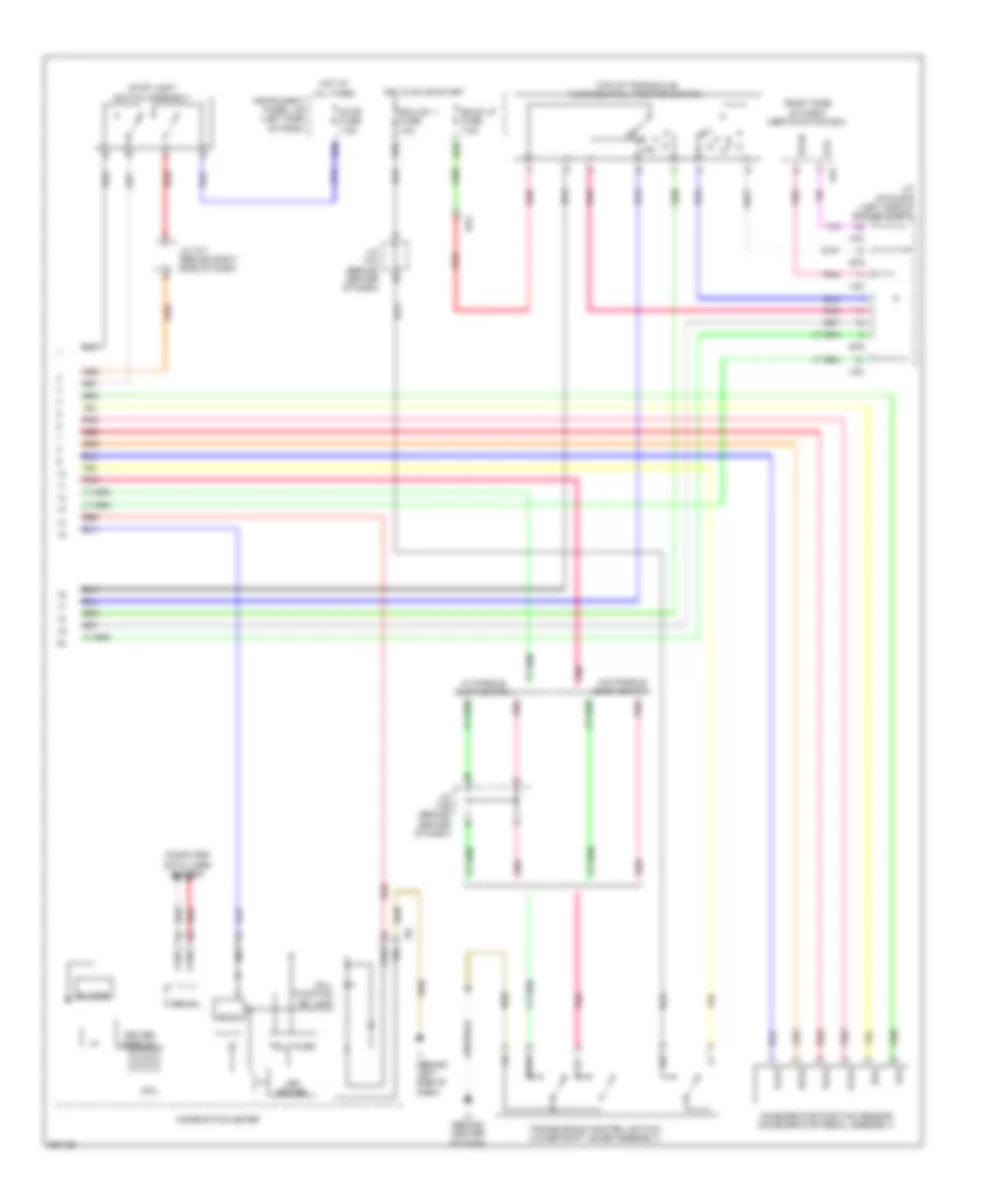
2.5L, Engine Performance Wiring Diagram (3 of 6) for Toyota Camry LE 2014
List of elements for 2.5L, Engine Performance Wiring Diagram (3 of 6) for Toyota Camry LE 2014:
- +bm
- E02
- E26
- E3 (top rear of engine)
- Ea2
- Electronically controlled transmission solenoid
- Engine control module (left side of engine compt)
- Ha1a
- Hall ic
- Ht1b
- Ia1+
- Ia1-
- Ncb
- Nco
- Ntb
- Nto
- Oil
- Pnk
- Red
- Sl1+
- Sl1-
- Sl2+
- Sl2-
- Sl3+
- Sl3-
- Sl4+
- Sl4-
- Slt+
- Slt-
- Slu+
- Slu-
2.5L, Engine Performance Wiring Diagram (4 of 6) for Toyota Camry LE 2014
List of elements for 2.5L, Engine Performance Wiring Diagram (4 of 6) for Toyota Camry LE 2014:
- (in exhaust manifold) oxygen sensor (bank 1 sensor 2)
- (on intake manifold) intake air control valve actuator
- (top of intake manifold)
- (top of valve cover)
- E1 (top rear of engine)
- Engine room j/b (left side of engine compt)
- Ey1
- Fuel injector
- Gnd
- Hot in on or start
- Ht1b
- Igf
- Ign fuse 15a
- Ignition coil
- Igt1
- Igt2
- Igt3
- Igt4
- Out
- Ox1b
- Pnk
- Red
- Sensor
- Vdd
2.5L, Engine Performance Wiring Diagram (5 of 6) for Toyota Camry LE 2014
List of elements for 2.5L, Engine Performance Wiring Diagram (5 of 6) for Toyota Camry LE 2014:
- (left side of engine compt) engine control module
- (near top left rear of engine) air fuel ratio sensor (bank 1 sensor 1)
- (top of transaxle)
- (top rear of engine) throttle body assembly
- A1a+
- A1a-
- A70
- Acis
- Back up fuse 7.5a
- Compt)
- D33
- E01
- E04
- E26
- E3 (top rear of engine)
- Ea2
- Eia1
- Eknk
- Engine control module (left side of engine compt)
- Eta
- Ex1b
- Geo1
- Ha1a
- Hot in on or start
- Iac1
- Ic1
- Ic2
- Igf1
- Igt1
- Igt2
- Igt3
- Igt4
- Instrument panel j/b (left side of dash)
- J/c a70 & e76 (left side of engine e76
- Knk1
- Me01
- N r
- Nca
- Nsw
- Oe1+
- Ole-
- Park/neutral position switch
- Pnk
- Prg
- R n
- Red
- Vcia
- Vcta
- Vsv (acis) (right front of engine)
- Vsv (purge) (left rear of engine compt)
- Vta1
- Vta2
2.5L, Engine Performance Wiring Diagram (6 of 6) for Toyota Camry LE 2014
List of elements for 2.5L, Engine Performance Wiring Diagram (6 of 6) for Toyota Camry LE 2014:
- (center of engine) knock control sensor (bank 1)
- (left front of engine) crankshaft position sensor
- (left side of engine compt) j/c e76
- Alt
- Camshaft timing oil control valve (exhaust side) (front of right cylinder head)
- Camshaft timing oil control valve (intake side) (front of right cylinder head)
- E26
- E2g
- E3 (top rear of engine)
- Engine control module (left side of engine compt)
- Engine coolant temperature sensor (left rear of engine)
- Etha
- Etho
- Ethw
- Ev1+
- Ev1-
- Ey1
- Intake mass air flow meter sub-assembly (in engine air intake duct)
- Nca
- Ncb
- Nco
- Ne+
- Ne-
- Ntb
- Nto
- Oc1+
- Oc1-
- Ox1b
- Pnk
- Red
- Starting/charging system
- Tha
- Tho1
- Thw
- Vc2
- Vce1
- Vcv1
- Vv1+
- Vv1-
- Vve+
- Vve-
- Vvt sensor (bank 1 exhaust side) (rear of engine)
- Vvt sensor (bank 1 intake side) (right rear of engine)
2.5L HYBRID
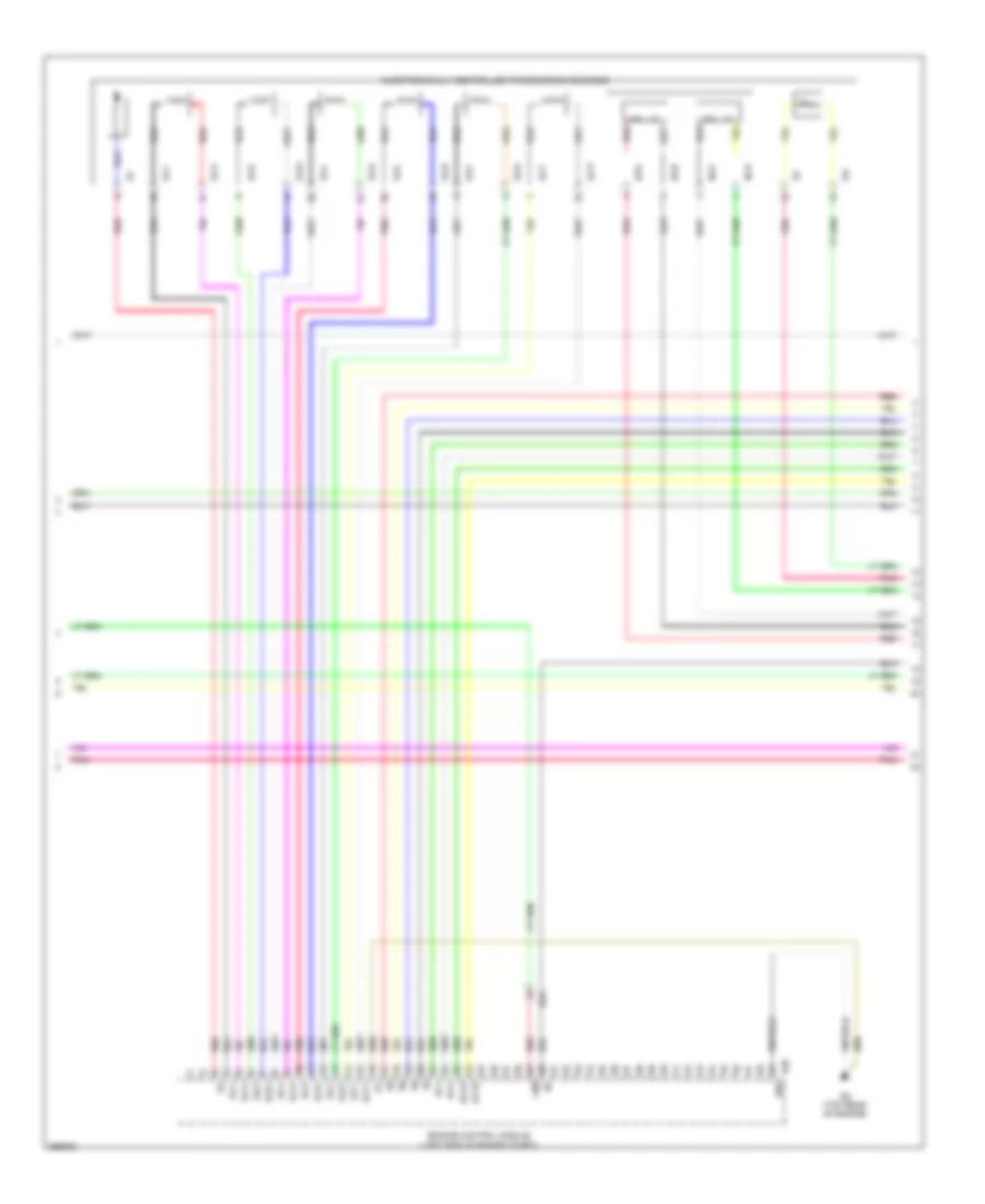
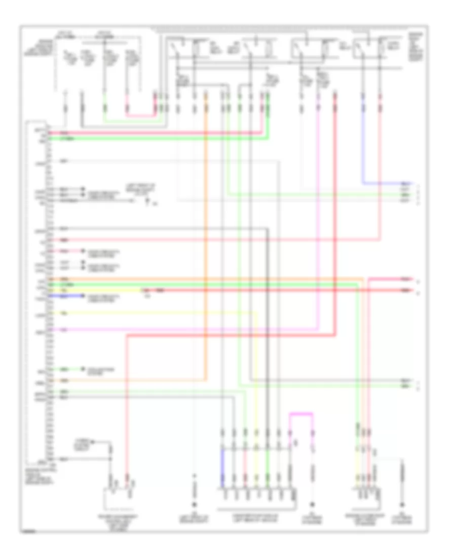
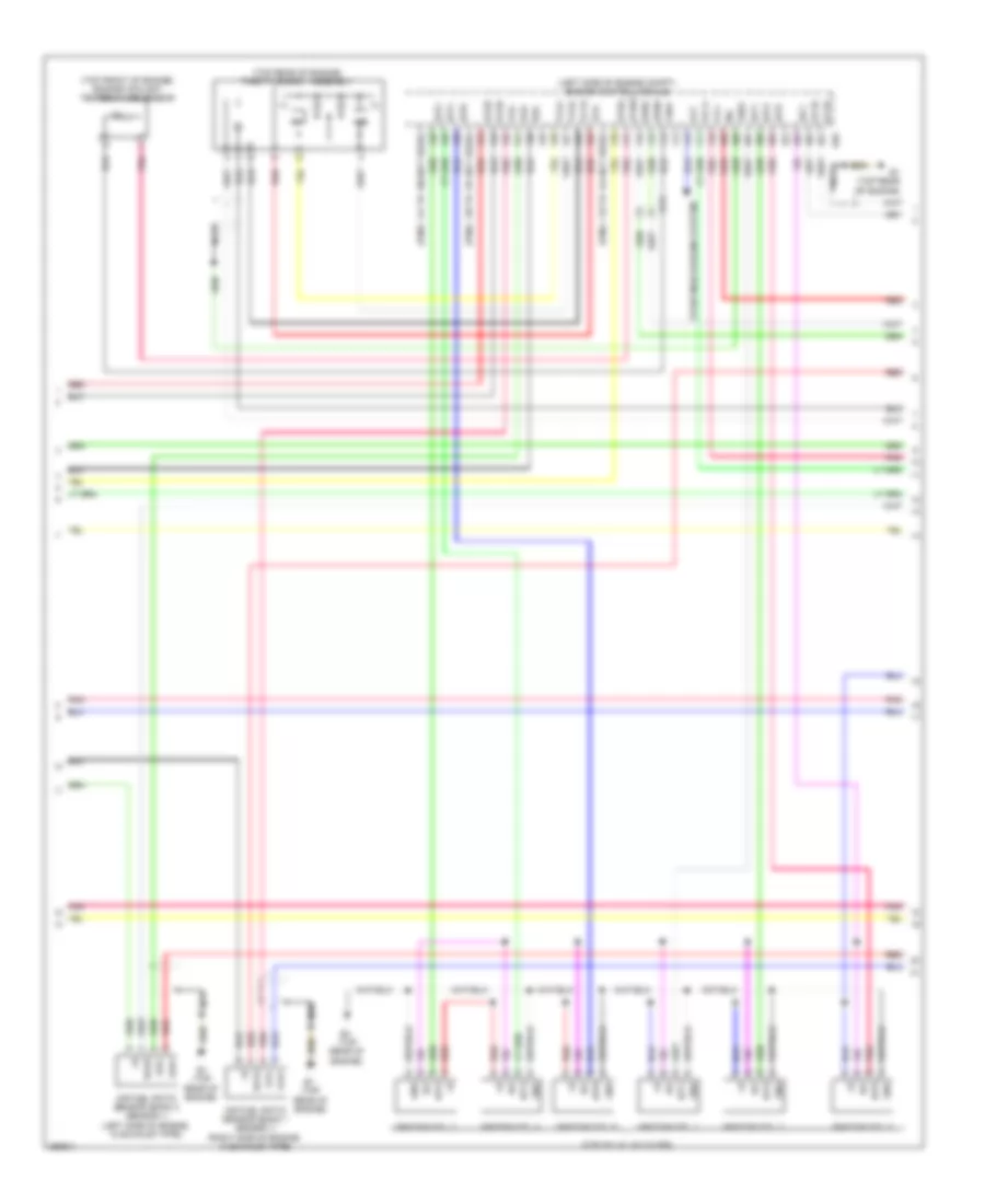
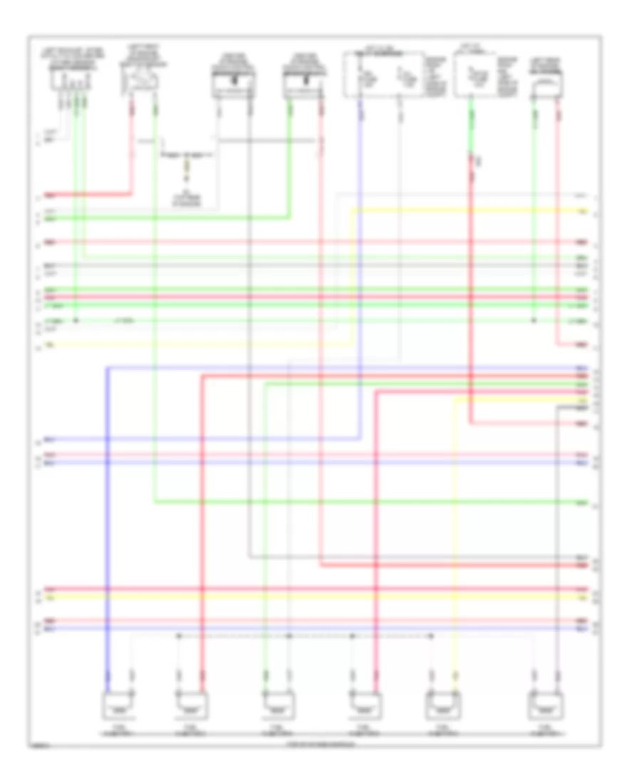
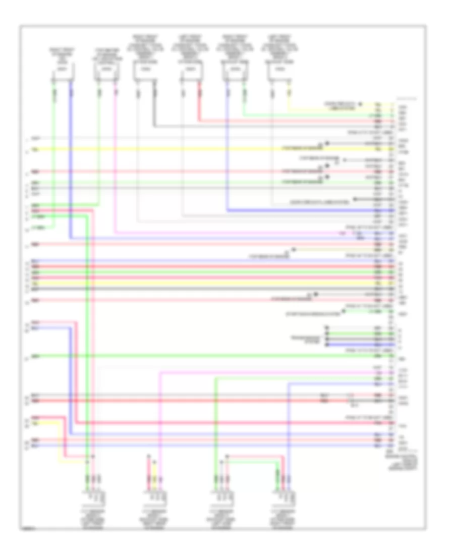
2.5L Hybrid, Engine Controls Wiring Diagram (1 of 4) for Toyota Camry LE 2014
List of elements for 2.5L Hybrid, Engine Controls Wiring Diagram (1 of 4) for Toyota Camry LE 2014:
- (left front of engine compt) j/c a73
- +b2
- A25
- A38
- A39
- A5 (left front of engine compt)
- An1
- Batt
- C/opn relay
- C10
- Canh
- Canister pump module (left rear of vehicle)
- Canl
- Cann
- Canp
- Computer data lines system
- Cooling fans system
- E1 (top rear of engine)
- E3 (top rear of engine)
- Ea2
- Ecu- ig2 3 fuse 7.5a
- Efi 1 fuse 7.5a
- Efi 2 fuse 15a
- Efi 3 fuse 7.5a
- Efi main 2 relay
- Efi main relay
- Efi- main 1 fuse 30a
- Efi- main 2 fuse 20a
- Engine control module (left side of engine compt)
- Engine room j/b (left side of engine compt)
- Engine room r/b (left side of engine compt)
- Engine water pump (left front of engine)
- Eppm
- G2o
- Hot at all times
- Hybrid system circuit
- Ia3
- Ig 2 relay
- Ig2- main fuse 25a
- Ig2d
- Igsw
- Inj fuse 7.5a
- Mgnd
- Mpmp
- Mrel
- Mtrb
- Nwp
- Pgnd
- Pnk
- Power management control ecu (left side of dash)
- Ppmp
- Red
- Rfc
- Sgnd
- Swp
- Tach
- Vcc
- Vcpp
- Vgnd
- Vlvb
- Vout
- Vpmp
- Wpi
- Wpo
2.5L Hybrid, Engine Controls Wiring Diagram (2 of 4) for Toyota Camry LE 2014
List of elements for 2.5L Hybrid, Engine Controls Wiring Diagram (2 of 4) for Toyota Camry LE 2014:
- (right rear of engine) vvt sensor (camshaft position sensor)
- (top of valve cover)
- A5 (left front of engine compt)
- An1
- Can i/f
- Canh
- Canl
- Chk
- Combination meter assembly
- Computer data lines system
- Cpu
- E1 (top rear of engine)
- Ea2
- Eng w/ pmp fuse 30a
- Eng w/ pmp relay
- Engine room j/b (left side of engine compt)
- Engine room r/b (left side of engine compt)
- Etcs fuse 10a
- Fuel pump
- Fuel sender gauge
- Fuel suction tube assembly w/ pump & gauge
- Gnd
- Hot at all times
- Hot in on or start
- I/f
- I1 (behind left side of dash)
- I18
- Ia3
- Ig+
- Igf
- Ign fuse 15a
- Ignition coil 1
- Ignition coil 2
- Ignition coil 3
- Ignition coil 4
- Igt1
- Igt2
- Igt3
- Igt4
- Ind
- Instrument cluster system
- Malfunction
- Meter-ig2 fuse 5a
- N1 (left "c" pillar)
- Pnk
- Red
- Vvi+
- Vvi-
2.5L Hybrid, Engine Controls Wiring Diagram (3 of 4) for Toyota Camry LE 2014
List of elements for 2.5L Hybrid, Engine Controls Wiring Diagram (3 of 4) for Toyota Camry LE 2014:
- (left rear of engine compt) purge vsv
- (top of intake manifold)
- (top right of engine) egr valve
- +b1
- +b2
- +bm
- E01
- E02
- E04
- E1 (top rear of engine)
- E28
- E3 (top rear of engine)
- Egr1
- Egr2
- Egr3
- Egr4
- Eh1
- Engine control module (left side of engine compt)
- Fuel injector 1
- Fuel injector 2
- Fuel injector 3
- Fuel injector 4
- Ha1a
- Ht1b
- Igf1
- Igt1
- Igt2
- Igt3
- Igt4
- Me01
- Red
2.5L Hybrid, Engine Controls Wiring Diagram (4 of 4) for Toyota Camry LE 2014
List of elements for 2.5L Hybrid, Engine Controls Wiring Diagram (4 of 4) for Toyota Camry LE 2014:
- (front of right cylinder head) camshaft timing oil control valve (intake side)
- (in engine air intake duct) mass air flow meter
- (left front of engine) crankshaft position sensor
- (left rear of engine) engine coolant temperature sensor
- (pins: 101 to 108 not used)
- (pins: 115 to 122 not used)
- (pins: 61 to 67 not used)
- (pins: 83 to 90 not used)
- (top of engine) efi vacuum sensor
- A1a+
- A1a-
- Air fuel ratio sensor (bank 1 sensor 1) (near top left rear of engine)
- E28
- E2g
- E3 (top rear of engine)
- Eknk
- Engine control module (left side of engine compt)
- Epim
- Eta
- Etha
- Ethw
- Ex1b
- Ey2
- Ge01
- Ha1a
- Ht1b
- Knk1
- Knock control sensor (bank 1) (center of engine)
- Nca
- Ne+
- Ne-
- Oc1+
- Oc1-
- Ox1b
- Oxygen sensor (bank 1 sensor 2) (in exhaust manifold)
- Pim
- Pnk
- Prg
- Red
- Tha
- Throttle body assembly (top rear of engine)
- Thw
- Vcpm
- Vcta
- Vcv1
- Vta1
- Vta2
- Vv1+
- Vv1-
2.5L Hybrid, Hybrid System Wiring Diagram (1 of 6) for Toyota Camry LE 2014
List of elements for 2.5L Hybrid, Hybrid System Wiring Diagram (1 of 6) for Toyota Camry LE 2014:
- +b2
- 5v ic
- A38
- A6 (right front of engine compt)
- Aa1
- Air conditioning system
- B26
- Batt fan fuse 7.5a
- Batt vl ssr fuse 10a
- Buzzer
- Can i/f
- Clk
- Combination meter
- Computer data lines system
- Cpu
- D31
- Dc/dc igct fuse 10a
- Display driver
- Ecu-b 1 fuse 10a
- Engine room r/b (left side of engine compt)
- Engine room r/b 2 (right side of engine compt)
- Eti
- Exterior lights system
- Gmt
- Gmtg
- Hot at all times
- Hot w/ ig2 relay energized
- I/f
- I1 (behind left side of dash)
- I18
- Ia3
- Ia8
- Igct relay
- Igct- main fuse 25a
- Ilk
- Instrument panel j/b (left side of dash)
- Inv fuse 7.5a
- Inv w/ pmp rly fuse 7.5a
- Ite
- Iwp
- J/c i124 (behind center of dash)
- J/c i125 (behind center of dash)
- Led driver
- Meter-ig2 fuse 5a
- Mmt
- Mmtg
- Niwp
- Nodd
- Pm igct fuse 7.5a
- Pnk
- Power management control ecu (left side of dash)
- Red
- Sio
- Skid control ecu w/ actuator (brake booster w/ master cylinder assembly) (right side of engine compt)
- Sp1
- Stb
- Telltales
- Vlo
2.5L Hybrid, Hybrid System Wiring Diagram (2 of 6) for Toyota Camry LE 2014
List of elements for 2.5L Hybrid, Hybrid System Wiring Diagram (2 of 6) for Toyota Camry LE 2014:
- +bwp
- A/c amplifier (right side of dash)
- A6 (right front of engine compt)
- Agnd
- Air conditioning system
- Ambient temperature sensor (thermistor assembly) (front center of engine compt)
- An3
- Antenna coil
- Battery thermometer sensor (thermistor assembly)
- Canh
- Canl
- Computer data lines system
- Cooler thermistor (room temperature sensor) (behind center of dash)
- Ecos
- Engine room r/b 2 (right side of engine compt)
- Gnd
- Hot at all times
- Ia8
- Ilk
- Interlock switch
- Inv w/ pmp fuse 15a
- Inv w/ pmp relay
- Inverter water pump assembly (right front of engine compt)
- Io2
- Lin1
- Nwp
- Nr1
- Pnk
- Power switch
- Red
- Sg-1
- Sg-2
- Ss1
- Ss2
- Swp
- T1 (behind left side of rear bumper)
- Tam
2.5L Hybrid, Hybrid System Wiring Diagram (3 of 6) for Toyota Camry LE 2014
List of elements for 2.5L Hybrid, Hybrid System Wiring Diagram (3 of 6) for Toyota Camry LE 2014:
- (left front of engine compt) inverter w/ converter assembly
- (left front of engine compt) j/c a73
- +b2
- A14
- A33
- A35
- Aa1
- Abfs
- Acpb
- Acpe
- Agnd
- Air conditioning system
- Am2 fuse 7.5a
- Am22
- Bth+
- Bth-
- Ca2h
- Ca2l
- Canh
- Canl
- Certification ecu (right side of dash)
- Clk+
- Clk-
- Code
- Computer data lines system
- D16
- Dc/dc-s fuse 7.5a
- Drn1
- Drn2
- Drn3
- Drn4
- Drn5
- Drn8
- E01
- Eco switch assembly
- Engine room r/b (left side of engine compt)
- Ethb
- Evsw
- Gnd1
- Gnd2
- Hot at all times
- Hsdn
- Htm+
- Htm-
- I1 (behind left side of dash)
- I2 (behind left side of dash)
- I3 (behind left side of dash)
- I86
- I87
- Ilki
- Ilko
- In1
- Instrument panel j/b (left side of dash)
- Mth+
- Mth-
- Nca
- Pnk
- Power management control ecu (left side of dash)
- Red
- Req+
- Req-
- Shift interlock system
- Smrb
- Smrg
- Smrp
- Spdi
- Ssw1
- Swil
- Thb
- Txct
- Vc5
2.5L Hybrid, Hybrid System Wiring Diagram (4 of 6) for Toyota Camry LE 2014
List of elements for 2.5L Hybrid, Hybrid System Wiring Diagram (4 of 6) for Toyota Camry LE 2014:
- (left front of engine compt) inverter w/ converter assembly
- A13
- Air conditioning system
- Amd
- Cbi
- Cei
- Dc/dc fuse 120a
- Drn6
- E12
- E13
- E15
- Ea2
- Engine room j/b (left side of engine compt)
- Gcs
- Gcsg
- Gmt
- Gmtg
- Grf
- Grfg
- Gsn
- Gsng
- Hot at all times
- Hybrid vehicle generator
- Hybrid vehicle motor
- Hybrid vehicle transaxle assembly
- I3 (behind center of dash)
- Idh
- Igct
- Interior lights system
- Mcs
- Mcsg
- Mmt
- Mmtg
- Mrf
- Mrfg
- Mscg
- Msn
- Msng
- Nca
- Nodd
- Pattern select switch assembly
- Pnk
- Red
- Vlo
2.5L Hybrid, Hybrid System Wiring Diagram (5 of 6) for Toyota Camry LE 2014
List of elements for 2.5L Hybrid, Hybrid System Wiring Diagram (5 of 6) for Toyota Camry LE 2014:
- An3
- Battery cooling blower assembly
- Battery hybrid vehicle
- Battery voltage sensor (under left rear of vehicle) z8
- Bth+
- Bth-
- Busbar module
- Current sensor
- D30
- Fp0
- From main relay 2 (diagram 5 of 6)
- Gb0
- Gb1
- Gb2
- Gbo
- Gc0
- Gib
- Gnd
- Gnd0
- Hot at all times
- Hybrid battery junction block assembly (left rear of luggage compt)
- Ig0
- Igct
- Instrument panel j/b (left side of dash)
- Io2
- Main relay 1
- Main relay 2
- N18
- Nr1
- O1 (right "c" pillar)
- Pnk
- Precharge relay
- Red
- Service plug grip
- Si0
- Stop fuse 7.5a
- T1 (behind left side rear bumper)
- Tb0
- Tb1
- Tb2
- Tco
- Tn1
- To hybrid vehicle battery (diagram 5 of 6)
- Vb1
- Vb10
- Vb11
- Vb12
- Vb13
- Vb14
- Vb15
- Vb16
- Vb17
- Vb2
- Vb3
- Vb4
- Vb5
- Vb6
- Vb7
- Vb8
- Vb9
- Vib
2.5L Hybrid, Hybrid System Wiring Diagram (6 of 6) for Toyota Camry LE 2014
List of elements for 2.5L Hybrid, Hybrid System Wiring Diagram (6 of 6) for Toyota Camry LE 2014:
- (behind left side of dash) i1
- (left side of engine compt) engine control module (ecm)
- +b1
- A25
- A39
- Accd
- Accelerator position sensor (accelerator pedal assembly)
- Am21
- Anti-theft system
- Ca1h
- Ca1l
- Ca3n
- Ca3p
- Ccs
- Clk+
- Clk-
- Computer data lines system
- Crankshaft position sensor (left front of engine)
- Cruise control system
- D24
- E02
- E12
- E28
- E3 (top rear of engine)
- Ea2
- Ea3
- Ecu-ig2 1 fuse 7.5a
- Ecu-ig2 3 fuse 7.5a
- Engine coolant temperature sensor (left rear of engine)
- Engine room j/b (left side of engine compt)
- Ep1
- Ep2
- Eta
- Ethw
- G2o
- Ge01
- Hot w/ ig2 relay energized
- Hsdn
- Htm+
- Htm-
- I2 (behind left side of dash)
- Ig1d
- Ig2
- Ig2d
- Imi
- Imo
- Instrument panel j/b (left side of dash)
- J/c a71 (left kick panel)
- Lin2
- Mrel
- Mth+
- Mth-
- Nca
- Ne+
- Ne-
- Pnk
- Power distribution system
- Power management control ecu (left side of dash)
- Red
- Req+
- Req-
- Shift interlock system
- Shift lever position sensor (front of engine compt)
- Slp
- Slr+
- Ssw2
- St1-
- Stop light switch assembly
- Stp
- Throttle body assembly w/ motor (top rear of engine)
- Thw
- Vcp1
- Vcp2
- Vcta
- Vpa1
- Vpa2
- Vta
- Vta1
- Vta2
- W/ smart key system
3.5L
3.5L, Engine Performance Wiring Diagram (1 of 5) for Toyota Camry LE 2014
List of elements for 3.5L, Engine Performance Wiring Diagram (1 of 5) for Toyota Camry LE 2014:
- (behind right side of dash) j/c a71
- (left "c" pillar) n1
- (left front of engine compt) j/c a73
- (pins: 38 to 40 not used)
- +b2
- A/f fuse 20a
- A/f htr relay
- A1 (left front of engine compt)
- A25
- Accelerator position sensor (accelerator pedal assembly)
- Acm
- An1
- Batt
- C10
- Canh
- Canl
- Ccs
- Computer data lines system
- Cooling fans system
- Cruise control system
- Door locks system
- Ea2
- Efi 1 fuse 7.5a
- Efi 2 fuse 15a
- Efi 3 fuse 10a
- Efi main 1 fuse 30a
- Efi main relay
- Engine control module (left side of engine compt)
- Engine room j/b (left side of engine compt)
- Engine room r/b (left side of engine compt)
- Epa
- Epa2
- Fp-
- Fpc
- Fuel pump control ecu (fuel tank assembly)
- Fuel suction pump & gauge assembly (fuel tank)
- Hot at all times
- Hot w/ ig2 relay energized
- Ia3
- Igsw
- Imi
- Imo
- Meter ig 2 fuse 5a
- Mpmp
- Mrel
- Neo
- Pnk
- Ppmp
- Pump
- Red
- Rfc
- Sftd
- Sftu
- Spd
- St1-
- Sta
- Starting/charging system
- Stp
- Tach
- Transmission control ecu (left front of engine compt)
- Transmissions system
- Vcp2
- Vcpa
- Vpa
- Vpa2
- Vpmp
3.5L, Engine Performance Wiring Diagram (2 of 5) for Toyota Camry LE 2014
List of elements for 3.5L, Engine Performance Wiring Diagram (2 of 5) for Toyota Camry LE 2014:
- (in engine air intake duct) intake mass air flow meter sub-assembly
- (left exhaust manifold) oxygen sensor (bank 2 sensor 2)
- (left front of engine compt) vsv (acm)
- 5v ic
- An1
- Can if
- Canister pressure sensor
- Canister pump module (left rear of vehicle)
- Combination meter assembly
- Computer data lines system
- Cpu
- D30
- E1 (top rear of engine)
- E2 (top rear of engine)
- E2g
- Ea2
- Ecu ig2 3 fuse 7.5a
- Engine room j/b (left side of engine compt)
- Hot at all times
- Hot w/ ig2 relay energized
- Ht2b
- I/f
- I1 (behind left side of dash)
- I18
- Ind
- Instrument panel j/b (left side of dash)
- Leak detection pump
- Malfunction
- Nca
- Ox2b
- Pnk
- Red
- Stop fuse 7.5a
- Stop light switch assembly
- Tha
- Vent valve
- W/ smart key system
3.5L, Engine Performance Wiring Diagram (3 of 5) for Toyota Camry LE 2014
List of elements for 3.5L, Engine Performance Wiring Diagram (3 of 5) for Toyota Camry LE 2014:
- (left side of engine compt) engine control module
- (pins: 119 to 124 not used)
- (pins: 135 to 137 not used)
- (pins: 141 to 160 not used)
- (top front of engine) engine coolant temperature sensor
- (top of valve cover)
- (top rear of engine)
- (top rear of engine) throttle body assembly
- A1a+
- A1a-
- A2a+
- A2a-
- Air fuel ratio sensor (bank 1 sensor 1) (right side of engine, in exhaust pipe)
- Air fuel ratio sensor (bank 2 sensor 1) (left side of engine, in exhaust pipe)
- Alt
- E1 (top rear of engine)
- E26
- E2g
- Ekn2
- Eknk
- Eta
- Etha
- Ethw
- Ex1b
- Ex2b
- Ey3
- Ge01
- Gnd
- Ha1a
- Ha2a
- Ic1
- Ic2
- Igf
- Igf1
- Ignition coil 1
- Ignition coil 2
- Ignition coil 3
- Ignition coil 4
- Ignition coil 5
- Ignition coil 6
- Igt1
- Igt2
- Igt3
- Igt4
- Igt5
- Igt6
- Nca
- Ne-
- Ox1b
- Ox2b
- Pnk
- Red
- Starting/charging system
- Thw
- Vcta
- Vcv1
- Vta1
- Vta2
- Vv1-
3.5L, Engine Performance Wiring Diagram (4 of 5) for Toyota Camry LE 2014
List of elements for 3.5L, Engine Performance Wiring Diagram (4 of 5) for Toyota Camry LE 2014:
- (center of engine) knock control sensor (bank 1)
- (center of engine) knock control sensor (bank 2)
- (left exhaust, after catalytic converter) oxygen sensor (bank 1 sensor 2)
- (left front of engine) crankshaft position sensor
- (left rear of engine) vsv (purge)
- (left side of engine compt)
- (top of intake manifold)
- E1 (top rear of engine)
- Ea2
- Engine room j/b
- Engine room r/b (left side of engine compt)
- Etcs fuse 10a
- Fuel injector 1
- Fuel injector 2
- Fuel injector 3
- Fuel injector 4
- Fuel injector 5
- Fuel injector 6
- Hot at all times
- Hot w/ ig2 relay energized
- Ht1b
- Ign fuse 15a
- Inj fuse 7.5a
- Nca
- Ox1b
- Pnk
- Red
3.5L, Engine Performance Wiring Diagram (5 of 5) for Toyota Camry LE 2014
List of elements for 3.5L, Engine Performance Wiring Diagram (5 of 5) for Toyota Camry LE 2014:
- (left front of engine) camshaft timing oil control valve assembly (bank 2 exhaust side)
- (left front of engine) camshaft timing oil control valve assembly (bank 2 intake side)
- (pins: 36 to 45 not used)
- (pins: 50 to 52 not used)
- (pins: 6 to 19 not used)
- (pins: 61 to 64 not used)
- (pins: 72 to 75 not used)
- (pins: 87 to 95 not used)
- (right front of engine) camshaft timing oil control valve assembly (bank 1 exhaust side)
- (right front of engine) camshaft timing oil control valve assembly (bank 1 intake side)
- (right front of engine) vsv (acis)
- (top center of engine) vsv (air intake control)
- (top rear of engine)
- +bm
- A1a+
- A2a+
- Acis
- Aicv
- Can+
- Can-
- Computer data lines system
- E01
- E02
- E04
- E05
- E1 (top rear of engine)
- E2 (top rear of engine)
- E26
- E4 (top rear of engine)
- Ea2
- Engine control module (left side of engine compt)
- Ev1+
- Ev2+
- Ex+
- Ex-
- Ey3
- Ha1a
- Ha2a
- Ht1b
- Ht2b
- Knk1
- Knk2
- Me01
- Ne+
- Nsw
- Oc1+
- Oc1-
- Oc2+
- Oc2-
- Oe1+
- Oe1-
- Oe2+
- Oe2-
- Pnk
- Prg
- Red
- Starting/charging system
- Tha
- Transmissions system
- Vc2
- Vv1+
- Vv2+
- Vvl+
- Vvl-
- Vvr+
- Vvr-
- Vvt sensor (bank 1 exhaust side) (right rear of engine)
- Vvt sensor (bank 1 intake side) (right front of engine)
- Vvt sensor (bank 2 exhaust side) (left side of engine)
- Vvt sensor (bank 2 intake side) (left front of engine)
EXTERIOR LIGHTS
Backup Lamps Wiring Diagram, Except Hybrid for Toyota Camry LE 2014
List of elements for Backup Lamps Wiring Diagram, Except Hybrid for Toyota Camry LE 2014:
- (2.5l)
- (3.5l)
- A29
- A70
- Backup
- Bkup lp fuse 7.5a
- D19
- D33
- E26
- E76
- Ea2
- Engine control module (left side of engine compt)
- Hot in on or start
- I155
- I67
- Instrument panel j/b (left side of dash)
- J/c a70 & e76 (left side of engine compt)
- J/c t21 (center rear of trunk lid)
- Left rear light assembly
- Multi-media module receiver sub-assembly (w/ multi-media module receiver)
- Park/neutral position switch (top of transaxle)
- Pnk
- Radio & display receiver assembly (w/o multi-media module receiver)
- Red
- Rev
- Right rear light assembly
- T1 (behind left side of rear bumper)
- Tn1
- Transmission control ecu (3.5l) (left front of engine compt)
- W/ multi-media module receiver
- W/o multi-media module receiver
Backup Lamps Wiring Diagram, Hybrid for Toyota Camry LE 2014
List of elements for Backup Lamps Wiring Diagram, Hybrid for Toyota Camry LE 2014:
- A29
- A38
- A39
- A5 (left front of engine compt)
- A6 (right front of engine compt)
- Backup
- Bklp
- Blps
- D19
- D36
- Ea2
- Ea3
- Ecu-ig1 1 fuse 10a
- Engine room j/b (left side of engine compt)
- Engine room r/b 2 (right side of engine compt)
- F15
- Gnd1
- Gnd2
- Hot at all times
- Hot in on or start
- I155
- I67
- Igct relay
- Igct- main fuse 25a
- Ign
- Instrument panel j/b (left side of dash)
- Integration relay
- J/c a73 (left front of engine compt)
- J/c t21 (center rear of luggage compt lid)
- Left rear light assembly
- Mrel
- Multi-media module receiver sub-assembly (w/ multi-media module receiver)
- Pm igct fuse 7.5a
- Pnk
- Power management control ecu (left side of dash)
- Radio & display receiver assembly (w/o multi-media module receiver)
- Red
- Rev
- Right rear light assembly
- Shift lever position sensor (front of engine compt)
- T1 (behind left side of rear bumper)
- Tn1
- W/ multi-media module receiver
- W/o multi-media module receiver
Exterior Lamps Wiring Diagram, Except Hybrid (1 of 2) for Toyota Camry LE 2014
List of elements for Exterior Lamps Wiring Diagram, Except Hybrid (1 of 2) for Toyota Camry LE 2014:
- (left rear of vehicle) j/c t22
- A20
- A3 (right front of engine compt)
- A37
- A74
- A75
- A77
- A78
- Acc
- Alt fuse 120a
- Altb
- Auto drl
- B26
- B31
- Becu
- C15
- C19
- C22
- D/l-am1 fuse 20a
- D10
- D31
- Drl off
- Ecu ig1 2 fuse 10a
- Ecu- acc fuse 7.5a
- Engine room j/b (left side of engine compt)
- Flcy
- Frcy
- Gnd1
- Head
- Headlight dimmer switch assembly
- Hot at all times
- Hot in on or acc
- Hot in on or start
- I13
- I3 (behind center of dash)
- Instrument panel j/b (left side of dash)
- Interior lights system
- J/c a73 (left front of engine compt)
- Lcty
- Left
- Left headlight assembly
- Left license plate light assembly
- Left rear combination light assembly
- Light control switch
- Main body ecu (left side of dash)
- Marker side
- Panel fuse 10a
- Parking
- Pnk
- Rcty
- Red
- Right
- Right headlight assembly
- Right license plate light assembly
- Right rear combination light assembly
- Side marker
- Stop tail/
- Switch turn signal
- T1 (behind left side rear bumper)
- T12
- T13
- T19
- T20
- Tail
- Tail fuse 15a
- Tail relay
- Tn1
- Trly
- Turn
Exterior Lamps Wiring Diagram, Except Hybrid (2 of 2) for Toyota Camry LE 2014
List of elements for Exterior Lamps Wiring Diagram, Except Hybrid (2 of 2) for Toyota Camry LE 2014:
- (behind right side of dash) j/c a71
- (center of dash) a/c control assembly
- 5v 1c
- An1
- Can i/f
- Center stop light set
- Combination meter
- Computer data lines system
- Cpu
- Cruise control system
- D30
- Driver led
- Ecu-b 1 fuse 10a
- Engine room r/b (left side of engine compt)
- Flasher circuit
- Gnd
- Haz
- Hazard switch
- Hot at all times
- Hot in on or start
- I1 (behind left side of dash)
- I17
- I18
- I3 (behind center of dash)
- Ia3
- Instrument panel j/b (left side of dash)
- J/c i125 (behind center of dash)
- J/c n42 (left "c" pillar)
- Meter -ig2 fuse 5a
- N1 (left "c" pillar)
- Pnk
- Radio setting condenser (center stop light)
- Red
- Stop fuse 7.5a
- Stop light switch assembly
- Telltales
- Tn1
- Turn & haz fuse 15a
Exterior Lamps Wiring Diagram, Hybrid (1 of 2) for Toyota Camry LE 2014
List of elements for Exterior Lamps Wiring Diagram, Hybrid (1 of 2) for Toyota Camry LE 2014:
- (left rear of luggage compt) j/c t22
- A3 (right front of engine compt)
- A51
- A52
- A74
- A75
- A77
- A78
- Acc
- Altb
- Auto
- B26
- B31
- Becu
- C15
- Canada
- D/l-am1 fuse 20a
- D31
- Dc/dc fuse 120a
- Drl off
- Ecu ig1 2 fuse 10a
- Ecu- acc fuse 7.5a
- Engine room j/b (left side of engine compt)
- Flcy
- Frcy
- Gnd1
- Gnd2
- Head
- Headlight dimmer switch assembly
- Hot at all times
- Hot in on or acc
- Hot in on or start
- I1 (behind left side of dash)
- I12
- I13
- I3 (behind center of dash)
- Instrument panel j/b (left side of dash)
- Interior lights system
- J/c a73 (left front of engine compt)
- Lcty
- Left
- Left headlight assembly
- Left license plate light assembly
- Left rear combination light assembly
- Light control switch
- Main body ecu (left side of dash)
- Marker
- Off
- Panel fuse 10a
- Parking
- Pnk
- Rcty
- Red
- Right
- Right headlight assembly
- Right license plate light assembly
- Right rear combination light assembly
- Stop tail/
- Switch turn signal
- T1 (behind left side rear bumper)
- T12
- T13
- T19
- T20
- Tail
- Tail fuse 15a
- Tail relay
- Tn1
- Trly
- Turn
- Usa
Exterior Lamps Wiring Diagram, Hybrid (2 of 2) for Toyota Camry LE 2014
List of elements for Exterior Lamps Wiring Diagram, Hybrid (2 of 2) for Toyota Camry LE 2014:
- (center of dash) a/c control assembly
- (left "c" pillar) j/c n40
- (left kick panel) j/c a71
- (right side of engine compt) engine room r/b 2
- (right side of engine compt) skid control ecu w/ actuator
- 5v 1c
- A20
- A37
- A40
- Aa1
- An1
- B32
- C19
- C22
- Can i/f
- Center stop light set (center stop light)
- Combination meter assembly
- Computer data lines system
- Cpu
- Cruise control system
- D10
- D29
- D30
- D36
- Driver led
- Ecu- ig1 1 fuse 10a
- Ecu-b 1 fuse 10a
- Engine room r/b (left side of engine compt)
- Flasher circuit
- Gnd
- Haz
- Hazard switch
- Hot at all times
- Hot in on or start
- I1 (behind left side of dash)
- I17
- I18
- I3 (behind center of dash)
- Ia3
- Instrument panel j/b (left side of dash)
- J/c i125 (behind center of dash)
- J12
- K12
- Left outer rear view mirror k7 assembly (w/ outer rear view mirror turn signal light)
- Meter -ig2 fuse 5a
- N1 (left "c" pillar)
- Pnk
- Radio setting condenser
- Red
- Right outer rear view mirror j7 assembly (w/ outer rear view mirror turn signal light)
- Stop fuse 7.5a
- Stop light switch assembly
- Stop relay
- Stpo
- Telltales
- Tn1
- Turn & haz fuse 15a
GROUND DISTRIBUTION
Ground Distribution Wiring Diagram, Except Hybrid (1 of 5) for Toyota Camry LE 2014
List of elements for Ground Distribution Wiring Diagram, Except Hybrid (1 of 5) for Toyota Camry LE 2014:
- (3.5l) cooling fan ecu
- (halogen type) left headlight assembly
- (halogen type) right headlight assembly
- (hid type) left headlight assembly
- (hid type) right headlight assembly
- (if equipped) multi- media module receiver sub- assembly
- (left side of engine compt) engine room j/b
- (left side of engine compt) engine room r/b
- (w/ smart key system) certification ecu
- 2.5l
- 3.5l
- A/f htr relay
- A1 (left front of engine compt)
- A10
- A2 (left front of engine compt)
- A20
- A25
- A3 (right front of engine compt)
- A4 (right front of engine compt)
- A43
- A63
- A74
- A75
- A77
- A78
- Brake actuator assembly
- Brake fluid level warning switch (brake master cylinder reservoir sub- assembly)
- Brake pedal load sensing switch (brake pedal support assembly)
- Cooling fan motor
- Efi main 2 relay
- Efi main relay
- Engine control module
- Engine hood courtesy switch (hood lock assembly)
- Fan relay
- Headlight leveling ecu assembly
- I134
- I148
- I152
- I4 (behind center of dash)
- I64
- Ig2 relay
- Integ- ration relay
- Integration relay
- J/c a73 (left front of engine compt)
- Left fog light assembly
- Left headlight assembly
- Level warning switch assembly
- Radio & display receiver assembly
- Radio receiver assembly
- Receiver sub-assembly
- Right fog light assembly
- Right headlight assembly
- St relay
- W/ display
- W/o display
- W/o multi-media module
- Windshield wiper motor assembly
- Wireless door lock buzzer
Ground Distribution Wiring Diagram, Except Hybrid (2 of 5) for Toyota Camry LE 2014
List of elements for Ground Distribution Wiring Diagram, Except Hybrid (2 of 5) for Toyota Camry LE 2014:
- (if equipped) remote engine starter
- (w/ remote engine starter system) check connector (remote engine starter)
- A/c amplifier assembly
- A70
- Air fuel ratio (bank 1 sensor 1) shield
- Air fuel ratio (bank 2 sensor 1) shield
- An1
- Blower motor sub- assembly w/ fan
- Canister pump module
- Compressor assembly w/ pulley
- Crank position sensor shield
- Cruise control main switch
- Data link connector
- Data link connector 3
- E1 (2.5l) (top rear of engine)
- E1 (3.5l) (top rear of engine)
- E2 (3.5l) (top rear of engine)
- E26
- E3 (2.5l) (top rear of engine)
- E4 (3.5l) (top rear of engine)
- E74
- E76
- Ea2
- Engine control module
- Ey1
- Glass breakage sensor ecu assembly
- I143
- I28
- I5 (behind right side of dash)
- I77
- Ia3
- Ignition coil assembly
- Ik1
- J/c a70 & e76 (left side of engine compt)
- J/c i176
- Knock control sensor (bank 1 & 2) shield
- Knock control sensor (bank 1) shield
- Nca
- Network gateway ecu
- Oxygen sensor (bank 1 sensor 2) shield
- Oxygen sensor (bank 2 sensor 2) shield
- Spiral cable sub- assembly
- Steering pad switch assembly
- To ground i3 (diagram 3 of 5)
- Transmission control ecu assembly
- W/ smart key system
- W/o smart key system
Ground Distribution Wiring Diagram, Except Hybrid (3 of 5) for Toyota Camry LE 2014
List of elements for Ground Distribution Wiring Diagram, Except Hybrid (3 of 5) for Toyota Camry LE 2014:
- (if equipped) un-lock warning switch assembly
- (left side of dash) instrument panel j/b
- (w/ blind spot monitor system) right outer rear view mirror assembly
- (w/ safety connect) dcm (telematics transceiver)
- (w/ smart key system) right front outside door handle assembly
- (w/o blind spot monitor system) right outer rear view mirror assembly
- A/c control assembly
- A25
- Acc 1 relay
- Acc 2 relay
- Air bag sensor assembly
- All dr unlock relay
- Clearance warning ecu assembly
- Clock assembly
- Data link connector
- Door control switch assembly
- Door relay
- Driver door unlock relay
- From ground i5 (diagram 2 of 5)
- Front power outlet socket assembly
- Glove box light assembly
- Headlight dimmer switch assembly
- I135
- I28
- I3 (behind center of dash)
- I31
- I42
- I43
- I47
- Igi 1 relay
- Igi 2 relay
- Igi 3 relay
- Igi 4 relay
- Ji1
- Key inter lock solenoid
- Left seat heater switch
- Left steering pad switch
- Main body ecu
- P & rr & rl door unlock relay
- Rear power outlet socket assembly
- Right front door lock w/ motor assembly
- Right seat heater switch
- Right steering pad switch
- Shift lock control ecu (lower shift lever assembly)
- Spiral cable sub- assembly
- Steering lock actuator assembly
- Steering pad switch assembly
- Steering sensor
- Tire pressure warning reset switch
- Transmission control switch (lower shift lever assembly)
- Trk opn relay
- Vj1
- W/ paddle shift switch
- W/ smart key system
- W/o paddle shift switch
- W/o smart key system
- Windshield wiper switch assembly
Ground Distribution Wiring Diagram, Except Hybrid (4 of 5) for Toyota Camry LE 2014
List of elements for Ground Distribution Wiring Diagram, Except Hybrid (4 of 5) for Toyota Camry LE 2014:
- (if equipped) roof console box assembly
- (if equipped) sliding roof control ecu (sliding roof drive gear sub- assembly)
- (w/ blind spot monitor system) left outer rear view mirror assembly
- (w/ smart key system) left front door outside handle assembly
- (w/o blind spot monitor system) left outer rear view mirror assembly
- (w/o smart key system) transponder key ecu assembly
- A47
- A51
- A52
- Air bag sensor assembly
- Back sonar or clearance sonar switch assembly
- Combination meter assembly
- Door control receiver
- Ec mirror & compass
- I1 (behind left side of dash)
- I12
- I18
- I2 (behind left side of dash)
- I47
- Inner rear view mirror assembly
- Instrument panel j/b (left side of dash)
- Io1
- Is1
- J/c d7
- J/c s19 (left front of roof)
- K1 (near driver's seat)
- K11
- K12
- Left front door lock w/ motor assembly
- Left front power window regulator motor assembly
- Left spot light assembly
- Left visor assembly
- Lo1
- Main body ecu
- O1 (right "c" pillar)
- O24
- Occupant detection ecu
- Option connector (automatic glare-resistant ec mirror)
- Outer mirror switch assembly
- Od1
- Od2
- Power window regulator master switch assembly
- Right blind spot monitor sensor
- Right front power seat switch
- Right front seat cushion heater assembly
- Right front seat inner belt assembly
- Right rear door lock w/ motor assembly
- Right seat heater control sub- assembly
- Right spot light assembly
- Right visor assembly
- Room light assembly 1
- Sia made
- Sia made w/ seat heater
- Sia made w/o seat heater
- Tire pressure warning ecu & receiver
- Tire pressure warning ecu & receiver (door control & tire pressure monitoring system receiver assembly)
- Tmmk made w/ power seat
- Tmmk made w/ seat heater
- Tmmk made w/o power seat
- Tmmk made w/o seat heater
- Vsc off switch
- W/ automatic glare-resistant
- W/ sliding roof
- W/ smart key system,
- W/o automatic glare-resistant
- W/o sliding roof
- W/o smart key system & w/ wireless door lock control
- W/o smart key system & wireless door lock control
- Wk1
- D11
Ground Distribution Wiring Diagram, Except Hybrid (5 of 5) for Toyota Camry LE 2014
List of elements for Ground Distribution Wiring Diagram, Except Hybrid (5 of 5) for Toyota Camry LE 2014:
- (2.5l) fuel suction tube assembly w/ pump & gauge
- (3.5l) fuel pump control ecu assembly
- (w/ parking assist (back guide monitor)) rear television camera assembly
- Center stop light set
- I6 (under driver's seat)
- I68
- J/c e7
- J1 (left side of dash)
- Junction terminal
- Left blind spot monitor sensor
- Left front power seat switch
- Left front seat cushion heater assembly
- Left license plate light assembly
- Left rear combination light assembly
- Left rear door lock w/ motor assembly
- Left rear light assembly
- Left seat heater control sub- assembly
- Luggage compartment door lock assembly
- Luggage door opening switch assembly
- Mn1
- N1 (left "c" pillar)
- Ne1
- P1 (right "c" pillar)
- Power steering ecu assembly
- Rear window defogger (back window glass)
- Right license plate light assembly
- Right rear combination light assembly
- Right rear light assembly
- Sia made w/ seat heater
- Sia made w/o seat heater
- Stereo component amplifier assembly
- T1 (behind left side of rear bumper)
- T12
- T13
- T19
- T20
- Tmmk made w/ seat heater
- Tmmk made w/o seat heater
- Tn1
Ground Distribution Wiring Diagram, Hybrid (1 of 5) for Toyota Camry LE 2014
List of elements for Ground Distribution Wiring Diagram, Hybrid (1 of 5) for Toyota Camry LE 2014:
- (halogen type) left headlight assembly
- (halogen type) right headlight assembly
- (hid type) left headlight assembly
- (hid type) right headlight assembly
- (left side of engine compt) engine room j/b
- (left side of engine compt) engine room r/b
- (right side of engine compt) engine room r/b 2
- A10
- A14
- A2 (left front of engine compt)
- A20
- A25
- A3 (right front of engine compt)
- A46
- A47
- A5 (left front of engine compt)
- A6 (right front of engine compt)
- A60
- A63
- A66
- A74
- A75
- A77
- A78
- Aa1
- Brake booster pump assembly
- Brake fluid level warning switch
- Cooling fan ecu
- Efi main 2 relay
- Efi main relay
- Eng w/ pmp relay
- Engine control module
- Engine hood courtesy switch
- Fan relay
- Headlight leveling ecu assembly
- Ig 2 relay
- Igct relay
- Integration relay
- Inv w/ pmp relay
- Inverter w/ converter assembly
- Inverter water pump assembly
- J/c a73 (left front of engine compt)
- Left fog light assembly
- Left front speed sensor shield
- Left headlight assembly
- Left rear speed sensor shield
- Level warning switch assembly
- Nca
- Right fog light assembly
- Right front speed sensor shield
- Right headlight assembly
- Right rear speed sensor shield
- Skid control ecu w/ actuator
- Windshield wiper motor assembly
- Wireless door lock buzzer
Ground Distribution Wiring Diagram, Hybrid (2 of 5) for Toyota Camry LE 2014
List of elements for Ground Distribution Wiring Diagram, Hybrid (2 of 5) for Toyota Camry LE 2014:
- (10 speaker w/ multi-media receiver sub- assembly) multi-media module receiver sub- assembly
- (10 speaker w/o multi-media receiver sub- assembly) radio & display receiver assembly
- (6 speaker w/ display) radio & display receiver assembly
- (6 speaker w/o display) radio receiver assembly
- A/c amplifier assembly
- Air fuel ratio sensor (bank 1 sensor 1) shield
- An1
- Blower motor sub- assembly w/ fan
- Canister pump module
- Certification ecu
- Compressor w/ motor assembly
- Crank position sensor shield
- Data link connector
- E1 (top rear of engine)
- E28
- E3 (top rear of engine)
- E65
- Ea2
- Engine control module
- Engine water pump assembly
- Glass breakage sensor ecu assembly
- I134
- I148
- I152
- I4 (behind center of dash)
- I5 (behind right side of dash)
- I6 (under driver's seat)
- I64
- I68
- I77
- I86
- Ia3
- Ignition coil 1
- Ignition coil 2
- Ignition coil 3
- Ignition coil 4
- Intake mass air flow meter sub- assembly shield
- Ik1
- J/c i160 (behind center of dash)
- J1 (left side of dash)
- Ji1
- Knock control sensor (bank 1) shield
- Nca
- Option connector (remote engine starter)
- P1 (right "c" pillar)
- Power steering ecu assembly
- Rear window defogger (back window glass)
- Stereo component amplifier assembly
- To ground i3 (diagram 3 of 5)
- W/ glass breakage sensor
Ground Distribution Wiring Diagram, Hybrid (3 of 5) for Toyota Camry LE 2014
List of elements for Ground Distribution Wiring Diagram, Hybrid (3 of 5) for Toyota Camry LE 2014:
- (if equipped)
- (if equipped) right outer rear view mirror assembly
- (left side of dash) instrument panel j/b
- (w/ safety connect) dcm (telematics transceiver)
- (w/ smart key system) right front outside door handle assembly
- A/c control assembly
- A25
- Acc 1 relay
- Acc 2 relay
- Air bag sensor assembly
- All dr unlock relay
- Clearance warning ecu assembly
- Clock assembly
- Data link connector
- Door control switch assembly
- Door relay
- Driver door unlock relay
- Eco switch assembly
- From ground i5 (diagram 2 of 5)
- Front power outlet socket assembly
- Glove box light assembly
- Headlight dimmer switch assembly
- I135
- I28
- I3 (behind center of dash)
- I31
- I47
- Igi 1 relay
- Igi 2 relay
- Igi 3
- Igi 4 relay
- Ji1
- Left seat heater switch
- Left steering pad switch
- Main body ecu
- P & rr & rl dr unlock relay
- Pattern select switch assembly
- Rear power outlet socket assembly
- Relay
- Right front door lock assembly w/ motor
- Right seat heater switch
- Shift lock control ecu (lower shift lever assembly)
- Spiral cable sub-assembly
- Steering lock actuator assembly
- Steering pad switch assembly
- Steering sensor
- Trk opn relay
- Vehicle approaching speaker controller
- Vj1
- W/ blind spot monitor system
- W/o blind spot monitor system
- Windshield wiper switch assembly
Ground Distribution Wiring Diagram, Hybrid (4 of 5) for Toyota Camry LE 2014
List of elements for Ground Distribution Wiring Diagram, Hybrid (4 of 5) for Toyota Camry LE 2014:
- (left rear of luggage compt) hybrid battery junction block assembly
- (w/ blind spot monitor system) junction terminal
- (w/ parking assist (back guide monitor))
- Battery cooling blower assembly
- Battery voltage sensor
- Center stop light set
- Door control receiver
- Fuel suction tube assembly w/ pump & gauge
- Intrelock switch (service plug grip)
- Io1
- J/c n40 (left "c" pillar)
- Left blind spot monitor sensor
- Left front power seat switch
- Left front seat cushion heater assembly
- Left license plate light assembly
- Left rear combination light assembly
- Left rear door lock w/ motor assembly
- Left rear light assembly
- Lo1
- Luggage compartment door lock assembly
- Luggage door opening switch assembly
- Main relay 1
- Main relay 2
- Mn1
- N1 (left "c" pillar)
- N18
- Ne1
- Nr1
- O1 (right "c" pillar)
- Occupant detection ecu
- Od1
- Od2
- Precharge relay
- Rear television camera assembly
- Right blind spot monitor sensor
- Right front power seat switch
- Right front seat cushion heater assembly
- Right front seat inner belt assembly
- Right license plate light assembly
- Right rear combi- nation light assembly
- Right rear combination light assembly
- Right rear door lock w/ motor assembly
- Right rear light assembly
- T1 (behind left side of rear bumper)
- T12
- T13
- T19
- T20
- Tire pressure warning ecu & receiver (door control & tire pressure monitoring system receiver assembly)
- Tn1
- To ground i1 (diagram 5 of 5)
- W/ front passenger power seat
- W/ seat heater
- W/ tire pressure warning system
- W/o front passenger power seat
- W/o seat heater
- W/o tire pressure warning system
- D11
- D13
Ground Distribution Wiring Diagram, Hybrid (5 of 5) for Toyota Camry LE 2014
List of elements for Ground Distribution Wiring Diagram, Hybrid (5 of 5) for Toyota Camry LE 2014:
- (if equipped) left outer rearview mirror assembly
- (w/ sliding roof) roof console box assembly
- (w/ smart key system) left front door outside handle assembly
- A47
- A51
- A52
- Air bag sensor assembly
- Back sonar or clearance sonar switch assembly
- Combination meter assembly
- Cruise control main switch
- Ec mirror
- From ground o1 (diagram 4 of 5)
- I1 (behind left side of dash)
- I12
- I18
- I2 (behind lef side of dash)
- I28
- I47
- Inner rear view mirror assembly
- Instrument panel j/b (left side of dash)
- Is1
- J/c s18 (left front of roof)
- K1 (near driver's seat)
- Ki1
- Ki2
- Left front door lock assembly w/ motor
- Left front power window regulator motor assembly
- Left spot light assembly
- Left visor assembly
- Main body ecu
- Option connector (automatic glare-resistant ec mirror)
- Outer mirror switch assembly
- Power management control ecu
- Power window regulator master switch assembly
- Right spot light assembly
- Right visor assembly
- Room light assembly 1
- Sliding roof control ecu (sliding roof drive gear sub- assembly)
- Spiral cable sub- assembly
- Vsc off switch
- W/ automatic glare-resistant
- W/ blind spot monitor system
- W/ sliding roof
- W/o automatic glare-resistant
- W/o blind spot monitor system
- W/o sliding roof
- Wk1
HEADLIGHTS
Headlamp Beam Adjustment Wiring Diagram for Toyota Camry LE 2014
List of elements for Headlamp Beam Adjustment Wiring Diagram for Toyota Camry LE 2014:
- (left front of engine compt) a2
- (or pnk)
- 5v ic
- A51
- A52
- Aa1
- Acc
- Altb
- Auto
- Becu
- Can i/f
- Canh
- Canl
- Combination meter assembly
- Computer data lines system
- Cpu
- Cruise control system
- D/l-am1 fuse 20a
- D11
- D26
- D31
- Driver led
- Ecu- acc fuse 7.5a
- Ecu-b 1 fuse 10a
- Ecu-ig1 fuse 10a
- Engine room r/b (left side of engine compt)
- Except hybrid
- Gnd1
- Gnd2
- H-lp lvl fuse 7.5a
- Head
- Headlamp dimmer switch assembly
- Headlight leveling ecu (behind left side of dash)
- Headlight leveling motor
- Hot at all times
- Hot in on or acc
- Hot in on or start
- Hrly
- Hybrid
- I1 (behind left side of dash)
- I18
- I3 (behind center of dash)
- Ia3
- Ig+
- Instrument cluster system
- Instrument panel j/b (left side of dash)
- J/c i124 (behind center of dash)
- L12
- L13
- Left headlight assembly
- Lh e
- Lh+
- Lh-
- Lhb1
- Lhe
- Lhm+
- Light control switch
- Lvwg
- Main body ecu (left side of dash)
- Meter-ig2 fuse 5a
- Oa1
- Off
- Pnk
- Prst
- Rear height control sensor sub-assembly
- Red
- Rh e
- Rh+
- Rh-
- Rhb1
- Rhe
- Rhm+
- Right headlight assembly
- Sbr
- Sgr
- Shb
- Shg
- Shrl
- Shrr
- Spdl
- Spdr
- Tail
- Tales tell-
- Wng
Headlamps Wiring Diagram, Except Hybrid (1 of 2) for Toyota Camry LE 2014
List of elements for Headlamps Wiring Diagram, Except Hybrid (1 of 2) for Toyota Camry LE 2014:
- A1 (left front of engine compt)
- A51
- A52
- Acc
- Air conditioning system
- Alt
- Alt fuse 120a
- Altb
- Auto
- Automatic a/c
- Automatic light control sensor (top center of dash)
- B26
- Becu
- C15
- Canh
- Canl
- Cltb
- Clte
- Clts
- Computer data lines system
- D/l-am1 fuse 20a
- D12
- D20
- D23
- D31
- D36
- D38
- D39
- Dim
- Dimmer switch
- Dims
- Drl
- Drl off
- Drls
- Ecu-acc fuse 7.5a
- Ecu-ig1 fuse 10a
- Engine room j/b (left side of engine compt)
- F13
- F14
- F15
- F18
- Ffgo
- Ffog
- Flash
- Flcy
- Fog light switch
- Fogl
- Fogr
- Fogs
- Frcy
- Gnd1
- Gnd2
- Head
- Headlight dimmer switch assembly
- High
- Hlhl
- Hlhr
- Hot at all times
- Hot in on or acc
- Hot in on or start
- Hrly
- I1 (behind left side of dash)
- I12
- I13
- I3 (behind center of dash)
- Ign
- Instrument panel j/b (left side of dash)
- Integration relay
- Interior lights system
- Lcty
- Light control switch
- Low
- Main body ecu (left side of dash)
- Manual a/c
- Parking brake switch assembly
- Pkb
- Pnk
- Rcty
- Red
- Solar sensor
- Tail
- Tail fuse 15a
- Tail relay
- Trly
- Tsl
- Tsr
- W/ automatic light control
Headlamps Wiring Diagram, Except Hybrid (2 of 2) for Toyota Camry LE 2014
List of elements for Headlamps Wiring Diagram, Except Hybrid (2 of 2) for Toyota Camry LE 2014:
- 15a
- 5v ic
- A17
- A20
- A3 (right front of engine compt)
- A60
- A63
- Can i/f
- Canh
- Canl
- Combination meter assembly
- Computer data lines system
- Cpu
- Ecu-b 1 fuse 10a
- Engine room r/b (left side of engine compt)
- H-lp lh-lo fuse 20a
- H-lp main fuse 30a
- H-lp relay
- H-lp rh-lo fuse 20a
- Halogen type
- Hid type
- High
- Hot at all times
- Hot in on or start
- I1 (behind left side of dash)
- I18
- Ia3
- Ig+
- J/c a73 (left front of engine compt)
- J/c i125 (behind center of dash)
- Led driver
- Left fog light assembly
- Left headlight assembly
- Light control ecu
- Low
- Low (hid)
- Meter- ig2 fuse 5a
- Pnk
- Red
- Right fog light assembly
- Right headlight assembly
- Telltales
Headlamps Wiring Diagram, Hybrid (1 of 2) for Toyota Camry LE 2014
List of elements for Headlamps Wiring Diagram, Hybrid (1 of 2) for Toyota Camry LE 2014:
- A5 (left front of engine compt)
- A51
- A52
- Acc
- Air conditioning system
- Alt
- Altb
- Auto
- Automatic light control sensor (top center of dash)
- B26
- Becu
- C15
- Canh
- Canl
- Cltb
- Clte
- Clts
- Computer data lines system
- D/l-am1 fuse 20a
- D12
- D20
- D23
- D31
- D36
- D38
- D39
- Dc/dc fuse 120a
- Dim
- Dimmer switch
- Dims
- Drl
- Drl off
- Drls
- Ecu-acc fuse 7.5a
- Ecu-ig1 1 fuse 10a
- Ecu-ig1 fuse 10a
- Engine room j/b (left side of engine compt)
- F13
- F14
- F15
- F18
- Ffgo
- Ffog
- Flash
- Flcy
- Fog light switch
- Fogl
- Fogr
- Fogs
- Frcy
- Gnd1
- Gnd2
- Head
- Headlight dimmer switch assembly
- High
- Hlhl
- Hlhr
- Hot at all times
- Hot in on or acc
- Hot in on or start
- Hrly
- I1 (behind left side of dash)
- I12
- I13
- I3 (behind center of dash)
- Ign
- Instrument panel j/b (left side of dash)
- Integration relay
- Interior lights system
- Lcty
- Light control switch
- Low
- Main body ecu (left side of dash)
- Parking brake switch assembly
- Pkb
- Pnk
- Rcty
- Red
- Solar sensor
- Tail
- Tail fuse 15a
- Tail relay
- Trly
- Tsl
- Tsr
Headlamps Wiring Diagram, Hybrid (2 of 2) for Toyota Camry LE 2014
List of elements for Headlamps Wiring Diagram, Hybrid (2 of 2) for Toyota Camry LE 2014:
- 15a
- 5v ic
- A17
- A20
- A3 (right front of engine compt)
- A60
- A63
- Aa1
- Can i/f
- Canh
- Canl
- Combination meter assembly
- Computer data lines system
- Cpu
- Ecu-b 1 fuse 10a
- Engine room r/b (left side of engine compt)
- H-lp lh-lo fuse 20a
- H-lp main fuse 30a
- H-lp relay
- H-lp rh-lo fuse 20a
- Halogen type
- Hid type
- High
- Hot at all times
- Hot in on or start
- I1 (behind left side of dash)
- I18
- Ia3
- Ig+
- J/c a73 (left front of engine compt)
- J/c i125 (behind center of dash)
- Led driver
- Left fog light assembly
- Left headlight assembly
- Light control ecu
- Low
- Low (hid)
- Meter- ig2 fuse 5a
- Pnk
- Red
- Right fog light assembly
- Right headlight assembly
- Telltales
HORN
Horn Wiring Diagram, Except Hybrid for Toyota Camry LE 2014
List of elements for Horn Wiring Diagram, Except Hybrid for Toyota Camry LE 2014:
- A42
- Compt)
- Cruise control main switch
- D15
- Engine room r/b (left side of engine
- High pitched horn (2.5l: left front of engine compt) (3.5l: right front of engine compt)
- Horn
- Horn fuse 10a
- Horn relay
- Horn switch
- Hot at all times
- I28
- Instrument panel j/b (left side of dash)
- Low pitched horn (2.5l: front of engine compt) (3.5l: front center of engine compt)
- Main body ecu (left side of dash)
- Spiral cable sub assembly
- Steering pad switch assembly
- W/ steering pad switch
- W/o steering pad switch
Horn Wiring Diagram, Hybrid for Toyota Camry LE 2014
List of elements for Horn Wiring Diagram, Hybrid for Toyota Camry LE 2014:
- A42
- Compt)
- D15
- Engine room r/b (left side of engine
- High pitched horn (left front of engine compt)
- Horn
- Horn fuse 10a
- Horn relay
- Horn switch
- Hot at all times
- I28
- Instrument panel j/b (left side of dash)
- Low pitched horn (front of engine compt)
- Main body ecu (left side of dash)
- Spiral cable sub assembly
- Steering pad switch assembly
INSTRUMENT CLUSTER
Clock Wiring Diagram for Toyota Camry LE 2014
List of elements for Clock Wiring Diagram for Toyota Camry LE 2014:
- Aa1
- Acc
- B17
- B37
- Clock assembly
- D40
- Dome fuse 7.5a
- Ecu-acc fuse 7.5a
- Engine room r/b (left side of engine compt)
- Hot at all times
- Hot in on or acc
- Hybrid
- I3 (behind center of dash)
- Ill+
- Instrument panel j/b (left side of dash)
- Interior lights system
- Pnk
Instrument Cluster Wiring Diagram (1 of 2) for Toyota Camry LE 2014
List of elements for Instrument Cluster Wiring Diagram (1 of 2) for Toyota Camry LE 2014:
- (behind left side of dash) i1
- 5v 1c
- A10
- A11
- A12
- A13
- A3 (right front of engine compt)
- Aa1
- B10
- B11
- B12
- B13
- B14
- B15
- B16
- B17
- B18
- B19
- B20
- B21
- B22
- B23
- B24
- B26
- Brake fluid level warning switch (brake master cylinder reservoir assembly) (on brake fluid reservoir)
- Brake fluid level warning switch (brake master cylinder reservoir sub-assembly) (except hybrid) (on brake fluid reservoir)
- Buzzer
- Ca1h
- Ca1l
- Can i/f
- Combination meter
- Computer data lines system
- Cpu
- Cruise control system
- D31
- Disp
- Display driver
- Ecu-b 1 fuse 10a
- Engine controls system
- Engine room r/b (left side of engine compt)
- Exterior lights system
- Flasher circuit
- Fuel suction pump & gauge assembly (except hybrid: fuel tank)
- Haz
- Headlights system
- Hot at all times
- Hot in on or start
- Hybrid
- I/f
- I17
- I18
- I28
- I3 (behind center of dash)
- Ia3
- Ia8
- In1
- Ind
- Instrument panel j/b (left side of dash)
- Interior lights system
- J/c a73 (left front of engine compt)
- J/c i125 (behind center of dash)
- Lbl
- Led driver
- Left steering pad switch
- Level warning switch (right front of engine compt)
- Malfunction
- Meter ig2 fuse 5a
- Pnk
- Red
- Skid control ecu w/ actuator (hybrid) (right side of engine compt)
- Spiral cable
- Starting/charging system
- Steering pad switch assembly (w/ multi-information display)
- Telltales
- Turn & haz fuse 15a
Instrument Cluster Wiring Diagram (2 of 2) for Toyota Camry LE 2014
List of elements for Instrument Cluster Wiring Diagram (2 of 2) for Toyota Camry LE 2014:
- (3.5l: right front of engine compt)
- (left side of engine compt) (2.5l) engine control module
- (or pnk)
- 10 speaker
- 6 speaker
- A25
- C15
- Canh
- Canl
- Certification ecu (w/ smart key system) (right side of dash)
- Computer data lines system
- D20
- Dcm (telematics transceiver) (w/ safety connect) (behind right side of dash)
- Driver's side door courtesy light switch (lower left "b" pillar)
- Ea2
- Ecu ig1 2 fuse 10a
- Engine control module (3.5l) (left side of engine compt)
- Engine oil pressure switch (2.5l: left front of engine)
- Except hybrid
- Flcy
- Frcy
- Front passenger's side door courtesy light switch (lower right "b" pillar)
- Headlight leveling ecu (behind left side of dash)
- Hot in on or start
- Hybrid
- I13
- I135
- I150
- I155
- I67
- I69
- I78
- Ia3
- In1
- Instrument panel j/b (left side of dash)
- Io1
- J/c i124 (behind center of dash)
- J/c i128 (hybrid) (behind center of dash)
- J/c i176 (except hybrid) j/c i160 (hybrid) (hybrid: behind center of dash)
- Lcty
- Left rear door courtesy light switch (lower left "c" pillar)
- Lgcy
- Luggage compartment door lock assembly
- Main body ecu
- Multi-media module receiver sub-assembly & radio & display receiver assembly
- Parking brake switch assembly
- Pkb
- Pnk
- Power management control ecu (left side of dash)
- Radio receiver assembly & radio & display receiver assembly
- Rcty
- Receiver sub-assembly
- Right rear door courtesy light switch (lower right "c" pillar)
- Spd
- Spdi
- Spdp
- Spdr
- Stereo component amplifier assembly (10 speakers) (under driver's seat)
- T1 (behind left side of rear bumper)
- Tn1
- Transmission control ecu (3.5l) (left front of engine compt)
- Vehicle approaching speaker controller (hybrid) (right side of dash)
- W/ display
- W/ headlight beam level control
- W/ multi- media module
- W/o display
- W/o headlight beam level control
- W/o multi- media module
INTERIOR LIGHTS
Courtesy Lamps Wiring Diagram, Except Hybrid (1 of 2) for Toyota Camry LE 2014
List of elements for Courtesy Lamps Wiring Diagram, Except Hybrid (1 of 2) for Toyota Camry LE 2014:
- (behind center of dash) i3
- (behind left side of dash) i1
- (left side of dash) instrument panel j/b
- A23
- A51
- A52
- Acc
- Altb
- B13
- B34
- B35
- Becu
- C15
- Canh
- Canl
- Computer data lines system
- D/l-am1 fuse 20a
- D31
- Diode (front courtesy light) (right side of dash)
- Domr
- Driver's side door courtesy light switch (lower left "b" pillar)
- Ecu ig1 2 fuse 10a
- Ecu-acc fuse 7.5a
- Ecu-b 1 fuse 10a
- Engine room r/b (left side of engine compt)
- Exterior lights system
- Flcy
- Frcy
- Front passenger's side door courtesy light switch (lower right "b" pillar)
- Gnd1
- Gnd2
- Hot at all times
- Hot in on or acc
- Hot in on or start
- I12
- I13
- Ile
- In1
- Instrument panel j/b (left side of dash)
- Io1
- Is1
- J/c i128 (behind center of dash)
- J/c i176
- Ji1
- Ki1
- Lcty
- Left front courtesy light assembly
- Left rear door courtesy light switch (lower left "c" pillar)
- Lgcy
- Lgyl
- Luggage compartment light assembly 1
- Main body ecu (left side of dash)
- Pnk
- Radio setting condenser (center stop light)
- Rcty
- Right front courtesy light assembly
- Right rear door courtesy light switch (lower right "c" pillar)
- Tn1
- W/ sliding roof
- W/o sliding roof
Courtesy Lamps Wiring Diagram, Except Hybrid (2 of 2) for Toyota Camry LE 2014
List of elements for Courtesy Lamps Wiring Diagram, Except Hybrid (2 of 2) for Toyota Camry LE 2014:
- (right side of dash)
- (right side of dash) light cut relay
- (w/ smart key system)
- Agnd
- Canh
- Canl
- Certification ecu
- Computer data lines system
- Courtesy
- Cty
- Dome fuse 7.5a
- Dome light
- Engine room r/b (left side of engine compt)
- Engine switch
- Gnd
- Hot at all times
- I1 (behind left side of dash)
- I78
- Iab
- Ignition key cylinder light
- Is1
- Ic1
- J/c s19 (left front of roof)
- Left stop light assembly (w/ sliding roof)
- Left vanity light (w/ sliding roof)
- Left visor assembly
- Luggage compartment door lock assembly
- Pnk
- Red
- Right stop light assembly (w/ sliding roof)
- Right vanity light (w/ sliding roof)
- Right visor assembly
- Roof console box assembly (w/ sliding roof)
- Room light assembly 1 (w/o sliding roof)
- Rrmp
- Swil
- T1 (behind left side of rear bumper)
- Transponder key amplifier (w/o smart key system) (in steering column)
- W/ sliding roof
- W/o sliding roof
Courtesy Lamps Wiring Diagram, Hybrid (1 of 2) for Toyota Camry LE 2014
List of elements for Courtesy Lamps Wiring Diagram, Hybrid (1 of 2) for Toyota Camry LE 2014:
- (behind center of dash) i3
- (behind left side of dash) i1
- (left side of dash) instrument panel j/b
- A23
- A51
- A52
- Aa1
- Acc
- Altb
- B13
- B35
- Becu
- C15
- Canh
- Canl
- Computer data lines system
- D/l-am1 fuse 20a
- D31
- Diode (front courtesy light) (right side of dash)
- Domr
- Driver's side door courtesy light switch (lower left "b" pillar)
- Ecu ig1 2 fuse 10a
- Ecu-acc fuse 7.5a
- Ecu-b 1 fuse 10a
- Engine room r/b (left side of engine compt)
- Exterior lights system
- Flcy
- Frcy
- Front passenger's side door courtesy light switch (lower right "b" pillar)
- Gnd1
- Gnd2
- Hot at all times
- Hot in on or acc
- Hot in on or start
- I12
- I13
- Ile
- In1
- Instrument panel j/b (left side of dash)
- Io1
- Is1
- J/c i128 (behind center of dash)
- J/c i160 (behind center of dash)
- Ji1
- Ki1
- Lcty
- Left front courtesy light assembly
- Left rear door courtesy light switch (lower left "c" pillar)
- Lgcy
- Lgyl
- Luggage compartment light assembly 1
- Main body ecu (left side of dash)
- Pnk
- Radio setting condenser (center stop light)
- Rcty
- Right front courtesy light assembly
- Right rear door courtesy light switch (lower right "c" pillar)
- Tn1
- W/ sliding roof
- W/o sliding roof
Courtesy Lamps Wiring Diagram, Hybrid (2 of 2) for Toyota Camry LE 2014
List of elements for Courtesy Lamps Wiring Diagram, Hybrid (2 of 2) for Toyota Camry LE 2014:
- (right side of dash) certification ecu assembly
- (right side of dash) light cut relay
- Agnd
- Canh
- Canl
- Computer data lines system
- Courtesy
- Cty
- Dome fuse 7.5a
- Dome light
- Door
- Engine room r/b (left side of engine compt)
- Gnd
- Hot at all times
- I1 (behind left side of dash)
- I86
- I87
- Iab
- Is1
- Ic1
- J/c s18 (left front of roof)
- Left stop light assembly (w/ sliding roof)
- Left vanity light (w/ sliding roof)
- Left visor assembly
- Luggage compartment door lock assembly
- Off
- Pnk
- Power switch
- Red
- Right stop light assembly (w/ sliding roof)
- Right vanity light (w/ sliding roof)
- Right visor assembly
- Roof console box assembly (w/ sliding roof)
- Room light assembly 1 (w/o sliding roof)
- Rrmp
- Swil
- T1 (behind left side of rear bumper)
- W/ sliding roof
- W/o sliding roof
Instrument Illumination Wiring Diagram, Except Hybrid (1 of 2) for Toyota Camry LE 2014
List of elements for Instrument Illumination Wiring Diagram, Except Hybrid (1 of 2) for Toyota Camry LE 2014:
- A/c control assembly (center of dash)
- A23
- A51
- A52
- A55
- Acan
- Acc
- Agnd
- Alt fuse 120a
- Altb
- B26
- B31
- B34
- B38
- Becu
- Blind spot monitor main switch (warning canceling switch assembly) (if equipped)
- Canh
- Canl
- Certification ecu assembly (w/ smart key system) (right side of dash)
- Clock assembly
- Computer data lines system
- D/l-am1 fuse 20a
- D31
- Dcm (telematics transceiver) (w/ safety connect) (behind right side of dash)
- Domr
- Ecu ig1 2 fuse 10a
- Ecu-acc fuse 7.5a
- Ecu-b 1 fuse 10a
- Engine room j/b (left side of engine compt)
- Engine room r/b (left side of engine compt)
- Engine switch
- Glove box light assembly
- Gnd
- Gnd1
- Gnd2 i12
- Hot at all times
- Hot in on or acc
- Hot in on or start
- I1 (behind left side of dash)
- I134
- I135
- I148
- I149
- I152
- I153
- I3 (behind center of dash)
- I64
- I65
- I78
- Ile
- Ill+
- Ill-
- Illb
- Instrument panel j/b (left side of dash)
- Is1
- J/c i125 (behind center of dash)
- J/c s19 (left front of roof)
- Ki2
- Main body ecu (left side of dash)
- Meter-ig2 fuse 5a
- Multi-media module receiver sub-assembly, (w/ multi-media module receiver sub-assembly) radio & display receiver assembly & (w/ multi-media module receiver sub-assembly, w/ display 10 & 6 speaker) radio receiver assembly (w/o display)
- Outer mirror switch assembly
- Panel fuse 10a
- Pnk
- Roof console box assembly (w/ sliding roof & automatic glare-resistant ec mirror)
- Shift position indicator (indicator light wire sub-assembly)
- Swil
- Tail canl canh i13
- Tail relay
- Trly
- Vsc off switch
- W/ multi-media module receiver sub-assembly
- W/o display
- W/o multi-media module receiver sub-assembly & w/ display 10 speaker
- W/o multi-media module receiver sub-assembly & w/ display 6 speaker
Instrument Illumination Wiring Diagram, Except Hybrid (2 of 2) for Toyota Camry LE 2014
List of elements for Instrument Illumination Wiring Diagram, Except Hybrid (2 of 2) for Toyota Camry LE 2014:
- (behind left side of dash) i1
- 5v 1c
- Auto
- Back sonar or clearance sonar switch assembly (w/ parking assist (intuitive parking assist))
- Can i/f
- Combination meter assembly
- Computer data lines system
- Cpu
- Dome fuse 7.5a
- Drl off
- Engine room r/b (left side of engine compt)
- Head
- Headlight dimmer switch assembly
- Hot at all times
- I/f
- I1 (behind left side of dash)
- I18
- I28
- I3 (behind center of dash)
- Ia3
- Ia8
- Ignition key cylinder light
- Ill+
- Ill-
- Ic1
- J/c i125 (behind center of dash)
- J/c i128 (behind center of dash)
- Led driver
- Left seat heater switch (if equipped)
- Left steering pad switch
- Light control switch
- Light cut relay (right side of dash)
- Pnk
- Red
- Right seat heater switch (if equipped)
- Right steering pad switch
- Spiral cable sub-assembly (w/ steering pad switch assembly)
- Steering pad switch assembly
- Tail
- Telltales
- Transponder key amplifier (w/o smart key system) (in steering column)
- W/ paddle shift switch
- W/o paddle shift switch
Instrument Illumination Wiring Diagram, Hybrid (1 of 2) for Toyota Camry LE 2014
List of elements for Instrument Illumination Wiring Diagram, Hybrid (1 of 2) for Toyota Camry LE 2014:
- 10 speaker w/ multi-media module receiver sub-assembly
- 10 speaker w/o multi-media module receiver sub-assembly
- 6 speaker w/ display
- 6 speaker w/o display
- A/c control assembly (center of dash)
- A51
- A52
- A55
- Aa1
- Acan
- Acc
- Altb
- B26
- B31
- B38
- Becu
- Blind spot monitor main switch (warning canceling switch assembly)
- Clock assembly
- Computer data lines system
- D/l-am1 fuse 20a
- D31
- Dc/dc fuse 120a
- Dcm (telematics transceiver) (w/ safety connect) (behind right side of dash)
- Ecu ig1 2 fuse 10a
- Ecu-acc fuse 7.5a
- Ecu-b 1 fuse 10a
- Engine room j/b (left side of engine compt)
- Engine room r/b (left side of engine compt)
- Glove box light assembly
- Gnd
- Gnd1
- Gnd2 i12
- Hot at all times
- Hot in on or acc
- Hot in on or start
- I1 (behind left side of dash)
- I134
- I135
- I148
- I149
- I152
- I153
- I3 (behind center of dash)
- I3 (behind center of dash) i1 (behind left side of dash)
- I4 (behind center of dash)
- I64
- I65
- Ill+
- Ill-
- Illb
- Instrument panel j/b (left side of dash)
- Is1
- J/c i125 (behind center of dash)
- J/c s18 (left front of roof)
- Ki2
- Main body ecu (left side of dash)
- Meter-ig2 fuse 5a
- Multi-media module receiver sub-assembly (10 speaker w/ multi-media module receiver sub-assembly) radio & display receiver assembly (6 speaker w/ display & 10 speaker w/o multi-media module receiver sub-assembly) radio receiver assembly (6 speaker w/o display)
- Outer mirror switch assembly
- Panel fuse 10a
- Pattern select switch assembly
- Pnk
- Roof console box assembly (w/ automatic glare-resistant ec mirror w/ compass)
- Shift position indicator (indicator light wire sub-assembly)
- Tail canl canh i13
- Tail relay
- Trly
- Vsc off switch
Instrument Illumination Wiring Diagram, Hybrid (2 of 2) for Toyota Camry LE 2014
List of elements for Instrument Illumination Wiring Diagram, Hybrid (2 of 2) for Toyota Camry LE 2014:
- 5v 1c
- Agnd
- Auto
- Back sonar or clearance sonar switch assembly (w/ parking assist & intuitive parking assist)
- Can i/f
- Canada
- Canh
- Canl
- Certification ecu assembly (right side of dash)
- Combination meter assembly
- Computer data lines system
- Cpu
- Eco switch assembly
- Head
- Headlight dimmer switch assembly
- I/f
- I1 (behind left side of dash)
- I18
- I28
- I3 (behind center of dash)
- I86
- I87
- Ia3
- Ig+
- Ill-
- J/c i125 (behind center of dash)
- Led driver
- Left seat heater switch
- Left steering pad switch
- Light control switch
- Off drl off
- Pnk
- Power switch
- Red
- Right seat heater switch
- Right steering pad switch
- Spiral cable sub-assembly
- Steering pad switch assembly
- Swil
- Tail
- Telltales
- Usa
- W/ left & right steering pad switch
- W/ left steering pad switch
NAVIGATION
Blind Spot Monitoring Wiring Diagram for Toyota Camry LE 2014
List of elements for Blind Spot Monitoring Wiring Diagram for Toyota Camry LE 2014:
- 5v ic
- Bind
- Blb
- Blgd
- Blind spot monitor main switch (warning canceling switch assembly)
- Brb
- Brgd
- Bsl+
- Bsr+
- Bssw
- Buz
- Bzn
- Bzp
- C33
- Ca1n
- Ca1p
- Ca2n
- Ca2p
- Can if
- Canh
- Canl
- Combination meter assembly
- Computer data lines system
- Cpu
- Driver display
- Driver led
- Ecu ig1 3 fuse 7.5a
- Headlight dimmer switch assembly
- Hl-
- Hot w/ ig1 2 relay energized
- Hot w/ ig1 3 relay energized
- Hr-
- I1 (behind left side of dash)
- I17
- I18
- I3 (behind center of dash)
- Ia3
- Ig+
- In1
- Instrument panel j/b (left side of dash)
- Interior lights system
- Io1
- J/c n40 (hybrid) j/c n42 (except hybrid) (left "c" pillar)
- Ji2
- Ki2
- Left
- Left blind spot monitor sensor (left side of rear bumper)
- Left outer rear view mirror assembly (w/o retractor mirror)
- Meter-ig 2 fuse 5a
- Ni1
- O1 (right "c" pillar)
- Omil
- Omir
- Pnk
- Rear cross traffic alert buzzer (blind spot monitor buzzer) (under center of rear hatshelf)
- Red
- Right
- Right blind spot monitor sensor (right side of rear bumper)
- Right outer rear view mirror assembly (w/o retractor mirror)
- T1 (behind left side of rear bumper)
- Telltales
- Tn2
- To1
- Turn signal switch
- Warning indicator
Navigation Wiring Diagram, 10-Speaker with Multi-Media Module (1 of 4) for Toyota Camry LE 2014
List of elements for Navigation Wiring Diagram, 10-Speaker with Multi-Media Module (1 of 4) for Toyota Camry LE 2014:
- (or red)
- A16
- A29
- Adpg
- Agnd
- Antenna
- Antenna cord sub- assembly 3 (w/ sdars)
- Au1
- Au2
- Au3
- B16
- B27
- Back
- Bkup lp fuse 7.5a
- Ca+
- Canh
- Canl
- Cgnd
- Computer data lines system
- D19
- D20
- D33
- Down
- Ea2
- Eau
- Ecu-acc fuse 7.5a
- Ecu-ig1 2 fuse 10a
- Enter
- Gps antenna
- Hot w/ acc 1 relay energized
- Hot w/ ig1 relay 2 energized
- Hot w/ ig1 relay energized
- Hybrid
- I147
- I28
- I66
- I67
- Instrument panel j/b (left side of dash)
- Left
- Left steering pad switch
- Macc
- Min+
- Min-
- Mode hold
- Multi-media module receiver sub-assembly
- Mut2
- Nca
- Off hook
- On hook
- Parking brake switch assembly
- Pkb
- Pnk
- Pnk (or nca)
- Red
- Rev
- Right
- Right steering pad switch
- Roof antenna assembly (w/ sdars)
- Sdars antenna
- Sdars1
- Sdars2
- Sgnd
- Sns2
- Spd
- Spiral cable sub- assembly
- Steering pad switch assembly
- Sw1
- Sw2
- Sw3
- Swg
- Tx1+
- Tx1-
- Udo+
- Udo-
- Uesg
- Upo
- Va-
- Val+
- Var+
- Voice
- Volume+
- Volume-
Navigation Wiring Diagram, 10-Speaker with Multi-Media Module (2 of 4) for Toyota Camry LE 2014
List of elements for Navigation Wiring Diagram, 10-Speaker with Multi-Media Module (2 of 4) for Toyota Camry LE 2014:
- (left side of engine compt) engine room j/b
- (left side of engine compt) j/c a70 & e76
- (or pnk)
- (or red)
- (w/ parking assist) rear television camera assembly
- A70
- Aa1
- Agnd
- Alo
- Aro
- Asgn
- Auxo
- B26
- Bklp
- Cb+
- Cgnd
- Curt
- Cv+
- Cv-
- D31
- E76
- Ecu-b 1 fuse 10a
- Engine room r/b (left side of engine compt)
- Except hybrid
- Except hybrid w/ parking assist
- Hot at all times
- Hot w/ ig2 relay energized
- Hybrid
- Ia3
- Ii2
- Instrument panel j/b (left side of dash)
- Integration relay
- Ji1
- Meter-ig2 fuse 5a
- Nca
- Ni1
- Park/neutral position switch (top of transaxle)
- Pnk
- Red
- Right front speaker assembly 1
- Stereo jack adapter assembly 1 (center of dash)
- T1 (behind left side of rear bumper)
- Tn2
- Udo+
- Udo-
- Ujsg
- Upi
- W/ safety connect
- W/o safety connect
Navigation Wiring Diagram, 10-Speaker with Multi-Media Module (3 of 4) for Toyota Camry LE 2014
List of elements for Navigation Wiring Diagram, 10-Speaker with Multi-Media Module (3 of 4) for Toyota Camry LE 2014:
- (behind right side of dash) (w/ safety connect) dcm (telematics transceiver)
- (or pnk)
- (or red)
- 5v ic
- Can if
- Canh
- Canl
- Combination meter assembly
- Computer data lines system
- Cpu
- Except hybrid
- Hybrid
- I1 (behind left side of dash)
- I135
- I18
- Ia8
- Ig+
- Is1
- J/c i124 (behind center of dash)
- J/c i125 (behind center of dash)
- Led driver
- Macc
- Mci+
- Mci-
- Mco+
- Mco-
- Mcvd
- Mute
- Nca
- Pnk
- Red
- Roof console box assembly
- Sgnd
- Skid control ecu w/ actuator (brake booster w/ master cylinder assembly) (hybrid) brake actuator assembly (except hybrid) (except hybrid: right front of engine compt) (hybrid: right side of engine compt)
- Sns2
- Sp1
- Spi+
- Spi-
- Spo+
- Spo-
- Telltales
- W/ safety connect
- W/o safety connect
Navigation Wiring Diagram, 10-Speaker with Multi-Media Module (4 of 4) for Toyota Camry LE 2014
List of elements for Navigation Wiring Diagram, 10-Speaker with Multi-Media Module (4 of 4) for Toyota Camry LE 2014:
- +b1
- Aa1
- Acc
- Acc1
- Amp fuse 15a
- Ctr+
- Ctr-
- Engine room r/b (left side of engine compt)
- Fl+
- Fl-
- Fr+
- Fr-
- Front speaker assembly 3
- Gnd
- Gnd1
- Hot at all times
- Hybrid
- I4 (behind center of dash)
- I6 (under driver's seat)
- I64
- I65
- I68
- I69
- Ia4
- Ia8
- Ii1+
- Ii1-
- Ill+
- Ill-
- Interior lights system
- Io3
- J/c i176
- Ki1
- Left front speaker assembly 1
- Left front speaker assembly 2
- Left rear speaker assembly 2
- Multi-media module receiver sub-assembly
- Mute
- Nca
- Pnk
- Radio-b fuse 20a
- Red
- Right front speaker assembly 2
- Right rear speaker assembly 2
- Rl+
- Rl-
- Sl+
- Sl-
- Sld
- Sld1
- Spd
- Sr+
- Sr-
- Stereo component amplifier (under driver's seat)
- Tmut
- Twl+
- Twl-
- Twr+
- Twr-
- Tx+
- Tx-
- Wf1+
- Wf1-
- Woofer speaker (rear speaker assembly)
Navigation Wiring Diagram, 10-Speaker without Multi-Media Module (1 of 4) for Toyota Camry LE 2014
List of elements for Navigation Wiring Diagram, 10-Speaker without Multi-Media Module (1 of 4) for Toyota Camry LE 2014:
- (or red)
- A16
- A29
- Adpg
- Agnd
- Alo
- Antenna
- Antenna cord sub- assembly 3 (w/ sdars)
- Aro
- Asgn
- Au1
- Au2
- Au3
- Auxo
- B16
- B27
- Back
- Bkup lp fuse 7.5a
- Ca+
- Canh
- Canl
- Cgnd
- Computer data lines system
- D19
- D20
- D33
- Down
- Ea2
- Eau
- Ecu-acc fuse 7.5a
- Ecu-ig1 2 fuse 10a
- Enter
- Except hybrid
- Hot w/ acc 1 relay energized
- Hot w/ ig1 relay 2 energized
- Hot w/ ig1 relay energized
- Hybrid
- I154
- I155
- I156
- I28
- Ii2
- Instrument panel j/b (left side of dash)
- Left
- Left steering pad switch
- Macc
- Min+
- Min-
- Mode hold
- Nca
- Off hook
- On hook
- Parking brake switch assembly
- Pkb
- Pnk
- Pnk (or nca)
- Radio & display receiver assembly
- Red
- Rev
- Right
- Right steering pad switch
- Roof antenna assembly (w/ sdars)
- Sdars antenna
- Sdars1
- Sdars2
- Sgnd
- Sns2
- Spd
- Spiral cable sub- assembly
- Steering pad switch assembly
- Stereo jack adapter assembly 1 (center of dash)
- Sw1
- Sw2
- Sw3
- Swg
- Udo+
- Udo-
- Uesg
- Ujsg
- Upi
- Upo
- Va-
- Val+
- Var+
- Voice
- Volume+
- Volume-
- W/ extension module
- W/o extension module
Navigation Wiring Diagram, 10-Speaker without Multi-Media Module (2 of 4) for Toyota Camry LE 2014
List of elements for Navigation Wiring Diagram, 10-Speaker without Multi-Media Module (2 of 4) for Toyota Camry LE 2014:
- (left side of engine compt) engine room j/b
- (left side of engine compt) j/c a70 & e76
- (or red)
- (w/ parking assist) rear television camera assembly
- A70
- Aa1
- Acc
- Agnd
- Avc+
- Avc-
- B26
- Bklp
- Cb+
- Cgnd
- Curt
- Cv+
- Cv-
- D31
- E76
- Ecu-b 1 fuse 10a
- Engine room r/b (left side of engine compt)
- Except hybrid
- Except hybrid w/ parking assist
- Extension module (if equipped) (center of dash)
- Gps antenna
- Hot at all times
- Hot w/ ig2 relay energized
- Hsyn
- Hybrid
- I157
- I175
- Ia3
- Instrument panel j/b (left side of dash)
- Integration relay
- Meter-ig2 fuse 5a
- Mic+
- Mic-
- Mute
- Nca
- Ni1
- Park/neutral position switch (top of transaxle)
- Pnk
- Radio & display receiver assembly
- Red
- Shd1
- Shd2
- Shd3
- Spd
- T1 (behind left side of rear bumper)
- Tn2
- Udo+
- Udo-
- Upo
- Useg
- V-b
- V-g
- V-r
- Vol+
- Vol-
- Vshd
- Vsyn
Navigation Wiring Diagram, 10-Speaker without Multi-Media Module (3 of 4) for Toyota Camry LE 2014
List of elements for Navigation Wiring Diagram, 10-Speaker without Multi-Media Module (3 of 4) for Toyota Camry LE 2014:
- (behind right side of dash) (w/ safety connect) dcm (telematics transceiver)
- (or red)
- 5v ic
- Can if
- Canh
- Canl
- Combination meter assembly
- Computer data lines system
- Cpu
- Except hybrid
- Hybrid
- I1 (behind left side of dash)
- I135
- I18
- Ia8
- Ig+
- Is1
- J/c i124 (behind center of dash)
- J/c i125 (behind center of dash)
- Led driver
- Macc
- Mci+
- Mci-
- Mco+
- Mco-
- Mcvd
- Mute
- Nca
- Pnk
- Red
- Roof console box assembly
- Sgnd
- Skid control ecu w/ actuator (brake booster w/ master cylinder assembly) (hybrid) brake actuator assembly (except hybrid) (except hybrid: right front of engine compt) (hybrid: right side of engine compt)
- Sns2
- Sp1
- Spi+
- Spi-
- Spo+
- Spo-
- Telltales
- W/ safety connect
- W/o safety connect
Navigation Wiring Diagram, 10-Speaker without Multi-Media Module (4 of 4) for Toyota Camry LE 2014
List of elements for Navigation Wiring Diagram, 10-Speaker without Multi-Media Module (4 of 4) for Toyota Camry LE 2014:
- +b1
- Aa1
- Acc
- Acc1
- Amp fuse 15a
- Avc+
- Avc-
- Ctr+
- Ctr-
- Engine room r/b (left side of engine compt)
- Fl+
- Fl-
- Fr+
- Fr-
- Front speaker assembly 3
- Gnd
- Gnd1
- Hot at all times
- Hybrid
- I134
- I4 (behind center of dash)
- I6 (under driver's seat)
- I68
- I69
- Ia4
- Ia8
- Ii1+
- Ii1-
- Ill+
- Ill-
- Interior lights system
- Io3
- Ivo+
- Ivo-
- J/c i176
- Ji1
- Ki1
- Left front speaker assembly 1
- Left front speaker assembly 2
- Left rear speaker assembly 2
- Mut1
- Mute
- Nca
- Pnk
- Radio & display receiver assembly
- Radio-b fuse 20a
- Red
- Right front speaker assembly 1
- Right front speaker assembly 2
- Right rear speaker assembly 2
- Shd3
- Sl+
- Sl-
- Sld
- Sld1
- Spd
- Sr+
- Sr-
- Stereo component amplifier (under driver's seat)
- Tmut
- Twl+
- Twl-
- Twr+
- Twr-
- Tx+
- Tx-
- Tx2+
- Tx2-
- W/ safety connect
- W/o safety connect
- Wf1+
- Wf1-
- Woofer speaker (rear speaker assembly)
Navigation Wiring Diagram, 6-Speaker with Display (1 of 4) for Toyota Camry LE 2014
List of elements for Navigation Wiring Diagram, 6-Speaker with Display (1 of 4) for Toyota Camry LE 2014:
- A16
- A29
- Adpg
- Agnd
- Alo
- Antenna
- Antenna cord sub- assembly 3 (w/ sdars)
- Aro
- Asgn
- Au1
- Au2
- Au3
- Auxo
- B27
- Back
- Bkup lp fuse 7.5a
- Ca+
- Canh
- Canl
- Cgnd
- Computer data lines system
- D19
- D20
- D33
- Down
- Ea2
- Eau
- Ecu-ig1 2 fuse 10a
- Enter
- Except hybrid
- Hot w/ ig1 2 relay energized
- Hot w/ ig1 relay energized
- Hybrid
- I154
- I155
- I156
- I28
- Ii2
- Instrument panel j/b (left side of dash)
- Left
- Left steering pad switch
- Macc
- Min+
- Min-
- Mode hold
- Nca
- Off hook
- On hook
- Parking brake switch assembly
- Pkb
- Pnk
- Pnk (or nca)
- Radio & display receiver assembly
- Red
- Rev
- Right
- Right steering pad switch
- Roof antenna assembly (w/ sdars)
- Sdars antenna
- Sdars1
- Sdars2
- Sgnd
- Sns2
- Spd
- Spiral cable sub- assembly
- Steering pad switch assembly
- Stereo jack adapter assembly 1 (center of dash)
- Sw1
- Sw2
- Sw3
- Swg
- Udo+
- Udo-
- Uesg
- Up1g
- Upo
- Va-
- Val+
- Var+
- Voice
- Volume+
- Volume-
- W/ extension module
- W/o extension module
Navigation Wiring Diagram, 6-Speaker with Display (2 of 4) for Toyota Camry LE 2014
List of elements for Navigation Wiring Diagram, 6-Speaker with Display (2 of 4) for Toyota Camry LE 2014:
- (left side of engine compt) j/c a70 & e76
- (w/ parking assist) rear television camera assembly
- A70
- Acc
- Agnd
- Avc+
- Avc-
- Bklp
- Cb+
- Cgnd
- Curt
- Cv+
- Cv-
- E76
- Engine room j/b (left side of engine compt)
- Except hybrid
- Extension module (if equipped) (center of dash)
- Gps antenna
- Hsyn
- Hybrid
- I157
- I175
- Integration relay
- Mic+
- Mic-
- Mute
- Nca
- Ni1
- Park/neutral position switch (top of transaxle)
- Pnk
- Radio & display receiver assembly
- Red
- Shd1
- Shd2
- Shd3
- Spd
- T1 (behind left side of rear bumper)
- Tn2
- Udo+
- Udo-
- Uesg
- Up0
- V-b
- V-g
- V-r
- Vol+
- Vol-
- Vshd
- Vsyn
Navigation Wiring Diagram, 6-Speaker with Display (3 of 4) for Toyota Camry LE 2014
List of elements for Navigation Wiring Diagram, 6-Speaker with Display (3 of 4) for Toyota Camry LE 2014:
- 5v ic
- Aa1
- B26
- Can if
- Canh
- Canl
- Combination meter assembly
- Computer data lines system
- Cpu
- D31
- Ecu-b 1 fuse 10a
- Engine room r/b (left side of engine compt)
- Except hybrid
- Hot at all times
- Hot w/ ig2 relay energized
- Hybrid
- I1 (behind left side of dash)
- I18
- Ia3
- Ia8
- Ig+
- Instrument panel j/b (left side of dash)
- Is1
- J/c i124 (behind center of dash)
- J/c i125 (behind center of dash)
- Led driver
- Macc
- Mco+
- Mco-
- Meter-ig2 fuse 5a
- Microphone
- Nca
- Pnk
- Red
- Roof console box assembly
- Skid control ecu w/ actuator (brake booster w/ master cylinder assembly) (hybrid) brake actuator assembly (except hybrid) (except hybrid: right front of engine compt) (hybrid: right side of engine compt)
- Sns2
- Sp1
- Telltales
Navigation Wiring Diagram, 6-Speaker with Display (4 of 4) for Toyota Camry LE 2014
List of elements for Navigation Wiring Diagram, 6-Speaker with Display (4 of 4) for Toyota Camry LE 2014:
- +b1
- Aa1
- Acc1
- Avc+
- Avc-
- B16
- Ecu-acc fuse 7.5a
- Engine room r/b (left side of engine compt)
- Except hybrid
- Fl+
- Fl-
- Fr+
- Fr-
- Gnd1
- Hot at all times
- Hot w/ acc 1 relay energized
- Hybrid
- I152
- I153
- I4 (behind center of dash)
- Ia8
- Ill+
- Ill-
- Instrument panel j/b (left side of dash)
- Interior lights system
- Io3
- Ji1
- Ki1
- Left front speaker assembly 1
- Left front speaker assembly 2
- Left rear speaker assembly
- Mute
- Pnk
- Radio & display receiver assembly
- Radio-b fuse 20a
- Red
- Right front speaker assembly 1
- Right front speaker assembly 2
- Right rear speaker assembly
- Rl+
- Rl-
- Rr+
- Rr-
- Shd3
- Twl+
- Twl-
- Twr+
- Twr-
Parking Assistant Wiring Diagram for Toyota Camry LE 2014
List of elements for Parking Assistant Wiring Diagram for Toyota Camry LE 2014:
- (left side of dash)
- 2.5l
- 3.5l
- 5v 1c
- A25
- A39
- Aa1
- B26
- B27
- Back sonar or clearance sonar switch assembly
- Bbz
- Bkup lp fuse 7.5a
- Bof
- Bor
- Ca1h
- Ca1l
- Can i/f
- Canh
- Canl
- Clearance warning buzzer 1
- Clearance warning ecu (behind right side of dash)
- Clsw
- Combination meter assembly
- Computer data lines system
- Cpu
- D31
- D33
- Display driver
- E26
- Ea2
- Ea3
- Ecu-b 1 fuse 10a
- Ecu-ig1 2 fuse 10a
- Engine control module (except hybrid) (left side of engine compt)
- Engine room r/b (left side of engine compt)
- Engine room r/b 2 (hybrid: right side of engine compt)
- Except hybrid
- Hot at all times
- Hot in on or start
- Hot w/ igct relay energized
- Hybrid
- I1 (behind left side of dash)
- I18
- I2 (behind left side of dash)
- I3 (behind center of dash)
- Ia3
- Ia7
- Ia9
- Instrument panel j/b
- Instrument panel j/b (left side of dash)
- Io2
- J/c e76 (left side of engine compt)
- J/c i125 (behind center of dash)
- J/c i176
- Left center rear ultrasonic sensor 1 (behind center left of rear bumper)
- Left front ultrasonic sensor 1 (except hybrid: behind left end of front bumper) (hybrid: left front of engine compt)
- Left rear ultrasonic sensor 1 (behind left side of rear bumper)
- Meter ig2 fuse 5a
- N r
- Of rear bumper)
- Park/neutral position switch (except hybrid) (top of transaxle)
- Pm igct fuse 7.5a
- Pnk
- Power management control ecu (hybrid) (left side of dash)
- Red
- Right center rear ultrasonic sensor 1 (behind center right of rear bumper)
- Right front ultrasonic sensor 1 (except hybrid: behind right end of front bumper) (hybrid: right front of engine compt)
- Right rear ultrasonic sensor 1 (behind right side
- Shift lever position sensor (hybrid) (front of engine compt)
- Sof
- Sonar switch
- Sor
- Uo1
Telematics Wiring Diagram for Toyota Camry LE 2014
List of elements for Telematics Wiring Diagram for Toyota Camry LE 2014:
- (behind center of dash) j/c i124
- 5v 1c
- A22
- A24
- A50
- Acc
- Air bag sensor assembly (lower center of dash)
- Anti-lock brakes system
- B16
- Backup battery (mayday battery)
- Bbi+
- Bbi-
- Bbo+
- Bbo-
- Btr1
- Btr2
- Combination meter assembly
- Computer data lines system
- Cpu
- Ctr1
- Ctr2
- Dcm (telematics transceiver) (behind right side of dash)
- Ecu- acc fuse 7.5a
- Ecu-ig2 2 fuse 7.5a
- Engine room r/b (left side of engine compt)
- Fr+
- Fr-
- Gnd 3
- Gps & telephone antenna
- Gps1
- Gps2
- Gsw
- Gsw3
- Hot at all times
- Hot in on or start
- Hot w/ acc relay energized
- I1 (behind left side of dash)
- I135
- I155
- I18
- I3 (behind center of dash)
- I47
- I67
- I68
- I69
- Ia3
- Ia4
- Ig2
- Ind1
- Ind2
- Instrument panel j/b (left side of dash)
- Is1
- Is2
- J/c i128 (behind center of dash)
- J/c i176
- Ji1
- Macc
- Mayday fuse 5a
- Mci+
- Mci-
- Mco+
- Mco-
- Mcvd
- Meter- ig2 fuse 5a
- Min+
- Min-
- Multi media module receiver sub-assembly (w/ multi-media module receiver sub assembly) radio & display receiver assembly (w/o multimedia module receiver sub assembly)
- Mute
- Nca
- O36
- O37
- Pnk
- Red
- Right front speaker assembly 1
- Roof antenna assembly
- Roof console box assembly
- Rrid
- S1g1
- Sgnd
- Sig-
- Sig1
- Sig2
- Sil
- Sled
- Sns 2
- Spdp
- Spi+
- Spi-
- Spo+
- Spo-
- Stereo component amplifier assembly (under driver's seat)
- Tel1
- Tel2
- Tmut
- W/ multi-media module receiver sub-assembly
- W/o multi-media module receiver sub-assembly
Vehicle Proximity Notification Wiring Diagram for Toyota Camry LE 2014
List of elements for Vehicle Proximity Notification Wiring Diagram for Toyota Camry LE 2014:
- (right side of engine compt)
- 1a3
- 5v 1c
- A56
- Aa1
- Acc
- Anti-lock brakes system
- Becu
- Ca1h
- Ca1l
- Canh
- Canl
- Combination meter assembly
- Computer data lines system
- Cpu
- D31
- Ea2
- Ecu- ig1 2 fuse 10a
- Ecu-acc fuse 7.2a
- Ecu-b 1 fuse 10a
- Ecu-ig1 1 fuse 10a
- Engine oil pressure switch (except 3.5l: left front of engine) (3.5l: right front of engine compt)
- Engine room r/b (left side of engine compt)
- Gnd
- Gnd1
- Hot at all times
- Hot in on or acc
- Hot in on or start
- Hot w/ ig1 2 relay energized
- I1 (behind left side of dash)
- I13
- I18
- I3 (behind center of dash)
- Ia3
- Ia8
- Instrument panel j/b (left side of dash)
- J/c i124 (behind center of dash)
- J/c i128 (behind center of dash)
- Main body ecu
- Meter-ig2 fuse 5a
- Opsw
- Pnk
- Red
- Setp
- Sftp
- Skid control ecu w/ actuator (brake booster w/ master cylinder assembly)
- Sp+
- Sp-
- Sp1
- Spd
- Stp
- Vehicle approaching speaker assembly
- Vehicle approaching speaker controller (hybrid: right side of dash)
POWER DISTRIBUTION
Power Distribution Wiring Diagram, Except Hybrid (1 of 4) for Toyota Camry LE 2014
List of elements for Power Distribution Wiring Diagram, Except Hybrid (1 of 4) for Toyota Camry LE 2014:
- (left side of dash) instrument panel j/b
- (left side of engine compt) engine room r/b
- A27
- A32
- A39
- Acc
- Acc 1 relay
- Acc 2 relay
- Air conditioning & cooling fans systems
- Air conditioning system
- Alt
- Alt fuse 120a
- Am1 fuse 7.5a
- Anti-theft system
- B10
- B12
- B16
- B23
- B26
- B36
- B37
- Battery
- Becu
- Cig & p/ outlet fuse 20a
- D/c cut
- D31
- Dome fuse 7.5a
- Door locks system
- Ecu- acc fuse 7.5a
- Ecu-b 1 fuse 10a
- Ecu-b 2 fuse 10a
- Engine room j/b (left side of 1j engine compt)
- Engine room j/b (left side of engine compt)
- Engine room r/b (left side of engine compt)
- Fan fuse 50a
- From alt a fuse (diagram 1 of 4)
- From certification ecu (diagram 2 of 4)
- From h-lp c main fuse (diagram 1 of 4)
- From ig1 1 relay (diagram 3 of 4)
- From ignition or starter switch assembly (diagram 2 of 4)
- Front power outlet socket
- H-lp main fuse 30a
- Headlights system
- Htr fuse 50a
- I3 (behind center of dash)
- Ig1 3 relay
- Ig2 main fuse 25a
- Instrument cluster & interior lights systems
- Instrument cluster system
- Instrument panel j/b (left side of dash)
- Integration relay
- Main body ecu
- Mirrors system
- Navigation & sound systems
- P/outlet rr fuse 20a
- P/seat fr fuse 30a
- Pnk
- Radio-b fuse 20a
- Rear power outlet socket
- Red
- S-horn fuse 7.5a
- Seats system
- Sft lock-acc fuse 5a
- Shift interlock system
- Sound & navigation systems
- Starting/charging system
- To abs 1 fuse (diagram 4 of 4)
- To d/l-am1 fuse (diagram 3 of 4)
- To ecu-ig1 3 fuse (diagram 4 of 4)
- To efi main 1 fuse (diagram 2 of 4)
- To engine room j/b (diagram 4 of 4)
- To ig1 4 relay (diagram 3 of 4)
- To ig2 main fuse (diagram 1 of 4)
- To ignition or starter switch assembly (diagram 2 of 4)
- To s-horn fuse (diagram 1 of 4)
- W/ smart key system
- W/o smart key system
- Warning systems
Power Distribution Wiring Diagram, Except Hybrid (2 of 4) for Toyota Camry LE 2014
List of elements for Power Distribution Wiring Diagram, Except Hybrid (2 of 4) for Toyota Camry LE 2014:
- (left side of engine compt) engine room r/b
- A/f fuse (3.5l) 20a
- A1 (left front of engine compt)
- A43
- Acc
- Accd
- Agnd
- Alt-s fuse 7.5a
- Am1
- Am2
- Am2 fuse 7.5a
- Amp fuse 15a
- Certification ecu (w/ smart key system)
- Efi main 1 fuse 30a
- Efi-main 2 fuse (2.5l) 20a
- Engine controls system
- Engine controls, cruise control & transmissions systems
- Engine switch
- Etcs fuse 10a
- From engine room r/b (diagram 2 of 4)
- From h-lp b main fuse (diagram 1 of 4)
- From instrument panel j/b (diagram 1 of 4)
- Gnd
- I78
- Ia2
- Ig1
- Ig1d
- Ig2
- Ig2d
- Ignition or starter switch assembly (w/o smart key system)
- Instrument cluster & exterior lights systems
- Lock
- Lock off
- Off
- Pnk
- Red
- Shift interlock system
- Sound & navigation systems
- Ss1
- Ss2
- Ssw1
- Ssw2
- St/am2 fuse 30a
- St1
- St2
- Start
- Starting/ charging system
- Strg lock fuse 10a
- To engine room j/b (diagram 4 of 4)
- To ignition or starter switch assembly (diagram 2 of 4)
- To instrument panel j/b (diagram 1 of 4)
- To instrument panel j/b (diagram 3 of 4)
- Turn & haz fuse 15a
- W/ smart key system
- W/o smart key system
Power Distribution Wiring Diagram, Except Hybrid (3 of 4) for Toyota Camry LE 2014
List of elements for Power Distribution Wiring Diagram, Except Hybrid (3 of 4) for Toyota Camry LE 2014:
- (left side of dash) instrument panel j/b
- A/b fuse 10a
- A/c-b fuse 7.5a
- A15
- A34
- A46
- A49
- A50
- A55
- A56
- Air conditioning system
- All dr lock relay
- Altb
- Anti-lock brakes, air conditioning, starting/charging, cooling fans, headlights & defogger systems
- Anti-lock brakes, transmissions & computer data lines systems
- Anti-theft system
- B11
- B21
- B27
- B31
- C13
- Computer data lines system
- D dr unlock relay
- D/l-am1 fuse 20a
- D24
- D30
- D36
- Door 2 fuse 20a
- Door locks, anti-lock brakes, cruise control, transmissions, engine controls, shift interlock & exterior lights systems
- Door locks, computer data lines & navigation systems
- Door relay
- Ecu- ig1 1 fuse 10a
- Ecu- ig1 2 fuse 10a
- Ecu- ig2 1 fuse 7.5a
- Ecu- ig2 2 fuse 7.5a
- Exterior lights system
- From acc 1 g relay (diagram 1 of 4)
- From door relay (diagram 3 of 4)
- From engine room j/b (diagram 4 of 4)
- From ig1 3 f relay (diagram 1 of 4)
- From ignition or starter switch assembly (diagram 2 of 4)
- From tail relay t (diagram 3 of 4)
- Ig1 1 relay
- Ig1 2 relay
- Ig1 4 relay
- Instrument panel j/b (left side of dash)
- Interior lights system
- Main body ecu
- Main trly body ecu
- Mirrors & power tops systems
- Obd fuse 10a
- P & rr & rl dr unlock relay
- Panel fuse 10a
- Pnk
- Power tops system
- Power windows system
- Red
- S/htr & fan f/r fuse 10a
- S/roof fuse 10a
- Seats system
- Starting/charging, sound, anti-theft, navigation, exterior lights, shift interlock, seats & warning systems
- Stop fuse 7.5a
- Tail fuse 15a
- Tail relay
- To acc 1 relay (diagram 1 of 4)
- To engine room j/b (diagram 4 of 4)
- To h-lp lvl fuse (diagram 4 of 4)
- To ig1 1 relay (diagram 3 of 4)
- To obd fuse (diagram 3 of 4)
- Trk opn relay
- W/ smart key system
- W/o smart key system
Power Distribution Wiring Diagram, Except Hybrid (4 of 4) for Toyota Camry LE 2014
List of elements for Power Distribution Wiring Diagram, Except Hybrid (4 of 4) for Toyota Camry LE 2014:
- (left side of dash) instrument panel j/b
- (left side of engine compt) engine room r/b
- A/c-ig1 fuse 7.5a
- A1 (left front of engine compt)
- A11
- A44
- Abs 1 fuse 50a
- Abs 2 fuse 30a
- Air conditioning & defogger systems
- Air conditioning system
- Anti-lock brakes system
- B22
- B39
- Bkup lp fuse 7.5a
- C/opn relay
- C33
- D26
- D33
- Ecu- ig2 3 fuse 7.5a
- Ecu-ig1 3 fuse 7.5a
- Efi 1 fuse 7.5a
- Electronic power steering system
- Engine controls system
- Engine controls, cruise control & transmissions systems
- Engine room j/b (left side of engine compt)
- Eps fuse 80a
- Eps-ig1 fuse 7.5a
- Exterior lights, cruise control, navigation, transmissions, engine controls, shift interlock & sound systems
- From certification ecu (diagram 2 of 4)
- From engine room r/b (diagram 1 of 4)
- From h-lp main d fuse (diagram 1 of 4)
- From ig1 1 x relay (diagram 3 of 4)
- From ig1 3 e relay (diagram 1 of 4)
- From instrument panel j/b (diagram 3 of 4)
- H-lp lvl fuse 7.5a
- Headlights system
- Horn fuse 10a
- Horns system
- Ia4
- Ig2 relay
- Ign fuse 15a
- Inj fuse 7.5a
- Instrument cluster system
- Mayday fuse 5a
- Meter- ig2 fuse 5a
- Navigation system
- Pnk
- Red
- S/htr & fan f/l fuse 10a
- Seats system
- Shift interlock, engine controls, cruise control & transmissions systems
- To instrument panel j/b (diagram 3 of 4)
- Transmissions system
- W/ smart key system
- W/o smart key system
- Washer fuse 10a
- Wiper fuse 25a
- Wiper/washer system
Power Distribution Wiring Diagram, Hybrid (1 of 5) for Toyota Camry LE 2014
List of elements for Power Distribution Wiring Diagram, Hybrid (1 of 5) for Toyota Camry LE 2014:
- (left side of engine compt) engine room r/b
- Aa1
- Abs 1 fuse 30a
- Abs 2 fuse 7.5a
- Abs mtr 1 fuse 50a
- Abs mtr 2 fuse 50a
- Alt
- Am2 fuse 7.5a
- Amp fuse 15a
- Anti-lock brakes system
- Anti-theft system
- B26
- Battery
- Becu
- Cooling fans & air conditioning system
- D/c cut
- D31
- Dc/ dc-s fuse 7.5a
- Dc/dc fuse 120a
- Dome fuse 7.5a
- Door locks system
- Ecu-b 1 fuse 10a
- Efi- main 1 fuse 30a
- Efi- main 2 fuse 20a
- Electronic power steering system
- Engine controls system
- Engine room j/b (left side of engine compt)
- Engine room r/b (left side of engine compt)
- Eps fuse 80a
- Fan fuse 50a
- From b abs 1 fuse (diagram 1 of 5)
- From d dc/dc fuse (diagram 1 of 5)
- Fusible link block assembly
- H-lp- main fuse 30a
- Headlights system
- Ig2- main fuse 25a
- Instrument cluster & interior lights systems
- Instrument panel j/b (left side of dash)
- Integration relay
- Main body ecu
- Main fuse 140a
- Navigation & sound systems
- Pnk
- Qa1
- Qo1
- R/b 2 fuse 50a
- Radio-b fuse 20a
- Red
- S-horn fuse 7.5a
- Smart fuse 5a
- To d/c cut (diagram 1 of 5)
- To efi-main 1 fuse (diagram 1 of 5)
- To engine room j/b (diagram 2 of 5)
- To engine room r/b 2 (diagram 3 of 5)
- To etcs fuse (diagram 2 of 5)
- To htr fuse (diagram 2 of 5)
- To instrument panel j/b (diagram 3 of 5)
- To instrument panel j/b (diagram 4 of 5)
Power Distribution Wiring Diagram, Hybrid (2 of 5) for Toyota Camry LE 2014
List of elements for Power Distribution Wiring Diagram, Hybrid (2 of 5) for Toyota Camry LE 2014:
- (left side of engine compt) engine room r/b
- A5 (left front of engine compt)
- Air conditioning system
- C/open relay
- Cruise control & shift interlock systems
- Ecu- ig2 3 fuse 7.5a
- Efi 1 fuse 7.5a
- Eng w/ pmp fuse 30a
- Engine controls & air conditioning systems
- Engine controls & cruise control systems
- Engine controls system
- Engine room j/b (left side of engine compt)
- Etcs fuse 10a
- From a abs 1 fuse (diagram 1 of 5)
- From c dc/dc fuse (diagram 1 of 5)
- From engine room j/b (diagram 2 of 5)
- From engine room r/b (diagram 1 of 5)
- From power management control ecu (diagram 3 of 5)
- Horn fuse 10a
- Horns system
- Htr fuse 50a
- Ig2 relay
- Ign fuse 15a
- Inj fuse 7.5a
- Instrument cluster & exterior lights systems
- Instrument cluster system
- Mayday fuse 5a
- Meter- ig2 fuse 5a
- Navigation system
- Pnk
- Ptc htr 1 fuse 50a
- Ptc htr 2 fuse 50a
- Red
- Shift interlock system
- Strg lock fuse 10a
- To engine room r/b (diagram 2 of 5)
- To instrument panel j/b (diagram 3 of 5)
- Turn & haz fuse 15a
Power Distribution Wiring Diagram, Hybrid (3 of 5) for Toyota Camry LE 2014
List of elements for Power Distribution Wiring Diagram, Hybrid (3 of 5) for Toyota Camry LE 2014:
- A/b fuse 10a
- A15
- A33
- A35
- A39
- A46
- A50
- Accd
- Am21
- Am22
- Anti-lock brakes system
- Certification ecu
- D16
- D17
- D24
- Door locks & navigation systems
- Ecu- ig2 1 fuse 7.5a
- Ecu- ig2 2 fuse 7.5a
- Engine controls system
- Engine room r/b 2 (right side of engine compt)
- From e engine room j/b (diagram 2 of 5)
- From engine room r/b (diagram 1 of 5)
- From j engine room r/b (diagram 1 of 5)
- Gnd
- I5 (behind right side of dash)
- I86
- Ia4
- Ig1d
- Ig2
- Ig2d
- Igct- main fuse 25a
- Instrument panel j/b (left side of dash)
- Inv w/ pmp fuse 15a
- Pnk
- Power management control ecu
- Power switch
- Red
- Ss1
- Ss2
- Ssw1
- Ssw2
- To engine room j/b (diagram 2 of 5)
- To instrument panel j/b (diagram 5 of 5)
Power Distribution Wiring Diagram, Hybrid (4 of 5) for Toyota Camry LE 2014
List of elements for Power Distribution Wiring Diagram, Hybrid (4 of 5) for Toyota Camry LE 2014:
- (left side of dash) instrument panel j/b
- A/c-b fuse 7.5a
- A/c-ig1 fuse 7.5a
- A34
- Acc
- Air conditioning system
- All dr lock relay
- Altb
- Anti-lock brakes & exterior lights systems
- B10
- B12
- B16
- B21
- B22
- B36
- B37
- B39
- Cig & p/ outlet fuse 15a
- Computer data lines system
- D dr unlock relay
- D/l-am1 fuse 20a
- D28
- D29
- D30
- D32
- Door 2 fuse 20a
- Door relay
- Ecu- acc fuse 7.5a
- Ecu-b 2 fuse 7.5a
- Engine controls, anti-lock brakes, cruise control, exterior lights & shift interlock systems
- From acc 1 relay (diagram 5 of 5)
- From acc 2 relay (diagram 5 of 5)
- From engine room j/b (diagram 1 of 5)
- From ig1 1 relay (diagram 5 of 5)
- From p/seat fr fuse (diagram 4 of 5)
- Front power outlet socket assembly
- I3 (behind center of dash)
- Instrument cluster system
- Instrument panel j/b (left side of dash)
- Main body ecu
- Mirrors system
- Navigation & sound systems
- Obd fuse 10a
- P & rr & rl dr unlock relay
- P/outlet rr fuse 20a
- P/seat fr fuse 7.5a
- Pnk
- Power tops system
- Power windows system
- Rear power outlet socket assembly (if equipped)
- Red
- S/roof fuse 10a
- Seats system
- Stop fuse 7.5a
- To d/l-am1 (diagram 4 of 5)
- To ig1 1 relay (diagram 5 of 5)
- Trk opn relay
- Warning systems
Power Distribution Wiring Diagram, Hybrid (5 of 5) for Toyota Camry LE 2014
List of elements for Power Distribution Wiring Diagram, Hybrid (5 of 5) for Toyota Camry LE 2014:
- (left side of dash) instrument panel j/b
- A11
- A27
- A44
- A55
- A56
- Acc 1 relay
- Acc 2 relay
- Air conditioning, shift interlock, warning, seats, navigation & sound systems
- Anti-lock brakes & navigation systems
- B11
- B23
- B27
- B31
- C13
- C33
- D26
- D36
- Ecu- ig1 1 fuse 10a
- Ecu- ig1 3 fuse 7.5a
- Ecu-ig1 2 fuse 10a
- Electronic power steering system
- Eps-ig1 fuse 7.5a
- Exterior lights system
- From door relay (diagram 4 of 5)
- From power management control ecu (diagram 3 of 5)
- H-lp lvl fuse 7.5a
- Headlights system
- I3 (behind center of dash)
- Ig1 1 relay
- Ig1 2 relay
- Ig1 3 relay
- Ig1 4 relay
- Interior lights system
- Main body ecu
- Navigation system
- Panel fuse 10a
- Pnk
- Power tops & mirrors systems
- Red
- S/htr & fan f/l fuse 10a
- S/htr & fan f/r fuse 10a
- Seats system
- Sound, cooling fans, anti-lock brakes, air conditioning, exterior lights, headlights & defogger systems
- Tail fuse 15a
- Tail relay
- To a/c-ig1 fuse (diagram 4 of 5)
- To ecu-acc fuse (diagram 4 of 5)
- To p/outlet rr fuse (diagram 4 of 5)
- Trly
- Washer fuse 10a
- Wiper fuse 25a
- Wiper/washer system
POWER DOOR LOCKS
Power Door Locks Wiring Diagram, Except Hybrid with Smart Key System (1 of 5) for Toyota Camry LE 2014
List of elements for Power Door Locks Wiring Diagram, Except Hybrid with Smart Key System (1 of 5) for Toyota Camry LE 2014:
- (behind center of dash) j/c i126
- A23
- A51
- A52
- A53
- Acc
- Act+
- Act-
- Actd
- All dr lock relay
- Altb
- Anti-theft system
- B26
- B35
- Becu
- Brx
- Btx
- Bzr
- C10
- C11
- C12
- C15
- C17
- Canh
- Canl
- Computer data lines system
- D dr unlock relay
- D/l-am1 fuse 20a
- D22
- D25
- D31
- Domr
- Door control switch
- Door control switch assembly
- Ecu-acc fuse 7.5a
- Ecu-ig1 2 fuse 10a
- Flcy
- Frcy
- Gnd1
- Gnd2
- Hcty
- Hot at all times
- Hot in on or acc
- Hot in on or start
- I1 (behind left side of dash)
- I12
- I13
- I3 (behind center of dash)
- Ile
- In1
- Instrument panel j/b (left side of dash)
- Interior lights system
- Io1
- J/c i124 (behind center of dash)
- J/c i176
- Ji1
- Ki1
- Lcty
- Left rear door courtesy light switch (lower left "c" pillar)
- Lgcy
- Lock
- Lock un-
- Lsfl
- Lsfr
- Lsr
- Main body ecu (left side of dash)
- P & rr & rl dr unlock relay
- Pnk
- Power window regulator master switch assembly
- Rcty
- Red
- Right front door courtesy light switch (lower right "b" pillar)
- Right rear door courtesy light switch (lower right "c" pillar)
- Starting/charging system
- Tr+
- Trk opn relay
- Ul1
- Ul2
- Ul3
- Un- lock
Power Door Locks Wiring Diagram, Except Hybrid with Smart Key System (2 of 5) for Toyota Camry LE 2014
List of elements for Power Door Locks Wiring Diagram, Except Hybrid with Smart Key System (2 of 5) for Toyota Camry LE 2014:
- Courtesy
- Ecu-b 1 fuse 10a
- Engine room r/b (left side of engine compt)
- Hot at all times
- Hot in on or start
- I1 (behind left side of dash)
- I3 (behind center of dash)
- Ia3
- J/c a73 (left front of engine compt)
- J/c i125 (behind center of dash)
- Ji1
- Ji2
- Ki1
- Left front door courtesy light switch assembly (lower left "b" pillar)
- Left front door lock w/ motor assembly
- Lock
- Lock key
- Lssr
- Luggage compartment door lock assembly
- Meter-ig2 fuse 5a
- Pnk
- Red
- Right front door lock w/ motor assembly
- T1 (behind left side of rear bumper)
- Tion detec- unlock
- Tn1
- Un- key
- Wireless door lock buzzer (left front of engine compt)
Power Door Locks Wiring Diagram, Except Hybrid with Smart Key System (3 of 5) for Toyota Camry LE 2014
List of elements for Power Door Locks Wiring Diagram, Except Hybrid with Smart Key System (3 of 5) for Toyota Camry LE 2014:
- 5v 1c
- Ant1
- Ant2
- Buzzer
- Can i/f
- Canh
- Canl
- Combination meter assembly
- Computer data lines system
- Cpu
- Csel
- Data
- Driver display
- Driver led
- Gnd
- I/f
- I1 (behind left side of dash)
- I18
- I3 (behind center of dash)
- Ig+
- In1
- Indoor electrical key antenna 2 (left rear of vehicle)
- Indoor electrical key antenna 3 (right rear of vehicle)
- Io1
- Io2
- Ji2
- Left rear door lock
- Lo1
- Lssr
- Mn1
- N1 (left "c" pillar)
- O1 (right "c" pillar)
- O25
- Red
- Right front door door outside handle assembly
- Right rear door lock
- Sens
- Telltales
- Tion detec- unlock
- Tire pressure warning ecu & receiver (door control & tire pressure monitoring system receiver assembly) (left "c" pillar)
- Trg+
- Vj1
- W/ motor assembly
Power Door Locks Wiring Diagram, Except Hybrid with Smart Key System (4 of 5) for Toyota Camry LE 2014
List of elements for Power Door Locks Wiring Diagram, Except Hybrid with Smart Key System (4 of 5) for Toyota Camry LE 2014:
- (center of dash) a/c control assembly
- (left side of engine compt) engine control module
- 2.5l
- 3.5l
- A25
- Ant1
- Ant2
- Canh
- Canl
- Certification ecu (right side of dash)
- Cg6b
- Cg7b
- Cg8b
- Clg5
- Clg6
- Clg7
- Clg8
- Clgb
- Computer data lines system
- Csel
- Gnd
- I1 (behind left side of dash)
- I3 (behind center of dash)
- Imi
- Imo
- Ki2
- Left front door outside handle assembly
- Neo
- Pnk
- Rco
- Rdam
- Rear electrical key antenna (behind center of rear bumper)
- Red
- Security ind
- Sens
- To1
- Trg+
- Tsw5
- Wk1
Power Door Locks Wiring Diagram, Except Hybrid with Smart Key System (5 of 5) for Toyota Camry LE 2014
List of elements for Power Door Locks Wiring Diagram, Except Hybrid with Smart Key System (5 of 5) for Toyota Camry LE 2014:
- (left front of engine compt) a1
- (under center console) indoor electrical key antenna 1
- A43
- A50
- Accd
- Agnd
- Am2 fuse 7.5a
- Ant- enna coil
- Canh
- Canl
- Certification ecu (right side of dash)
- Cg1b
- Cg2b
- Cg5b
- Clg1
- Clg2
- Clg5
- Code
- Computer data lines system
- Cutb
- D30
- Dumy
- Ecu- ig2 2 fuse 7.5a
- Ecu-b 1 fuse 10a
- Efii
- Efio
- Engine room r/b (left side of engine compt)
- Engine switch
- Hot at all times
- Hot in on or start
- I78
- Ig1d
- Ig2d
- Ind
- Instrument cluster system
- Instrument panel j/b (left side of dash)
- J/c a71 (behind right side of dash)
- J/c i128 (behind center of dash)
- Lin
- Luggage door opening switch assembly
- Pnk
- Pos1
- Pos2
- Power distribution system
- Red
- Sen1
- Sen2
- Shift interlock system
- Slp
- Slr+
- Spd
- Ss1
- Ss2
- Ssw1
- Ssw2
- Sta
- Start
- Starting/charging system
- Stop fuse 7.5a
- Stop light switch assembly
- Stp1
- Sw ill
- Swil
- T1 (behind left side of rear bumper)
- To1
- Tsw1
- Tsw2
- Txct
- Vc5
Power Door Locks Wiring Diagram, Except Hybrid without Smart Key System (1 of 3) for Toyota Camry LE 2014
List of elements for Power Door Locks Wiring Diagram, Except Hybrid without Smart Key System (1 of 3) for Toyota Camry LE 2014:
- (behind center of dash) j/c i126
- A23
- A51
- A52
- A53
- Acc
- Act+
- Act-
- Actd
- All dr lock relay
- Altb
- B26
- B35
- Becu
- Bzr
- C10
- C11
- C12
- C15
- C17
- Canh
- Canl
- Computer data lines system
- D dr unlock relay
- D/l-am1 fuse 20a
- D22
- D31
- Domr
- Door control switch
- Door control switch assembly
- Ecu-acc fuse 7.5a
- Ecu-ig1 2 fuse 10a
- Flcy
- Frcy
- Gnd1
- Gnd2
- Hot at all times
- Hot in on or acc
- Hot in on or start
- I1 (behind left side of dash)
- I12
- I13
- I3 (behind center of dash)
- Ile
- In1
- Instrument panel j/b (left side of dash)
- Interior lights system
- Io1
- J/c i124 (behind center of dash)
- J/c i176
- Ji1
- Ki1
- Ksw
- Lcty
- Left rear door courtesy light switch (lower left "c" pillar)
- Lgcy
- Lock
- Lock un-
- Lsfl
- Lsfr
- Lsr
- Main body ecu (left side of dash)
- P & rr & rl dr unlock relay
- Pnk
- Power window regulator master switch assembly
- Prg
- Rcty
- Rda
- Red
- Right front door courtesy light switch (lower right "b" pillar)
- Right rear door courtesy light switch (lower right "c" pillar)
- Tr+
- Trk opn relay
- Ul1
- Ul2
- Ul3
- Un- lock
- Un-lock warning switch assembly (if equipped)
Power Door Locks Wiring Diagram, Except Hybrid without Smart Key System (2 of 3) for Toyota Camry LE 2014
List of elements for Power Door Locks Wiring Diagram, Except Hybrid without Smart Key System (2 of 3) for Toyota Camry LE 2014:
- Courtesy
- Ecu-b 1 fuse 10a
- Engine room r/b (left side of engine compt)
- Hot at all times
- Hot in on or start
- I1 (behind left side of dash)
- I3 (behind center of dash)
- Ia3
- J/c a73 (left front of engine compt)
- J/c i125 (behind center of dash)
- Ji1
- Ji2
- Ki1
- Left front door courtesy light switch (lower left "b" pillar)
- Left front door lock w/ motor assembly
- Lock
- Lock key
- Lssr
- Luggage compartment door lock assembly
- Meter-ig2 fuse 5a
- Pnk
- Red
- Right front door lock w/ motor assembly
- T1 (behind left side of rear bumper)
- Tion detec- unlock
- Tn1
- Un- key
- Wireless door lock buzzer (left front of engine compt)
Power Door Locks Wiring Diagram, Except Hybrid without Smart Key System (3 of 3) for Toyota Camry LE 2014
List of elements for Power Door Locks Wiring Diagram, Except Hybrid without Smart Key System (3 of 3) for Toyota Camry LE 2014:
- 5v 1c
- Buzzer
- Can i/f
- Canh
- Canl
- Combination meter assembly
- Computer data lines system
- Cpu
- Door control receiver (right "c" pillar)
- Driver display
- Driver led
- Gnd
- I/f
- I1 (behind left side of dash)
- I18
- Ig+
- Io1
- Io2
- Left rear door lock
- Lo1
- Lssr
- Mn1
- N1 (left "c" pillar)
- O1 (right "c" pillar)
- O25
- Pnk
- Prg
- Rda
- Red
- Right rear door lock w/ motor assembly
- Telltales
- Tion detec- unlock
- Tire pressure warning ecu & receiver (door control & tire pressure monitoring system receiver assembly) (left "c" pillar)
- W/ motor assembly
- W/ tire pressure warning system
- W/o tire pressure warning system
Power Door Locks Wiring Diagram, Hybrid (1 of 4) for Toyota Camry LE 2014
List of elements for Power Door Locks Wiring Diagram, Hybrid (1 of 4) for Toyota Camry LE 2014:
- A23
- A51
- A52
- A53
- Acc
- Act+
- Act-
- Actd
- All dr lock relay
- Altb
- B26
- B35
- Becu
- Bzr
- C10
- C11
- C12
- C15
- C17
- Canh
- Canl
- Computer data lines system
- D dr unlock relay
- D/l-am1 fuse 20a
- D12
- D22
- D31
- Domr
- Door control switch
- Door control switch assembly
- Ecu-acc fuse 7.5a
- Ecu-ig1 2 fuse 10a
- Flcy
- Frcy
- Gnd1
- Gnd2
- Headlights system
- Hot at all times
- Hot in on or acc
- Hot in on or start
- Hrly
- I1 (behind left side of dash)
- I12
- I13
- I2 (behind left side of dash)
- I3 (behind center of dash)
- Ile
- In1
- Instrument panel j/b (left side of dash)
- Interior lights system
- Io1
- J/c a73 (left front of engine compt)
- J/c i124 (behind center of dash)
- J/c i160 (behind center of dash)
- Ji1
- Ki1
- Lcty
- Left front door courtesy light switch assembly (lower left "b" pillar)
- Left rear door courtesy light switch assembly (lower left "c" pillar)
- Lgcy
- Lock
- Lock un-
- Lsfl
- Lsfr
- Lsr
- Main body ecu (left side of dash)
- P & rr & rl dr unlock relay
- Pnk
- Power window regulator master switch assembly
- Rcty
- Red
- Right front door courtesy light switch assembly (lower right "b" pillar)
- Right rear door courtesy light switch assembly (lower right "c" pillar)
- Tr+
- Trk opn relay
- Ul1
- Ul3
- Un- lock
- Wireless door lock buzzer (left front of engine compt)
Power Door Locks Wiring Diagram, Hybrid (2 of 4) for Toyota Camry LE 2014
List of elements for Power Door Locks Wiring Diagram, Hybrid (2 of 4) for Toyota Camry LE 2014:
- Aa1
- Courtesy
- Ecu-b 1 fuse 10a
- Engine room r/b (left side of engine compt)
- Hot at all times
- Hot in on or start
- I1 (behind left side of dash)
- I3 (behind center of dash)
- Ia3
- Io2
- J/c i125 (behind center of dash)
- Ji1
- Ki1
- Left front door lock w/ motor assembly
- Left rear door lock
- Lo1
- Lock
- Lock key
- Lssr
- Luggage compartment door lock assembly
- Meter-ig2 fuse 5a
- Mn1
- N1 (left "c" pillar)
- O1 (right "c" pillar)
- Pnk
- Red
- Right front door lock w/ motor assembly
- Right rear lock
- T1 (behind left side of rear bumper)
- Tion detec- unlock
- Tn1
- Un- key
- W/ motor assembly
Power Door Locks Wiring Diagram, Hybrid (3 of 4) for Toyota Camry LE 2014
List of elements for Power Door Locks Wiring Diagram, Hybrid (3 of 4) for Toyota Camry LE 2014:
- (left side of dash) power management control ecu
- 5v 1c
- A39
- Agnd
- Ant- enna coil
- Buzzer
- Ca1h
- Ca1l
- Can i/f
- Canh
- Canl
- Code
- Combination meter
- Computer data lines system
- Cpu
- D24
- Driver display
- Driver led
- Ecu-ig2 1 fuse 7.5a
- Eo2
- Hot in on or start
- I/f
- I1 (behind let side of dash)
- I18
- I2 (behind left side of dash dash)
- Ig+
- Ig2
- Imi
- Imo
- Instrument panel j/b (left side of dash)
- Pnk
- Power switch
- Rear electrical key antenna (behind center of rear bumper)
- Red
- Shift interlock system
- Ss1
- Ss2
- Ssw1
- Ssw2
- Swil
- Telltales
- To1
- Txct
- Vc5
Power Door Locks Wiring Diagram, Hybrid (4 of 4) for Toyota Camry LE 2014
List of elements for Power Door Locks Wiring Diagram, Hybrid (4 of 4) for Toyota Camry LE 2014:
- (behind right side of dash) i5
- (center of dash) a/c control assembly
- (under center console) indoor electrical key antenna assembly 1
- A50
- Agnd
- Ant1
- Ant2
- Canada
- Canh
- Canl
- Certification ecu (right side of dash)
- Cg1b
- Cg2b
- Cg5b
- Cg6b
- Cg7b
- Cg8b
- Clg2
- Clg5
- Clg6
- Clg7
- Clg8
- Code
- Computer data lines system
- Csel
- Cutb
- Data
- Door control receiver (right "c" pillar)
- Ecu-ig2 2 fuse 7.5a
- Efii
- Efio
- Engine room r/b (left side of engine compt)
- Gnd
- Hot at all times
- Hot in on or start
- I1 (behind let sied of dash)
- I3 (behind center of dash)
- I86
- I87
- Ia8
- In1
- Ind
- Indoor electrical key antenna assembly 2 (left rear of vehicle)
- Indoor electrical key antenna assembly 3 (right rear of vehicle)
- Instrument panel j/b (left side of dash)
- Io1
- Io2
- J/c i128 (behind center of dash)
- Ji2
- Ki2
- Left front door outside handle assembly
- Lin
- Luggage door opening switch assembly
- O1 (right "c" pillar)
- O33
- Pnk
- Pos1
- Pos2
- Rco
- Rdam
- Red
- Right front door outside handle assembly
- Security ind
- Sen1
- Sen2
- Sens
- Shift interlock system
- Smart fuse 5a
- Swil
- T1 (behind left side of rear bumper)
- Tire pressure warning ecu & receiver (door control & tire pressure monitoring system receiver assembly (left "c" pillar)
- To1
- Trg+
- Tsw1
- Tsw2
- Tsw5
- Txct
- Usa
- Vc5
- Vj1
- Wk1
POWER MIRRORS
Electrochromic Mirror Wiring Diagram for Toyota Camry LE 2014
List of elements for Electrochromic Mirror Wiring Diagram for Toyota Camry LE 2014:
- (left front of roof) (hybrid) j/c s18 (except hybrid) j/c s19
- Ecu-ig1 2 fuse 10a
- Hot w/ ig1 2 relay energized
- I1 (behind left side of dash)
- Inner rear view mirror assembly
- Instrument panel j/b (left side of dash)
- Is1
- J/c s17 (hybrid) j/c s18 (except hybrid) (left front of roof)
- W/ sliding roof
- W/o sliding roof
Power Mirrors Wiring Diagram for Toyota Camry LE 2014
List of elements for Power Mirrors Wiring Diagram for Toyota Camry LE 2014:
- B36
- Bsl+
- Bsl-
- Control circuit
- Defogger system
- Down
- Ecu-acc fuse 7.5a
- Exterior lights system
- Fold
- Hl+
- Hl-
- Hot in acc or on
- Hr+
- Hr-
- Hybrid
- I1 (behind left side of dash)
- Ill+
- Ill-
- Instrument panel j/b (left side of dash)
- Interior lights system
- J/c k14 (except hybrid: driver's door)
- Ji1
- Ji2
- Ki2
- Left
- Left outer rear view mirror assembly
- Left/ up
- Mirror heater
- Mlh
- Mlv
- Mrh
- Mrv
- Navigation system
- Operation switch
- Outer mirror switch assembly
- Red
- Retract switch
- Right
- Right outer rear view mirror assembly
- Right/ down
- Select switch
- Turn (hybrid) (if equipped)
- Unfold
- W/ retractor mirror
- W/o retractor mirror
- Warning indicator
POWER SEATS
Driver Power Seat Wiring Diagram, SIA Made for Toyota Camry LE 2014
List of elements for Driver Power Seat Wiring Diagram, SIA Made for Toyota Camry LE 2014:
- Down
- Front
- Front vertical
- Hot at all times
- Instrument panel j/b (left side of dash)
- J/c e7
- Left front power seat lift position motor (left front seat frame assembly w/ adjuster)
- Left front power seat lumbar support motor (left lumbar support adjuster assembly)
- Left front power seat lumbar switch
- Left front power seat reclining position motor (left front seat back frame sub-assembly)
- Left front power seat slide position motor (left front seat frame assembly w/ adjuster)
- Left front power seat switch
- Left front power seat tilt position motor (left front seat frame assembly w/ adjuster)
- Lifter
- N1 (left "c" pillar)
- Ne1
- P/seat fr fuse 30a
- Pnk
- Rear
- Reclining
- Red
- Slide
- W/ seat heater
- W/o seat heater
- Ge1
Driver Power Seat Wiring Diagram, TMMK Made for Toyota Camry LE 2014
List of elements for Driver Power Seat Wiring Diagram, TMMK Made for Toyota Camry LE 2014:
- Down
- Front
- Front vertical
- Hot at all times
- Instrument panel j/b (left side of dash)
- Left front power seat lift position motor (left front seat frame assembly w/ adjuster)
- Left front power seat lumbar support motor (left lumbar support adjuster assembly)
- Left front power seat lumbar switch
- Left front power seat reclining position motor (left front seat back frame sub-assembly)
- Left front power seat slide position motor (left front seat frame assembly w/ adjuster)
- Left front power seat switch
- Left front power seat tilt position motor (left front seat frame assembly w/ adjuster)
- Lifter
- N1 (left "c" pillar)
- Ne1
- P/seat fr fuse 30a
- Pnk
- Rear
- Reclining
- Red
- Slide
- W/ seat heater
- W/o seat heater
- Ee1
Heated Seats Wiring Diagram, SIA Made for Toyota Camry LE 2014
List of elements for Heated Seats Wiring Diagram, SIA Made for Toyota Camry LE 2014:
- B27
- C13
- Ecu-ig1 2 fuse 10a
- Hot in on or start
- I3 (behind center of dash)
- In1
- Instrument panel j/b (left side of dash)
- Interior lights system
- Io1
- Io2
- J/c d7
- J/c e7
- Left front seat heater control sub-assembly
- Left seat heater switch
- N1 (left "c" pillar)
- Ne1
- Ne1
- O1 (right "c" pillar)
- Od1
- Pnk
- Red
- Right front seat heater control sub-assembly
- Right seat heater switch
- S/htr & fan f/l fuse 10a
- S/htr & fan f/r fuse 10a
- Seat back heater
- Seat cushion heater
Heated Seats Wiring Diagram, TMMK Made for Toyota Camry LE 2014
List of elements for Heated Seats Wiring Diagram, TMMK Made for Toyota Camry LE 2014:
- Air conditioning system
- B27
- C13
- Ecu-ig1 2 fuse 10a
- Hot in on or start
- Hybrid
- I3 (behind center of dash)
- In1
- Instrument panel j/b (left side of dash)
- Interior lights system
- Io1
- Io2
- Left front seat cushion heater assembly
- Left seat heater switch
- N1 (left "c" pillar)
- Ne1
- O1 (right "c" pillar)
- Od1
- Red
- Right front seat cushion heater assembly
- Right seat heater switch
- S/htr & fan f/l fuse 10a
- S/htr & fan f/r fuse 10a
- Seat back heater
- Seat cushion heater
- Seat heater control
Passenger Power Seat Wiring Diagram, SIA Made for Toyota Camry LE 2014
List of elements for Passenger Power Seat Wiring Diagram, SIA Made for Toyota Camry LE 2014:
- Front
- Hot at all times
- Instrument panel j/b (left side of dash)
- Io1
- J/c d7
- O1 (right "c" pillar)
- Od1
- P/seat fr fuse 30a
- Pnk
- Rear
- Reclining
- Right front power seat reclining position motor (left front seat back frame sub-assembly)
- Right front power seat slide position motor (left front seat frame assembly w/ adjuster)
- Right front power seat switch
- Slide
- W/ seat heater
- W/o seat heater
- Fd1
Passenger Power Seat Wiring Diagram, TMMK Made for Toyota Camry LE 2014
List of elements for Passenger Power Seat Wiring Diagram, TMMK Made for Toyota Camry LE 2014:
- Except hybrid
- Front
- Hot at all times
- Hybrid
- Instrument panel j/b (left side of dash)
- Io1
- O1 (right "c" pillar)
- Od1
- P/seat fr fuse 30a
- Pnk
- Rear
- Reclining
- Right front power seat reclining position motor (left front seat back frame sub-assembly)
- Right front power seat slide position motor (left front seat frame assembly w/ adjuster)
- Right front power seat switch
- Slide
- W/ seat heater
- W/o seat heater
- Dd1
POWER TOP/SUNROOF
Power Top/Sunroof Wiring Diagram for Toyota Camry LE 2014
List of elements for Power Top/Sunroof Wiring Diagram for Toyota Camry LE 2014:
- 5v ic
- Aa1
- Acc
- Altb
- B11
- B26
- B30
- Becu
- Buzzer
- C15
- Can i/f
- Canh
- Canl
- Cls
- Combination meter assembly
- Computer data lines system
- Cpu
- D/l-am1 fuse 20a
- D31
- Display driver
- Down
- Dwn
- Ecu-acc fuse 7.5a
- Ecu-b 1 fuse 10a
- Ecu-ig1 2 fuse 10a
- Engine room r/b (left side of engine compt)
- Flcy
- Gnd
- Gnd1
- Hot at all times
- Hot w/ acc 1 relay energized
- Hot w/ ig1 2 relay energized
- Hot w/ ig2 relay energized
- Hybrid
- I/f
- I1 (behind left side of dash)
- I13
- I18
- I3 (behind center of dash)
- Ia3
- Ig+
- Instrument panel j/b (left side of dash)
- Is1
- J/c i125 (behind center of dash)
- J/c i126 (behind center of dash)
- J/c s18 (except hybrid) j/c s17 (hybrid) (left front of roof)
- J/c s19 (except hybrid) j/c s18 (hybrid) (left front of roof)
- Left front door courtesy light switch assembly (lower left "b" pillar)
- Lin2
- Main body ecu
- Meter-ig2 fuse 5a
- Mpx1
- Opn
- Pnk
- Red
- Roof console box assembly
- S/roof fuse 10a
- Sliding roof control ecu (sliding roof drive gear sub assembly) (front center of roof)
- Sliding roof control switch
POWER WINDOWS
Power Windows Wiring Diagram, Except Hybrid for Toyota Camry LE 2014
List of elements for Power Windows Wiring Diagram, Except Hybrid for Toyota Camry LE 2014:
- A10
- A13
- A14
- A51
- A52
- Acc
- Alt fuse 120a
- Auto
- B14
- B30
- C15
- C16
- Canh
- Canl
- Computer data lines system
- Door 1 fuse 30a
- Door 2 fuse 20a
- Door locks system
- Door relay
- Down
- Dwn1
- Ecu- acc fuse 7.5a
- Ecu- ig1 2 fuse 10a
- Engine room j/b (left side of engine compt)
- Flcy
- Gnd1
- Gnd2
- Hot at all times
- Hot in on or acc
- Hot in on or start
- I1 (behind left side of dash)
- I12
- I13
- I3 (behind center of dash)
- In1
- Instrument panel j/b (left side of dash)
- Io1
- Io2
- J/c i126 (behind center of dash)
- Ji1
- Ki1
- Ki2
- Led
- Left front door courtesy light switch assembly (lower left "b" pillar)
- Left front power window regulator motor assembly
- Left rear power window regulator motor assembly
- Left rear power window regulator switch assembly
- Lin
- Lin2
- Lo1
- Main body ecu (left side of dash)
- Mn1
- Pnk
- Power window regulator master switch assembly
- Pws
- R/l door fuse 20a
- R/r door fuse 20a
- Red
- Right front power window regulator motor assembly
- Right front power window regulator switch assembly
- Right rear power window regulator motor assembly
- Right rear power window regulator switch assembly
- Up1
- W/ sliding roof
- W/o sliding roof
Power Windows Wiring Diagram, Hybrid for Toyota Camry LE 2014
List of elements for Power Windows Wiring Diagram, Hybrid for Toyota Camry LE 2014:
- A10
- A13
- A14
- A51
- A52
- Acc
- Auto
- B14
- B30
- C15
- C16
- Canh
- Canl
- Computer data lines system
- Dc/dc fuse 120a
- Door 1 fuse 30a
- Door 2 fuse 20a
- Door locks system
- Door relay
- Down
- Dwn1
- Ecu- acc fuse 7.5a
- Ecu- ig1 2 fuse 10a
- Engine room j/b (left side of engine compt)
- Flcy
- Gnd1
- Gnd2
- Hot at all times
- Hot in on or acc
- Hot in on or start
- I1 (behind left side of dash)
- I12
- I13
- I3 (behind center of dash)
- In1
- Instrument panel j/b (left side of dash)
- Io1
- Io2
- J/c i126 (behind center of dash)
- Ji1
- Ki1
- Ki2
- Led
- Left front door courtesy light switch assembly (lower left "b" pillar)
- Left front power window regulator motor assembly
- Left rear power window regulator motor assembly
- Left rear power window regulator switch assembly
- Lin
- Lin2
- Lo1
- Main body ecu (left side of dash)
- Mn1
- Pnk
- Power window regulator master switch assembly
- Pws
- R/l door fuse 20a
- R/r door fuse 20a
- Red
- Right front power window regulator motor assembly
- Right front power window regulator switch assembly
- Right rear power window regulator motor assembly
- Right rear power window regulator switch assembly
- Up1
RADIO
10-Speaker System Wiring Diagram, with Multi-Media Module (1 of 4) for Toyota Camry LE 2014
List of elements for 10-Speaker System Wiring Diagram, with Multi-Media Module (1 of 4) for Toyota Camry LE 2014:
- (or red)
- A16
- A29
- Adpg
- Agnd
- Antenna
- Antenna cord sub- assembly 3 (w/ sdars)
- Au1
- Au2
- Au3
- B16
- B27
- Back
- Bkup lp fuse 7.5a
- Ca+
- Canh
- Canl
- Cgnd
- Computer data lines system
- D19
- D20
- D33
- Down
- Ea2
- Eau
- Ecu-acc fuse 7.5a
- Ecu-ig1 2 fuse 10a
- Enter
- Gps antenna
- Hot w/ acc 1 relay energized
- Hot w/ ig1 relay 2 energized
- Hot w/ ig1 relay energized
- Hybrid
- I147
- I28
- I66
- I67
- Instrument panel j/b (left side of dash)
- Left
- Left steering pad switch
- Macc
- Min+
- Min-
- Mode hold
- Multi-media module receiver sub-assembly
- Mut2
- Nca
- Off hook
- On hook
- Parking brake switch assembly
- Pkb
- Pnk
- Pnk (or nca)
- Red
- Rev
- Right
- Right steering pad switch
- Roof antenna assembly (w/ sdars)
- Sdars antenna
- Sdars1
- Sdars2
- Sgnd
- Sns2
- Spd
- Spiral cable sub- assembly
- Steering pad switch assembly
- Sw1
- Sw2
- Sw3
- Swg
- Tx1+
- Tx1-
- Udo+
- Udo-
- Uesg
- Upo
- Va-
- Val+
- Var+
- Voice
- Volume+
- Volume-
10-Speaker System Wiring Diagram, with Multi-Media Module (2 of 4) for Toyota Camry LE 2014
List of elements for 10-Speaker System Wiring Diagram, with Multi-Media Module (2 of 4) for Toyota Camry LE 2014:
- (left side of engine compt) engine room j/b
- (left side of engine compt) j/c a70 & e76
- (or pnk)
- (or red)
- (w/ parking assist) rear television camera assembly
- A70
- Aa1
- Agnd
- Alo
- Aro
- Asgn
- Auxo
- B26
- Bklp
- Cb+
- Cgnd
- Curt
- Cv+
- Cv-
- D31
- E76
- Ecu-b 1 fuse 10a
- Engine room r/b (left side of engine compt)
- Except hybrid
- Except hybrid w/ parking assist
- Hot at all times
- Hot w/ ig2 relay energized
- Hybrid
- Ia3
- Ii2
- Instrument panel j/b (left side of dash)
- Integration relay
- Ji1
- Meter-ig2 fuse 5a
- Nca
- Ni1
- Park/neutral position switch (top of transaxle)
- Pnk
- Red
- Right front speaker assembly 1
- Stereo jack adapter assembly 1 (center of dash)
- T1 (behind left side of rear bumper)
- Tn2
- Udo+
- Udo-
- Ujsg
- Upi
- W/ safety connect
- W/o safety connect
10-Speaker System Wiring Diagram, with Multi-Media Module (3 of 4) for Toyota Camry LE 2014
List of elements for 10-Speaker System Wiring Diagram, with Multi-Media Module (3 of 4) for Toyota Camry LE 2014:
- (behind right side of dash) (w/ safety connect) dcm (telematics transceiver)
- (or pnk)
- (or red)
- 5v ic
- Can if
- Canh
- Canl
- Combination meter assembly
- Computer data lines system
- Cpu
- Except hybrid
- Hybrid
- I1 (behind left side of dash)
- I135
- I18
- Ia8
- Ig+
- Is1
- J/c i124 (behind center of dash)
- J/c i125 (behind center of dash)
- Led driver
- Macc
- Mci+
- Mci-
- Mco+
- Mco-
- Mcvd
- Mute
- Nca
- Pnk
- Red
- Roof console box assembly
- Sgnd
- Skid control ecu w/ actuator (brake booster w/ master cylinder assembly) (hybrid) brake actuator assembly (except hybrid) (except hybrid: right front of engine compt) (hybrid: right side of engine compt)
- Sns2
- Sp1
- Spi+
- Spi-
- Spo+
- Spo-
- Telltales
- W/ safety connect
- W/o safety connect
10-Speaker System Wiring Diagram, with Multi-Media Module (4 of 4) for Toyota Camry LE 2014
List of elements for 10-Speaker System Wiring Diagram, with Multi-Media Module (4 of 4) for Toyota Camry LE 2014:
- +b1
- Aa1
- Acc
- Acc1
- Amp fuse 15a
- Ctr+
- Ctr-
- Engine room r/b (left side of engine compt)
- Fl+
- Fl-
- Fr+
- Fr-
- Front speaker assembly 3
- Gnd
- Gnd1
- Hot at all times
- Hybrid
- I4 (behind center of dash)
- I6 (under driver's seat)
- I64
- I65
- I68
- I69
- Ia4
- Ia8
- Ii1+
- Ii1-
- Ill+
- Ill-
- Interior lights system
- Io3
- J/c i176
- Ki1
- Left front speaker assembly 1
- Left front speaker assembly 2
- Left rear speaker assembly 2
- Multi-media module receiver sub-assembly
- Mute
- Nca
- Pnk
- Radio-b fuse 20a
- Red
- Right front speaker assembly 2
- Right rear speaker assembly 2
- Rl+
- Rl-
- Sl+
- Sl-
- Sld
- Sld1
- Spd
- Sr+
- Sr-
- Stereo component amplifier (under driver's seat)
- Tmut
- Twl+
- Twl-
- Twr+
- Twr-
- Tx+
- Tx-
- Wf1+
- Wf1-
- Woofer speaker (rear speaker assembly)
10-Speaker System Wiring Diagram, without Multi-Media Module (1 of 4) for Toyota Camry LE 2014
List of elements for 10-Speaker System Wiring Diagram, without Multi-Media Module (1 of 4) for Toyota Camry LE 2014:
- (or red)
- A16
- A29
- Adpg
- Agnd
- Alo
- Antenna
- Antenna cord sub- assembly 3 (w/ sdars)
- Aro
- Asgn
- Au1
- Au2
- Au3
- Auxo
- B16
- B27
- Back
- Bkup lp fuse 7.5a
- Ca+
- Canh
- Canl
- Cgnd
- Computer data lines system
- D19
- D20
- D33
- Down
- Ea2
- Eau
- Ecu-acc fuse 7.5a
- Ecu-ig1 2 fuse 10a
- Enter
- Except hybrid
- Hot w/ acc 1 relay energized
- Hot w/ ig1 relay 2 energized
- Hot w/ ig1 relay energized
- Hybrid
- I154
- I155
- I156
- I28
- Ii2
- Instrument panel j/b (left side of dash)
- Left
- Left steering pad switch
- Macc
- Min+
- Min-
- Mode hold
- Nca
- Off hook
- On hook
- Parking brake switch assembly
- Pkb
- Pnk
- Pnk (or nca)
- Radio & display receiver assembly
- Red
- Rev
- Right
- Right steering pad switch
- Roof antenna assembly (w/ sdars)
- Sdars antenna
- Sdars1
- Sdars2
- Sgnd
- Sns2
- Spd
- Spiral cable sub- assembly
- Steering pad switch assembly
- Stereo jack adapter assembly 1 (center of dash)
- Sw1
- Sw2
- Sw3
- Swg
- Udo+
- Udo-
- Uesg
- Ujsg
- Upi
- Upo
- Va-
- Val+
- Var+
- Voice
- Volume+
- Volume-
- W/ extension module
- W/o extension module
10-Speaker System Wiring Diagram, without Multi-Media Module (2 of 4) for Toyota Camry LE 2014
List of elements for 10-Speaker System Wiring Diagram, without Multi-Media Module (2 of 4) for Toyota Camry LE 2014:
- (left side of engine compt) engine room j/b
- (left side of engine compt) j/c a70 & e76
- (or red)
- (w/ parking assist) rear television camera assembly
- A70
- Aa1
- Acc
- Agnd
- Avc+
- Avc-
- B26
- Bklp
- Cb+
- Cgnd
- Curt
- Cv+
- Cv-
- D31
- E76
- Ecu-b 1 fuse 10a
- Engine room r/b (left side of engine compt)
- Except hybrid
- Except hybrid w/ parking assist
- Extension module (if equipped) (center of dash)
- Gps antenna
- Hot at all times
- Hot w/ ig2 relay energized
- Hsyn
- Hybrid
- I157
- I175
- Ia3
- Instrument panel j/b (left side of dash)
- Integration relay
- Meter-ig2 fuse 5a
- Mic+
- Mic-
- Mute
- Nca
- Ni1
- Park/neutral position switch (top of transaxle)
- Pnk
- Radio & display receiver assembly
- Red
- Shd1
- Shd2
- Shd3
- Spd
- T1 (behind left side of rear bumper)
- Tn2
- Udo+
- Udo-
- Upo
- Useg
- V-b
- V-g
- V-r
- Vol+
- Vol-
- Vshd
- Vsyn
10-Speaker System Wiring Diagram, without Multi-Media Module (3 of 4) for Toyota Camry LE 2014
List of elements for 10-Speaker System Wiring Diagram, without Multi-Media Module (3 of 4) for Toyota Camry LE 2014:
- (behind right side of dash) (w/ safety connect) dcm (telematics transceiver)
- (or red)
- 5v ic
- Can if
- Canh
- Canl
- Combination meter assembly
- Computer data lines system
- Cpu
- Except hybrid
- Hybrid
- I1 (behind left side of dash)
- I135
- I18
- Ia8
- Ig+
- Is1
- J/c i124 (behind center of dash)
- J/c i125 (behind center of dash)
- Led driver
- Macc
- Mci+
- Mci-
- Mco+
- Mco-
- Mcvd
- Mute
- Nca
- Pnk
- Red
- Roof console box assembly
- Sgnd
- Skid control ecu w/ actuator (brake booster w/ master cylinder assembly) (hybrid) brake actuator assembly (except hybrid) (except hybrid: right front of engine compt) (hybrid: right side of engine compt)
- Sns2
- Sp1
- Spi+
- Spi-
- Spo+
- Spo-
- Telltales
- W/ safety connect
- W/o safety connect
10-Speaker System Wiring Diagram, without Multi-Media Module (4 of 4) for Toyota Camry LE 2014
List of elements for 10-Speaker System Wiring Diagram, without Multi-Media Module (4 of 4) for Toyota Camry LE 2014:
- +b1
- Aa1
- Acc
- Acc1
- Amp fuse 15a
- Avc+
- Avc-
- Ctr+
- Ctr-
- Engine room r/b (left side of engine compt)
- Fl+
- Fl-
- Fr+
- Fr-
- Front speaker assembly 3
- Gnd
- Gnd1
- Hot at all times
- Hybrid
- I134
- I4 (behind center of dash)
- I6 (under driver's seat)
- I68
- I69
- Ia4
- Ia8
- Ii1+
- Ii1-
- Ill+
- Ill-
- Interior lights system
- Io3
- Ivo+
- Ivo-
- J/c i176
- Ji1
- Ki1
- Left front speaker assembly 1
- Left front speaker assembly 2
- Left rear speaker assembly 2
- Mut1
- Mute
- Nca
- Pnk
- Radio & display receiver assembly
- Radio-b fuse 20a
- Red
- Right front speaker assembly 1
- Right front speaker assembly 2
- Right rear speaker assembly 2
- Shd3
- Sl+
- Sl-
- Sld
- Sld1
- Spd
- Sr+
- Sr-
- Stereo component amplifier (under driver's seat)
- Tmut
- Twl+
- Twl-
- Twr+
- Twr-
- Tx+
- Tx-
- Tx2+
- Tx2-
- W/ safety connect
- W/o safety connect
- Wf1+
- Wf1-
- Woofer speaker (rear speaker assembly)
6-Speaker System Wiring Diagram, with Display (1 of 4) for Toyota Camry LE 2014
List of elements for 6-Speaker System Wiring Diagram, with Display (1 of 4) for Toyota Camry LE 2014:
- A16
- A29
- Adpg
- Agnd
- Alo
- Antenna
- Antenna cord sub- assembly 3 (w/ sdars)
- Aro
- Asgn
- Au1
- Au2
- Au3
- Auxo
- B27
- Back
- Bkup lp fuse 7.5a
- Ca+
- Canh
- Canl
- Cgnd
- Computer data lines system
- D19
- D20
- D33
- Down
- Ea2
- Eau
- Ecu-ig1 2 fuse 10a
- Enter
- Except hybrid
- Hot w/ ig1 2 relay energized
- Hot w/ ig1 relay energized
- Hybrid
- I154
- I155
- I156
- I28
- Ii2
- Instrument panel j/b (left side of dash)
- Left
- Left steering pad switch
- Macc
- Min+
- Min-
- Mode hold
- Nca
- Off hook
- On hook
- Parking brake switch assembly
- Pkb
- Pnk
- Pnk (or nca)
- Radio & display receiver assembly
- Red
- Rev
- Right
- Right steering pad switch
- Roof antenna assembly (w/ sdars)
- Sdars antenna
- Sdars1
- Sdars2
- Sgnd
- Sns2
- Spd
- Spiral cable sub- assembly
- Steering pad switch assembly
- Stereo jack adapter assembly 1 (center of dash)
- Sw1
- Sw2
- Sw3
- Swg
- Udo+
- Udo-
- Uesg
- Up1g
- Upo
- Va-
- Val+
- Var+
- Voice
- Volume+
- Volume-
- W/ extension module
- W/o extension module
6-Speaker System Wiring Diagram, with Display (2 of 4) for Toyota Camry LE 2014
List of elements for 6-Speaker System Wiring Diagram, with Display (2 of 4) for Toyota Camry LE 2014:
- (left side of engine compt) j/c a70 & e76
- (w/ parking assist) rear television camera assembly
- A70
- Acc
- Agnd
- Avc+
- Avc-
- Bklp
- Cb+
- Cgnd
- Curt
- Cv+
- Cv-
- E76
- Engine room j/b (left side of engine compt)
- Except hybrid
- Extension module (if equipped) (center of dash)
- Gps antenna
- Hsyn
- Hybrid
- I157
- I175
- Integration relay
- Mic+
- Mic-
- Mute
- Nca
- Ni1
- Park/neutral position switch (top of transaxle)
- Pnk
- Radio & display receiver assembly
- Red
- Shd1
- Shd2
- Shd3
- Spd
- T1 (behind left side of rear bumper)
- Tn2
- Udo+
- Udo-
- Uesg
- Up0
- V-b
- V-g
- V-r
- Vol+
- Vol-
- Vshd
- Vsyn
6-Speaker System Wiring Diagram, with Display (3 of 4) for Toyota Camry LE 2014
List of elements for 6-Speaker System Wiring Diagram, with Display (3 of 4) for Toyota Camry LE 2014:
- 5v ic
- Aa1
- B26
- Can if
- Canh
- Canl
- Combination meter assembly
- Computer data lines system
- Cpu
- D31
- Ecu-b 1 fuse 10a
- Engine room r/b (left side of engine compt)
- Except hybrid
- Hot at all times
- Hot w/ ig2 relay energized
- Hybrid
- I1 (behind left side of dash)
- I18
- Ia3
- Ia8
- Ig+
- Instrument panel j/b (left side of dash)
- Is1
- J/c i124 (behind center of dash)
- J/c i125 (behind center of dash)
- Led driver
- Macc
- Mco+
- Mco-
- Meter-ig2 fuse 5a
- Microphone
- Nca
- Pnk
- Red
- Roof console box assembly
- Skid control ecu w/ actuator (brake booster w/ master cylinder assembly) (hybrid) brake actuator assembly (except hybrid) (except hybrid: right front of engine compt) (hybrid: right side of engine compt)
- Sns2
- Sp1
- Telltales
6-Speaker System Wiring Diagram, with Display (4 of 4) for Toyota Camry LE 2014
List of elements for 6-Speaker System Wiring Diagram, with Display (4 of 4) for Toyota Camry LE 2014:
- +b1
- Aa1
- Acc1
- Avc+
- Avc-
- B16
- Ecu-acc fuse 7.5a
- Engine room r/b (left side of engine compt)
- Except hybrid
- Fl+
- Fl-
- Fr+
- Fr-
- Gnd1
- Hot at all times
- Hot w/ acc 1 relay energized
- Hybrid
- I152
- I153
- I4 (behind center of dash)
- Ia8
- Ill+
- Ill-
- Instrument panel j/b (left side of dash)
- Interior lights system
- Io3
- Ji1
- Ki1
- Left front speaker assembly 1
- Left front speaker assembly 2
- Left rear speaker assembly
- Mute
- Pnk
- Radio & display receiver assembly
- Radio-b fuse 20a
- Red
- Right front speaker assembly 1
- Right front speaker assembly 2
- Right rear speaker assembly
- Rl+
- Rl-
- Rr+
- Rr-
- Shd3
- Twl+
- Twl-
- Twr+
- Twr-
6-Speaker System Wiring Diagram, without Display (1 of 2) for Toyota Camry LE 2014
List of elements for 6-Speaker System Wiring Diagram, without Display (1 of 2) for Toyota Camry LE 2014:
- (w/ sdars) antenna cord sub- assembly 3
- (w/ sdars) roof antenna assembly
- Aa1
- Agnd
- Ali
- Alo
- Antenna
- Ari
- Aro
- Asgn
- Au1
- Au2
- Auxi
- Auxo
- B16
- B26
- Canh
- Canl
- Computer data lines system
- D31
- Eau
- Ecu-acc fuse 7.5a
- Ecu-b 1 fuse 10a
- Engine room r/b (left side of engine compt)
- Except hybrid
- Hot at all times
- Hot w/ acc 1 relay energized
- Hot w/ ig2 relay energized
- Hybrid
- I150
- I151
- I28
- Ia3
- Ia8
- Ii2
- Instrument panel j/b (left side of dash)
- Left steering pad switch
- Meter-ig2 fuse 5a
- Mode
- Nca
- Pnk
- Radio receiver assembly
- Radio-b fuse 20a
- Red
- Sdars antenna
- Sdars1
- Sdars2
- Seek+
- Seek-
- Skid control ecu w/ actuator (brake booster w/ master cylinder assembly) (hybrid) brake actuator assembly (except hybrid) (except hybrid: right front of engine compt) (hybrid: right side of engine compt)
- Sp1
- Spd
- Spiral cable sub- assembly
- Steering pad switch assembly (hybrid)
- Stereo jack adapter assembly 1 (center of dash)
- Sw1
- Sw2
- Swg
- Udo+
- Udo-
- Uesg
- Up1g
- Upo
- Vol+
- Vol-
6-Speaker System Wiring Diagram, without Display (2 of 2) for Toyota Camry LE 2014
List of elements for 6-Speaker System Wiring Diagram, without Display (2 of 2) for Toyota Camry LE 2014:
- +b1
- 5v ic
- Acc1
- Can if
- Canh
- Canl
- Combination meter assembly
- Computer data lines system
- Cpu
- Driver led
- Except hybrid
- Fl+
- Fl-
- Fr+
- Fr-
- Gnd1
- Hybrid
- I1 (behind left side of dash)
- I148
- I149
- I18
- I4 (behind center of dash)
- Ig+
- Ill+
- Ill-
- Interior lights system
- Io3
- J/c i124 (behind center of dash)
- J/c i125 (behind center of dash)
- Ji1
- Ki1
- Left front speaker assembly 1
- Left front speaker assembly 2
- Left rear speaker assembly
- Pnk
- Radio receiver assembly
- Red
- Right front speaker assembly 1
- Right front speaker assembly 2
- Right rear speaker assembly
- Rl+
- Rl-
- Rr+
- Rr-
- Telltales
- Twl+
- Twl-
- Twr+
- Twr-
SHIFT INTERLOCK
Shift Interlock Wiring Diagram, Except Hybrid with Smart Key System for Toyota Camry LE 2014
List of elements for Shift Interlock Wiring Diagram, Except Hybrid with Smart Key System for Toyota Camry LE 2014:
- (behind center of dash) i3
- A25
- A71
- B27
- Bkup lp fuse 7.5a
- Canh
- Canl
- Certification ecu (right side of dash)
- Computer data lines system
- D30
- D33
- E26
- Ea2
- Ecu- ig1 2 fuse 10a
- Engine control module (left side of engine compt)
- Hot at all times
- Hot in on or start
- I78
- I92
- Instrument panel j/b (left side of dash)
- J/c a71 & i92 (behind right side of dash)
- P position detection switch
- Park/neutral position switch (top of transaxle)
- Red
- Shift lock control ecu (under center floor console)
- Shift lock solenoid
- Sls+
- Sls-
- Stop fuse 7.5a
- Stop light switch assembly
- Stp
Shift Interlock Wiring Diagram, Except Hybrid without Smart Key System for Toyota Camry LE 2014
List of elements for Shift Interlock Wiring Diagram, Except Hybrid without Smart Key System for Toyota Camry LE 2014:
- (behind center of dash) i3
- (left side of dash) key interlock solenoid
- (top of transaxle) park/neutral position switch
- A25
- A32
- A71
- Acc
- B27
- Bkup lp fuse 7.5a
- Canh
- Canl
- Computer data lines system
- D30
- D33
- E26
- Ea2
- Ecu- ig1 2 fuse 10a
- Engine control module (left side of engine compt)
- Hot at all times
- Hot in on or acc
- Hot in on or start
- I3 (behind center of dash)
- I92
- Instrument panel j/b (left side of dash)
- J/c a71 & i92 (behind right side of dash)
- Kls+
- P position detection switch
- Pnk
- Red
- Sft lock- acc fuse 5a
- Shift lock control ecu (under center floor console)
- Shift lock solenoid
- Sls+
- Sls-
- Stop fuse 7.5a
- Stop light switch assembly
- Stp
Shift Interlock Wiring Diagram, Hybrid for Toyota Camry LE 2014
List of elements for Shift Interlock Wiring Diagram, Hybrid for Toyota Camry LE 2014:
- (behind center of dash) i3
- A39
- A71
- B27
- Ca1h
- Ca1l
- Computer data lines system
- D30
- Ea2
- Ea3
- Ecu-ig1 2 fuse 10a
- Engine room r/b 2 (right side of engine compt)
- Hot at all times
- Hot in on or start
- Hot w/ igct relay energized
- I92
- Instrument panel j/b (left side of dash)
- J/c a71 & i92 (left kick panel)
- P detection switch
- Pm igct fuse 7.5a
- Pnk
- Power management control ecu (left side of dash)
- Red
- Shift lever position sensor (front of engine compt)
- Shift lock control ecu (under center floor console)
- Shift lock solenoid
- Sls+
- Sls-
- Stop fuse 7.5a
- Stop light switch assembly
- Stp
Steering Column Wiring Diagram, Except Hybrid for Toyota Camry LE 2014
List of elements for Steering Column Wiring Diagram, Except Hybrid for Toyota Camry LE 2014:
- Canh
- Canl
- Certification ecu (right side of dash)
- Computer data lines system
- Ecu-ig2 3 fuse 7.5a
- Engine room j/b (left side of engine compt)
- Engine room r/b (left side of engine compt)
- Gnd
- Hot at all times
- Hot in on or start
- I3 (behind center of dash)
- I78
- Ia4
- Ig2
- Ige
- J/c i128 (behind center of dash)
- Lin
- Pnk
- Remote engine starter (behind center of dash)
- Rslp
- Slp
- Slp1
- Slr+
- Starter system
- Steering lock actuator assembly (left side of dash)
- Strg lock fuse 10a
- W/ remote engine
- W/o remote engine
Steering Column Wiring Diagram, Hybrid for Toyota Camry LE 2014
List of elements for Steering Column Wiring Diagram, Hybrid for Toyota Camry LE 2014:
- Ca1h
- Ca1l
- Canh
- Canl
- Certification ecu (right side of dash)
- Computer data lines system
- Ecu-ig2 3 fuse 7.5a
- Engine room j/b (left side of engine compt)
- Engine room r/b (left side of engine compt)
- Gnd
- Hot at all times
- Hot in on or start
- I3 (behind center of dash)
- I87
- Ia4
- Ig2
- Ige
- J/c i128 (behind center of dash)
- Lin
- Lin2
- Pnk
- Power management control ecu (left side of dash)
- Slp
- Slp1
- Slr+
- Steering lock actuator assembly (left side of dash)
- Strg lock fuse 10a
STARTING/CHARGING
Charging Wiring Diagram for Toyota Camry LE 2014
List of elements for Charging Wiring Diagram for Toyota Camry LE 2014:
- (left side of engine compt) engine control module
- 2.5l
- 3.5l
- 5v 1c
- A25
- Alt
- Alt fuse 120a
- Alt-s fuse 7.5a
- Battery
- Can i/f
- Can-h
- Can-l
- Canh
- Canl
- Chg-
- Combination meter assembly
- Computer data lines system
- Cpu
- D36
- E26
- Ea2
- Ecu-ig1 1 fuse 10a
- Engine room j/b (left side of engine comp)
- Engine room r/b (left side of engine compt)
- Generator
- Hot in on or start
- I/f
- I1 (behind left side of dash)
- I18
- Ia3
- Ig+
- Instrument panel j/b (left side of dash)
- Led driver
- Meter- ig2 fuse 5a
- Pnk
- Red
- Starting circuit
- Telltales
Starting Wiring Diagram, with Smart Key System for Toyota Camry LE 2014
List of elements for Starting Wiring Diagram, with Smart Key System for Toyota Camry LE 2014:
- 2.5l
- 3.5l
- A1 (left front of engine compt)
- A25
- A43
- A70
- Agnd
- Battery
- Can h
- Can l
- Certification ecu (right side of dash)
- Computer data lines system
- E26
- E76
- Ea1
- Engine control module (ecm) (left side of engine compt)
- Engine room r/b (left side of engine comp)
- Engine room r/b (left side of engine compt)
- Engine switch
- Hot at all times
- I78
- J/c a70 & e76 (left side of engine compt)
- Nsw
- Park/neutral position switch assembly (top of transaxle)
- Pnk
- Red
- Slp
- Ss1
- Ss2
- Ssw 1
- Ssw 2
- St relay
- St/am2 fuse 30a
- Sta
- Star
- Starter
Starting Wiring Diagram, without Smart Key System for Toyota Camry LE 2014
List of elements for Starting Wiring Diagram, without Smart Key System for Toyota Camry LE 2014:
- 2.5l
- 3.5l
- A1 (left front of engine compt)
- A25
- A39
- A70
- Acc
- Alt fuse 120a
- Am1
- Am1 fuse 7.5a
- Am2
- Battery
- Can h
- Can l
- Computer data lines system
- E26
- E76
- Ea1
- Engine control module (ecm) (left side of engine compt)
- Engine room j/b (left side of engine comp)
- Engine room r/b (left side of engine compt)
- Ia2
- Ia3
- Ignition or starter switch assembly
- Instrument panel j/b (left side of dash)
- J/c a70 & e76 (left side of engine compt)
- Lock
- Nsw
- Off
- Park/neutral position switch assembly (top of transaxle)
- Pnk
- Red
- St relay
- St/am2 fuse 30a
- St1
- St2
- Sta
- Start
- Starter
SUPPLEMENTAL RESTRAINTS
Supplemental Restraints Wiring Diagram (1 of 3) for Toyota Camry LE 2014
List of elements for Supplemental Restraints Wiring Diagram (1 of 3) for Toyota Camry LE 2014:
- (behind left side of dash) instrument panel air bag assembly 1
- (behind right side of dash) (w/ safety connect) dcm (telematics transceiver)
- (behind right side of dash) instrument panel passenger air bag assembly w/o door
- (center of dash) a/c control assembly
- (left side of dash) (hybrid) power management control ecu
- +sl
- +sr
- -sl
- -sr
- A22
- A24
- A26
- A30
- Abfs
- Air bag sensor assembly (lower center of dash)
- Bbl+
- Bbl-
- Bcl+
- Bcl-
- Bdl+
- Bdl-
- Buckle switch
- Canh
- Canl
- Computer data lines system
- D2+
- D2-
- Dk+
- Dk-
- Driver side squib circuit (horn button assembly)
- Gnd
- Gsw
- Gsw2
- Gsw3
- I135
- I27
- I3 (behind center of dash)
- I47
- Icl+
- Icl-
- Ig+
- Ig2
- Instrument panel air bag assembly 2 (behind right side of dash)
- Instrument panel j/b (left side of dash)
- Ib2
- Kn1
- Lbe+
- Lbe-
- Left curtain shield air bag assembly (left "c" pillar)
- Left door side air bag sensor assembly
- Left front seat air bag assembly
- Left front seat inner belt assembly
- Left front seat outer belt assembly
- Left rear seat air bag assembly
- Left side air bag sensor assembly
- Left side air bag sensor assembly 2 (left "c" pillar)
- Nz1
- Nz2
- P-ab
- P2+
- P2-
- Paon
- Passenger air bag on/off ind
- Pk+
- Pk-
- Pl+
- Pl-
- Red
- Sfl+
- Sfl-
- Spiral cable sub- assembly
- Srl+
- Srl-
Supplemental Restraints Wiring Diagram (2 of 3) for Toyota Camry LE 2014
List of elements for Supplemental Restraints Wiring Diagram (2 of 3) for Toyota Camry LE 2014:
- (left front of engine compt) left front air bag sensor
- (right front of engine compt) right front air bag sensor
- +sl
- +sr
- -sl
- -sr
- A/b fuse 10a
- A/c ig1 fuse 7.5a
- A15
- A25
- A46
- A47
- A51
- Air bag sensor assembly (lower center of dash)
- B22
- Bbr+
- Bbr-
- Bcr+
- Bcr-
- Bdr+
- Bdr-
- Fsr+
- Fsr-
- Hot in on or start
- I1 (behind left side of dash)
- I3 (behind center of dash)
- Ia5
- Icr+
- Icr-
- Instrument panel j/b (left side of dash)
- Jo1
- Oz1
- Oz2
- Pr+
- Pr-
- Red
- Right curtain shield air bag assembly (right "c" pillar)
- Right door side air bag sensor
- Right front seat air bag assembly
- Right front seat outer belt assembly
- Right rear seat air bag assembly
- Right side air bag sensor assembly
- Right side air bag sensor assembly 2 (right "c" pillar)
- Sfr+
- Sfr-
- Srr+
- Srr-
Supplemental Restraints Wiring Diagram (3 of 3) for Toyota Camry LE 2014
List of elements for Supplemental Restraints Wiring Diagram (3 of 3) for Toyota Camry LE 2014:
- (or red)
- 5v 1c
- Aa1
- B26
- Buckle switch
- Can i/f
- Combination meter assembly
- Computer data lines system
- Cpu
- D31
- Data link connector 3 (under passenger's seat)
- Ecu-b 1 fuse 10a
- Engine room r/b (left side of engine compt)
- Front in weight detector sensor sub assembly
- Front out weight detector sensor sub assembly
- Hot at all times
- Hot in on or start
- Hybrid
- I1 (behind left side of dash)
- I18
- Ia3
- Instrument panel j/b (left side of dash)
- Io1
- Io2
- J/c i125 (behind center of dash)
- Junction connector i124 (behind center of dash)
- Limit switch
- Meter- ig2 fuse 5a
- O1 (right "c" pillar)
- Occupant detection ecu
- Op4
- Od2
- Pnk
- Red
- Right front seat inner belt assembly
- Sia made
- Sil
- Tmmk made
- Tmmk made w/ power seat
- Tmmk made w/o power seat
- D11
- D18
TRANSMISSION
2.5L
2.5L, Transmission Wiring Diagram (1 of 2) for Toyota Camry LE 2014
List of elements for 2.5L, Transmission Wiring Diagram (1 of 2) for Toyota Camry LE 2014:
- +b2
- +bm
- A1 (left front of engine compt)
- A25
- Batt
- C10
- Canh
- Canl
- Computer data lines system
- E26
- Ea2
- Ecu-ig2 3 fuse 7.5a
- Efi 1 fuse 7.5a
- Efi 2 fuse 15a
- Efi main 1 fuse 30a
- Efi main relay
- Electronically controlled transmission solenoid (transmission wire)
- Engine control module (ecm) (left side of engine compt)
- Engine room j/b (left side of engine compt)
- Engine room r/b (left side of engine compt)
- Epa
- Epa2
- Eta
- Etcs fuse 10a
- Etho
- Ge01
- Hall ic
- Hot at all times
- Hot in on or start
- Ia3
- Ic1
- Ic2
- Igsw
- J/c a73 (left front of engine compt)
- Meter- ig2 fuse 5a
- Mrel
- Ncb
- Nco
- Nsw
- Ntb
- Nto
- Oil
- Pnk
- Red
- Sftd
- Sftu
- Sl1+
- Sl1-
- Sl2+
- Sl2-
- Sl3+
- Sl3-
- Sl4+
- Sl4-
- Slt+
- Slt-
- Slu+
- Slu-
- St1-
- Sta
- Stp
- Tho1
- Throttle body assembly w/ motor (top rear of engine)
- Vcp2
- Vcpa
- Vcta
- Vpa
- Vpa2
- Vta
- Vta1
- Vta2
- W/ smart key system
2.5L, Transmission Wiring Diagram (2 of 2) for Toyota Camry LE 2014
List of elements for 2.5L, Transmission Wiring Diagram (2 of 2) for Toyota Camry LE 2014:
- (right side of dash) certification ecu
- (top of transaxle) park/neutral position switch
- 5v ic
- A43
- A56
- A70
- Accelerator position sensor (accelerator pedal assembly)
- Bkup lp fuse 7.5a
- Buzzer
- Can i/f
- Canh
- Canl
- Chk
- Combination meter
- Computer data lines system
- Cpu
- D30
- D33
- Driver display
- E76
- Ea2
- Ecu-ig1 1 fuse 10a
- Epa
- Epa2
- Hot at all times
- Hot in on or start
- I/f
- I1 (behind left side of dash)
- I18
- I3 (behind center of dash)
- Ig+
- Instrument panel j/b (left side of dash)
- J/c a70 & e76 (left side of engine compt)
- J/c a71 (behind right side of dash)
- J/c i124 (behind center of dash)
- J/c i126 (behind center of dash)
- Led driver
- Mal- function ind lamp
- Pnk
- R n
- Red
- Sftd
- Sftu
- Sta
- Star
- Stop fuse 7.5a
- Stop light switch assembly
- Telltales
- Transmission control switch (lower shift lever assembly)
- Vcp2
- Vcpa
- Vpa
- Vpa2
- W/ paddle shift switch
- W/o paddle shift switch
2.5L HYBRID
2.5L Hybrid, Transmission Wiring Diagram (1 of 2) for Toyota Camry LE 2014
List of elements for 2.5L Hybrid, Transmission Wiring Diagram (1 of 2) for Toyota Camry LE 2014:
- (left side of engine compt) engine control module
- A14
- A25
- An3
- B2+
- Clk+
- Clk-
- Dc/ dc-s fuse 7.5a
- Dc/dc fuse 120a
- Dc/dc igct fuse 10a
- Drn1
- Drn2
- Drn3
- Drn4
- Drn5
- Drn6
- Drn8
- E12
- E13
- E15
- Ea2
- Engine room j/b (left side of engine compt)
- Engine room r/b (left side of engine compt)
- Engine room r/b 2 (right side of engine compt)
- G2o
- Gcs
- Gcsg
- Gmt
- Gmtg
- Gnd
- Gnd1
- Gnd2
- Grf
- Grfg
- Gsn
- Gsng
- Hot at all times
- Hot in on or start
- Hot w/ ig2 relay energized
- Hot w/ igct relay energized
- Hsdn
- Htm+
- Htm-
- Hybrid vehicle generator
- Hybrid vehicle transaxle assembly
- Ia3
- Ilk
- Ilki
- Ilko
- Interlock switch (service plug grip)
- Inv fuse 7.5a
- Inverter w/ converter assembly (left front of engine compt)
- J/c a73 (left front of engine compt)
- Mcs
- Mcsg
- Meter- ig2 fuse 5a
- Mmt
- Mmtg
- Mrf
- Mrfg
- Msn
- Msng
- Mth+
- Mth-
- Nca
- Nr1
- Pm igct fuse 7.5a
- Pnk
- Red
- Req+
- Req-
- T1 (behind left side of rear bumper)
2.5L Hybrid, Transmission Wiring Diagram (2 of 2) for Toyota Camry LE 2014
List of elements for 2.5L Hybrid, Transmission Wiring Diagram (2 of 2) for Toyota Camry LE 2014:
- (behind left side of dash) i1
- (front of engine compt)
- (left kick panel) j/c a71
- 5v ic
- A13
- A38
- A39
- Acpb
- Acpe
- Air conditioning system
- Amd
- Buzzer
- Can i/f
- Cbi
- Cei
- Clk+
- Clk-
- Combination meter assembly
- Computer data lines system
- Cpu
- D30
- Driver
- Ea2
- Ea3
- Ecu- ig2 3 fuse 7.5a
- Engine controls system
- Engine room j/b (left side of engine compt)
- Gmt
- Gmtg
- Hot at all times
- Hot in on or start
- Hsdn
- Htm+
- Htm-
- I/f
- I18
- Ia8
- Idh
- Igct
- Ilk
- Instrument panel j/b (left side of dash)
- Inverter w/ converter assembly (left front of engine compt)
- Led
- Mmt
- Mmtg
- Mth+
- Mth-
- Nca
- Nodd
- Pnk
- Power management control ecu (left side of dash)
- Red
- Req+
- Req-
- Shift lever position sensor
- Skid control ecu w/ actuator (brake booster w/ master cylinder assembly) (right side of engine compt)
- Sp1
- St1-
- Stop fuse 7.5a
- Stop light switch assembly
- Stp
- Telltales
- Vlo
- W/ smart key system
3.5L
3.5L, Transmission Wiring Diagram (1 of 3) for Toyota Camry LE 2014
List of elements for 3.5L, Transmission Wiring Diagram (1 of 3) for Toyota Camry LE 2014:
- +b2
- +bm
- A1 (left front of engine compt)
- A25
- Batt
- C10
- Can+
- Can-
- Computer data lines system
- E26
- Ea2
- Ecu-ig2 fuse 7.5a
- Efi 1 fuse 7.5a
- Efi 2 fuse 15a
- Efi main 1 fuse 30a
- Efi main relay
- Engine control module (ecm) (left side of engine compt)
- Engine room j/b (left side of engine compt)
- Engine room r/b (left side of engine compt)
- Epa
- Epa2
- Eta
- Etcs fuse 10a
- Ge01
- Hot at all times
- Hot in on or start
- I3 (behind center of dash)
- Ia3
- Ic1
- Ic2
- Igsw
- J/c a73 (left front of engine compt)
- J/c i124 (behind center of dash)
- J/c i126 (behind center of dash)
- Meter- ig2 fuse 5a
- Mrel
- Pnk
- Red
- Sftd
- Sftu
- Spd
- St1-
- Stp
- Throttle body assembly w/ motor (top rear of engine)
- Transmission control switch (lower shift lever assembly)
- Vcp2
- Vcpa
- Vcta
- Vpa
- Vpa2
- Vta
- Vta1
- Vta2
- W/ paddle shift switch
- W/ smart key system
- W/o paddle shift switch
3.5L, Transmission Wiring Diagram (2 of 3) for Toyota Camry LE 2014
List of elements for 3.5L, Transmission Wiring Diagram (2 of 3) for Toyota Camry LE 2014:
- 5v ic
- A56
- Anti-lock brakes system
- B26
- Bkup lp fuse 7.5a
- Buzzer
- Can if
- Canh
- Canl
- Chk
- Combination meter assembly
- Computer data lines system
- Cpu
- D30
- D31
- D33
- Driver display
- Ea2
- Ecu ig1 1 fuse 10a
- Ecu-b 1 fuse 10a
- Engine room r/b (left side of engine compt)
- Hot at all times
- Hot in on or start
- I/f
- I1 (behind left side of dash)
- I18
- Ia3
- Ig+
- Instrument panel j/b (left side of dash)
- J/c a71 (behind right side of dash)
- J/c e76 (left side of engine compt)
- J/c i124 (behind center of dash)
- J/c i125 (behind center of dash)
- Led driver
- Malfunction indicator lamp
- Park/neutral position switch assembly (top of transaxle)
- Pnk
- Red
- Stop fuse 7.5a
- Stop light switch assembly
- Telltales
3.5L, Transmission Wiring Diagram (3 of 3) for Toyota Camry LE 2014
List of elements for 3.5L, Transmission Wiring Diagram (3 of 3) for Toyota Camry LE 2014:
- (accelerator pedal assembly) accelerator position sensor
- (top rear of engine) e1
- Batt
- Can+
- Can-
- Computer data lines system
- E01
- E4 (top rear of engine)
- Ea2
- Efi 1 fuse 7.5a
- Engine room r/b (left side of engine compt)
- Epa
- Epa2
- Hall ic
- Hot at all times
- Igsw
- Nca
- Nsw
- Oil pressure switch temperature sensor
- Pnk
- Red
- Spd
- Sta
- Starting/ charging system
- Stp
- Transmission control ecu (left front of engine compt)
- Vcp2
- Vcpa
- Vpa
- Vpa2
TRUNK, TAILGATE, FUEL DOOR
Tailgate Release Wiring Diagram for Toyota Camry LE 2014
List of elements for Tailgate Release Wiring Diagram for Toyota Camry LE 2014:
- (behind left side of dash) i1
- 5v ic
- A51
- A52
- Aa1
- Acc
- Altb
- Becu
- C10
- Can i/f
- Canh
- Canl
- Certification ecu (right side of dash)
- Combination meter assembly
- Computer data lines system
- Cpu
- D/l-am1 fuse 20a
- D31
- Ecu- acc fuse 7.5a
- Ecu- ig1 2 fuse 10a
- Ecu-b fuse 10a
- Engine room r/b (left side of engine compt)
- Except hybrid
- Gnd1
- Gnd2
- Hot at all times
- Hot in on or acc
- Hot in on or start
- Hybrid
- I1 (behind left side of dash)
- I12
- I13
- I18
- I3 (behind center of dash)
- I78
- I87
- Ia3
- Ig+
- Instrument panel j/b (left side of dash)
- Led driver
- Lgcy
- Luggage compartment door lock assembly
- Luggage door opening switch assembly
- Main body ecu (left side of dash)
- Meter- ig2 fuse 5a
- Pnk
- Red
- Switch courtesy
- T1 (behind left side of rear bumper)
- Telltales
- Tn1
- To1
- Tr+
- Trk opn relay
- Tsw5
WARNING SYSTEMS
Key Reminder & Seat Belt Warning Wiring Diagram, Except Hybrid for Toyota Camry LE 2014
List of elements for Key Reminder & Seat Belt Warning Wiring Diagram, Except Hybrid for Toyota Camry LE 2014:
- 5v 1c
- A/b fuse 10a
- A46
- A51
- A52
- Acc
- Air bag sensor assembly (lower center of dash)
- Altb
- Auto
- B26
- Becu
- Buckle switch
- Buzzer
- C15
- Can i/f
- Canh
- Canl
- Combination meter
- Computer data lines system
- Cpu
- D/l-am1 fuse 20a
- D31
- Driver led
- Drl (or)
- Ecu- acc fuse 7.5a
- Ecu- ig1 2 fuse 10a
- Ecu-b 1 fuse 10a
- Engine room r/b (left side of engine compt)
- Flcy
- Fsr+
- Fsr-
- Gnd1
- Gnd2
- Head
- Headlight dimmer switch assembly
- Hot at all times
- Hot in on or acc
- Hot in on or start
- I/f
- I1 (behind left side of dash)
- I12
- I13
- I18
- I3 (behind center of dash)
- I47
- Ia3
- Ig2
- Instrument panel j/b (left side of dash)
- J/c i124 (behind center of dash)
- J/c i125 (behind center of dash)
- Ksw
- Lbe+
- Lbe-
- Left front door courtesy light switch assembly (lower left "b" pillar)
- Left front seat inner belt assembly
- Light control switch
- Main body ecu (left side of dash)
- Meter-ig2 fuse 5a
- Occupant classification ecu (front passenger's seat)
- Off
- Od2
- Passenger's power seat
- Pnk
- Red
- Right front seat inner belt assembly
- Sia made
- Tail
- Telltales
- Tmmk made w/ front passenger's power seat
- Tmmk made w/o front
- Un-lock warning switch assembly (if equipped)
- D11
Seat Belt Warning Wiring Diagram, Hybrid for Toyota Camry LE 2014
List of elements for Seat Belt Warning Wiring Diagram, Hybrid for Toyota Camry LE 2014:
- 5v 1c
- A/b fuse 10a
- A46
- A51
- A52
- Aa1
- Acc
- Air bag sensor assembly (lower center of dash)
- Altb
- Auto
- B26
- Becu
- Buckle switch
- Buzzer
- C15
- Can i/f
- Canh
- Canl
- Combination meter
- Computer data lines system
- Cpu
- D/l-am1 fuse 20a
- D31
- Driver led
- Drl (or)
- Ecu- acc fuse 7.5a
- Ecu- ig1 2 fuse 10a
- Ecu-b 1 fuse 10a
- Engine room r/b (left side of engine compt)
- Flcy
- Fsr+
- Fsr-
- Gnd1
- Gnd2
- Head
- Headlight dimmer switch assembly
- Hot at all times
- Hot in on or acc
- Hot in on or start
- I/f
- I1 (behind left side of dash)
- I12
- I13
- I18
- I3 (behind center of dash)
- I47
- Ia3
- Ig2
- Instrument panel j/b (left side of dash)
- J/c i125 (behind center of dash)
- Lbe+
- Lbe-
- Left front door courtesy light switch assembly (lower left "b" pillar)
- Left front seat inner belt assembly
- Light control switch
- Main body ecu (left side of dash)
- Meter-ig2 fuse 5a
- Occupant classification ecu (front passenger's seat)
- Off
- Od2
- Pnk
- Red
- Right front seat inner belt assembly
- Tail
- Telltales
- W/ front passenger's power seat
- W/o front passenger's power seat
- D11
Tire Pressure Monitoring Wiring Diagram, Except Hybrid for Toyota Camry LE 2014
List of elements for Tire Pressure Monitoring Wiring Diagram, Except Hybrid for Toyota Camry LE 2014:
- (or pnk)
- 5v 1c
- A51
- A52
- Acc
- Altb
- B12
- B26
- B27
- Becu
- Can i/f
- Canh
- Canl
- Certification ecu (right side of dash)
- Combination meter
- Computer data lines system
- Cpu
- Csel
- D/l-am1 fuse 20a
- D31
- Data
- Driver led
- Ecu- acc fuse 7.5a
- Ecu- ig1 2 fuse 10a
- Ecu-b 1 fuse 10a
- Ecu-b 2 fuse 10a
- Engine room r/b (left side of engine compt)
- Gnd
- Gnd 1
- Gnd2
- Hot at all times
- Hot in on or acc
- Hot in on or start
- I1 (behind left side of dash)
- I12
- I13
- I18
- I3 (behind center of dash)
- I78
- Ia3
- Instrument panel j/b (left side of dash)
- Io1
- Io2
- J/c i125 (behind center of dash)
- Main body ecu (left side of dash)
- Meter-ig2 fuse 5a
- O1 (right "c" pillar)
- Pnk
- Prg
- Rco
- Rda
- Rdam
- Red
- Telltales
- Tire pressure warning ecu & receiver (door control & tire pressure monitoring system receiver assembly) (w/ smart key system & w/o smart key system, w/ wireless door lock control) tire pressure warning ecu & receiver (w/o smart key system & wireless door lock control) (left "c" pillar)
- W/ smart key system
- W/o smart key system w/ wireless door lock control
Tire Pressure Monitoring Wiring Diagram, Hybrid for Toyota Camry LE 2014
List of elements for Tire Pressure Monitoring Wiring Diagram, Hybrid for Toyota Camry LE 2014:
- 5v 1c
- A51
- A52
- Aa1
- Acc
- Altb
- B12
- B26
- B27
- Becu
- Can i/f
- Canh
- Canl
- Certification ecu (right side of dash)
- Combination meter
- Computer data lines system
- Cpu
- Csel
- D/l-am1 fuse 20a
- D31
- Data
- Driver led
- Ecu- acc fuse 7.5a
- Ecu- ig1 2 fuse 10a
- Ecu-b 1 fuse 10a
- Ecu-b 2 fuse 10a
- Engine room r/b (left side of engine compt)
- Gnd
- Gnd 1
- Gnd2
- Hot at all times
- Hot in on or acc
- Hot in on or start
- I01
- I1 (behind left side of dash)
- I12
- I13
- I18
- I3 (behind center of dash)
- I87
- Ia3
- Instrument panel j/b (left side of dash)
- Io1
- Io2
- J/c i125 (behind center of dash)
- Main body ecu (left side of dash)
- Meter-ig2 fuse 5a
- O1 (right "c" pillar)
- Pnk
- Prg
- Rco
- Rda
- Rdam
- Red
- Telltales
- Tire pressure warning ecu & receiver (door control & tire pressure monitoring system receiver assembly) (left "c" pillar)
WIPER/WASHER
Wiper/Washer Wiring Diagram for Toyota Camry LE 2014
List of elements for Wiper/Washer Wiring Diagram for Toyota Camry LE 2014:
- 5v 1c
- A11
- A3 (right front of engine compt)
- A71
- Can i/f
- Canh
- Canl
- Combination meter assembly
- Computer data lines system
- Cpu
- Engine room r/b (left side of engine compt)
- Hot in on or start
- I/f
- I1 (behind left side of dash)
- I18
- I3 (behind center of dash)
- I31
- I32
- I92
- Ia3
- Ia8
- Ig+
- Instrument panel j/b (left side of dash)
- Int
- Intermittent timing switch
- J/c a71 & i92 (except hybrid: behind right side of dash) (hybrid: left kick panel)
- J/c a73 (left front of engine compt)
- Level warning switch (right front of engine compt)
- Meter-ig2 fuse 5a
- Mist
- Off
- P1 (fast)
- P4 (slow)
- Pnk
- Red
- Washer fuse 10a
- Washer switch
- Windshield washer motor (on washer fluid reservoir)
- Windshield wiper motor (left rear of engine compt)
- Windshield wiper switch assembly
- Wiper fuse 25a
- Wiper switch
- Wlvl

 Čeština
 Dansk
Dansk Deutsch
 Ελληνικά
 English
 English
 Español
 Suomi
Suomi Français
 Français
 עברית
עברית Hrvatski
 Magyar
 Italiano
 日本語
日本語 한국어
한국어 Nederlands
 Polski
 Português
 Română
 Русский
 Slovenčina
 Slovenščina
 Svenska
 Türkçe
 中文 (中国)