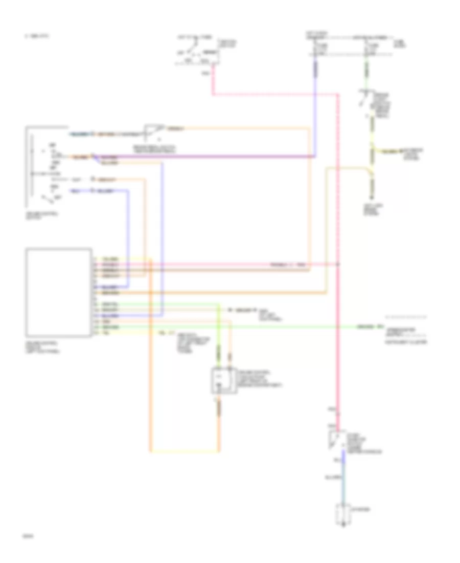
AIR CONDITIONING
2.3L
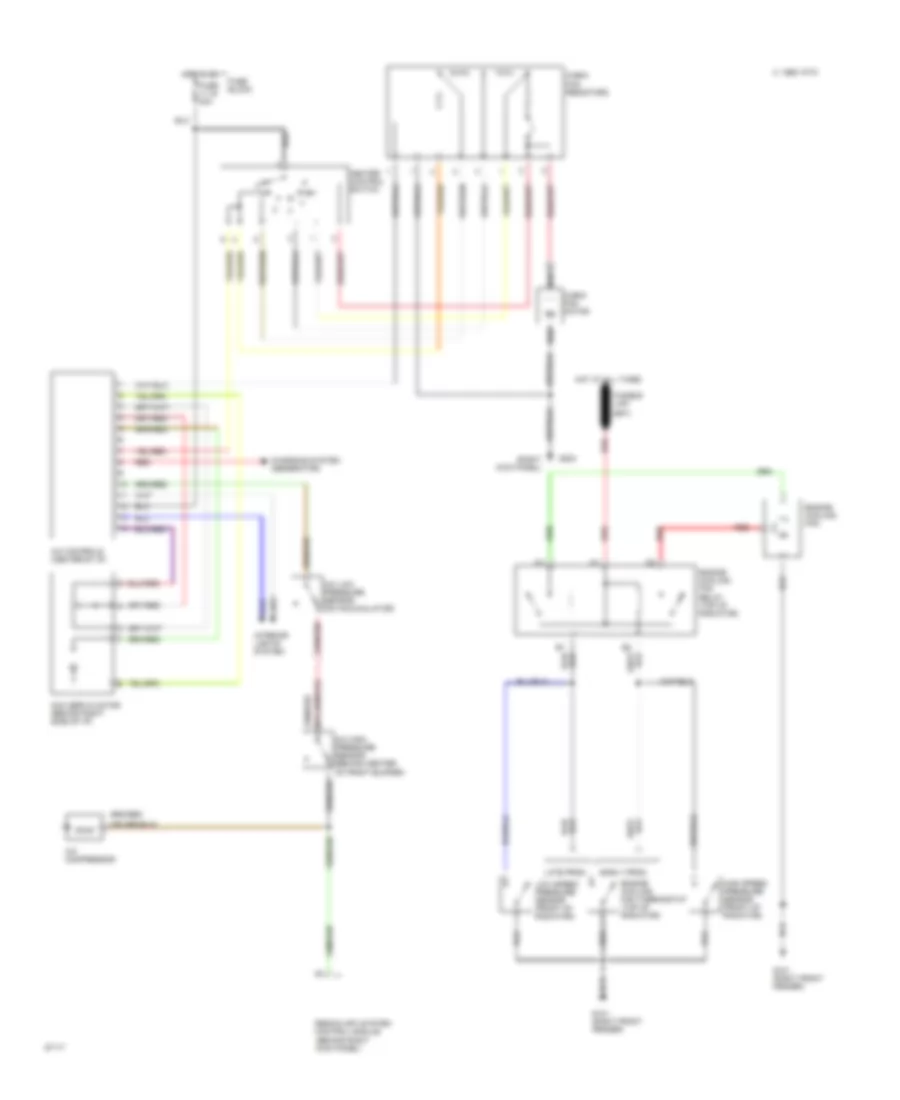
2.3L LH-Jetronic, A/C Wiring Diagram for Volvo 940 1994
 https://portal-diagnostov.com/license.html
Automotive Electricians Portal FZCO
Automotive Electricians Portal FZCO
https://portal-diagnostov.com/license.html
https://portal-diagnostov.com/license.html
Automotive Electricians Portal FZCO
Automotive Electricians Portal FZCO
List of elements for 2.3L LH-Jetronic, A/C Wiring Diagram for Volvo 940 1994:
- (right kick panel)
- A/c compressor
- A/c controls (center of i/p)
- A/c high pressure sensor (behind center
- A/c low pressure sensor (on accumulator)
- C 1995 vftc
- Cabin fan motor
- Cabin fan resistors
- Charging system (generator)
- Engine cooling fan
- Engine cooling fan relay (top of radiator)
- Fuse 11-16 30a
- Fuse block
- Fusible link
- G101 (right front fender)
- G203
- Heater control switch
- High speed pressure sensor (front of radiator)
- Hot at all times
- Hot in on
- Interior lights system
- Lh-jetronic 2.4 (mfi) system control module (behind right kick panel)
- Low speed pressure sensor (front of radiator)
- Mcc servo motor (behind right side of i/p)
- Of front bumper)
- Red
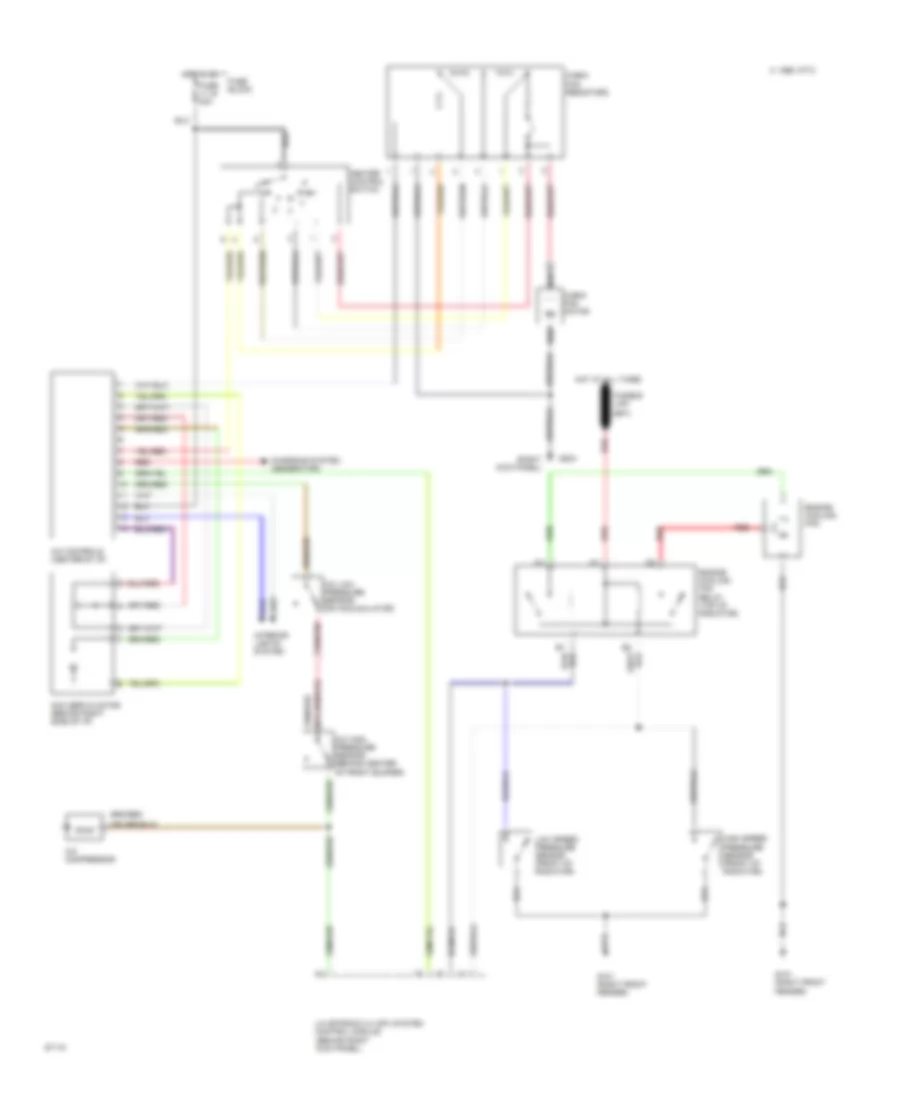
2.3L Regina, Air Conditioning Wiring Diagrams for Volvo 940 1994
List of elements for 2.3L Regina, Air Conditioning Wiring Diagrams for Volvo 940 1994:
- (right kick panel)
- A/c compressor
- A/c controls (center of i/p)
- A/c high pressure sensor (behind center
- A/c low pressure sensor (on accumulator)
- C 1995 vftc
- Cabin fan motor
- Cabin fan resistors
- Charging system (generator)
- Early prod
- Engine cooling fan
- Engine cooling fan relay (top of radiator)
- Engine cooling fan thermostat (top of radiator)
- Fuse 11-16 30a
- Fuse block
- Fusible link
- G101 (right front fender)
- G203
- Heater control switch
- High speed pressure sensor (front of radiator)
- Hot at all times
- Hot in on
- Interior lights system
- Late prod
- Low speed pressure sensor (front of radiator)
- Mcc servo motor (behind right side of i/p)
- Of front bumper)
- Red
- Regina (mfi) system control module (behind right kick panel)
2.3L Turbo, A/C Wiring Diagram for Volvo 940 1994
List of elements for 2.3L Turbo, A/C Wiring Diagram for Volvo 940 1994:
- (right kick panel)
- A/c compressor
- A/c controls (center of i/p)
- A/c high pressure sensor (behind center
- A/c low pressure sensor (on accumulator)
- C 1995 vftc
- Cabin fan motor
- Cabin fan resistors
- Charging system (generator)
- Engine cooling fan
- Engine cooling fan relay (top of radiator)
- Fuse 11-16 30a
- Fuse block
- Fusible link
- G101 (right front fender)
- G203
- Heater control switch
- High speed pressure sensor (front of radiator)
- Hot at all times
- Hot in on
- Interior lights system
- Lh-jetronic 2.4 (mfi) system control module (behind right kick panel)
- Low speed pressure sensor (front of radiator)
- Mcc servo motor (behind right side of i/p)
- Of front bumper)
- Red
ANTI-LOCK BRAKES
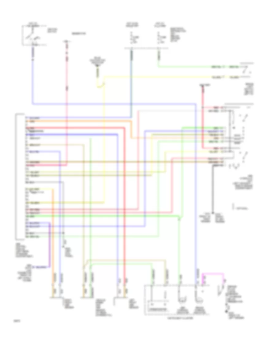
Anti-lock Brake Wiring Diagrams for Volvo 940 1994
List of elements for Anti-lock Brake Wiring Diagrams for Volvo 940 1994:
- * optional
- 15r
- Abs control module (left rear of engine compartment)
- Abs hydraulic unit (left (or right ) side of engine compartment)
- Abs warning indicator
- Battery
- Brake fluid level sensor (on brake fluid reservoir)
- Brake light switch (below left i/p)
- Brake warning indicator
- Bulb malfunction indicator pin 9
- Electrical distribution unit (below center of i/p)
- Fuse 15a
- G100 (front of left fender)
- G101 (front of right fender)
- G200 (left kick panel)
- Generator
- Hot at all times
- Hot in on and start
- Ignition switch
- Iii
- Instrument cluster
- Left front abs sensor
- Nca
- Obd data link connector (front of left strut tower)
- Pnk
- Red
- Right front abs sensor
- Speedometer
- Vehicle speed and abs sensor (at rear differential)
ANTI-THEFT
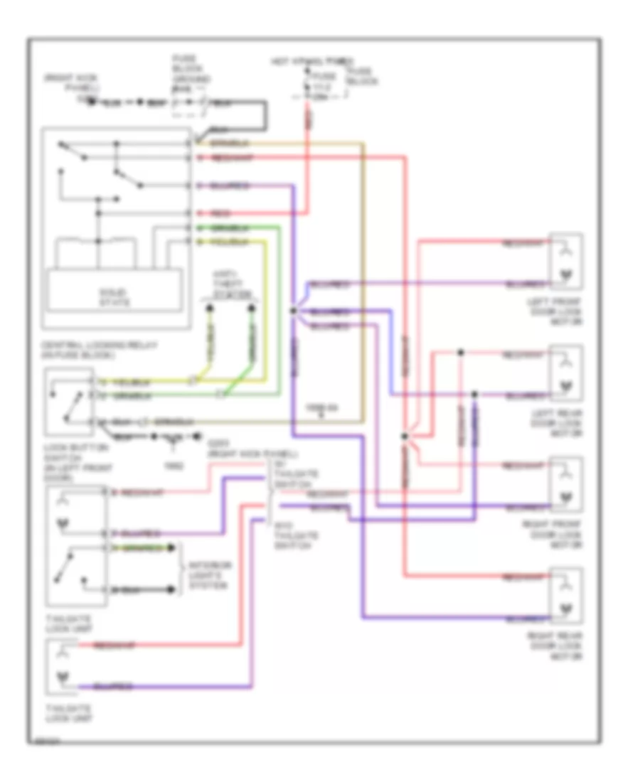
Anti-theft Wiring Diagram for Volvo 940 1994
List of elements for Anti-theft Wiring Diagram for Volvo 940 1994:
- Anti-theft alarm connectors (at steering column)
- C 1995 vftc
- Central lock relay (in relay box)
- Door locks system
- Exterior lights system
- Fuse 11-12 15a
- Fuse 11-2 25a
- Fuse 11-5 15a
- Fuse block
- Fuse block ground rail
- G203 (right kick panel)
- G407 (center rear of trunk) (sedan) case ground (wagon)
- Hot at all times
- Hot in run or start
- Left front door switch
- Left rear door switch
- Lock button switch
- Red
- Right front door switch
- Right rear door switch
- Tailgate lock unit
- Trunk light (sedan) roof light (wagon)
- Voltage rail 15-9
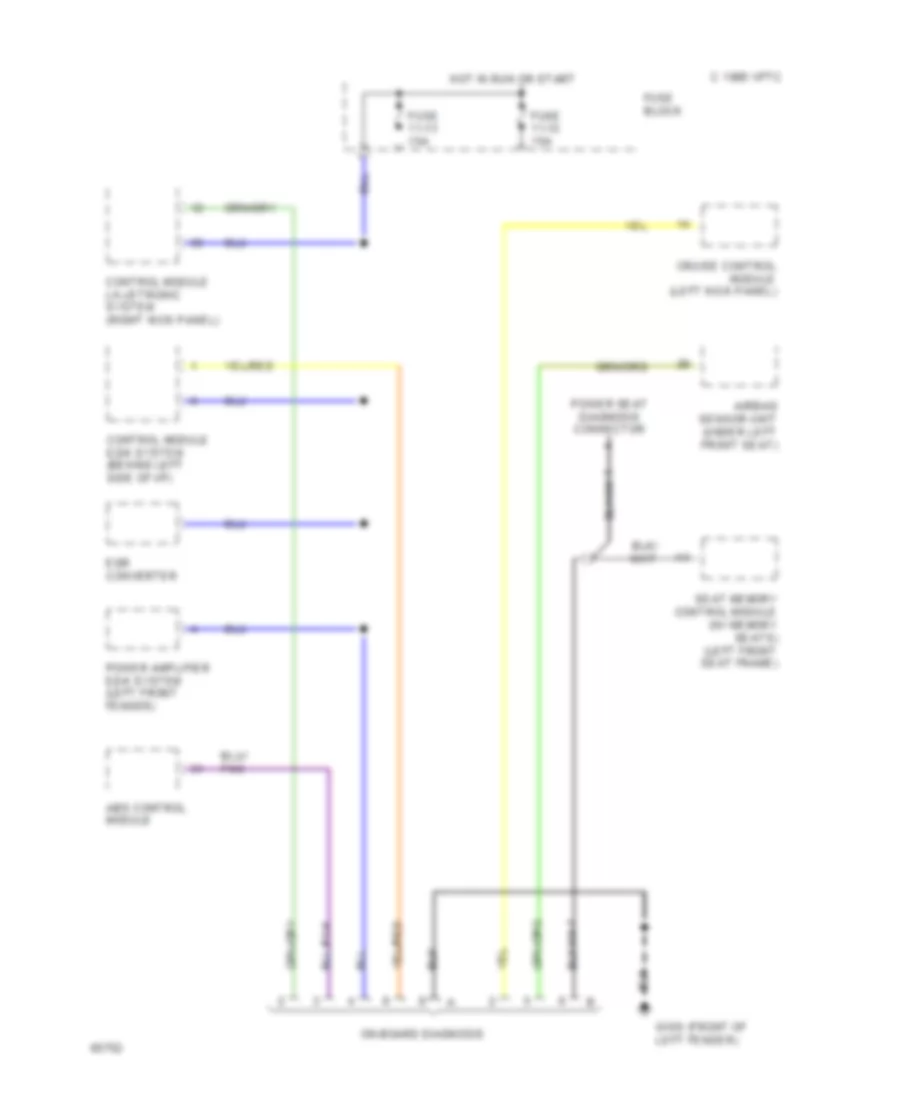
COMPUTER DATA LINES
Computer Data Lines for Volvo 940 1994
List of elements for Computer Data Lines for Volvo 940 1994:
- Abs control module
- Airbag sensor unit (under left front seat)
- C 1995 vftc
- Control module ez-k system (behind left side of i/p)
- Control module lh-jetronic system (right kick panel)
- Cruise control module (left kick panel)
- Egr converter
- Fuse 11-12 15a
- Fuse 11-13 15a
- Fuse block
- G100 (front of
- Hot in run or start
- Left fender)
- On-board diagnosis
- Power amplifier ez-k system (left front fender)
- Power seat diagnosis connector
- Seat memory control module (w/ memory seats) (left front seat frame)
COOLING FAN
2.3L
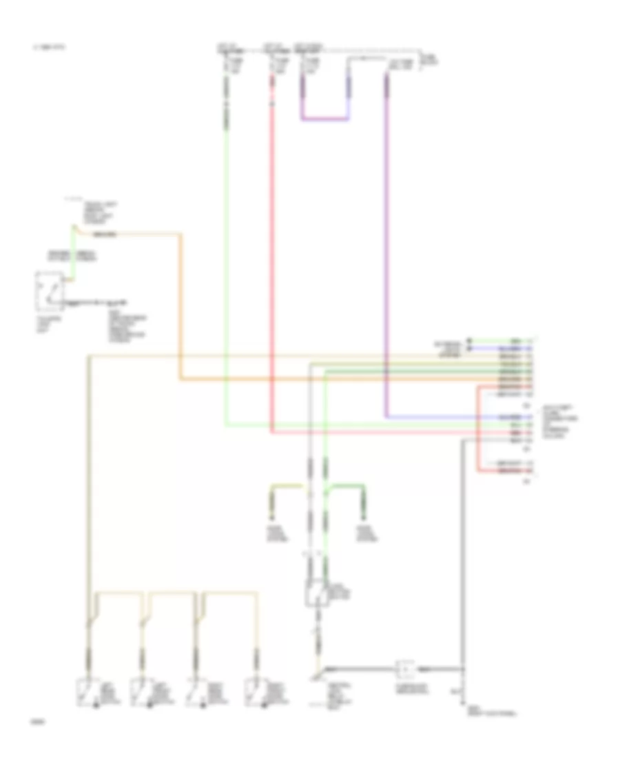
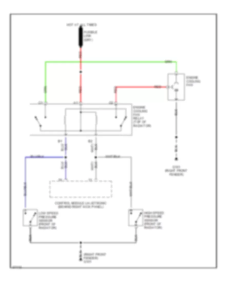
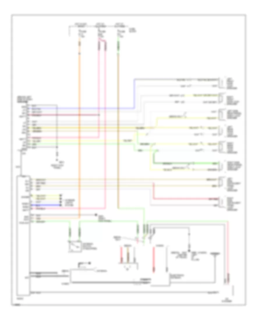
2.3L LH-Jetronic, Cooling Fan Wiring Diagram for Volvo 940 1994
List of elements for 2.3L LH-Jetronic, Cooling Fan Wiring Diagram for Volvo 940 1994:
- (right front fender) g101
- Control module lh-jetronic (behind right kick panel)
- Engine cooling fan
- Engine cooling fan relay (top of radiator)
- Fusible link
- G101 (right front fender)
- High speed pressure sensor (front of radiator)
- Hot at all times
- Low speed pressure sensor (front of radiator)
- Red
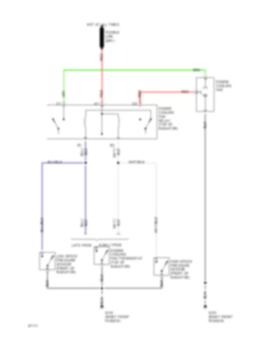
2.3L Regina, Cooling Fan Wiring Diagram for Volvo 940 1994
List of elements for 2.3L Regina, Cooling Fan Wiring Diagram for Volvo 940 1994:
- Early prod
- Engine cooling fan
- Engine cooling fan relay (top of radiator)
- Engine cooling fan thermostat (top of radiator)
- Fusible link
- G101 (right front fender)
- High speed pressure sensor (front of radiator)
- Hot at all times
- Late prod
- Low speed pressure sensor (front of radiator)
- Red
2.3L Turbo, Cooling Fan Wiring Diagram for Volvo 940 1994
List of elements for 2.3L Turbo, Cooling Fan Wiring Diagram for Volvo 940 1994:
- (right front fender) g101
- Control module lh-jetronic (behind right kick panel)
- Engine cooling fan
- Engine cooling fan relay (top of radiator)
- Fusible link
- G101 (right front fender)
- High speed pressure sensor (front of radiator)
- Hot at all times
- Low speed pressure sensor (front of radiator)
- Red
CRUISE CONTROL
Cruise Control Wiring Diagram for Volvo 940 1994
List of elements for Cruise Control Wiring Diagram for Volvo 940 1994:
- Acc
- Anti-lock brake system
- Brake light switch (above brake pedal)
- Brake pedal switch (above brake pedal)
- C 1995 vftc
- Cruise control module (left kick panel)
- Cruise control switch
- Cruise control vacuum pump (left front of engine compartment)
- Exterior lights system
- Fuse 11/12 15a
- Fuse 11/4 15a
- Fuse block
- G200 (at left kick panel)
- Hot at all times
- Hot in run
- Ignition switch
- Instrument cluster
- Obd data link connector (at left front shock tower)
- Off
- Or start
- Pnk
- Res
- Run
- Set
- Speedometer output
- Start
- Start inhibitor switch (under center console)
- Starter
DEFOGGERS
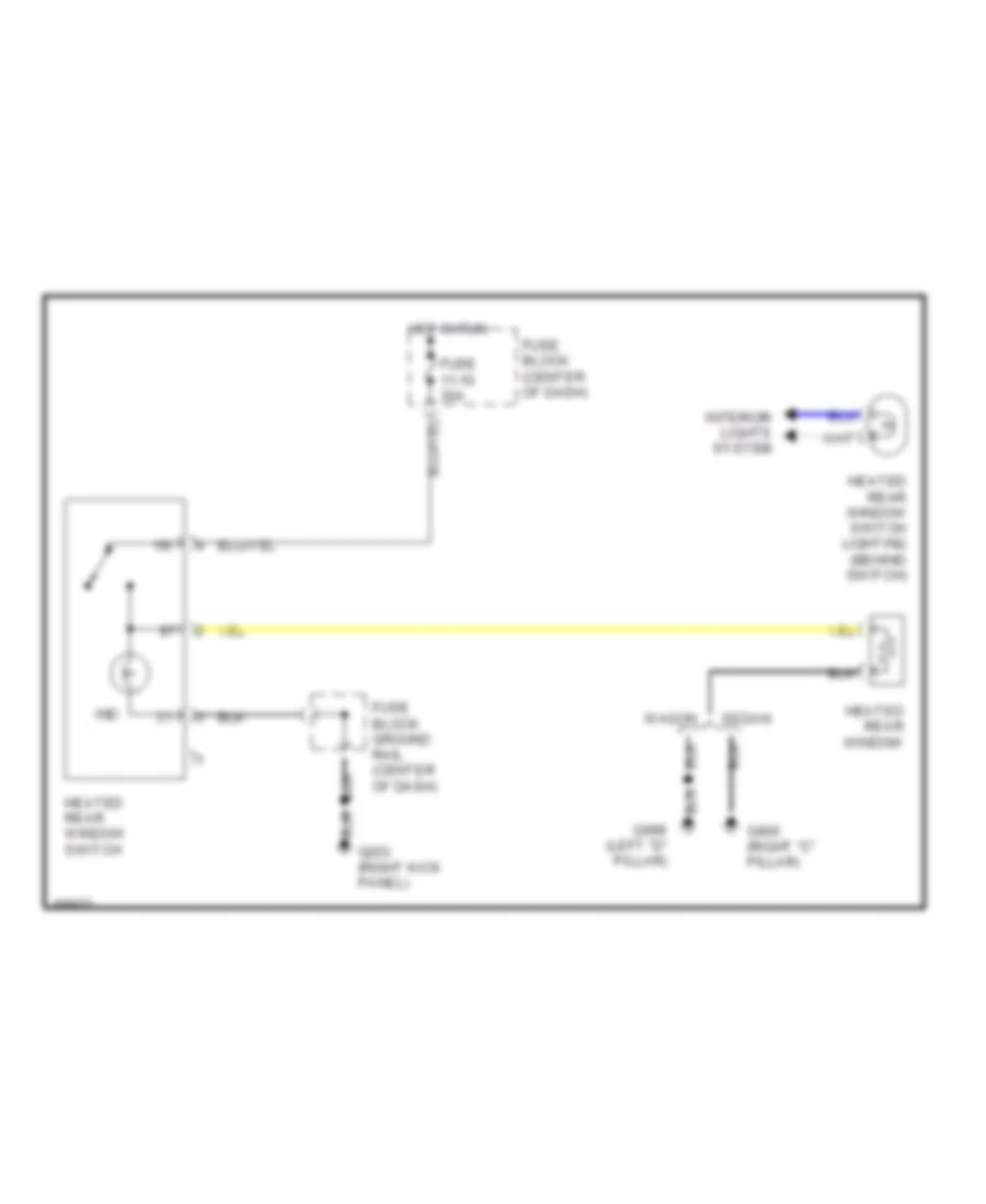
Defogger Wiring Diagram for Volvo 940 1994
List of elements for Defogger Wiring Diagram for Volvo 940 1994:
- 15i
- Fuse 11-10 30a
- Fuse block (center of dash)
- Fuse block ground rail (center of dash)
- G203 (right kick panel)
- G905 (right "c" pillar)
- G999 (left "d" pillar)
- Heated rear window
- Heated rear window switch
- Heated rear window switch lighting (behind switch)
- Hot in run
- Ind
- Interior lights system
- Sedan
- Wagon
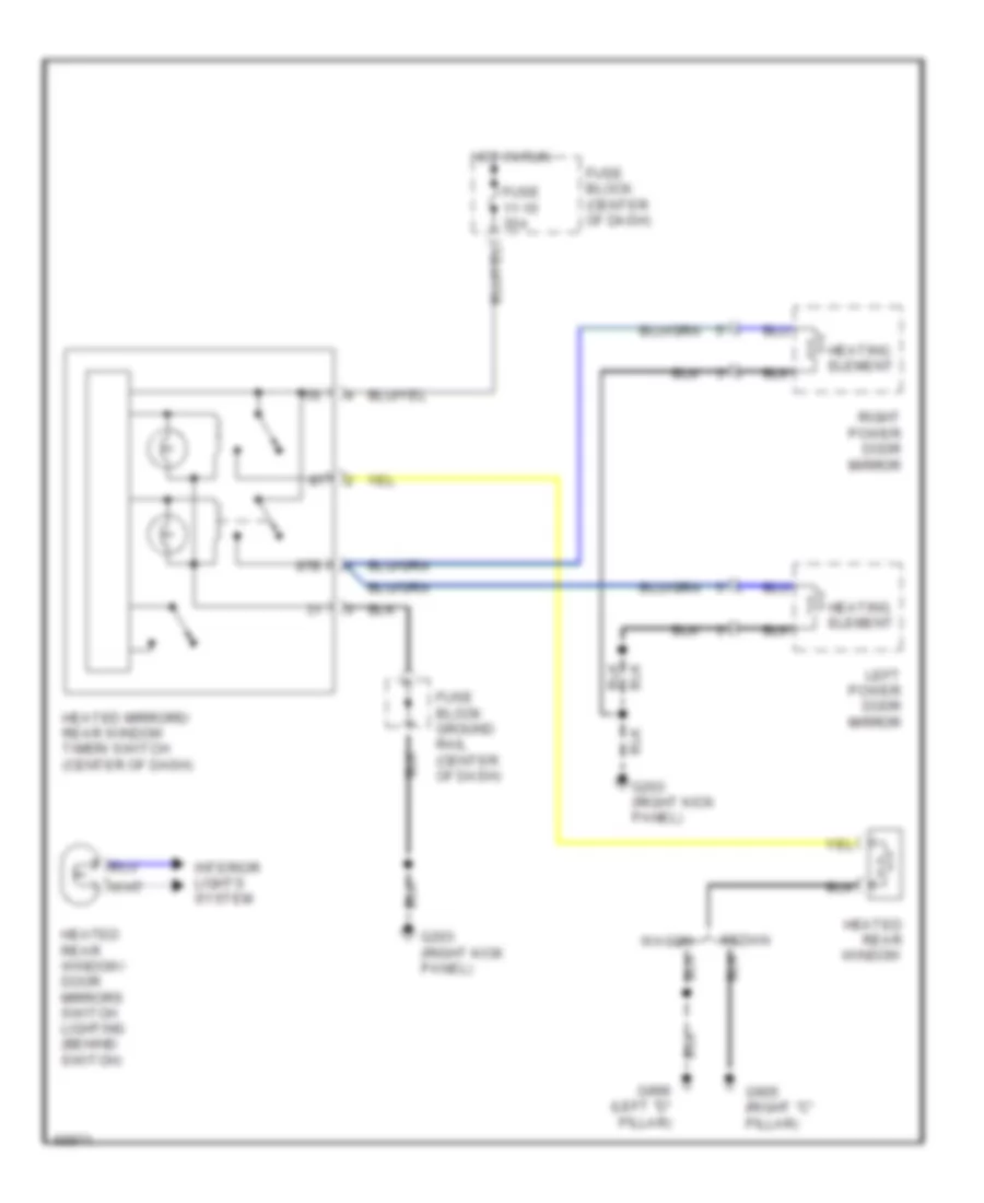
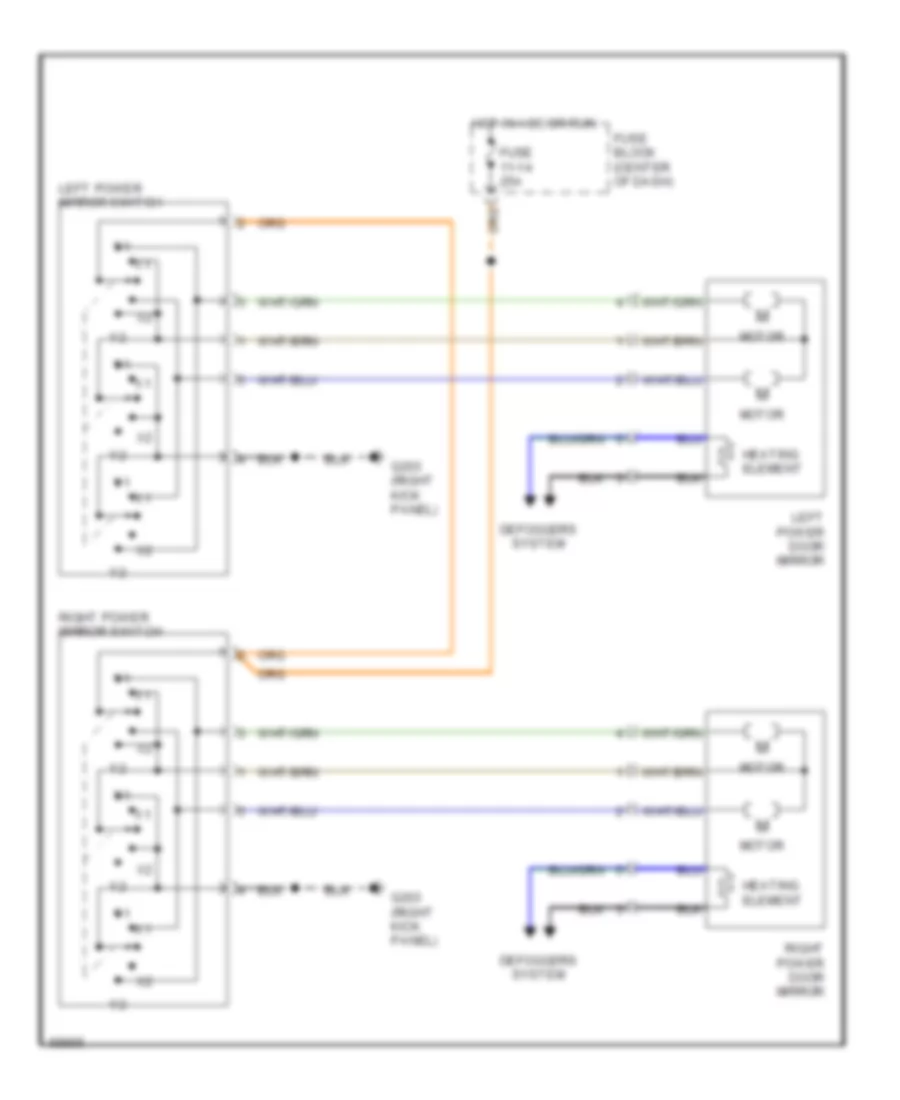
Rear Defogger & Heated Mirrors Wiring Diagram for Volvo 940 1994
List of elements for Rear Defogger & Heated Mirrors Wiring Diagram for Volvo 940 1994:
- 15i
- 87b
- Fuse 11-10 30a
- Fuse block (center of dash)
- Fuse block ground rail (center of dash)
- G203 (right kick panel)
- G905 (right "c" pillar)
- G999 (left "d" pillar)
- Heated mirrors/ rear window timer/ switch (center of dash)
- Heated rear window
- Heated rear window/ door mirrors switch lighting (behind switch)
- Heating element
- Hot in run
- Interior lights system
- Left power door mirror
- Right power door mirror
- Sedan
- Wagon
ENGINE PERFORMANCE
2.3L
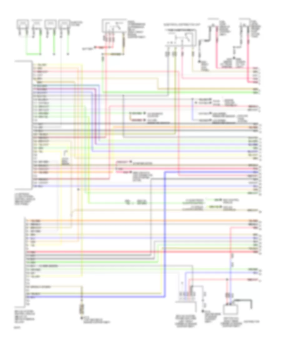
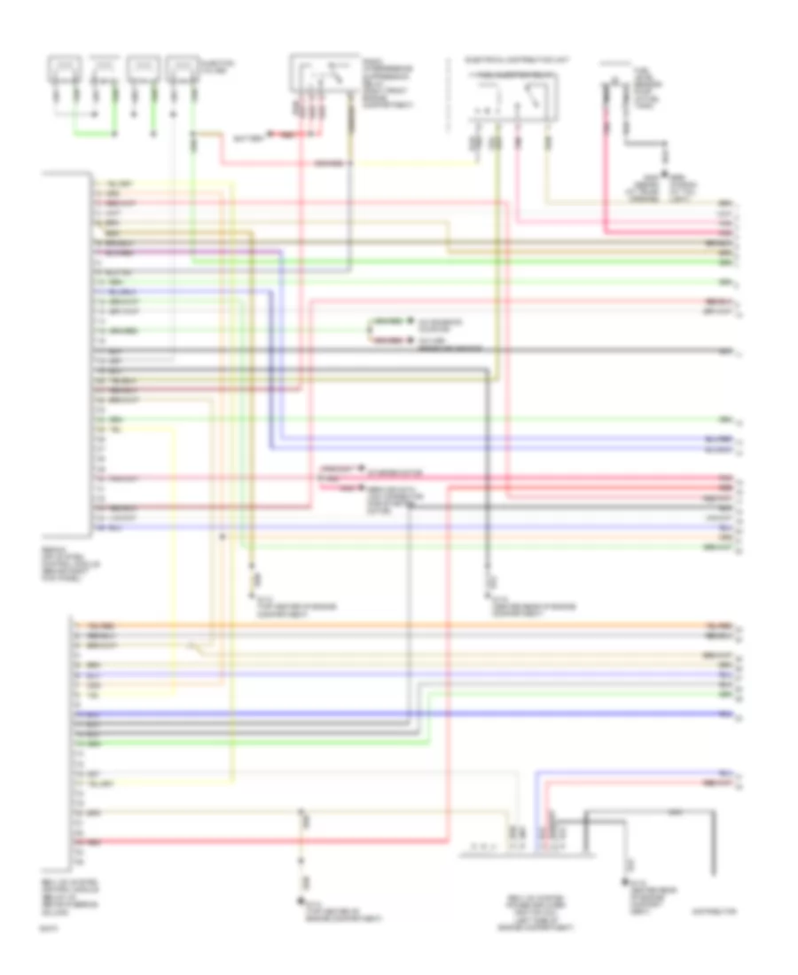
2.3L LH-Jetronic, Engine Performance Wiring Diagrams (1 of 2) for Volvo 940 1994
List of elements for 2.3L LH-Jetronic, Engine Performance Wiring Diagrams (1 of 2) for Volvo 940 1994:
-
- (below i/p, above steering column)
- (w/ egr, b230fd)
- (with b200/ b230g)
- A/c high pressure sensor
- A/c solenoid coupling
- Battery
- Bus
- Cooling fans system
- Distributor
- Ecc control module
- Electrical distribution unit
- Engine cooling fan relay
- Ez-k (di) system control module
- Ez-k (di) system power amplifier (left front corner of engine compartment)
- Fuel injection relay
- Fuel level sensor/ primer
- Fuel pump (rear of engine compart- ment)
- G112 (top center of engine compartment)
- G115 center rear of engine compart- ment)
- G203 (right kick panel)
- G408 (sedan) (at trunk opening)
- G999 (wagon) (at tail light)
- High-speed pressure sensor
- Ignition coil (right rear corner of engine compartment)
- Injection valves
- Lh-jetronic 2.4 (mfi) system control module (behind right kick panel)
- Low-speed pressure sensor
- Mcc a/c controls
- Nca
- Pin b1
- Pin b2
- Pnk
- Pump (in fuel tank)
- Radio interference suppression relay (right front engine compartment)
- Red
- Red/
- Service data link connector (for starter motor)
- Starter motor
- W/ electronic climate control
- W/ manual climate control
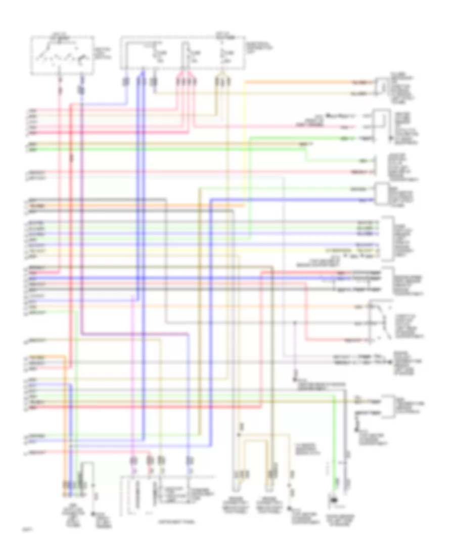
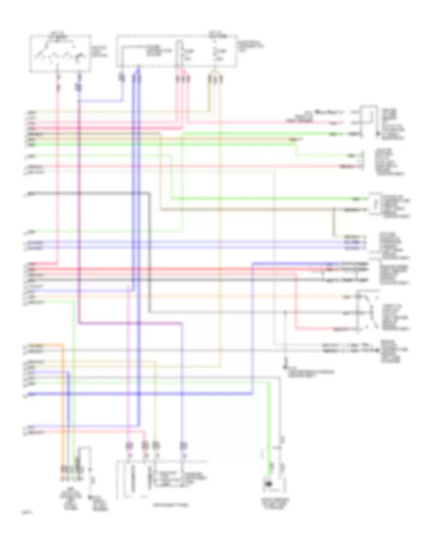
2.3L LH-Jetronic, Engine Performance Wiring Diagrams (2 of 2) for Volvo 940 1994
List of elements for 2.3L LH-Jetronic, Engine Performance Wiring Diagrams (2 of 2) for Volvo 940 1994:
- (behind right kick panel)
- (w/ b200/230g)
- * w/ b200fg, b230f/fb/g, b230fd auto
- 15r
- Bridge connector 1
- Bridge connector 2
- Combined instrument fuse
- Egr convertor (california) (left strut tower)
- Egr temperature sensor (california)
- Electrical distribution unit
- Engine coolant temperature sensor (left side of engine)
- Engine speed (rpm) sensor (rear of engine compartment)
- Fuse 15a
- Fuse 25a
- G100 (front of left fender)
- G101 (front of right fender)
- G112 (top center of engine compartment)
- G115 (center rear of engine compartment)
- Heated oxygen sensor (at catalytic convertor) (w/ b200f, b230f/fb/fd)
- Hot at all times
- Idle air control valve (top left center of engine compartment)
- Ignition lock (switch)
- Iii
- Instrument panel
- Knock sensor (on left side of engine)
- Malfunc- tion indicator lamp
- Mass air flow sensor (left side of engine compart- ment)
- Nca
- Obd data link connector (left strut tower)
- Pnk
- Pulsed secondary air injection solenoid (w/ b230fd) (left strut tower)
- Red
- Speedometer
- Tachometer
- Throttle position switch (left rear of engine compartment)
2.3L Regina, Engine Performance Wiring Diagrams (1 of 2) for Volvo 940 1994
List of elements for 2.3L Regina, Engine Performance Wiring Diagrams (1 of 2) for Volvo 940 1994:
-
- (below i/p, above steering column)
- (left side of engine compartment)
- A/c high pressure sensor
- A/c solenoid coupling
- Battery
- Distributor
- Electrical distribution unit
- Fuel injection relay
- Fuel level sensor/ pump (in fuel tank)
- G112 (top center of engine compartment)
- G115 center rear of engine compart- ment)
- G408 (sedan) (at trunk opening)
- G999 (wagon) (at tail light)
- Injection valves
- Nca
- Pnk
- Radio interference suppression relay (right front engine compartment)
- Red
- Red/
- Regina (mfi) system control module (behind right kick panel)
- Rex-i (di) system control module
- Rex-i (di) system power amplifier/ ignition coil
- Service data link connector (for starter motor)
- Starter motor
2.3L Regina, Engine Performance Wiring Diagrams (2 of 2) for Volvo 940 1994
List of elements for 2.3L Regina, Engine Performance Wiring Diagrams (2 of 2) for Volvo 940 1994:
- 15r
- Combined instrument fuse
- Electrical distribution unit
- Engine coolant temperature sensor (left side of engine)
- Engine speed (rpm) sensor (rear of engine compartment)
- Fuse 15a
- Fuse 25a
- G100 (front of left fender)
- G101 (front of right fender)
- G115 (center rear of engine compartment)
- Heated oxygen sensor (at catalytic convertor) (w/ b200f, b230f/fb/fd)
- Hot at all times
- Idle air control valve (top left center of engine compartment)
- Ignition lock (switch)
- Iii
- Instrument panel
- Intake air temperature sensor (left front engine compartment)
- Intake manifold pressure sensor (left rear engine compartment)
- Knock sensor (on left side of engine)
- Malfunc- tion indicator lamp
- Nca
- Obd data link connector (left strut tower)
- Pnk
- Power distribution system
- Red
- Speedometer
- Tachometer
- Throttle position switch (left center rear of engine compartment)
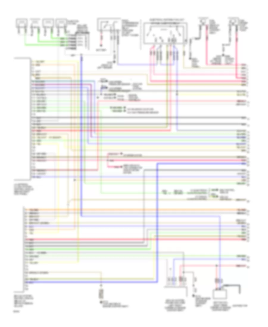
2.3L Turbo, Engine Performance Wiring Diagrams (1 of 2) for Volvo 940 1994
List of elements for 2.3L Turbo, Engine Performance Wiring Diagrams (1 of 2) for Volvo 940 1994:
- (below i/p, above steering column)
- (w/ b230gt)
- (w/ egr)
- 86/1
- 86/2
- 87/1
- 87/2
- A/c high pressure sensor
- A/c solenoid coupling
- Ballast resistor (front of left fender)
- Battery
- Bus
- Cooling fans system
- Distributor
- Ecc control module
- Electrical distribution unit
- Engine cooling fan relay
- Ez-k (di) system control module
- Ez-k (di) system power amplifier (left front corner of engine compartment)
- Fuel primer pump (in fuel tank)
- Fuel pump (rear of engine compart- ment)
- G100 (front of left fender)
- G112 (top center of engine compartment)
- G115 center rear of engine compart- ment)
- G203 (right kick panel)
- G408 (sedan) (at trunk opening)
- G999 (wagon) (at tail light)
- High-speed pressure sensor
- Ignition coil (right rear corner of engine compartment)
- Injection valves
- Lh-jetronic 2.4 (mfi) system control module (behind right kick panel)
- Low-speed pressure sensor
- Mcc a/c controls
- Mfi fuel injection relay
- Nca
- Pin b1
- Pin b2
- Pnk
- Radio interference suppression relay (forward of left strut tower)
- Red
- Service data link connector (for starter motor)
- Starter motor
- W/ electronic climate control
- W/ manual climate control
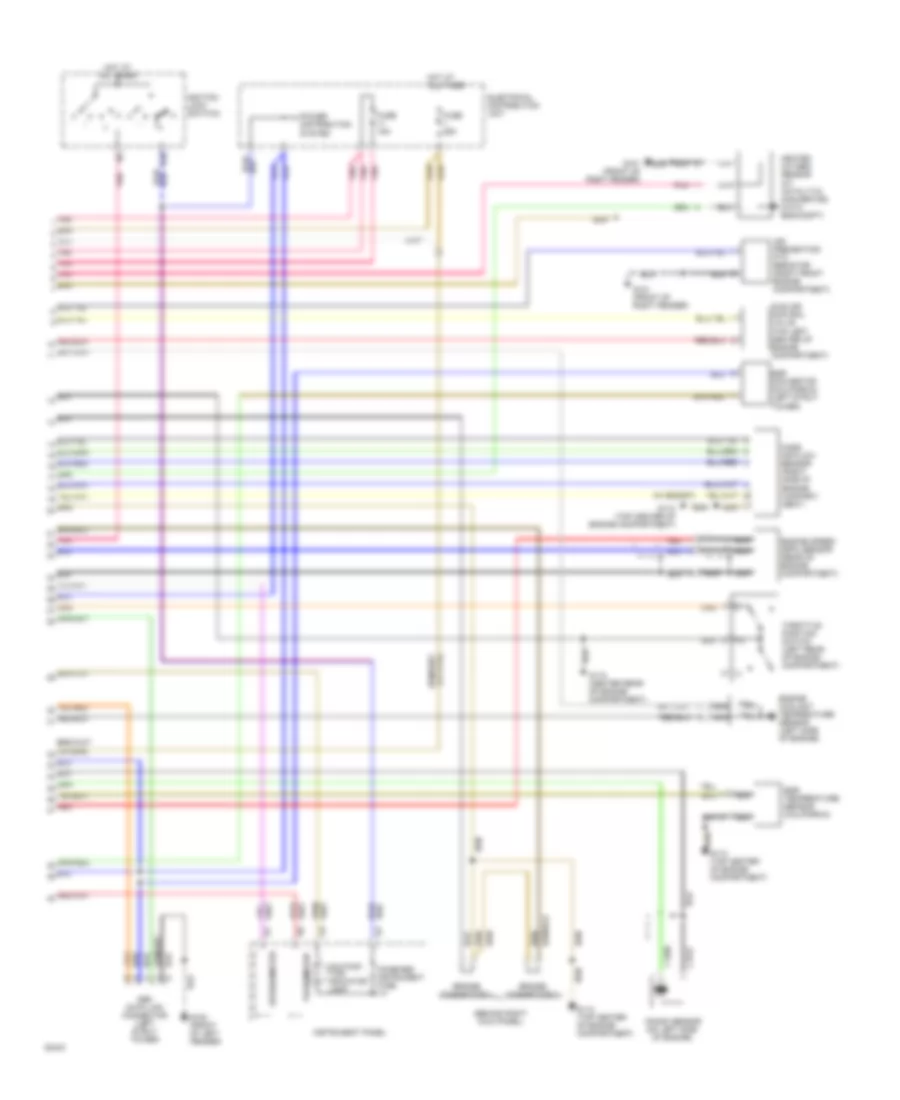
2.3L Turbo, Engine Performance Wiring Diagrams (2 of 2) for Volvo 940 1994
List of elements for 2.3L Turbo, Engine Performance Wiring Diagrams (2 of 2) for Volvo 940 1994:
- (behind right kick panel)
- (w/ b230gt)
- 15r
- Air preheating ptc resistor (right front engine compartment)
- Bridge connector 1
- Bridge connector 2
- Combined instrument fuse
- Egr convertor (california) (left strut tower)
- Egr temperature sensor (california)
- Electrical distribution unit
- Engine coolant temperature sensor (left side of engine)
- Engine speed (rpm) sensor (rear of engine compartment)
- Fuse 15a
- Fuse 25a
- G100 (front of left fender)
- G101 (front of right fender)
- G112 (top center of engine compartment)
- G115 (center rear of engine compartment)
- Heated oxygen sensor (at catalytic convertor) (with b200/230ft)
- Hot at all times
- Idle air control valve (top left center of engine compartment)
- Ignition lock (switch)
- Iii
- Instrument panel
- Knock sensor (on left side of engine)
- Malfunc- tion indicator lamp
- Mass air flow sensor (right side of engine compart- ment)
- Nca
- Obd data link connector (left strut tower)
- Pnk
- Power distribution system
- Red
- Speedometer
- Tachometer
- Throttle position switch (left rear of engine compartment)
EXTERIOR LIGHTS
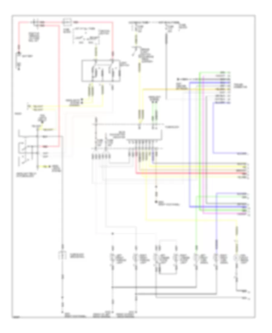
Exterior Lamps Wiring Diagram, Sedan (1 of 2) for Volvo 940 1994
List of elements for Exterior Lamps Wiring Diagram, Sedan (1 of 2) for Volvo 940 1994:
- Acc
- Battery
- Brake light switch (on brake pedal support)
- Bulb malfunction indicator
- Fog lights circuit
- Fuse 11-21 15a
- Fuse 11-22 15a
- Fuse 11-3 30a
- Fuse 11-4 15a
- Fuse block
- Fuse block ground rail
- G100 (front of left front fender)
- G101 (front of right front fender)
- G203 (right kick panel)
- G407 (center of trunk)
- Head
- Head- lights system
- Headlight
- Headlight relay (in fuse block)
- Headlights system (canada)
- High mount brake light
- Hot at all times
- Ignition switch
- Left front parking light
- Left front turn signal
- Left license plate light
- Light switch
- Lock
- Off
- Park
- Positive terminal voltage rail 15-1
- Radio
- Red
- Right front parking light
- Right front turn signal
- Right license plate light
- Run
- Start
- System
- Trailer connector
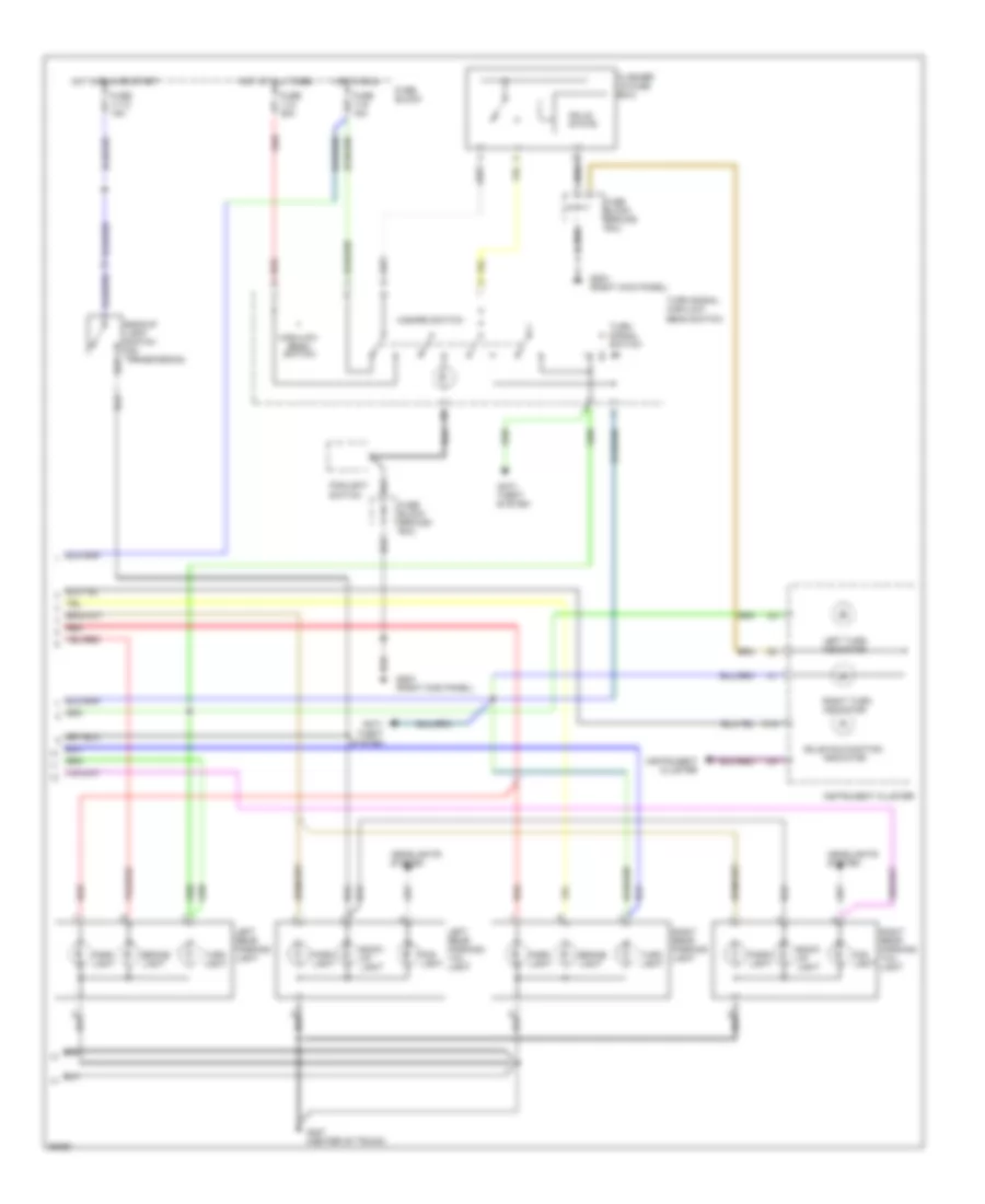
Exterior Lamps Wiring Diagram, Sedan (2 of 2) for Volvo 940 1994
List of elements for Exterior Lamps Wiring Diagram, Sedan (2 of 2) for Volvo 940 1994:
- Anti- theft system
- Back- up light
- Backup light switch (on transmission)
- Beam switch
- Brake light
- Bulb malfunction
- C15
- Flasher (in fuse box)
- Fog light
- Foglight switch
- Fuse 11-12 15a
- Fuse 11-2 25a
- Fuse 11-9 15a
- Fuse block
- Fuse block ground rail
- G203 (right kick panel)
- G407 (center of trunk)
- Hazard switch
- Headlights system
- High/low
- Hot at all times
- Hot in run
- Hot in run or start
- Indicator
- Instrument cluster
- Left rear parking light
- Left rear parking/ tail light
- Left turn indicator
- Park light
- Red
- Right rear parking light
- Right rear parking/ tail light
- Right turn indicator
- Solid state
- Turn light
- Turn signal high/low beam switch
- Turn signal switch
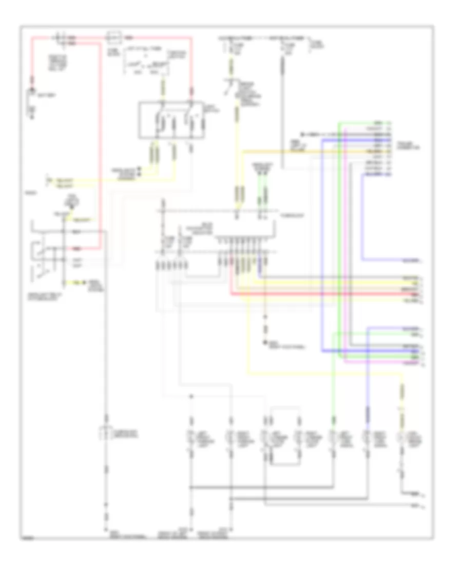
Exterior Lamps Wiring Diagram, Wagon (1 of 2) for Volvo 940 1994
List of elements for Exterior Lamps Wiring Diagram, Wagon (1 of 2) for Volvo 940 1994:
- Acc
- Battery
- Brake light switch (on brake pedal support)
- Bulb malfunction indicator
- Fog lights circuit
- Fuse 11-21 15a
- Fuse 11-22 15a
- Fuse 11-3 30a
- Fuse 11-4 15a
- Fuse block
- Fuse block ground rail
- G100 (front of left front fender)
- G101 (front of right front fender)
- G203 (right kick panel)
- G999 (left "d" pillar)
- Head
- Head- lights system
- Headlight
- Headlight relay (in fuse block)
- Headlights system (canada)
- High mount brake light
- Hot at all times
- Ignition switch
- Left front parking light
- Left front turn signal
- Left license plate light
- Light switch
- Lock
- Off
- Park
- Positive terminal voltage rail 15-1
- Radio
- Red
- Right front parking light
- Right front turn signal
- Right license plate light
- Run
- Start
- System
- Trailer connector
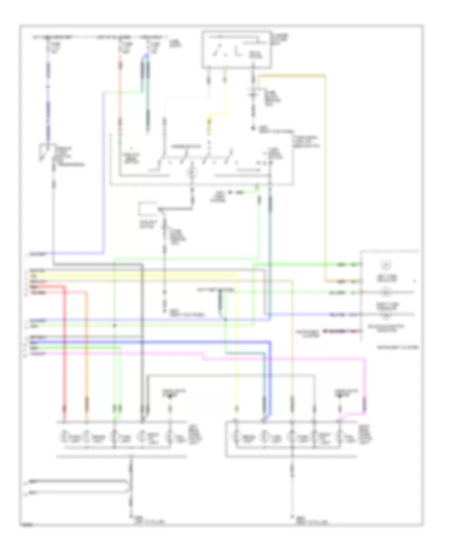
Exterior Lamps Wiring Diagram, Wagon (2 of 2) for Volvo 940 1994
List of elements for Exterior Lamps Wiring Diagram, Wagon (2 of 2) for Volvo 940 1994:
- Anti- theft system
- Anti-theft system
- Back- up light
- Backup light switch (on transmission)
- Beam switch
- Brake light
- Bulb malfunction
- C15
- Flasher (in fuse box)
- Fog light
- Foglight switch
- Fuse 11-12 15a
- Fuse 11-2 25a
- Fuse 11-9 15a
- Fuse block
- Fuse block ground rail
- G203 (right kick panel)
- G998 (left "d" pillar)
- G999 (right "d" pillar)
- Hazard switch
- Headlights system
- High/low
- Hot at all times
- Hot in run
- Hot in run or start
- Indicator
- Instrument cluster
- Left rear combi- nation light
- Left turn indicator
- Park light
- Red
- Right rear combi- nation light
- Right turn indicator
- Solid state
- Turn light
- Turn signal high/low beam switch
- Turn signal switch
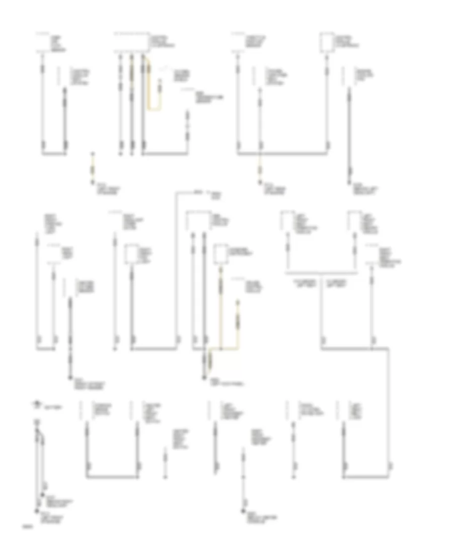
GROUND DISTRIBUTION
Ground Distribution Wiring Diagram (1 of 3) for Volvo 940 1994
List of elements for Ground Distribution Wiring Diagram (1 of 3) for Volvo 940 1994:
- Abs control module
- Battery
- Combined instrument
- Control module ez-k system
- Control module lh-jetronic
- Cruise control module
- Egr temperature sensor
- Engine cooling fan
- From a g100
- G101 (front of right front fender)
- G106 (behind left headlight)
- G107 (behind right headlamp)
- G110 (left front of engine)
- G114 (left rear of engine)
- G200 (left kick panel)
- G302 (below center console)
- Heated left front seat switch
- Heated oxygen sensor
- Heated right front seat switch
- Left front backrest heater
- Left front seat memory module
- Left front seat operating module
- Left seat belt lock
- Mass air- flow sensor
- Nca
- Oxygen sensor shield
- Parking brake switch
- Power amplifier ez-k system
- Radio (w/ integ- rated amp)
- Right front backrest heater
- Right front fog light
- Right front parking/ turn light
- Right front seat operating module
- Right head- light
- Right headlight wiper motor
- Throttle position sensor
- W/ memory left seat
- W/o memory left seat
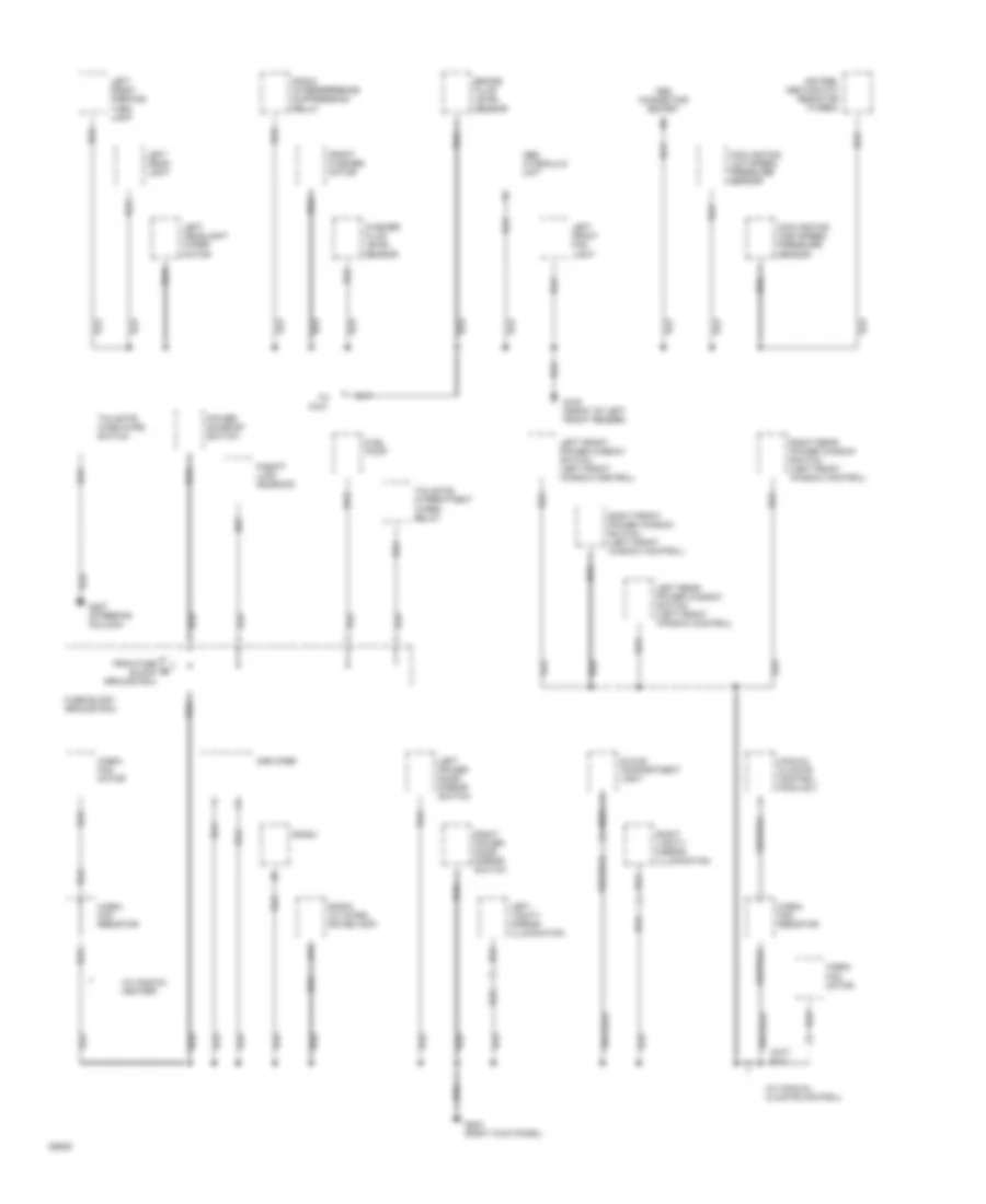
Ground Distribution Wiring Diagram (2 of 3) for Volvo 940 1994
List of elements for Ground Distribution Wiring Diagram (2 of 3) for Volvo 940 1994:
- (w/ manual climate control)
- (w/ manual heater)
- A14
- Abs hydraulic unit
- Air pre- heating ptc resistor (turbo)
- Amplifier
- Brake fluid level sensor
- Cabin fan motor
- Cabin fan resistor
- Cooling fan high speed pressure sensor
- Cooling fan low speed pressure sensor
- From fuse block ground rail
- Front washer motor
- Fuel pump
- Fuse block ground rail
- G100 (front of left front fender)
- G203 (right kick panel)
- G207 (steering column)
- Glove compartment light
- Left front fog light
- Left front parking/ turn light
- Left front power window switch (left front window control)
- Left head- light
- Left headlight wiper motor
- Left power door mirror switch
- Left rear power window switch (left front window control)
- Left vanity mirror illumination
- Manual climate control module 2
- Obd connector socket
- P-shift lock solenoid
- Power sunroof switch
- Radio
- Radio (w/ integ- rated amp)
- Radio interferrence suppression relay
- Right front power window switch (left front window control)
- Right power door mirror switch
- Right rear power window switch (left front window control)
- Right vanity mirror illumination
- Tailgate intermittent wiper relay
- Tailgate wash/wipe switch
- To g101
- Washer fluid level sensor
Ground Distribution Wiring Diagram (3 of 3) for Volvo 940 1994
List of elements for Ground Distribution Wiring Diagram (3 of 3) for Volvo 940 1994:
- Alarm connector
- Bulb malfunction indicator
- Bypass relay 15i
- Cd changer
- Central locking relay
- Cigar lighter
- Combined instrument
- Electronic antenna
- Foglight switch
- Fuel level sensor/primer pump unit
- Fuse block ground rail
- G407 (center of trunk)
- G905 (right 'c' pillar)
- G998 (right 'd' pillar)
- G999 (left 'd' pillar)
- Headlight relay
- Heated rear window
- Heated rear window switch
- High mount brake light
- Left license light
- Left rear brake/ turn light
- Left rear combination light (wagon)
- Left rear parking light
- Load area roof light
- Overdrive relay
- Power antenna
- Right license light
- Right rear brake/ turn light
- Right rear combination light (wagon)
- Right rear parking light
- Roof light
- Seat belt/ key warning relay
- Sedan only
- Tailgate wiper motor
- To fuse block ground rail
- Trunk latch switch
- Turn signal/ high/low beam switch
- Wagon only
- Windshield intermittent wiper relay
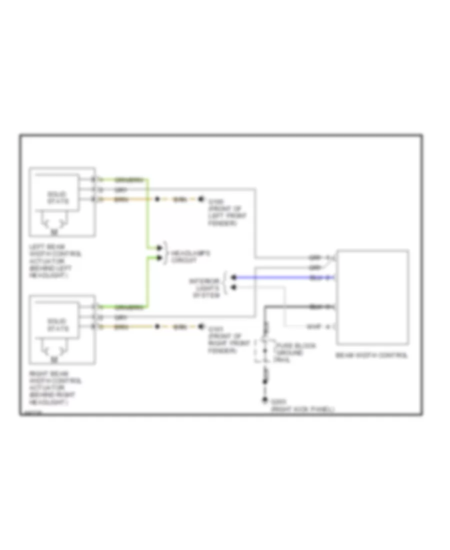
HEADLIGHTS
Beam Width Control for Volvo 940 1994
List of elements for Beam Width Control for Volvo 940 1994:
- Beam width control
- Fuse block ground rail
- G100 (front of left front fender)
- G101 (front of right front fender)
- G203 (right kick panel)
- Headlamps circuit
- Interior lights system
- Left beam width control actuator (behind left headlight)
- Right beam width control actuator (behind right headlight)
- Solid state
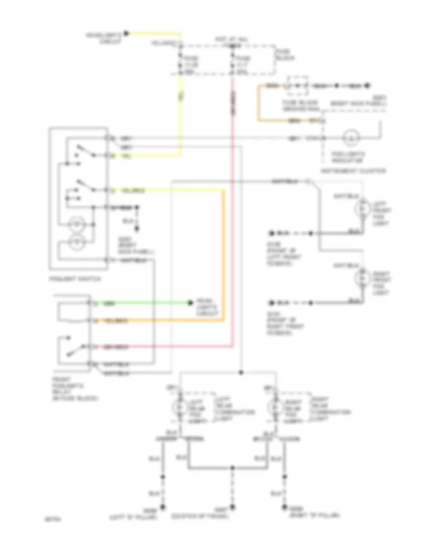
Fog Lamp Wiring Diagram for Volvo 940 1994
List of elements for Fog Lamp Wiring Diagram for Volvo 940 1994:
- C14
- Fog lights indicator
- Foglight switch
- Front foglights relay (in fuse block)
- Fuse 11-25 25a
- Fuse 11-7 15a
- Fuse block
- Fuse block ground rail
- G100 (front of left front fender)
- G101 (front of right front fender)
- G203 (right kick panel)
- G407 (center of trunk)
- G998 (right "d" pillar)
- G999 (left "d" pillar)
- Head- lights circuit
- Headlights circuit
- Hot at all
- Instrument cluster
- Left front fog light
- Left rear combination light
- Left rear fog light
- Right front fog light
- Right rear combination light
- Right rear fog light
- Sedan
- Times
- Wagon
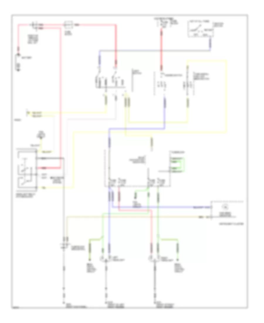
Headlamps Wiring Diagram, with DRL for Volvo 940 1994
List of elements for Headlamps Wiring Diagram, with DRL for Volvo 940 1994:
- Acc
- Battery
- Beam width control circuit
- Bulb malfunction indicator
- C18
- Exterior lights system
- Fog lights circuit
- Ftp
- Fuse 11-17 15a
- Fuse 11-18 15a
- Fuse 11-19 15a
- Fuse 11-2 25a
- Fuse 11-20 15a
- Fuse block
- Fuse block ground rail
- G100 (front of left front fender)
- G101 (front of right front fender)
- G203 (right kick panel)
- Hazard switch
- Head
- Headlight relay (in fuse block)
- High beam indicator
- Hot at all times
- Ignition switch
- Instrument cluster
- Left headlight
- Light switch
- Lock
- Off
- Park
- Positive terminal voltage rail 15-1
- Radio
- Red
- Right headlight
- Run
- Start
- Turn signal/ high low beam switch
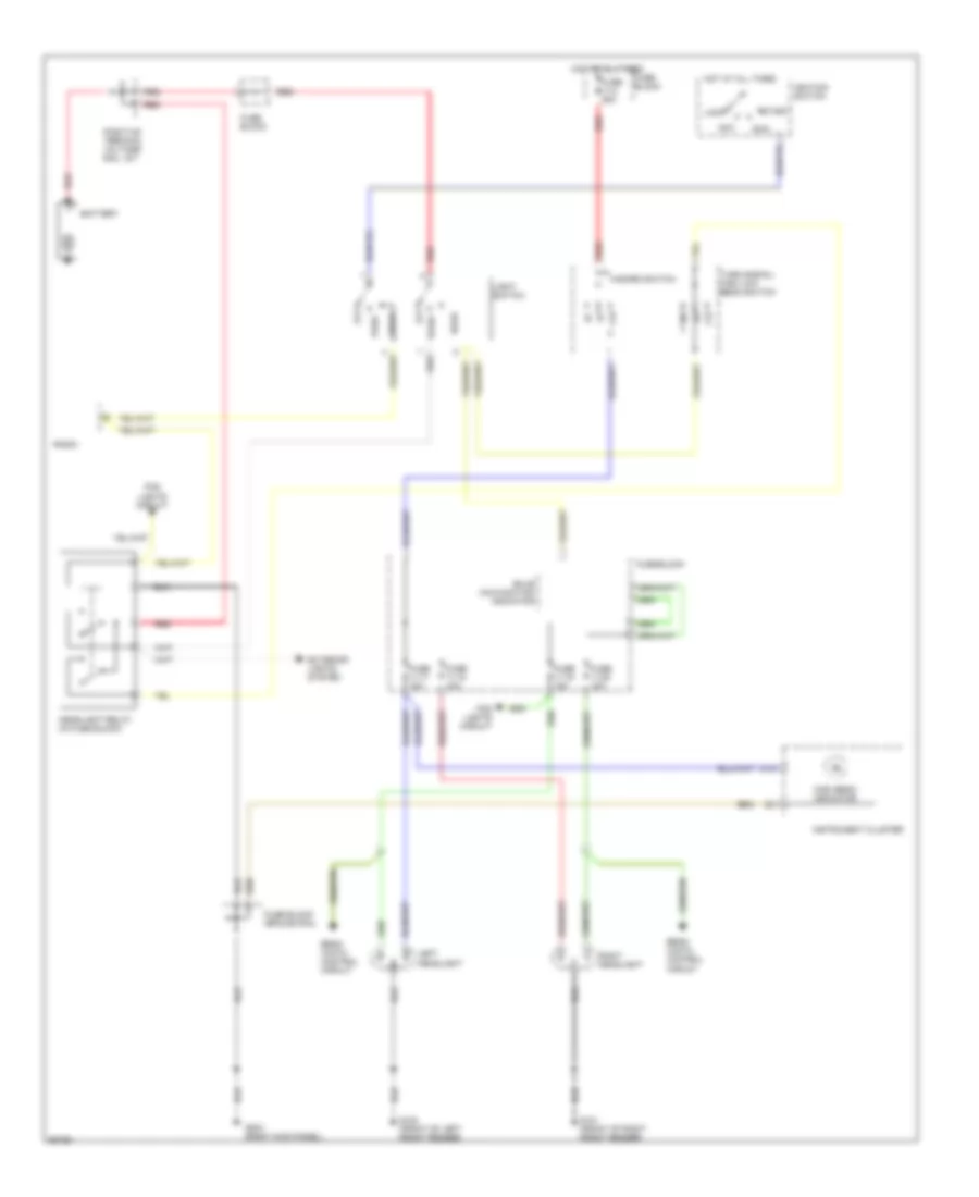
Headlamps Wiring Diagram, without DRL for Volvo 940 1994
List of elements for Headlamps Wiring Diagram, without DRL for Volvo 940 1994:
- Acc
- Battery
- Beam width control circuit
- Bulb malfunction indicator
- C18
- Exterior lights system
- Fog lights circuit
- Ftp
- Fuse 11-17 15a
- Fuse 11-18 15a
- Fuse 11-19 15a
- Fuse 11-2 25a
- Fuse 11-20 15a
- Fuse block
- Fuse block ground rail
- G100 (front of left front fender)
- G101 (front of right front fender)
- G203 (right kick panel)
- Hazard switch
- Head
- Headlight relay (in fuse block)
- High beam indicator
- Hot at all times
- Ignition switch
- Instrument cluster
- Left headlight
- Light switch
- Lock
- Off
- Park
- Positive terminal voltage rail 15-1
- Radio
- Red
- Right headlight
- Run
- Start
- Turn signal/ high low beam switch
HORN
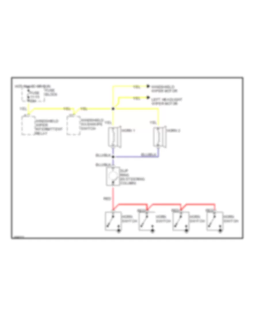
Horn Wiring Diagram for Volvo 940 1994
List of elements for Horn Wiring Diagram for Volvo 940 1994:
- Fuse 11-15 25a
- Fuse block
- Horn 1
- Horn 2
- Horn switch
- Hot in acc or run
- Left headlight wiper motor
- Red
- Slip ring (in steering column)
- Windshield wash/wipe switch
- Windshield wiper intermittent relay
- Windshield wiper motor
INSTRUMENT CLUSTER
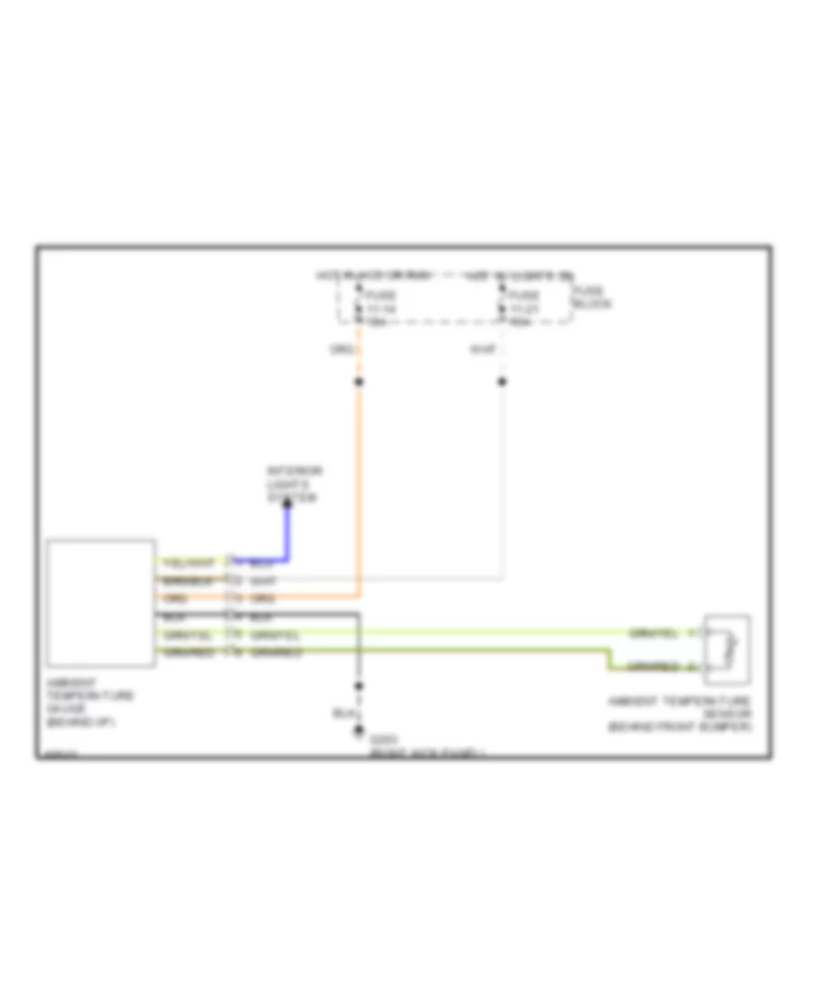
Ambient Temperature Gauge for Volvo 940 1994
List of elements for Ambient Temperature Gauge for Volvo 940 1994:
- Ambient temperature gauge (behind i/p)
- Ambient temperature sensor (behind front bumper)
- Fuse 11-14 15a
- Fuse 11-21 15a
- Fuse block
- G203 (right kick panel)
- Hot in acc or run
- Hot w/ lights on
- Interior lights system
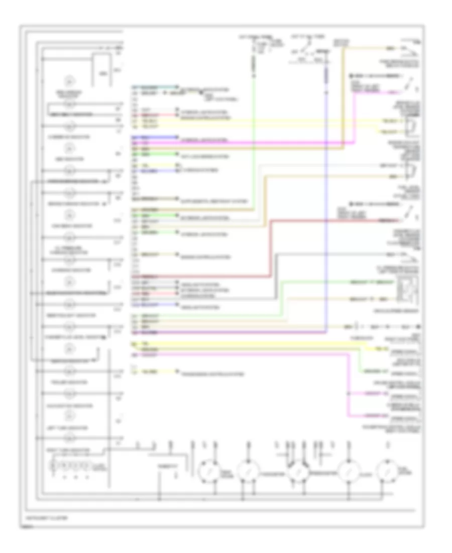
Instrument Cluster Wiring Diagram for Volvo 940 1994
List of elements for Instrument Cluster Wiring Diagram for Volvo 940 1994:
- Abs indicator
- Acc
- Anti-lock brake system
- B10
- B11
- B12
- Brake fluid level sensor (in master cylinder)
- Brake warning indicator
- Bulb malfunction indicator
- C10
- C11
- C12
- C13
- C14
- C15
- C16
- C17
- C18
- Charging indicator
- Charging system
- Clock
- Cruise control module (left kick panel)
- Ecc module (center of i/p)
- Engine controls system
- Engine coolant temperature sensor (left side of engine
- Exterior lights system
- Fuel gauge
- Fuel level sensor (in fuel tank)
- Fuse 11-5 15a
- Fuse block
- G100 (front of left front fender)
- G200 (left kick panel)
- G203 (right kick panel)
- Headlights system
- High beam indicator
- Hot at all times
- Ignition switch
- Illumi- nation
- Indicator
- Instrument cluster
- Interior lights system
- Left turn indicator
- Malfunction indicator
- Off
- Oil pressure
- Oil pressure switch (left side of engine)
- Overdrive indicator
- Overdrive relay (in fuse block)
- Park brake switch (below console)
- Parking brake indicator
- Powertrain control module (right kick panel)
- Rear foglight indicator
- Red
- Rheostat
- Right turn indicator
- Run
- Seat belt indicator
- Service indicator
- Speed signal
- Speedometer
- Srs
- Srs warning
- Start
- Tachometer
- Temp gauge
- Trailer indicator
- Transmission controls system
- Vehicle speed sensor
- Warning indicator
- Warning systems
- Washer fluid level indicator
- Washer fluid level sensor (in washer fluid reservoir)
INTERIOR LIGHTS
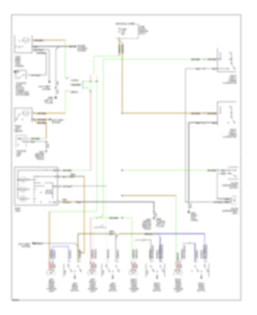
Courtesy Lamp Wiring Diagram for Volvo 940 1994
List of elements for Courtesy Lamp Wiring Diagram for Volvo 940 1994:
- 31b
- Anti-theft system
- Fuse 11-5 15a
- Fuse block (center of i/p)
- G203 (right kick panel)
- G407 (center rear of trunk)
- G999 (left "d" pillar)
- G999 (wagon) (left "d" pillar)
- Glove compartment light
- Glove compartment switch
- Hot at all times
- Left front door open warning light
- Left front door switch
- Left rear door open warning light
- Left rear door switch
- Load area roof light (wagon)
- Power antenna system
- Red
- Right front door open warning light
- Right front door switch
- Right rear door open warning light
- Right rear door switch
- Right vanity mirror illumination
- Roof light
- Sedan
- Solid state
- Tailgate door switch (wagon) (upper left hatch door)
- Tailgate lock unit
- Trunk light (sedan)
- Wagon
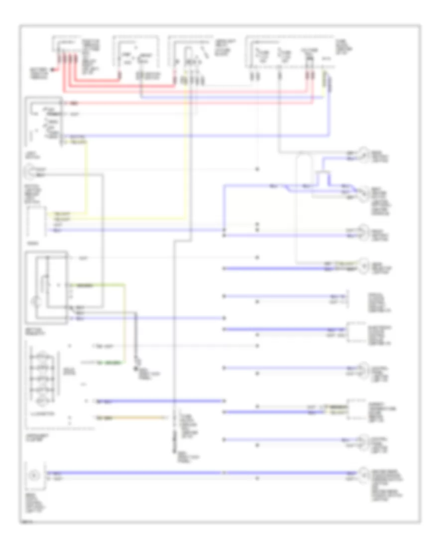
Instrument Illumination Wiring Diagram for Volvo 940 1994
List of elements for Instrument Illumination Wiring Diagram for Volvo 940 1994:
- (in fuse block)
- (right kick panel)
- A16
- Acc
- Ambient temperature gauge (behind left i/p)
- Battery positive terminal
- Beam width control (optional) (left i/p)
- Control panel lighting (left i/p)
- Electronic climate control module (center i/p)
- Front ashtray lighting
- Fuse 11-21 15a
- Fuse 11-22 15a
- Fuse block (center of i/p)
- Fuse block ground rail (center of i/p)
- G203 (right kick panel)
- Gear selector lighting
- Head
- Headlight relay
- Heated rear windows/door mirrors switch lighting (or) heated rear window switch lighting
- Ignition switch
- Illumination
- Instrument cluster
- Light switch
- Manual climate control module 1 (center i/p)
- Off
- Park
- Park head
- Positive terminal voltage rail 15-1 (below right (or left) of i/p)
- Radio
- Rear ashtray lighting
- Red
- Run
- Seat heater switch lighting (optional) (center console)
- Setting rheostat
- Solid state
- Start
- Switch lighting (behind light switch)
- Voltage rail 15-2
MEMORY SYSTEMS
Memory Seat Wiring Diagram for Volvo 940 1994
List of elements for Memory Seat Wiring Diagram for Volvo 940 1994:
- (below center console) g302
- 1992 & early 1993
- Aft
- Back
- Backrest switch
- C10
- C11
- C12
- C13
- C14
- Computer data lines system
- D10
- D11
- D12
- D13
- D14
- D15
- D16
- Down
- Fore
- Fore-aft switch
- Forw
- Front edge switch
- Fuse 11-15 25a
- Fuse 11-3 30a
- Fuse block (below center of dash)
- Hot at all times
- Hot in acc or run
- Late 1993 & 1994
- Late 1993 & 1994 a2
- Left front memory switch (on left side of seat)
- Left front seat backrest motor
- Left front seat fore-aft motor
- Left front seat front edge up-down motor
- Left front seat memory control module (under left front seat)
- Left front seat rear edge up-down motor
- M1+
- M1-
- M2+
- M2-
- M3+
- M3-
- M4+
- M4-
- Mem
- R1+
- R1-
- R2+
- R2-
- R3+
- R3-
- R31
- R4+
- R4-
- Rear edge switch
- Red
- Seats system (right front seat control module)
- Vg1
- Vg2
- Vg3/4
- Vr1
- Vr2
- Vr3
- Vr4
POWER ANTENNA
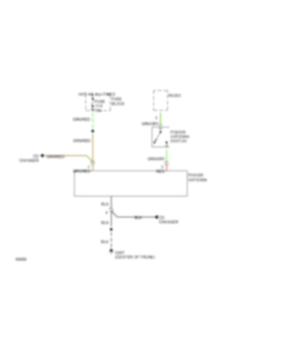
Power Antenna Wiring Diagram for Volvo 940 1994
List of elements for Power Antenna Wiring Diagram for Volvo 940 1994:
- Cd changer
- Fuse 11-5 15a
- Fuse block
- G407 (center of trunk)
- Hot at all times
- Power antenna
- Power antenna switch
- Radio
- Red
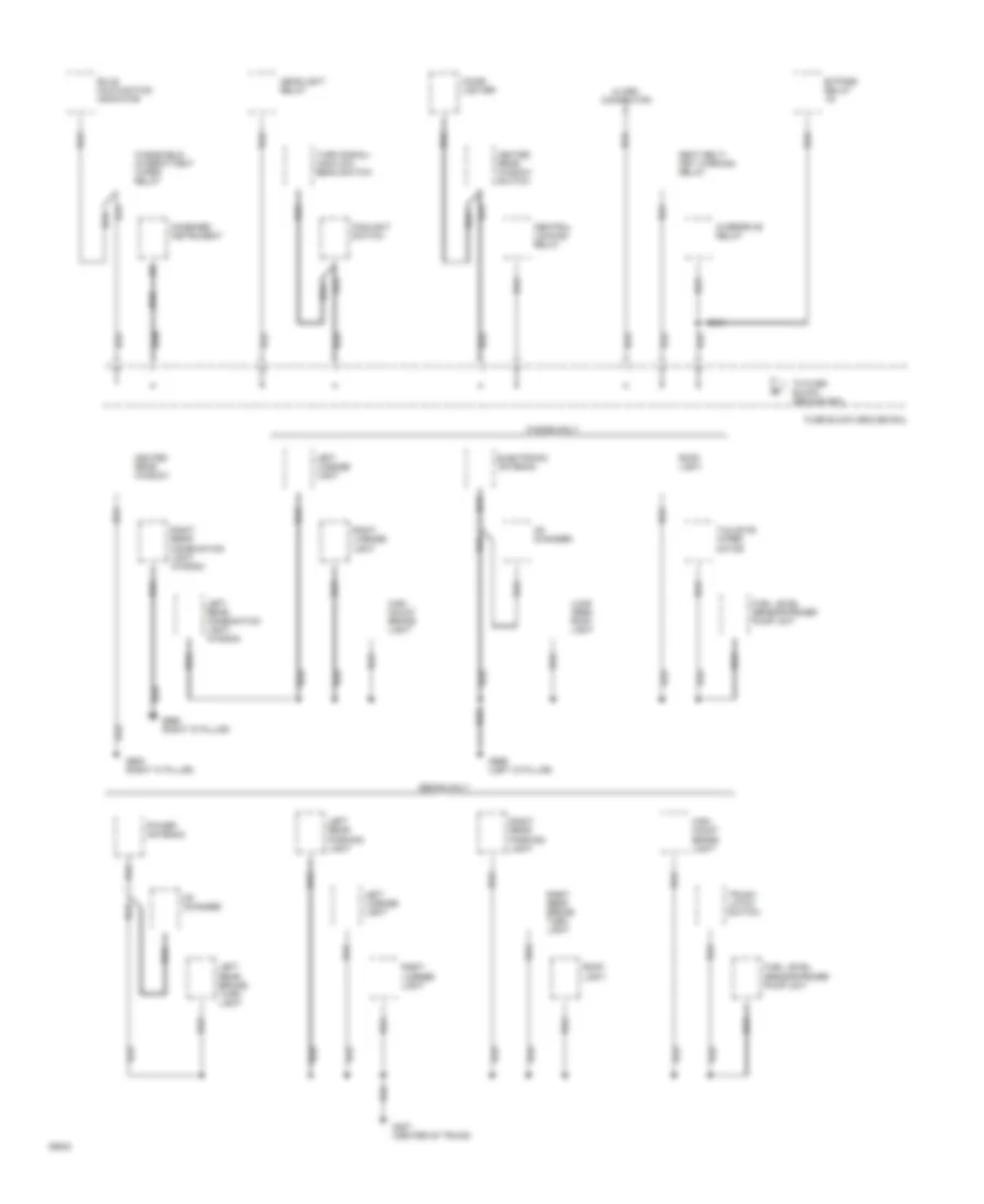
POWER DISTRIBUTION
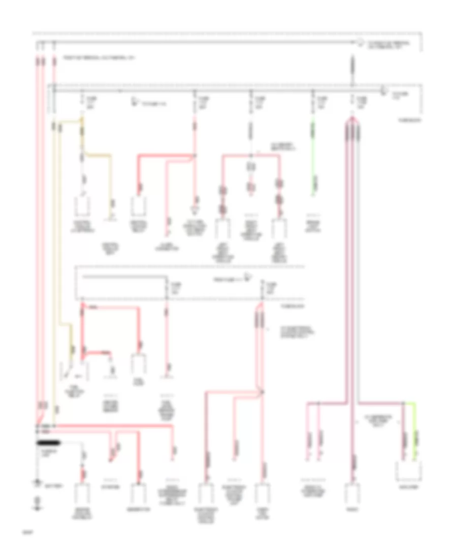
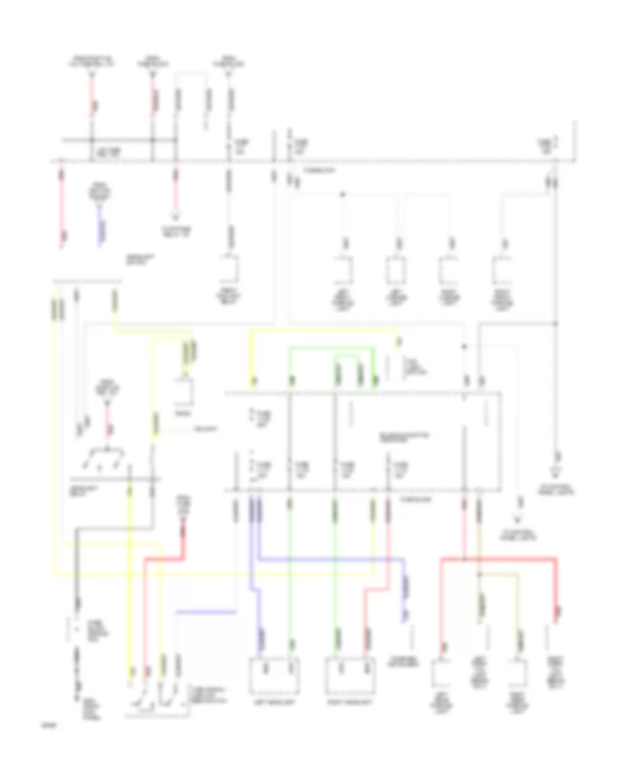
Power Distribution Wiring Diagram (1 of 6) for Volvo 940 1994
List of elements for Power Distribution Wiring Diagram (1 of 6) for Volvo 940 1994:
- (w/ electronic climate control system only)
- (w/ memory seats only)
- (w/ seperate amplifier only)
- Alarm connector
- Amplifier
- B from fuse 11-1
- Battery
- Brake light switch
- Cabin fan motor
- Central locking relay
- Control module ez-k
- Control module lh-jetronic
- Electronic climate control module
- Electronic climate control power unit
- Engine cooling fan relay
- Fuel injection relay
- Fuel level sensor/ primer pump
- Fuel pump
- Fuse 11-1 25a
- Fuse 11-11 15a
- Fuse 11-2 25a
- Fuse 11-26 15a
- Fuse 11-3 30a
- Fuse 11-4 15a
- Fuse 11-6 30a
- Fuse block
- Fusible link
- Generator
- Heated oxygen sensor
- Left front seat memory module
- Left front seat operating module
- Pnk
- Positive terminal voltage rail 15-1
- Radio
- Radio interference suppression relay (turbo only)
- Radio w/ integrated amplifier
- Red
- Red/
- Right front seat operating module
- Starter
- To fuse 11-5
- To fuse 11-6
- To positive terminal voltage rail 15-1
- To turn signal/high low beam switch
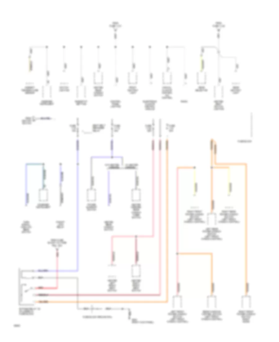
Power Distribution Wiring Diagram (2 of 6) for Volvo 940 1994
List of elements for Power Distribution Wiring Diagram (2 of 6) for Volvo 940 1994:
- Acc
- Alarm connector
- C from 11-3, 11-4 & 11-26
- Cd changer
- Clock (combined instrument)
- Cruise control module
- Electronic antenna (wagon)
- From positive a voltage rail 15-1
- Fuse 11-5 15a
- Fuse block
- Glove compartment light
- Ignition switch
- Left front door open light
- Left rear door open light
- Left vanity mirror illum- ination
- Load area roof light (wagon)
- Off
- P-shift lock relay
- Pnk
- Positive voltage rail 15-1
- Power antenna (sedan)
- Red
- Right front door open light
- Right rear door open light
- Right vanity mirror illum- ination
- Roof light
- Run
- Seat belt/ ignition warning relay
- Service starter socket
- Start
- Start inhibit switch
- To fuse block voltage rail 15-2
- To fuses 11-12, 11-13, 11-24 & ignition coil
- To fuses 11-14, 11-15 & 11-16
- To fuses 11-9 & 11-10
- To head- light switch
- To headlight relay
- To positive voltage rail 15-2
- Trunk light (sedan)
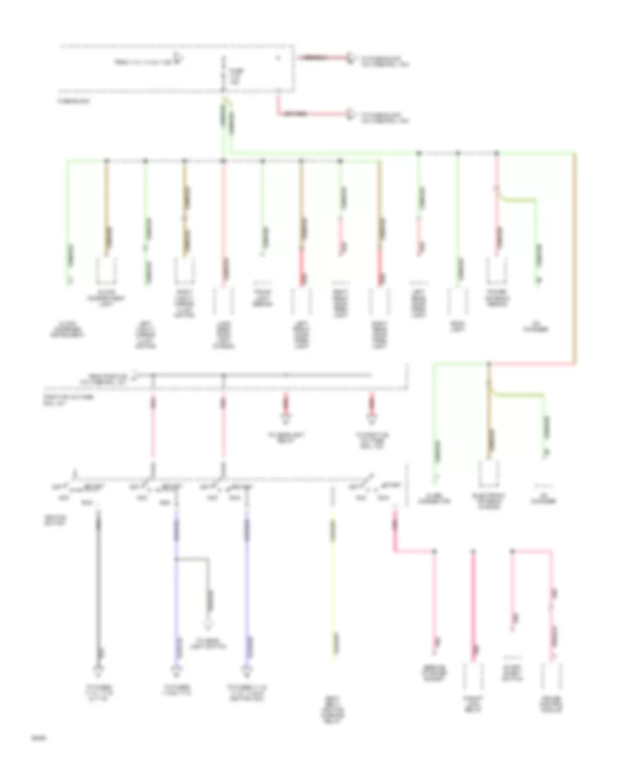
Power Distribution Wiring Diagram (3 of 6) for Volvo 940 1994
List of elements for Power Distribution Wiring Diagram (3 of 6) for Volvo 940 1994:
- Bulb malfunction indicator
- C18
- Combined instrument
- Fog light switch
- From fuse 11-2
- From fuse block
- From ignition switch
- From positive rail 15-1
- From positive voltage rail 15-1
- Front foglight relay
- Fuse 11-17 15a
- Fuse 11-18 15a
- Fuse 11-19 15a
- Fuse 11-20 15a
- Fuse 11-21 15a
- Fuse 11-22 15a
- Fuse 11-25 25a
- Fuse 11-7 15a
- Fuse block
- Fuse block ground rail
- G203 (right kick panel)
- Headlight relay
- Headlight switch
- High
- Left front parking light
- Left headlight
- Left license light
- Left park/ tail light (sedan only)
- Left rear parking light
- Low
- Radio
- Red
- Right front parking light
- Right headlight
- Right license light
- Right park/ tail light (sedan only)
- Right rear parking light
- To bypass relay 15i
- To control panel lights
- Turn signal/ high/low beam switch
- Voltage rail 15-2
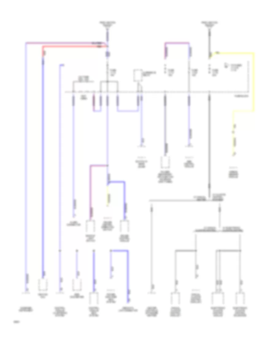
Power Distribution Wiring Diagram (4 of 6) for Volvo 940 1994
List of elements for Power Distribution Wiring Diagram (4 of 6) for Volvo 940 1994:
- Ambient temperature sensor
- Bypass relay 15i (plugged in fuse block)
- Combined instrument
- Control panel lighting
- Electronic climate control module
- From fuse 11-21
- From fuse 11-22
- From fuse block voltage rail 15-2
- From ignition switch
- Front ashtray light
- Fuse 11-10 30a
- Fuse 11-23 25a
- Fuse 11-8 30a
- Fuse 11-9 15a
- Fuse block
- Fuse block ground rail
- G203 (right kick panel)
- Gear selector
- Heated left front seat switch
- Heated mirrors/ rear window timer/ switch
- Heated rear window switch
- Heated right front seat switch
- Heated seat switch lighting
- Left front power window switch (left front window control)
- Left rear power window switch (left front window control)
- Manual climate control a/c control
- P-shift lock relay
- Power sunroof switch
- Radio
- Rear ashtray light
- Rear windows control switch (left front window control)
- Red
- Rheostat setting
- Right front power window switch (left front window control)
- Right front power window switch (right door)
- Right rear power window switch (left front window control)
- Seat belt reminder relay
- Switch lighting
- Turn signal/ high/low beam switch
- W/ heated mirrors
- W/o heated mirrors
Power Distribution Wiring Diagram (5 of 6) for Volvo 940 1994
List of elements for Power Distribution Wiring Diagram (5 of 6) for Volvo 940 1994:
- (not used)
- Abs control module
- Airbag sensor module
- Alarm connector
- Backup light switch
- Combined instrument
- Control module ez-k system
- Control module lh-jetronic system
- Cruise control module
- Cruise control operation switch
- Egr converter
- Electronic climate control module
- Electronic climate control solenoids
- From ignition switch
- Fuse 11-12 15a
- Fuse 11-13 15a
- Fuse 11-16 30a
- Fuse 11-24 15a
- Fuse block
- Heater controls (standard heater)
- Ignition coil
- Manual climate control module 1
- Manual climate control module 2
- Obd data link connector
- Overdrive relay
- Power amplifier ez-k system
- Pulsed secondary air injection solenoid (non turbo)
- Red
- Switch in gear lever
- To fuses 11-14 & 11-15
- Voltage rail 15-9
- W/ climate control systems
- W/ electronic climate control
- W/ manual climate control
- W/ manual heater
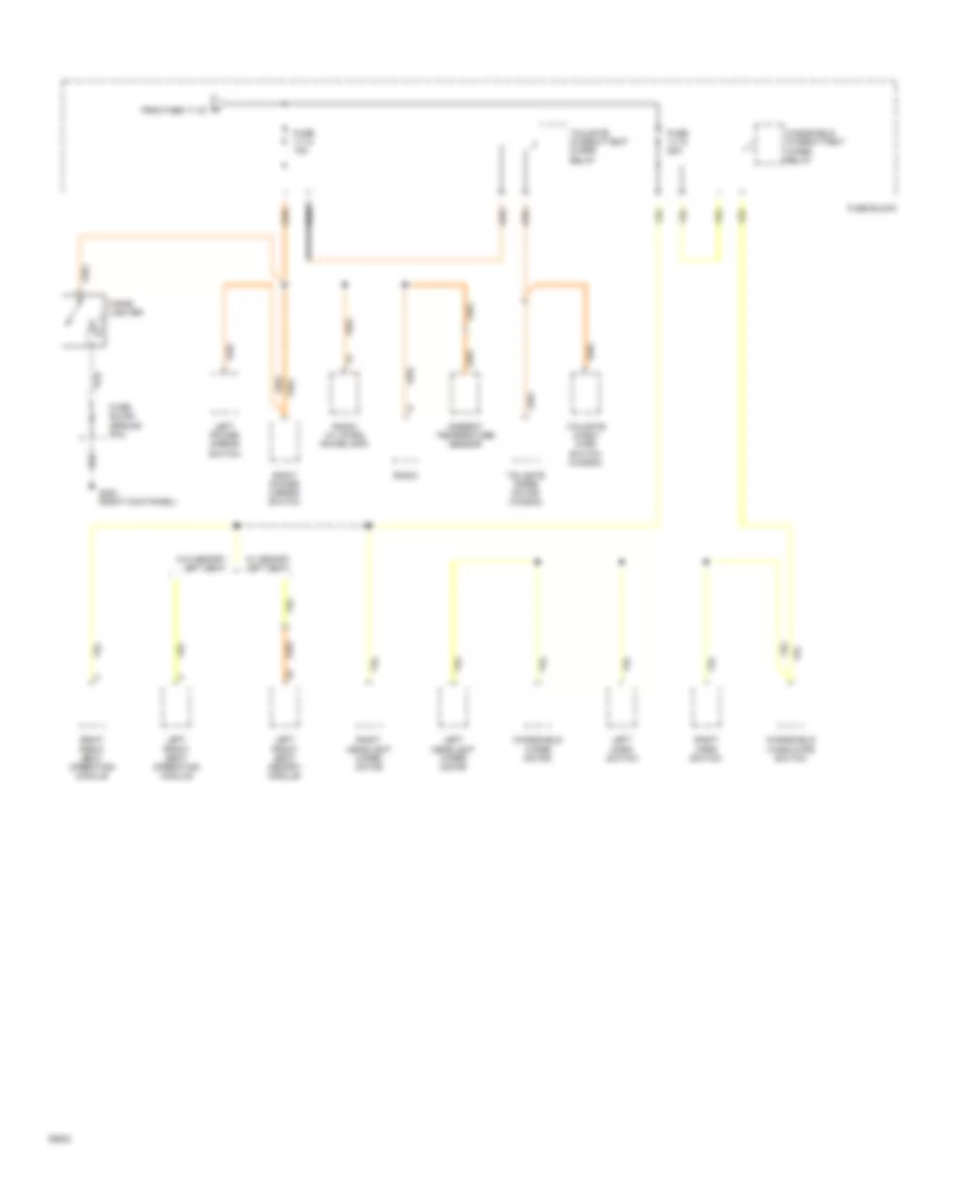
Power Distribution Wiring Diagram (6 of 6) for Volvo 940 1994
List of elements for Power Distribution Wiring Diagram (6 of 6) for Volvo 940 1994:
- Ambient temperature sensor
- Cigar lighter
- Fuse 11-14 15a
- Fuse 11-15 25a
- Fuse block
- Fuse block ground rail
- G203 (right kick panel)
- Left front seat memory module
- Left front seat operating module
- Left headlight wiper motor
- Left horn switch
- Left power mirror switch
- Radio
- Radio (w/ integ- rated amp)
- Right front seat operating module
- Right headlight wiper motor
- Right horn switch
- Right power mirror switch
- S from fuse 11-16
- Tailgate intermittent wiper relay
- Tailgate wash/ wipe switch (wagon)
- Tailgate wiper motor (wagon)
- W/ memory left seat
- W/o memory left seat
- Windshield intermittent wiper relay
- Windshield wash/wipe switch
- Windshield wiper motor
POWER DOOR LOCKS
Power Door Lock Wiring Diagram for Volvo 940 1994
List of elements for Power Door Lock Wiring Diagram for Volvo 940 1994:
- 1993-94
- Anti- theft system
- Central locking relay (in fuse block)
- Fuse 11-2 25a
- Fuse block
- Fuse block ground rail
- G203 (right kick panel)
- Hot at all times
- Interior lights system
- Left front door lock motor
- Left rear door lock motor
- Lock button switch (in left front door)
- Red
- Right front door lock motor
- Right rear door lock motor
- Solid state
- Tailgate lock unit
- W/ tailgate switch
- W/o tailgate switch
POWER MIRRORS
Power Mirror Wiring Diagram for Volvo 940 1994
List of elements for Power Mirror Wiring Diagram for Volvo 940 1994:
- Defoggers system
- Fuse 11-14 25a
- Fuse block (center of dash)
- G203 (right kick panel)
- Heating element
- Hot in acc or run
- Left power door mirror
- Left power mirror switch
- Motor
- Right power door mirror
- Right power mirror switch
POWER SEATS
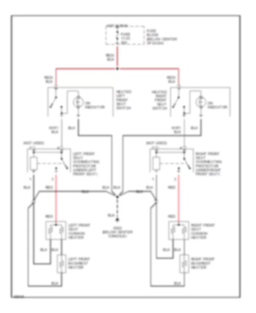
Heated Seats Wiring Diagram, High Output for Volvo 940 1994
List of elements for Heated Seats Wiring Diagram, High Output for Volvo 940 1994:
- (not used)
- Fuse 11-23 25a
- Fuse block (below center of dash)
- G302 (below center console)
- Heated left front seat switch
- Heated right front seat switch
- Hot in run
- Left front backrest heater
- Left front seat cushion heater
- Left front seat overheating protector (under left front seat)
- On indicator
- Red
- Right front backrest heater
- Right front seat cushion heater
- Right front seat overheating protector (under right front seat)
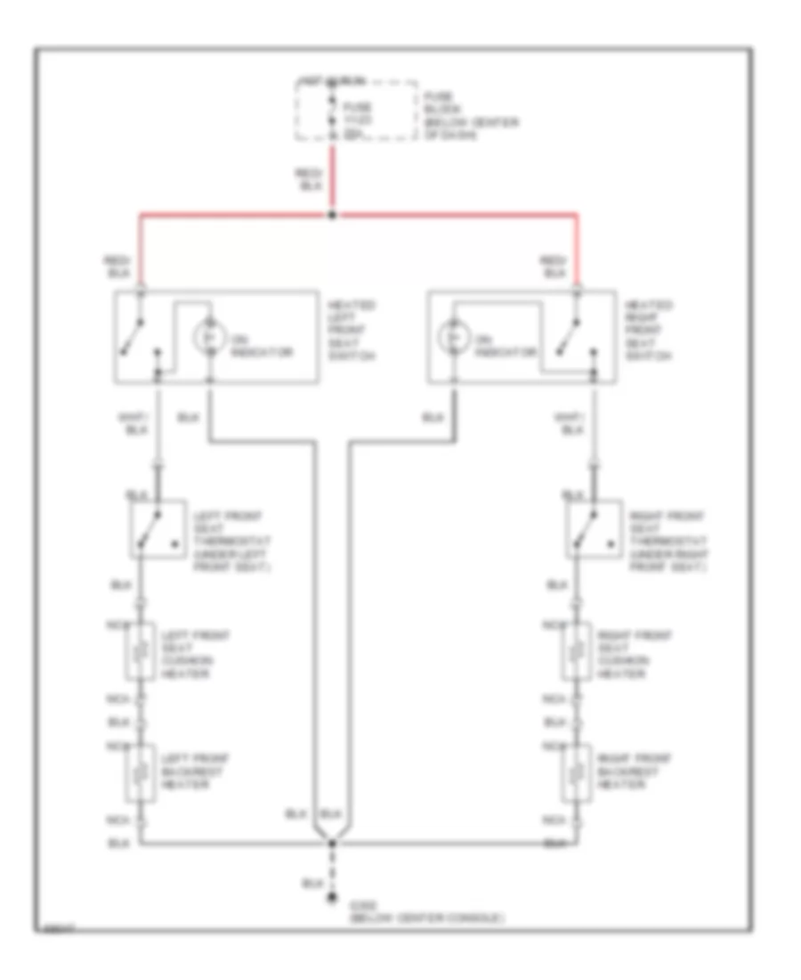
Heated Seats Wiring Diagram, Normal Output for Volvo 940 1994
List of elements for Heated Seats Wiring Diagram, Normal Output for Volvo 940 1994:
- Fuse 11-23 25a
- Fuse block (below center of dash)
- G302 (below center console)
- Heated left front seat switch
- Heated right front seat switch
- Hot in run
- Left front backrest heater
- Left front seat cushion heater
- Left front seat thermostat (under left front seat)
- Nca
- On indicator
- Right front backrest heater
- Right front seat cushion heater
- Right front seat thermostat (under right front seat)
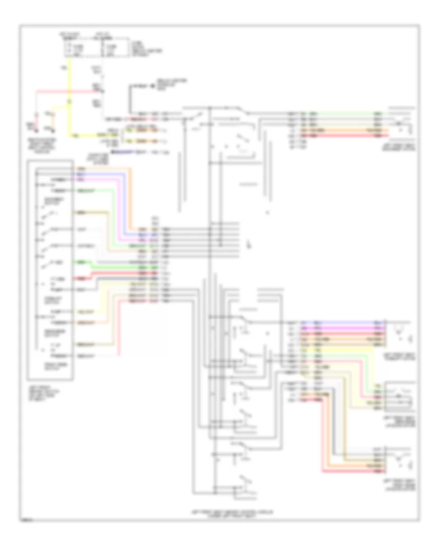
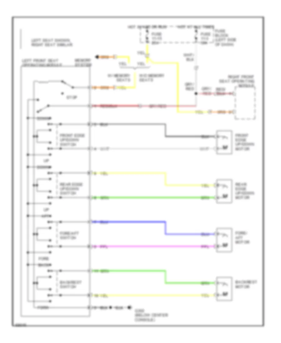
Power Seats Wiring Diagram for Volvo 940 1994
List of elements for Power Seats Wiring Diagram for Volvo 940 1994:
- Aft
- Back
- Backrest motor
- Backrest switch
- Down
- Fore
- Fore/ aft motor
- Fore/aft switch
- Forw
- Front edge up/down motor
- Front edge up/down switch
- Fuse 11-15 25a
- Fuse 11-3 30a
- Fuse block (left side of dash)
- G302 (below center console)
- Hot at all times
- Hot in acc or run
- Left front seat operating module
- Left seat shown, right seat similar
- Memory system
- Rear edge up/down motor
- Rear edge up/down switch
- Right front seat operating module
- Stop
- W/ memory seats
- W/o memory seats
POWER TOP/SUNROOF
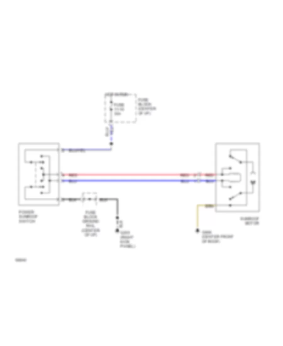
Sunroof Wiring Diagram for Volvo 940 1994
List of elements for Sunroof Wiring Diagram for Volvo 940 1994:
- Fuse 11-10 30a
- Fuse block (center of i/p)
- Fuse block ground rail (center of i/p)
- G908 (center front of roof)
- Hot in run
- Power sunroof switch
- Red
- Sunroof motor
POWER WINDOWS
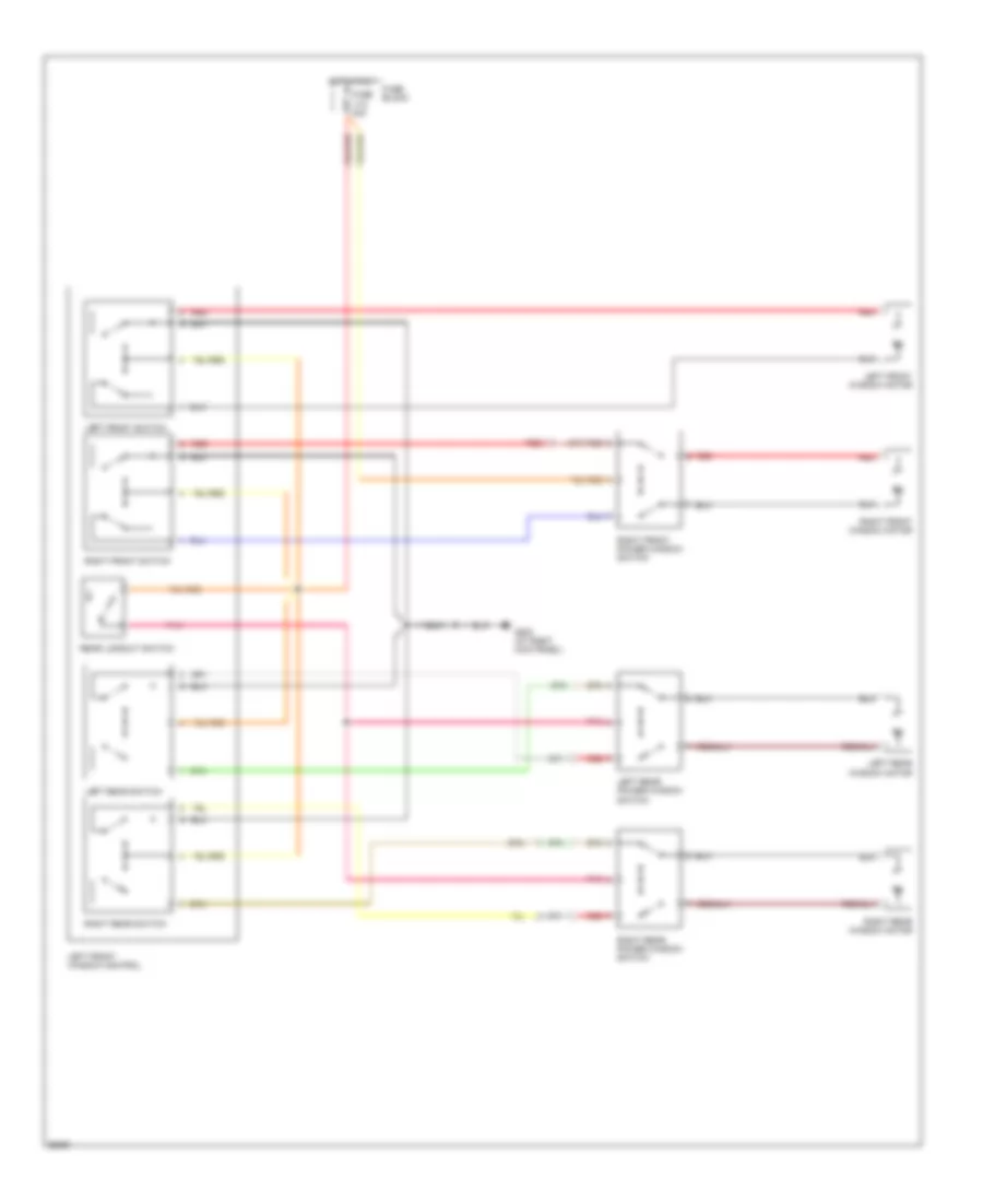
Power Window Wiring Diagram for Volvo 940 1994
List of elements for Power Window Wiring Diagram for Volvo 940 1994:
- Fuse 11-8 30a
- Fuse block
- G203 (at right kick panel)
- Hot in run
- Left front switch
- Left front window control
- Left front window motor
- Left rear power window switch
- Left rear switch
- Left rear window motor
- Pnk
- Rear lockout switch
- Red
- Right front power window switch
- Right front switch
- Right front window motor
- Right rear power window switch
- Right rear switch
- Right rear window motor
RADIO
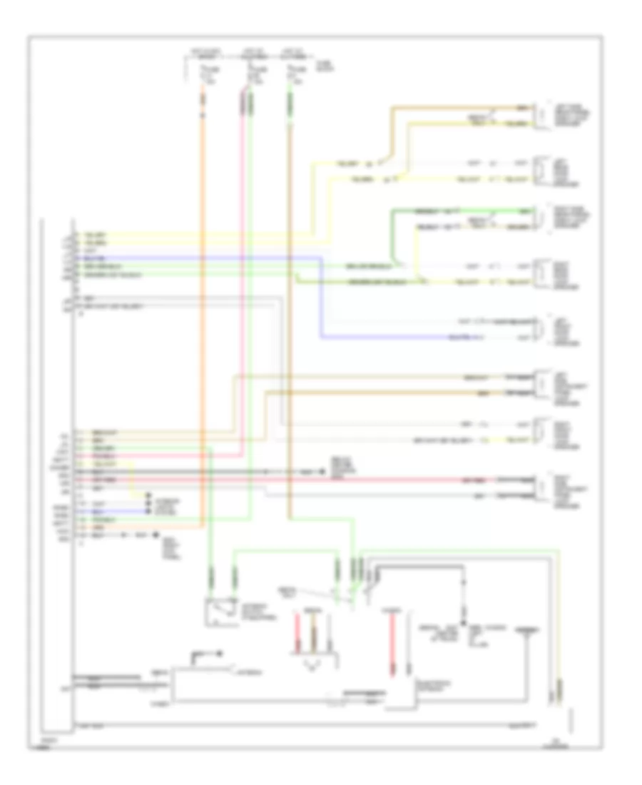
Radio Wiring Diagrams, with Integrated Amplifier for Volvo 940 1994
List of elements for Radio Wiring Diagrams, with Integrated Amplifier for Volvo 940 1994:
- (below center console) g302
- (sedan)
- (wagon)
- +acc
- +ant
- +batt
- +dl
- +dr
- +lf
- +lr
- +rf
- +rheo
- +rr
- -dr
- -rheo
- -rr
- Ant
- Antenna
- Antenna switch (if equipped)
- Cd changer
- Dimmer
- Din
- Electronic antenna
- Fuse 15a
- Fuse block
- G203 (right kick panel)
- G407 (center of trunk)
- G999 (left "d" pillar)
- Gnd
- Hot at all times
- Hot in acc or on
- Interior lights system
- Left front door loud- speaker
- Left rear door loud- speaker
- Left side instrument panel loud- speaker
- Left side rear parcel shelf loud- speaker
- Nca
- Radio
- Red
- Right front door loud- speaker
- Right rear door loud- speaker
- Right side instrument panel loud- speaker
- Right side rear parcel shelf loud- speaker
- Sedan
- Sedan only
- Wagon
- _dl
- _lf
- _lr
- _rf
Radio Wiring Diagrams, with Separated Amplifier for Volvo 940 1994
List of elements for Radio Wiring Diagrams, with Separated Amplifier for Volvo 940 1994:
- (behind left side of dash) amplifier
- (right kick panel)
- (sedan)
- (wagon)
- +batt
- Acc+
- Ant
- Antenna
- Antenna switch (if equipped)
- Cd changer
- Dimmer
- Din
- Dl+
- Dl-
- Dr+
- Dr-
- Electronic antenna
- Fuse 15a
- Fuse block
- G203
- G203 (right kick panel)
- G407 (center of trunk)
- G999 (left "d" pillar)
- Gnd
- Hot at all times
- Hot in acc or on
- Interior lights system
- Left front door loud- speaker
- Left rear door loud- speaker
- Left side instrument panel loud- speaker
- Left side rear parcel shelf loud- speaker
- Lf+
- Lf-
- Lr+
- Lr-
- Nca
- Pwr ant
- Radio
- Red
- Rf+
- Rf-
- Rheo+
- Rheo-
- Right front door loud- speaker
- Right rear door loud- speaker
- Right side instrument panel loud- speaker
- Right side rear parcel shelf loud- speaker
- Rr+
- Rr-
- Sedan
- Sedan only
- Wagon
SHIFT INTERLOCKS
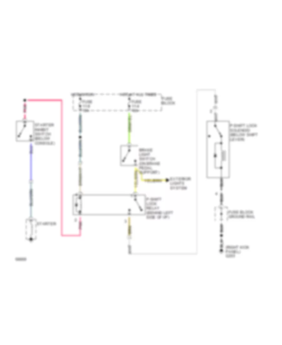
Shift Interlock Wiring Diagram for Volvo 940 1994
List of elements for Shift Interlock Wiring Diagram for Volvo 940 1994:
- (right kick panel) g203
- Exterior lights system
- Fuse 11-4 10a
- Fuse 11-9 15a
- Fuse block
- Fuse block ground rail
- Hot at all times
- Hot in run
- P-shift lock relay (behind left side of i/p)
- P-shift lock solenoid (below shift lever)
- Pnk
- Starter
- Starter inhibit switch (below console)
STARTING/CHARGING
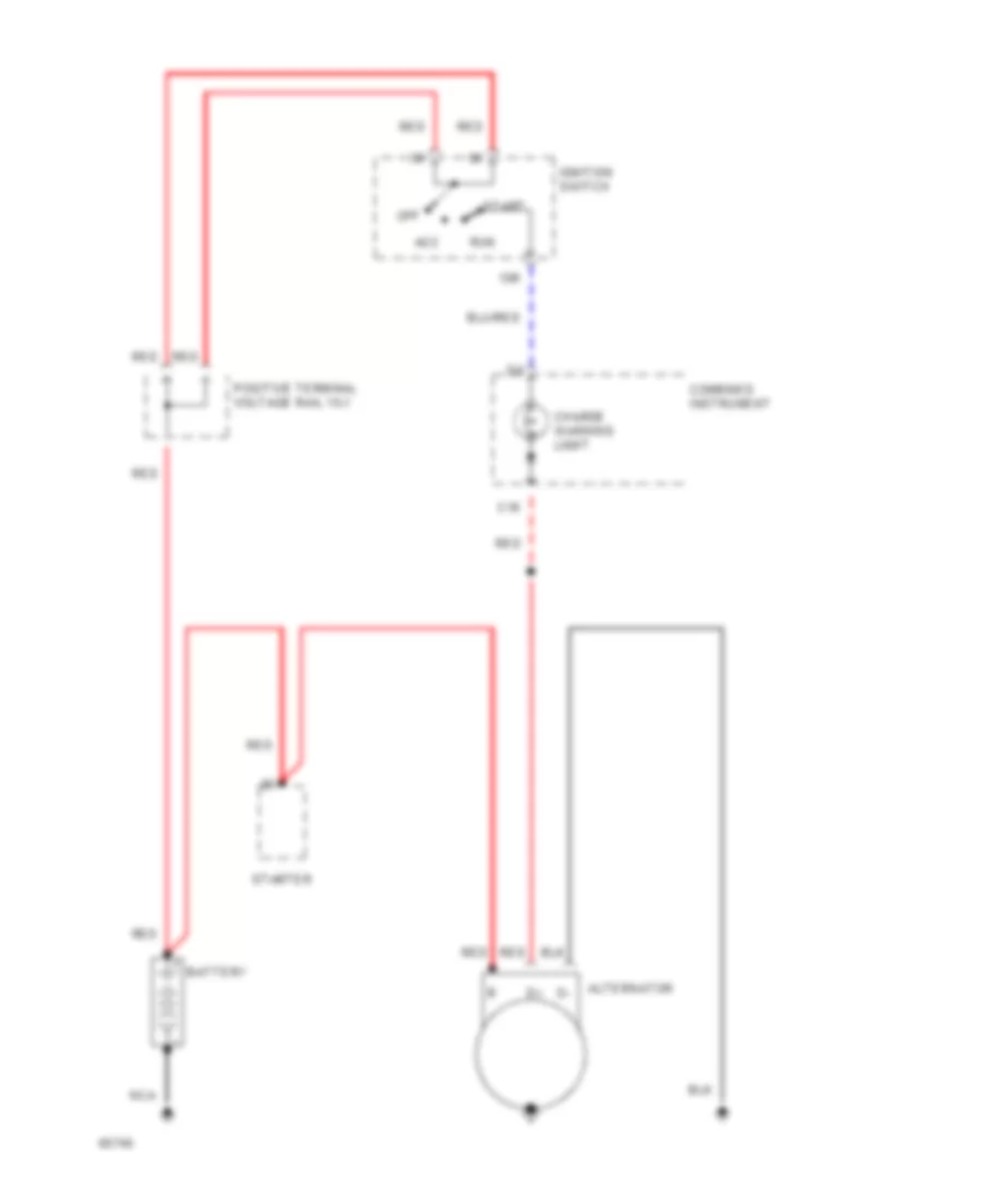
Charging Wiring Diagram for Volvo 940 1994
List of elements for Charging Wiring Diagram for Volvo 940 1994:
- 15r
- Acc
- Alternator
- Battery
- C16
- Charge warning light
- Combined instrument
- Ignition switch
- Nca
- Off
- Positive terminal voltage rail 15-1
- Red
- Run
- Start
- Starter
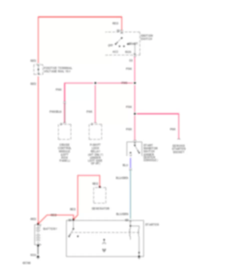
Starting Wiring Diagram for Volvo 940 1994
List of elements for Starting Wiring Diagram for Volvo 940 1994:
- Acc
- Battery
- Cruise control module (left kick panel)
- Generator
- Ignition switch
- Nca
- Off
- P-shift lock relay (a/t only) (under left side of i/p)
- Pnk
- Positive terminal voltage rail 15-1
- Red
- Run
- Service starter socket
- Start
- Start inhibitor switch (under center console)
- Starter
SUPPLEMENTAL RESTRAINTS
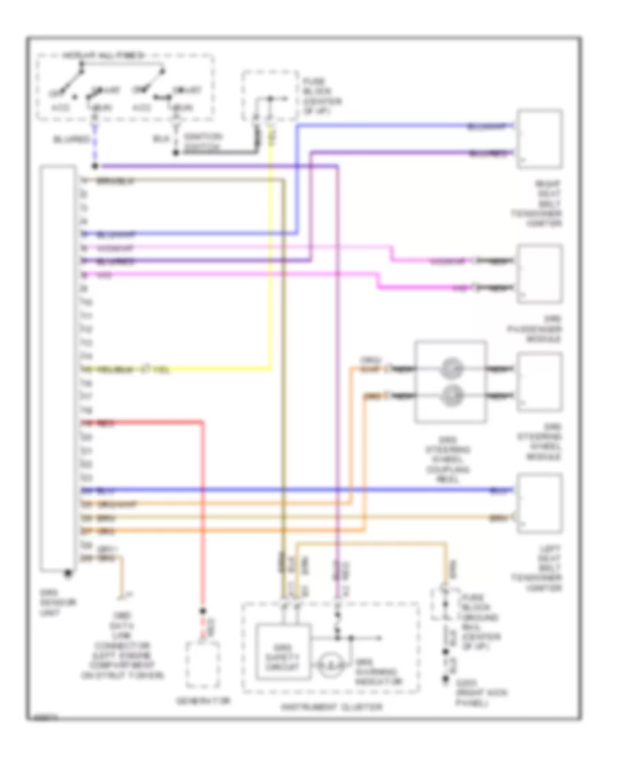
Supplemental Restraint Wiring Diagram for Volvo 940 1994
List of elements for Supplemental Restraint Wiring Diagram for Volvo 940 1994:
- A11
- Acc
- Fuse block (center of i/p)
- Fuse block ground rail (center of i/p)
- G203 (right kick panel)
- Generator
- Hot at all times
- Ignition switch
- Instrument cluster
- Left seat belt tensioner igniter
- Nca
- Obd data link connector (left engine compartment on strut tower)
- Off
- Red
- Right seat belt tensioner igniter
- Run
- Srs passenger module
- Srs safety circuit
- Srs sensor unit
- Srs steering wheel coupling reel
- Srs steering wheel module
- Srs warning indicator
- Start
TRANSMISSION
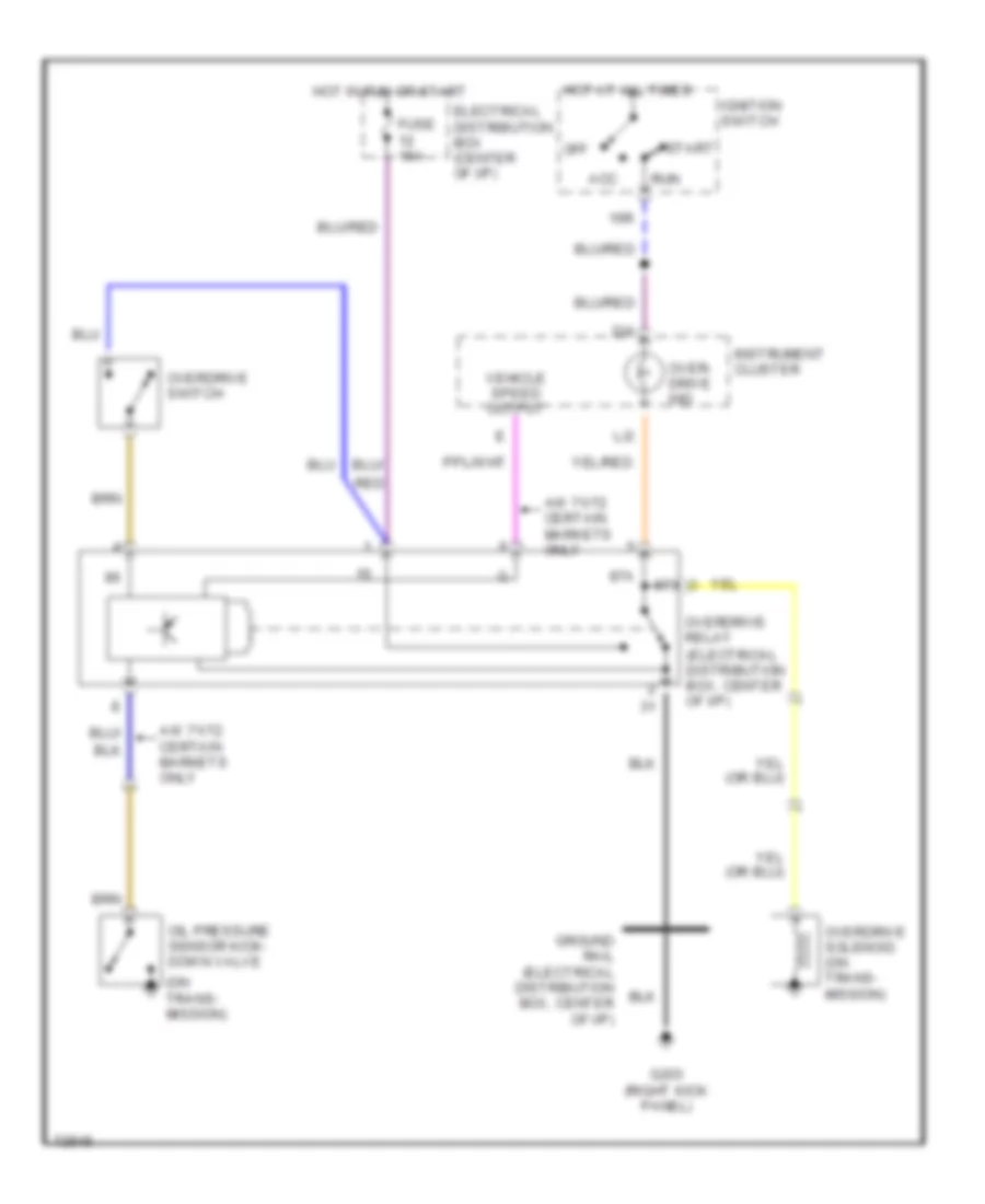
Overdrive Wiring Diagram, A/T for Volvo 940 1994
List of elements for Overdrive Wiring Diagram, A/T for Volvo 940 1994:
- (on trans- mission)
- 15r
- 87a
- Acc
- Aw 71/72 certain markets only
- D/4
- Electrical distribution box (center of i/p)
- Fuse 15a
- G203 (right kick panel)
- Ground rail (electrical distribution box, center of i/p)
- Hot at all times
- Hot in run or start
- Ignition switch
- Instrument cluster
- L/2
- Off
- Oil pressure sensor kick- down valve
- Over- drive ind
- Overdrive relay (electrical distribution box, center of i/p)
- Overdrive solenoid (on trans- mission)
- Overdrive switch
- Red
- Run
- Start
- Vehicle speed output
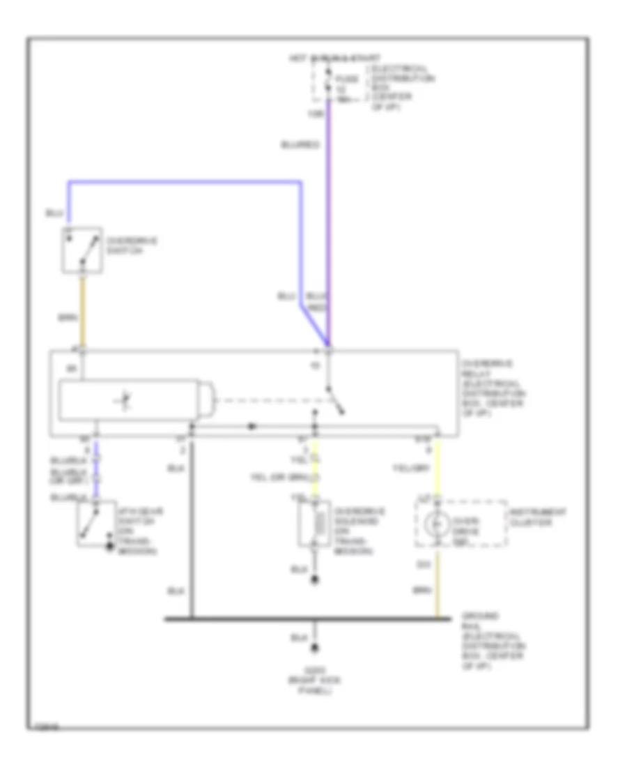
Overdrive Wiring Diagram, M/T for Volvo 940 1994
List of elements for Overdrive Wiring Diagram, M/T for Volvo 940 1994:
- 15r
- 4th gear switch (on trans- mission)
- 87b
- D/3
- Electrical distribution box (center of i/p)
- Fuse 15a
- G203 (right kick panel)
- Ground rail (electrical distribution box, center of i/p)
- Hot in run & start
- Instrument cluster
- L/1
- Over- drive ind
- Overdrive relay (electrical distribution box, center of i/p)
- Overdrive solenoid (on trans- mission)
- Overdrive switch
- Red
WARNING SYSTEMS
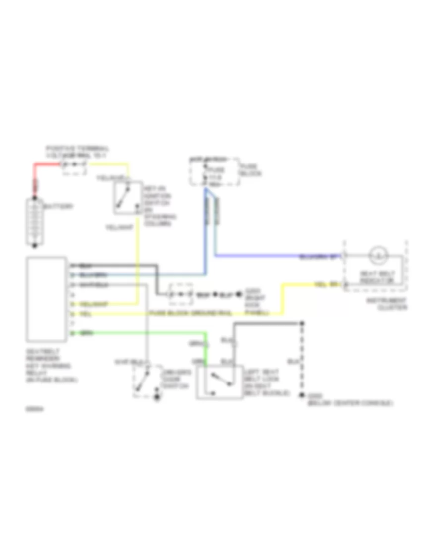
Warning System Wiring Diagrams for Volvo 940 1994
List of elements for Warning System Wiring Diagrams for Volvo 940 1994:
- Battery
- Driver's door switch
- Fuse 11-9 15a
- Fuse block
- Fuse block ground rail
- G203 (right kick panel)
- G302 (below center console)
- Hot in run
- Instrument cluster
- Key-in ignition switch (in steering column)
- Left seat belt lock (in seat belt buckle)
- Positive terminal voltage rail 15-1
- Red
- Seat belt indicator
- Seatbelt reminder/ key warning relay (in fuse block)
WIPER/WASHER
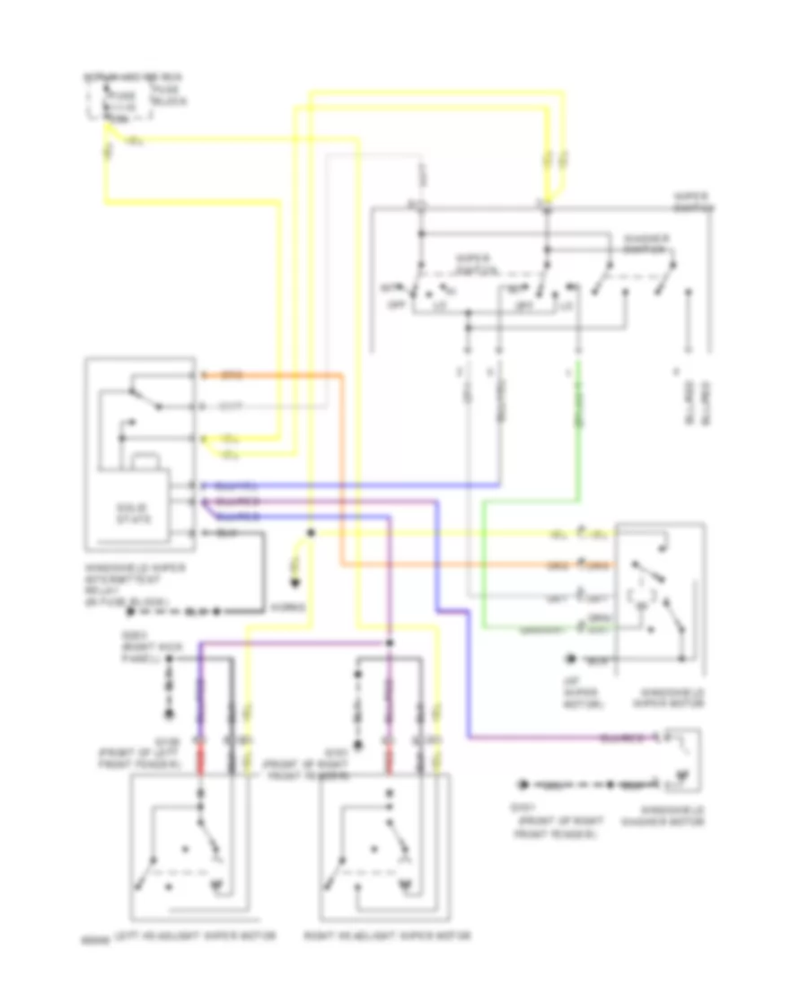
Front Wiper/Washer & Headlamp Wiper/Washer Wiring Diagram for Volvo 940 1994
List of elements for Front Wiper/Washer & Headlamp Wiper/Washer Wiring Diagram for Volvo 940 1994:
- (at wiper motor)
- (front of right
- Front fender)
- Fuse 11-15 25a
- Fuse block
- G100 (front of left front fender)
- G101
- G101 (front of right front fender)
- G203 (right kick panel)
- Horns
- Hot in acc or run
- Int
- Left headlight wiper motor
- Off
- Red
- Right headlight wiper motor
- Solid state
- Washer switch
- Windshield washer motor
- Windshield wiper intermittent relay (in fuse block)
- Windshield wiper motor
- Wiper switch
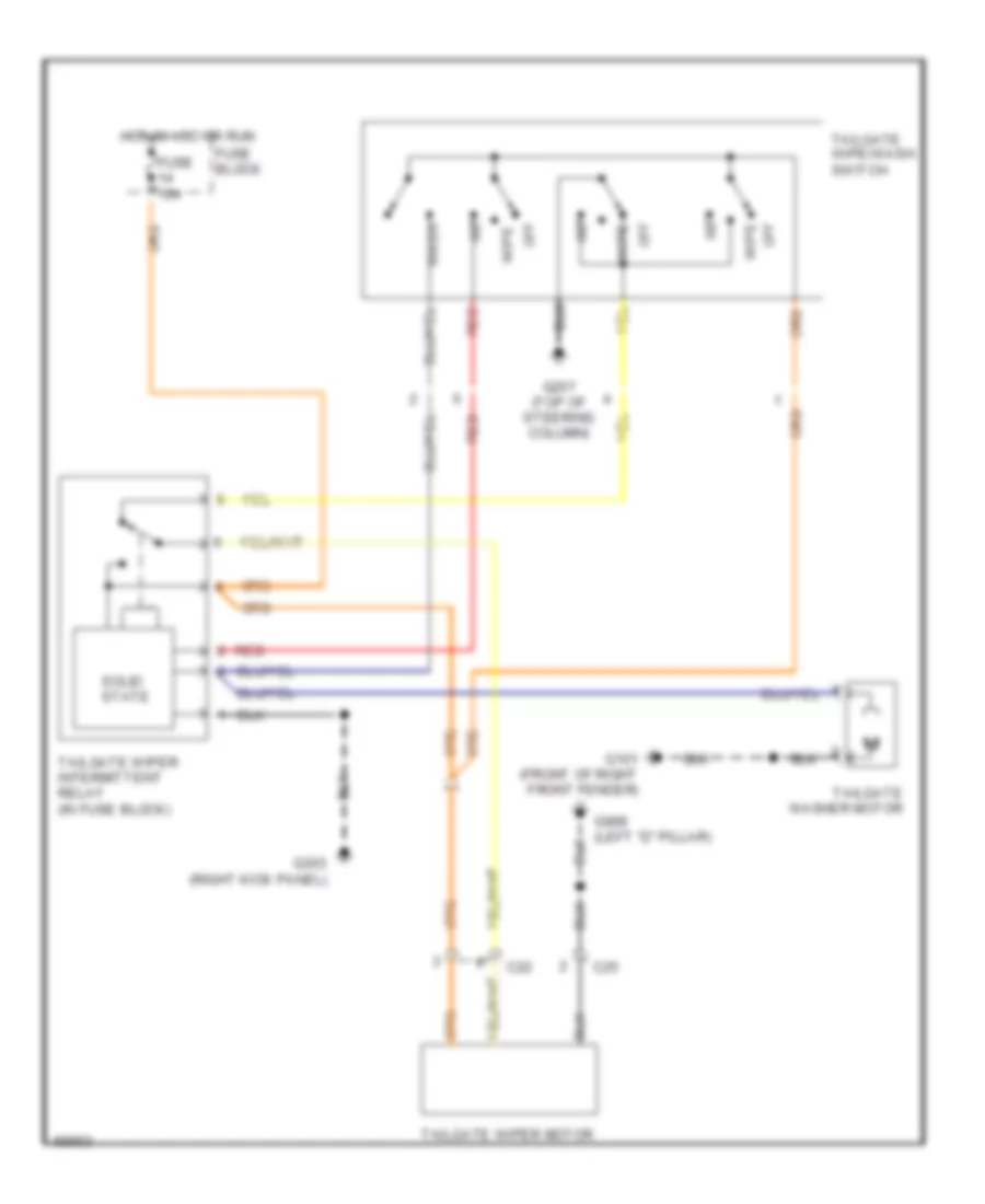
Rear Wiper/Washer Wiring Diagram for Volvo 940 1994
List of elements for Rear Wiper/Washer Wiring Diagram for Volvo 940 1994:
- C22
- C25
- Fuse 15a
- Fuse block
- G101 (front of right front fender)
- G203 (right kick panel)
- G207 (top of steering column)
- G999 (left "d" pillar)
- Hot in acc or run
- Int
- Off
- Red
- Solid state
- Tailgate washer motor
- Tailgate wipe/wash switch
- Tailgate wiper intermittent relay (in fuse block)
- Tailgate wiper motor
- Wash
- Wipe

 Čeština
 Dansk
Dansk Deutsch
 Ελληνικά
 English
 English
 Español
 Suomi
Suomi Français
 Français
 עברית
עברית Hrvatski
 Magyar
 Italiano
 日本語
日本語 한국어
한국어 Nederlands
 Polski
 Português
 Română
 Русский
 Slovenčina
 Slovenščina
 Svenska
 Türkçe
 中文 (中国)