Автомтическая коробка Передач (АКПП) Полная привод (4WD) Блокировка Дифференциала
3.8L
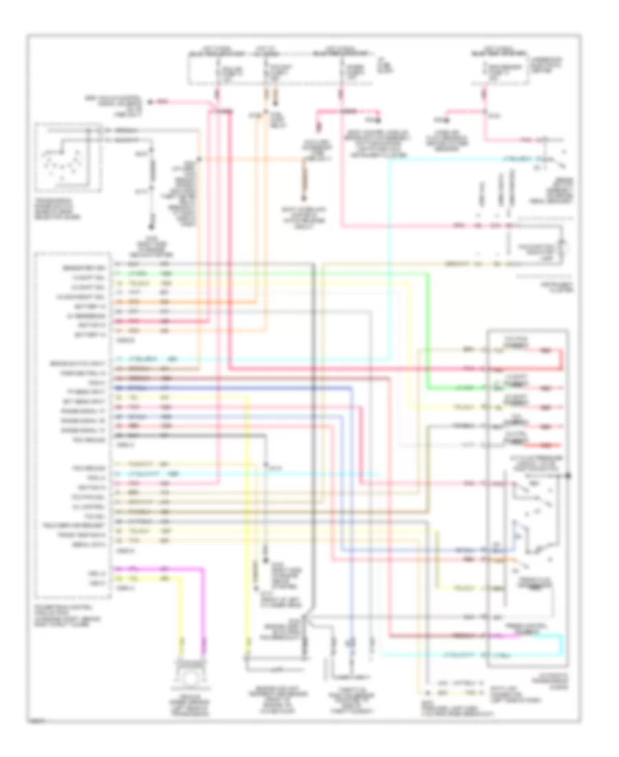
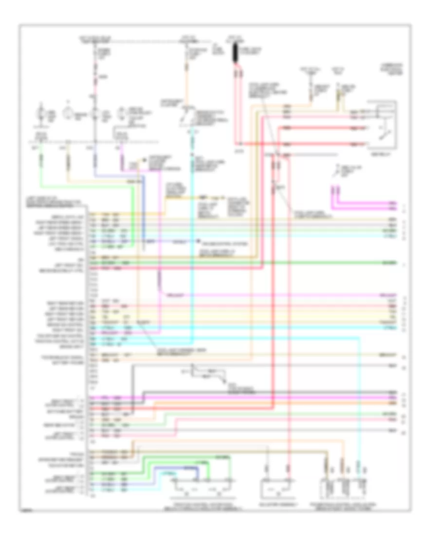
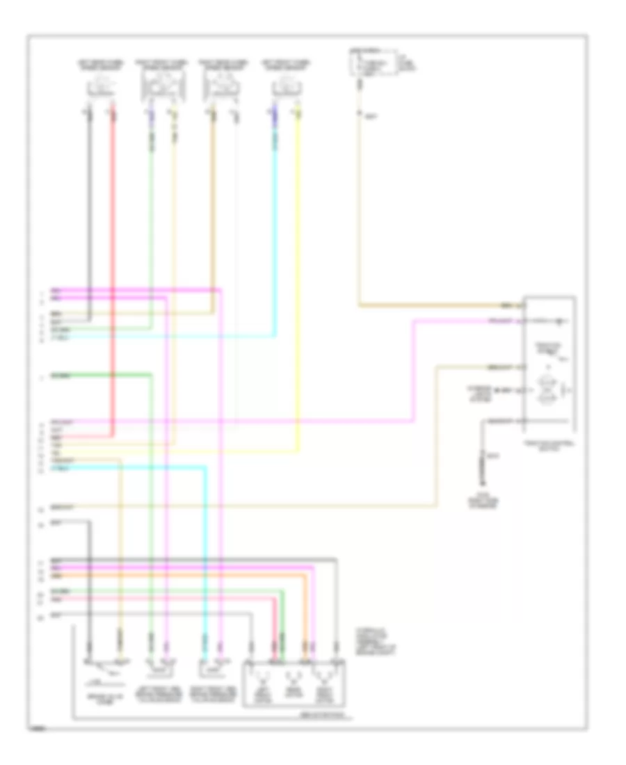
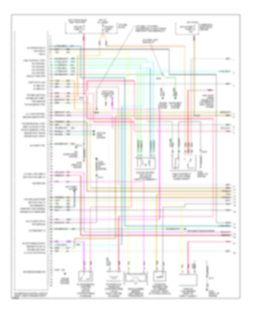
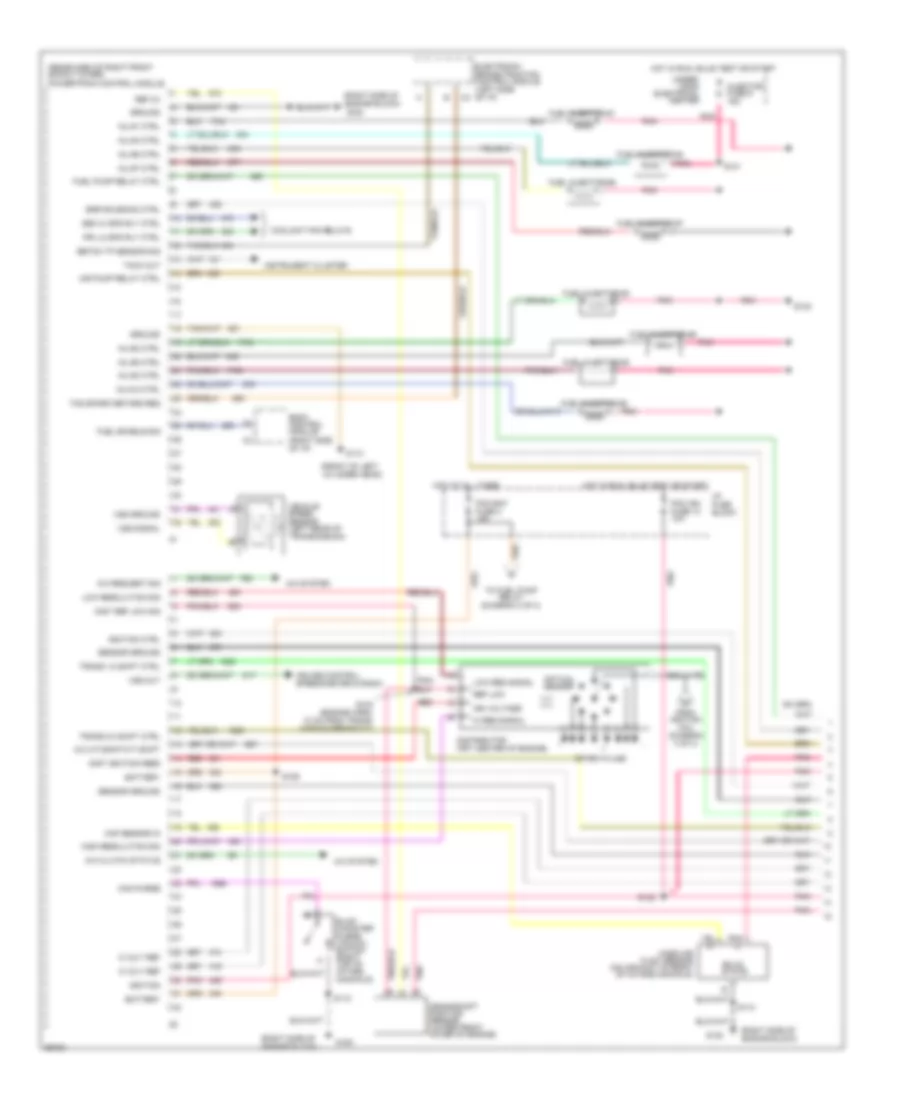
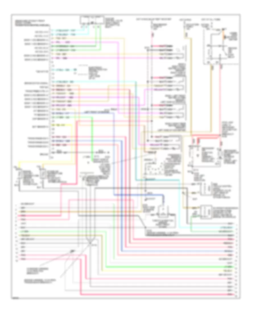
3.8L (VIN K), Электросхема коробки передач АКПП для Pontiac Firebird 1997
 https://portal-diagnostov.com/license.html
Automotive Electricians Portal FZCO
Automotive Electricians Portal FZCO
https://portal-diagnostov.com/license.html
https://portal-diagnostov.com/license.html
Automotive Electricians Portal FZCO
Automotive Electricians Portal FZCO
3.8L (VIN K), Электросхема коробки передач АКПП для Pontiac Firebird 1997 - Список элементов:
- (fwd lamp harn, about 11 cm from main branch, in traction control module breakout) s270
- 1-2 ctrl sol
- 1-2 shift sol
- 2-3 ctrl sol
- 2-3 shift sol
- 2nd gear start ind
- 2nd gear start ind ctrl
- 2nd gear start sw in
- 3-2 ctrl sol
- 3-2 downshift sol
- 5v reference
- Actuators fuse 2 15a
- Automatic transmission
- Body control module, brake switch assembly, daytime running lights module & instrument cluster
- Brake switch assembly (under left side of dash)
- Brake/tcc sw in
- Data link connector (partial) (under left side of dash)
- Dlc class 2 data
- Ect sens in
- Egr valve
- Eng sensor fuse 10 20a
- Engine controls system
- Engine coolant temperature sensor (front of lower intake manifold, under throttle body assy)
- Engine data sens grd
- Evap canister purge vacuum switch
- Evap canister purge valve
- G125 (front of engine)
- Gauges fuse 9 10a
- Hot at all times
- Hot in run
- Hot in run, bulb test or start
- I/p fuse block
- Illumination lamp
- Instrument cluster
- Interior lights system
- Malfunc- tion indicator lamp
- Mass air flow sensor & heated oxygen sensors
- Mil ind ctrl
- Pc sol
- Pcm bat fuse 3 15a
- Pcm ground
- Pcm ign fuse 13 10a
- Pcs hi
- Pcs low
- Pnk
- Power (battery)
- Power (ignition)
- Powertrain control module (in engine compt, behind right strut tower)
- Range sens 'a' in
- Range sens 'b' in
- Range sens 'c' in
- Red
- Rnge 'a'
- Rnge 'b'
- Rnge 'c'
- S104
- S110
- S117 (engine harness, 16 cm from transmission break-out)
- S119 (engine harness, 4 cm from transmission break-out)
- S132
- S190
- S206
- S215
- Second gear start switch
- Tan
- Tcc enable sol ctrl
- Tcc pwm sol
- Tcc sol
- Tcc solenoid ctrl
- Tft sensor
- Throttle position sensor (throttle body)
- Tp sens in
- Tr pressure switch assy
- Trans temp sens in
- Uart data link
- Underhood electrical center
- Vehicle speed sensor (left rear of transmission)
- Vss in
- Vss return
5.7L
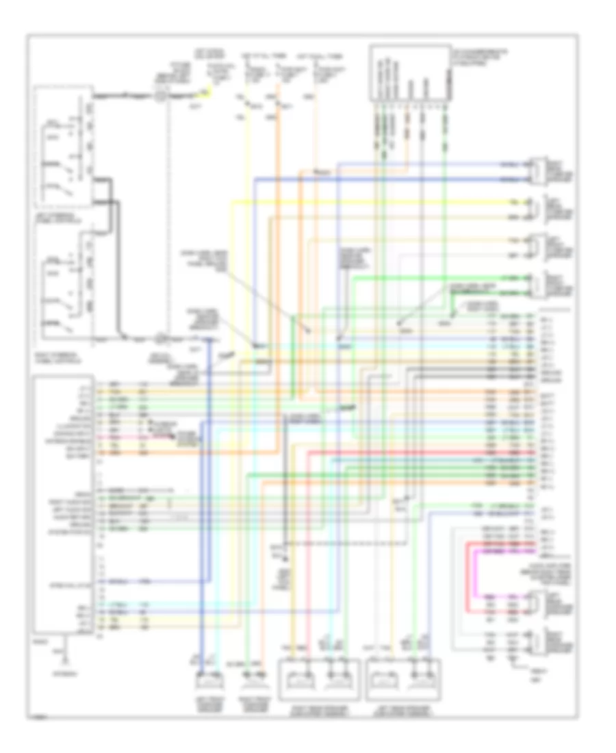
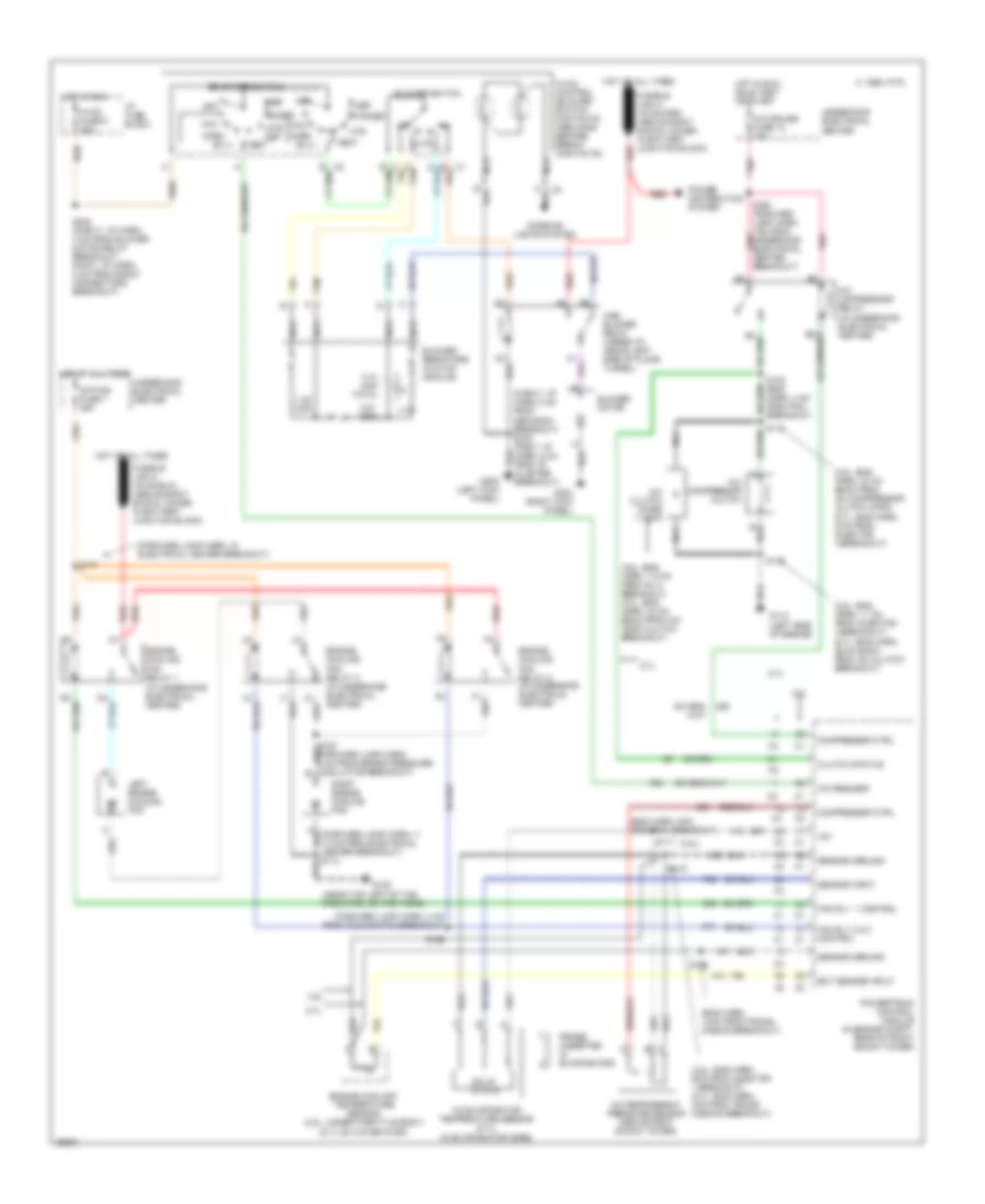
5.7L (VIN P), Электросхема коробки передач АКПП, A/T для Pontiac Firebird 1997
5.7L (VIN P), Электросхема коробки передач АКПП, A/T для Pontiac Firebird 1997 - Список элементов:
- (1996 chevy)
- (1996 pontiac)
- (1997 all)
- 1-2 shift sol
- 1-2 shift solenoid
- 2-3 shift sol
- 2-3 shift solenoid
- 3-2 ctrl solenoid
- 3-2 downshift sol
- 5v reference
- A/t fluid pressure manual valve position switch
- Automatic transmission (4l60-e)
- Battery in
- Body control module, brake switch assembly, daytime running lights module & instrument cluster
- Brake switch assembly (on brake pedal bracket)
- Brake switch input
- Conn a
- Conn b
- Conn c
- Conn d
- D13
- Data link connector (left side of dash)
- Ect sens input
- Egr vacuum control signal solenoid valve (1996 only)
- Eng sensor fuse 10 20a
- Engine coolant temperature sensor (front of engine, on water pump)
- Field service request
- Fuel pump relay
- G110 (front of left cylinder head)
- G120 (right side of engine above starter)
- Gages fuse 9 10a
- Hot at all times
- Hot in run, bulb test or start
- I/p fuse block
- Ignition in
- Instrument cluster
- Malfunction indicator lamp
- Mass air flow sensor & heated oxygen sensors
- Mil control
- Park/neutral in
- Pcm bat fuse 3 15a
- Pcm ground
- Pcm ign fuse 13 10a
- Pcs hi
- Pcs lo
- Pnk
- Pnk auxiliary accessory wire (1996 only)
- Powertrain control module (pcm) (in engine compt, behind right strut tower)
- Press control solenoid
- Range signal "a"
- Range signal "b"
- Range signal "c"
- Red
- Rev
- S104
- S106
- S110
- S122 (engine harn, 25 cm from pcm breakout)
- S132
- S206
- S215
- S234 (i/p harn, main branch approx 16cm from theft deter relay breakout at right side of dash)
- S270 (forward lamp harn, 4 cm from ecbm break-out)
- Sensor return
- Serial data
- Shift interlock system & hatch release circuit
- Tan
- Tcc pwm sol
- Tcc pwm solenoid
- Tcc sol
- Tcc solenoid
- Throttle position sensor (mounted to side of throttle body)
- Tp sens input
- Trans fluid temp sensor
- Trans temp sig in
- Transmission range switch (base of gear selector lever)
- Underhood electrical center
- Vehicle speed sensor (left rear of transmission)
- Vss hi
- Vss lo
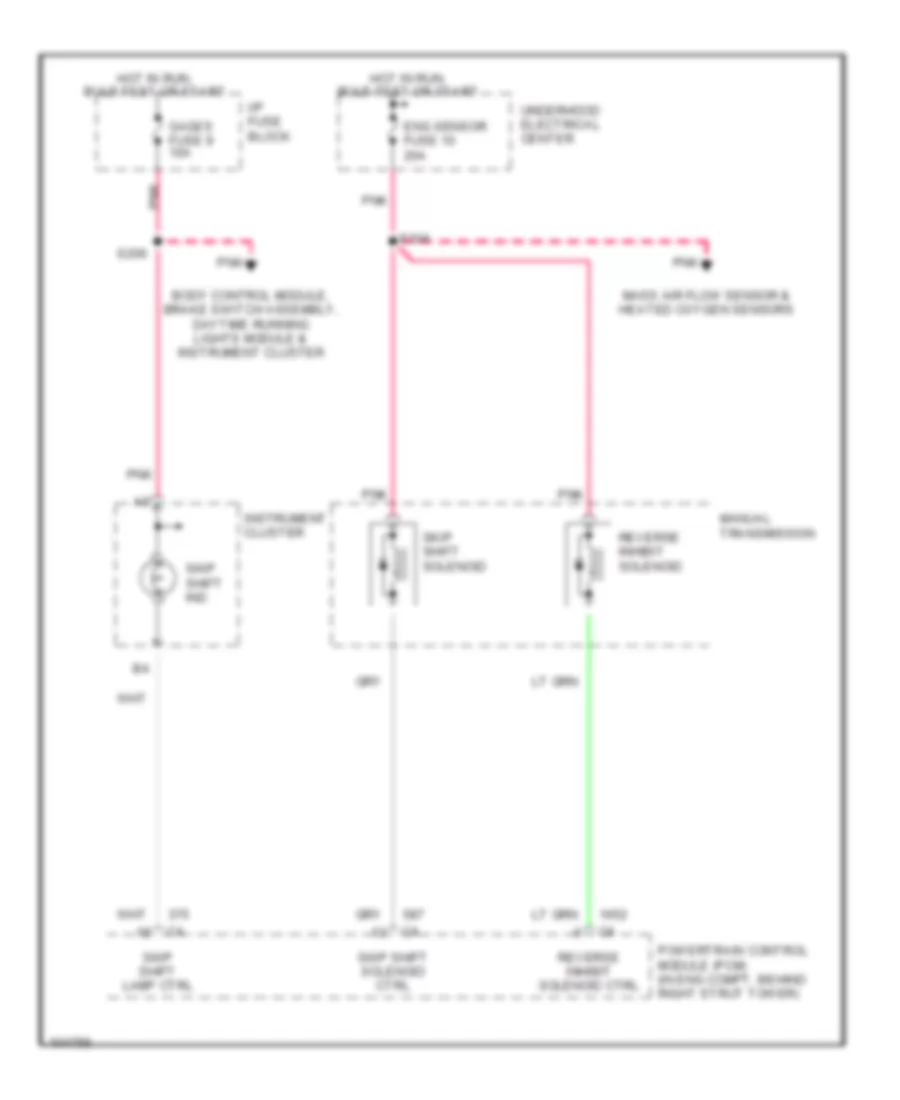
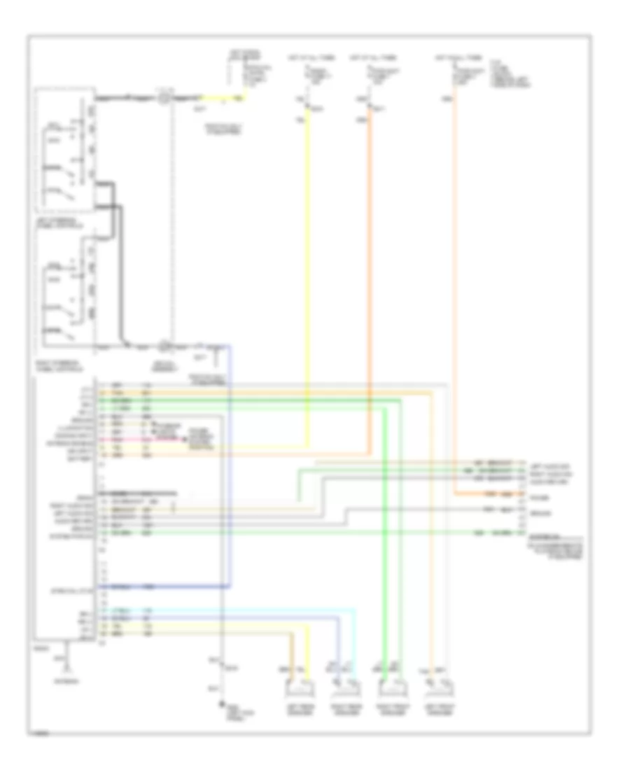
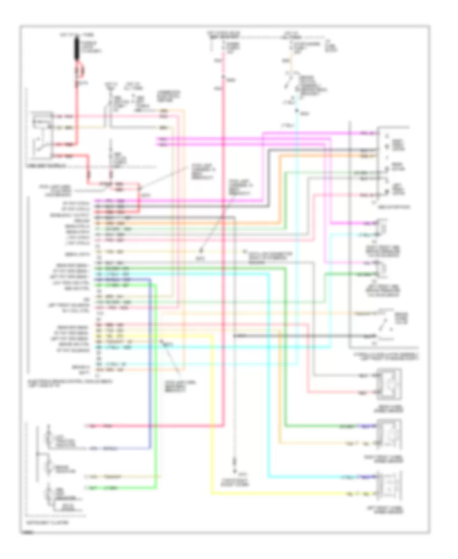
5.7L (VIN P), Электросхема коробки передач АКПП, M/T для Pontiac Firebird 1997
5.7L (VIN P), Электросхема коробки передач АКПП, M/T для Pontiac Firebird 1997 - Список элементов:
- Body control module, brake switch assembly, daytime running lights module & instrument cluster
- Eng sensor fuse 10 20a
- Gages fuse 9 10a
- Hot in run, bulb test or start
- I/p fuse block
- Instrument cluster
- Manual transmission
- Mass air flow sensor & heated oxygen sensors
- Pnk
- Powertrain control module (pcm) (in eng compt, behind right strut tower)
- Reverse inhibit solenoid
- Reverse inhibit solenoid ctrl
- S104
- S206
- Skip shift ind
- Skip shift lamp ctrl
- Skip shift solenoid
- Skip shift solenoid ctrl
- Underhood electrical center
АНТЕННА ПИТАНИЯ
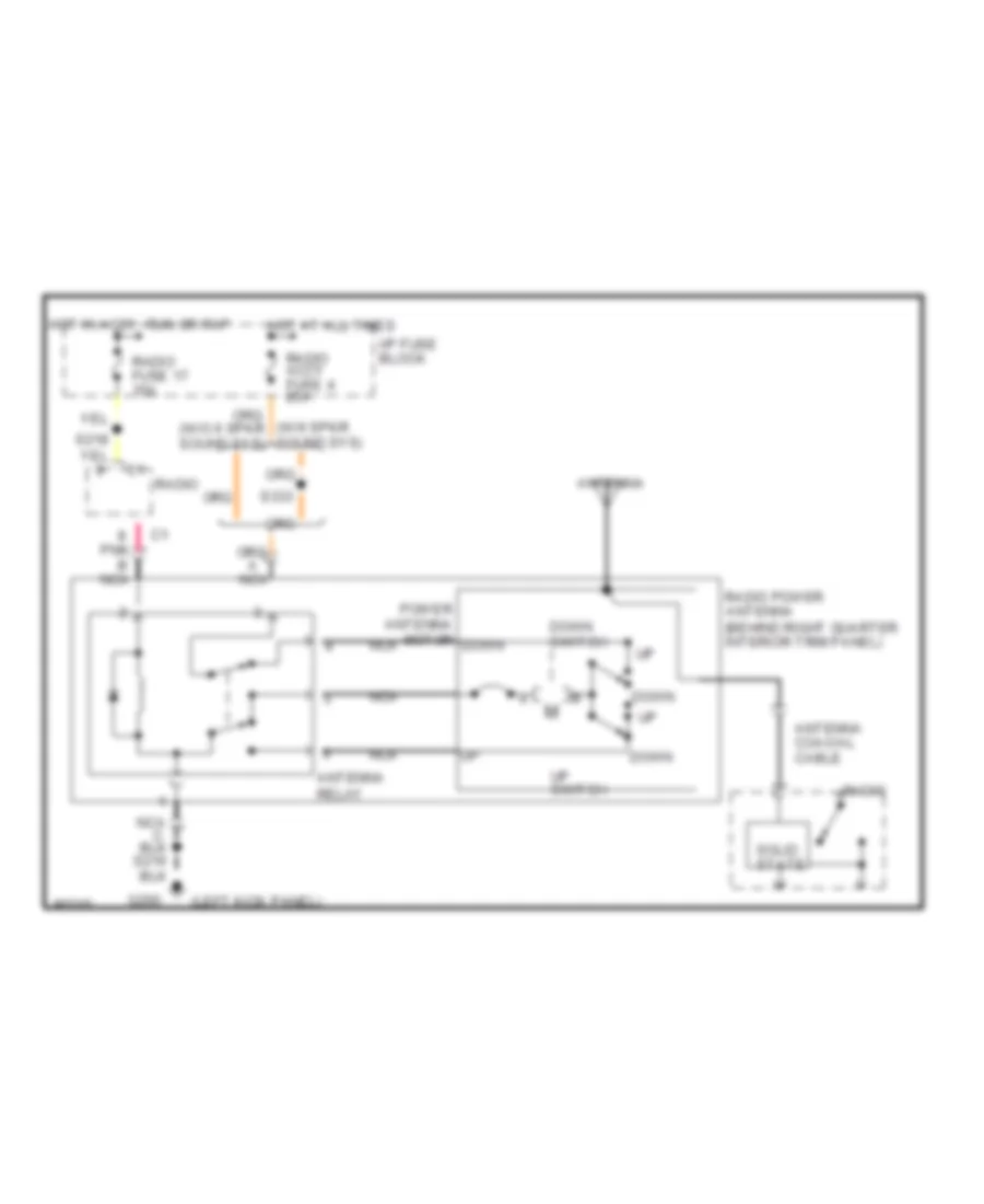
Электросхема антенны для Pontiac Firebird 1997
Электросхема антенны для Pontiac Firebird 1997 - Список элементов:
- (left kick panel)
- (w/6 spkr sound sys)
- Antenna
- Antenna coaxial cable
- Antenna relay
- Down
- Down switch
- G200
- Hot at all times
- Hot in accy, run or rap
- I/p fuse block
- Nca
- Pnk b nca
- Power antenna motor
- Radio
- Radio accy fuse 4 25a
- Radio fuse 17 15a
- Radio power antenna (behind right quarter interior trim panel)
- S216
- S333
- Solid state
- Up switch
БАГАЖНИК ЗАДНЯЯ ДВЕРЬ ЛЮЧОК ТОПЛИВНОГО БАКА
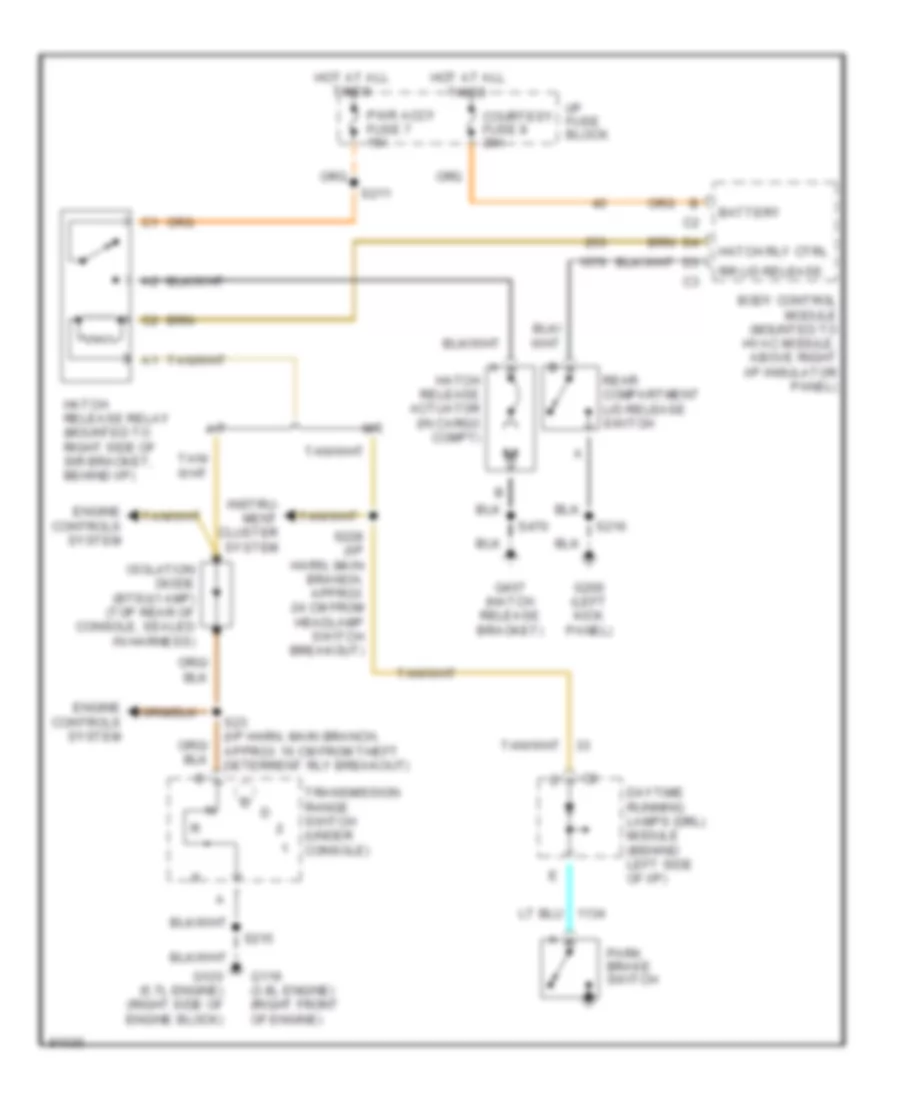
схема выпуска люка для Pontiac Firebird 1997
схема выпуска люка для Pontiac Firebird 1997 - Список элементов:
- A/t
- Battery
- Body control module (mounted to hvac module, above right i/p insulator panel)
- Courtesy fuse 8 20a
- Daytime running lamps (drl) module (behind left side of i/p)
- Engine controls system
- G119 (3.8l engine) (right front of engine)
- G120 (5.7l engine) (right side of engine block)
- G200 (left kick panel)
- G407 (hatch release bracket)
- Hatch release actuator (in cargo compt)
- Hatch release relay (mounted to right side of sir bracket, behind i/p)
- Hatch rly ctrl
- Hot at all times
- I/p fuse block
- Instru- ment cluster system
- Isolation diode (btsi)(1 amp) (top rear of console, sealed in harness)
- M/t
- Park brake switch
- Pwr accy fuse 7 15a
- Rear compartment lid release switch
- Rr lid release
- S211
- S215
- S216
- S228 (i/p harn, main branch, approx 24 cm from headlamp switch breakout)
- S23 (i/p harn, main branch, approx 16 cm from theft deterrent rly breakout)
- S470
- Transmission range switch (under console)
БЛОК ПРЕДОХРАНИТЕЛЕЙ И РЕЛЕ
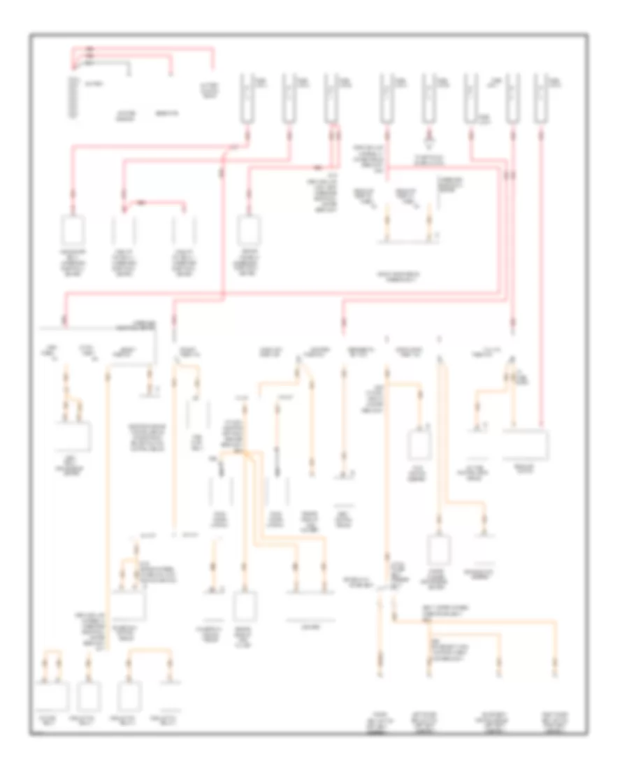
Электросхема блока предохранителей и реле (1 из 3) для Pontiac Firebird 1997
Электросхема блока предохранителей и реле (1 из 3) для Pontiac Firebird 1997 - Список элементов:
- (convenience
- (diagram 2 of 3)
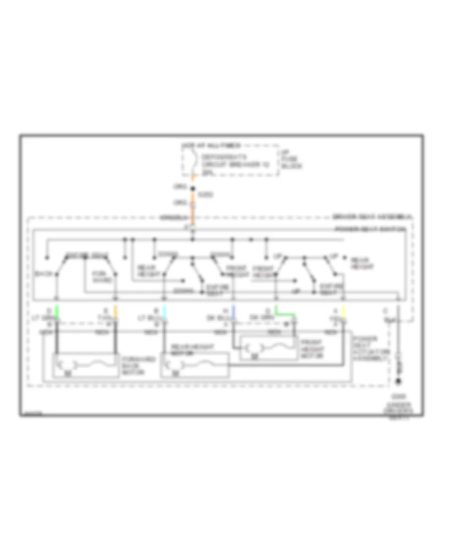
- (driver seat harn,
- (engine harness,
- (firebird
- (firebird only)
- (forward lamp
- (i/p harn,
- (left seat
- (right seat
- (seat jumper harness,
- (underhood
- 10a
- 14cm from lumbar
- 15a
- 20a
- 23cm from
- A/p fan
- Abs bat
- Abs/asr
- Air pump
- Amplifier
- Antenna
- Assembly
- Assembly)
- B12
- Battery
- Block
- Body
- Brake switch
- Brake/traction
- Breakout)
- Cb 12 30a
- Center
- Center)
- Changer
- Cluster
- Compact
- Control
- Control module
- Coolant
- Coolant fan
- Courtesy
- Cruise module
- Daytime
- Defog/seats
- Disc
- Door, lh
- Door, rh
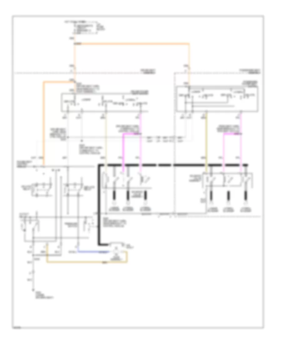
- Driver 6-way
- E11
- E12
- Electrical
- Electrical center
- Electronic brake
- Fan relay 1
- Flasher
- From main branch)
- Fuel
- Fuse
- Fuse 1 20a
- Fuse 3
- Fuse 3 15a
- Fuse 4
- Fuse 4 25a
- Fuse 5 20a
- Fuse 6 5a
- Fuse 7
- Fuse 8
- Fuse 8 20a
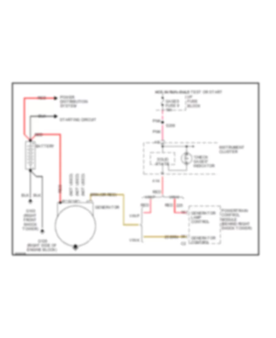
- Generator
- Harn, near
- Harness, at
- Harness, in
- Hazard
- Headlamp
- Headlt door module
- High blower
- Horn
- Hvac
- I/p
- Junction
- Left power
- Left rear
- Link a
- Link b
- Link c
- Link e
- Link f
- Link j
- Link k
- Link z
- Module
- Nca
- Near i/p
- Only)
- Or electronic
- Pcm bat
- Pcm branch, 20cm
- Player
- Power
- Power seat
- Powertrain
- Pump
- Pump breakout)
- Radio
- Radio accy
- Red
- Relay
- Relay 1
- Relay 2
- Relay 3
- Remote
- Right power
- Running lights
- S106
- S163
- S175
- S177
- S252
- S320
- S330
- S333
- Seat
- Seat switch
- Solenoid
- Speaker
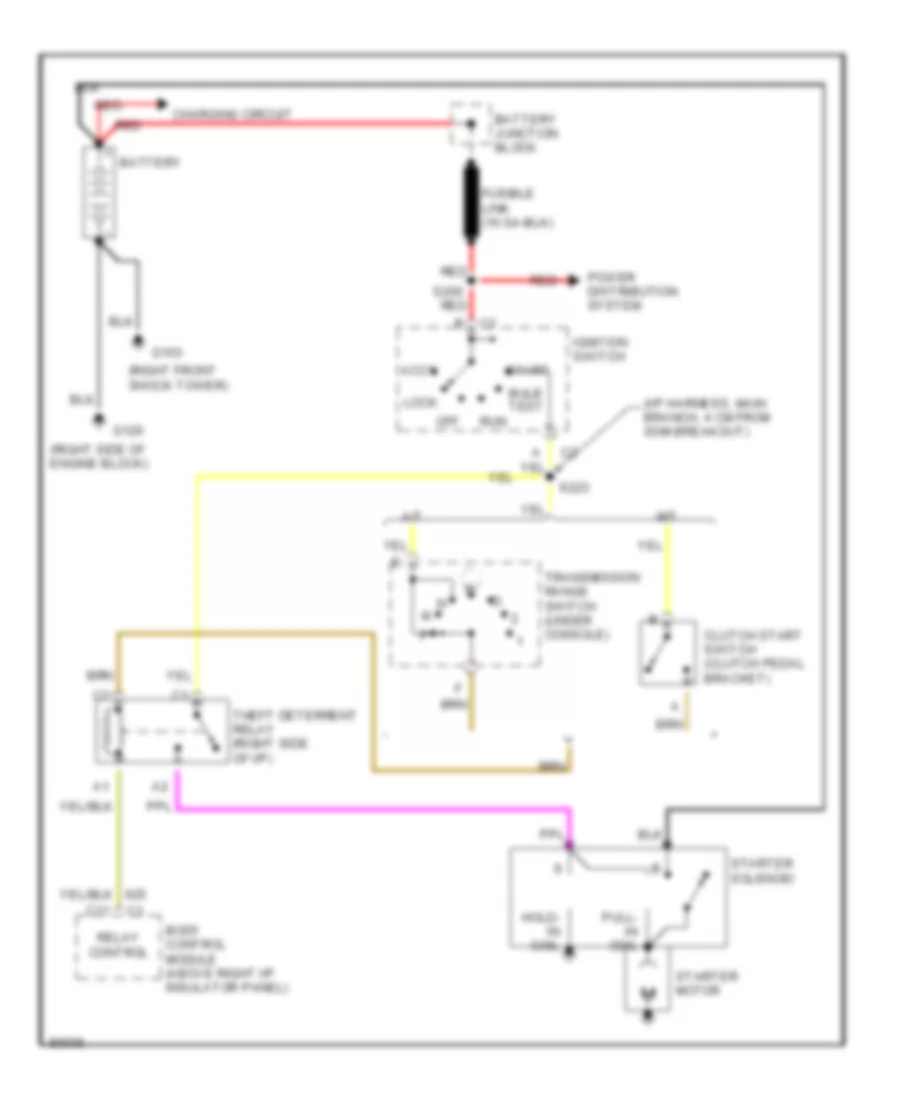
- Starter
- Stop/hazard
- Switch
- Tail lts
- Tcs/relay
- To ignition sw
- Ultima
- Under driver seat)
- Underhood
- V6 vin k
- V8 vin p
- W/ u27
- W/o u27
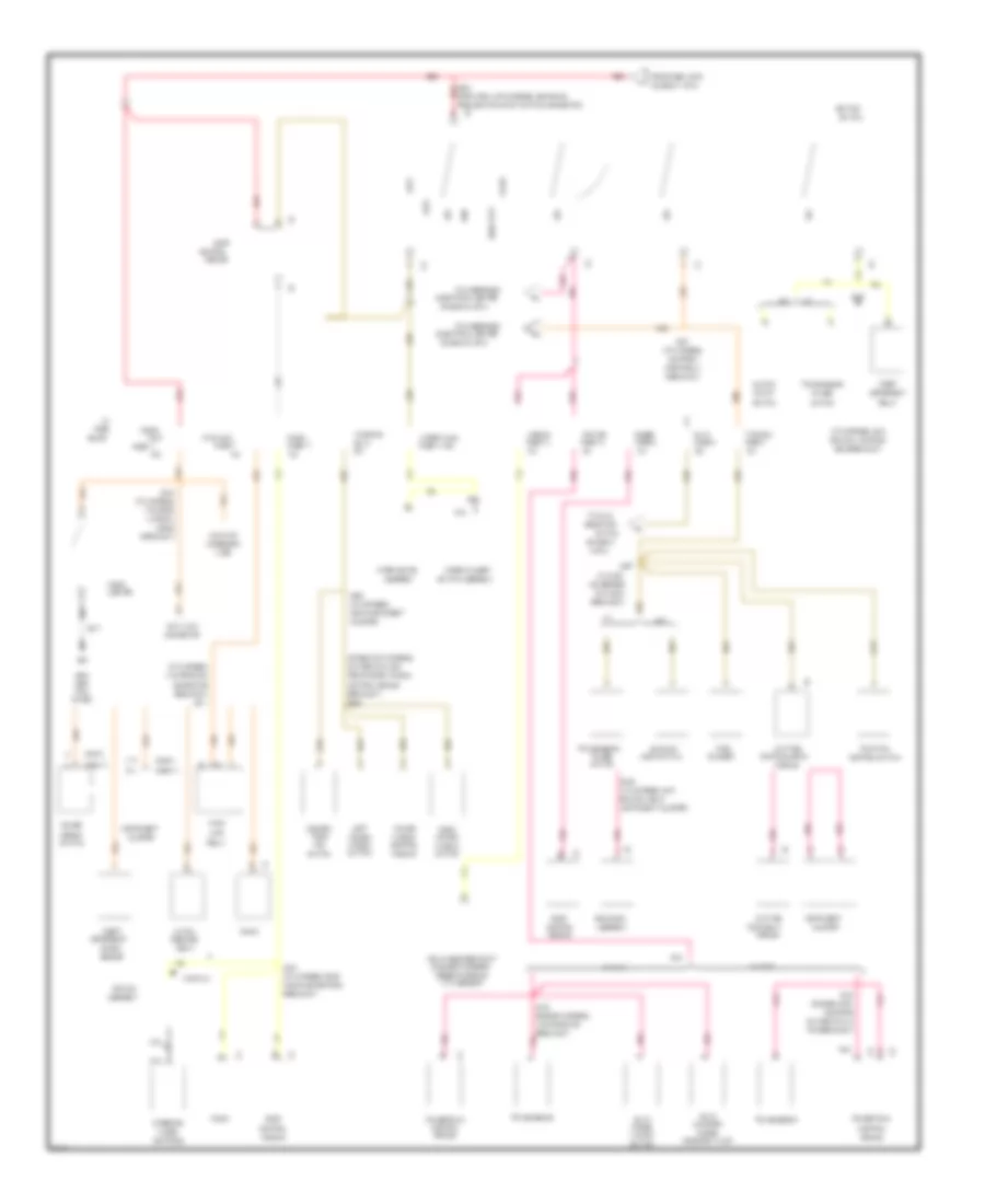
Электросхема блока предохранителей и реле (2 из 3) для Pontiac Firebird 1997
Электросхема блока предохранителей и реле (2 из 3) для Pontiac Firebird 1997 - Список элементов:
- (chevy)
- (cross car harness,
- (diagram
- (diagram 1 of 3)
- (diagram 3 of 3)
- (engine harn,
- (engine harness,
- (forward lamp harness, 35cm back
- (i/p harn,
- (i/p harness,
- (i/p harness, main
- (i/p harness, near
- (left
- (pont)
- 10a
- 11cm from dlc
- 15a
- 17cm from
- 19cm from
- 20a
- 21cm from pcm
- 25a
- 3 of 3)
- 30a
- 4cm before
- 5cm from
- A/t
- A13
- Accessory
- Accy
- Airbag
- Antenna
- Assembly
- Auxiliary
- Back-up
- Block
- Body
- Brake sw
- Branch, 4cm from
- Branch, near
- Breakout)
- Bulb test
- C14
- Cable
- Canister
- Cb 13
- Cigar
- Cigar/
- Cluster
- Cluster)
- Clutch
- Connector
- Control
- Control module
- Control switch
- Controls
- Conver-
- Data link
- Daytime
- Deterrent
- Diagnostic energy
- Dlc conn
- Electrical center
- Evap
- Flasher
- From fuse link e
- From ignition start switch connector)
- From power window
- Fuse
- Fuse 10
- Fuse 11
- Fuse 13
- Fuse 14 25a
- Fuse 17
- Fuse 2
- Fuse 6
- Fuse 7
- Fuse 9
- G200
- Gages
- Hatch
- Horn relay
- Hvac
- I/p
- Ignition
- Inflatable restraint
- Instrument
- Instrument cluster)
- Kick
- Lamp
- Left
- Light switch
- Lighter
- Lock
- M/t
- M/t a/t
- Main branch, 5cm
- Main branch, in
- Mirror
- Module
- Nca
- Near instrument
- Off
- Panel)
- Park
- Pcm breakout)
- Pcm ign
- Pnk
- Pontiac
- Power
- Powertrain
- Purge
- Pwr accy
- Radio
- Radio connectors
- Range
- Red
- Relay
- Release
- Reserve module
- Right
- Run
- Running lights
- Running lt
- S132
- S200
- S201
- S206
- S207
- S208
- S211
- S217
- S218
- S223
- S240
- S253
- Sdm breakout)
- Selector
- Sensor
- Shock
- Sir coil
- Solenoid valve
- Start
- Steering
- Switch
- Switch assembly
- Theft
- Tible
- To hvac
- To underhood
- Top
- Traction
- Transmission
- Turn
- Turn b-u
- V6 vin k
- V8 vin p
- Vacuum
- Wheel
- Window
- Windows
- Wiper motor
- Wiper/wash
- Wiper/washer
- Wire
- With sensor
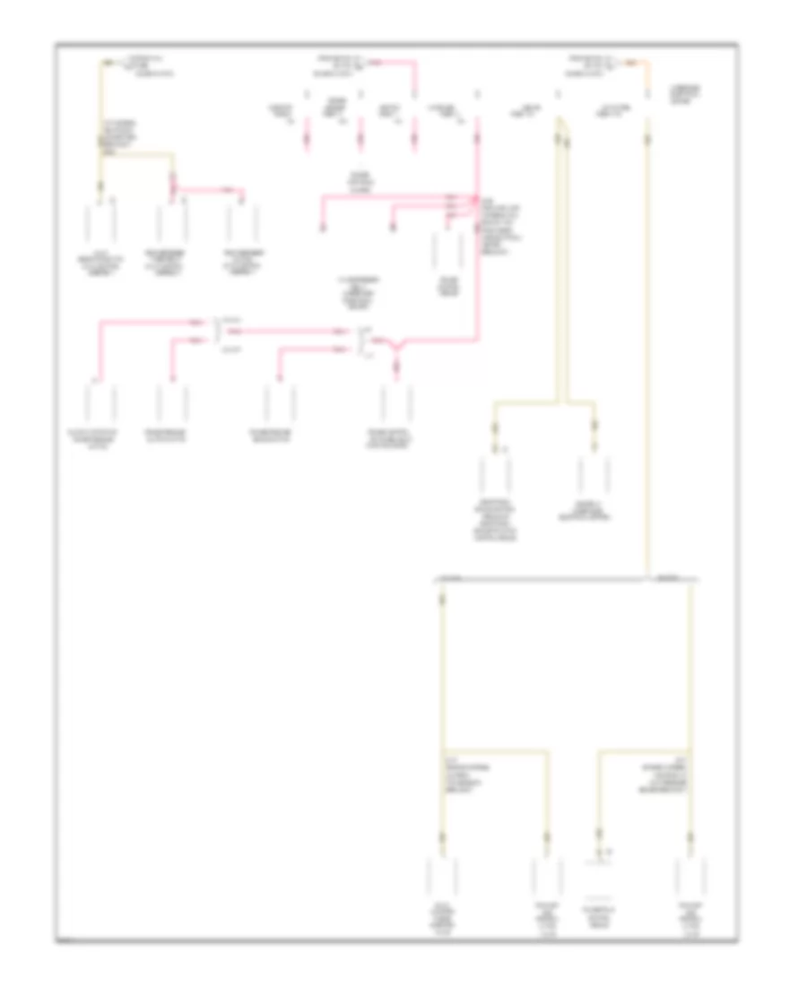
Электросхема блока предохранителей и реле (3 из 3) для Pontiac Firebird 1997
Электросхема блока предохранителей и реле (3 из 3) для Pontiac Firebird 1997 - Список элементов:
- (diagram 2 of 3)
- (engine harness,
- (forward lamp
- (hvac control
- (i/p harness,
- (underhood
- 10a
- 13cm from a/c
- 15a
- 20a
- 4cm from
- A/c compressor
- A/c-cruise
- A/t
- Abs ign
- Abs relay
- Actuators
- Assembly)
- B11
- Brake control
- Brake switch
- Brake/traction
- Branch, 7cm
- Breakout)
- Canister
- Center
- Center)
- Clutch anticipate
- Clutch switch
- Connectors
- Control
- Control module
- Controls
- Cruise
- Cruise control
- Cruise release
- Cruise release/
- Electrical
- Electrical center)
- Electronic
- Engine
- Evap
- Exhaust
- From hvac
- From ignition
- From under-
- Function lever)
- Fuse
- Fuse 1 5a
- Fuse 10
- Fuse 11
- Fuse 12
- Fuse 2 15a
- Fuse 9
- Gas
- Harness, main
- Hood elctrical
- Hvac
- Ignition
- Injector
- Lation
- Low pressure
- M/t
- Module
- Module or
- Near radio
- Pnk
- Powertrain
- Purge
- Rear defogger
- Recircu-
- Relay
- S127
- S165
- S248
- Selector switch
- Sensor
- Sensor breakout)
- Solenoid
- Switch
- Switches (multi-
- System
- Timer/relay
- Transmission
- Underhood
- V6 vin k
- V8 vin p
- Valve
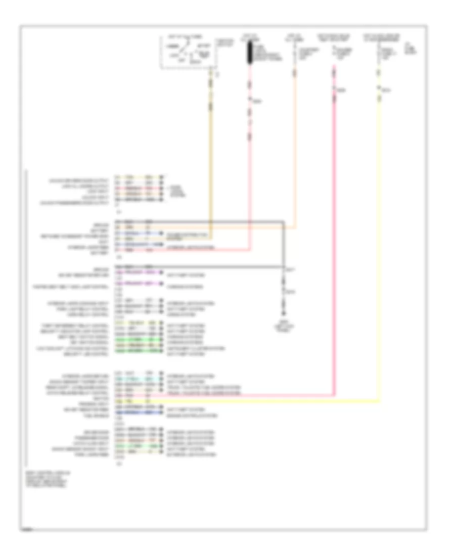
БЛОК УПРАВЛЕНИЯ КУЗОВОМ
Электросхема блока управления кузовом для Pontiac Firebird 1997
Электросхема блока управления кузовом для Pontiac Firebird 1997 - Список элементов:
- "low coolant" latching ind control
- Accy
- Anti-theft system
- Battery
- Body control module (mounted to hvac module, above right i/p insulator panel)
- Bulb test
- C10
- C11
- C12
- C13
- C14
- C15
- C16
- Courtesy fuse 8 20a
- D10
- D11
- D12
- D13
- D14
- D15
- D16
- Door locks system
- Driver door
- Engine controls system
- Exterior lights system
- Fasten seat belt indic lamp control
- Fuel enable
- Fuse link e (above right shock tower)
- G200 (left kick panel)
- Gauges fuse 9 10a
- Ground
- Hatch ajar input
- Hatch release relay control
- Horn relay control
- Horns system
- Hot at all times
- Hot in acc, run or w/ rap energized
- Hot in run, bulb test or start
- I/p fuse block
- Ign key resistor feed
- Ign key resistor return
- Ignition
- Ignition switch
- Instrument cluster system
- Interior lamps command input
- Interior lamps feed
- Interior lamps return
- Interior lights system
- Key ignition signal
- Lock
- Lock all doors output
- Lock input
- Off
- Park lamp relay control
- Park lamps feed
- Passenger door
- Pnk
- Power distribution system
- Program input
- Radio fuse 17 15a
- Rear compt lid release signal
- Red
- Retained accessory power (rap)
- Run
- S200
- S206
- S216
- S217
- S218
- Seat belt switch signal
- Security indicator lamp control
- Security led control
- Shock sensor "shock" input
- Shock sensor "tamper" input
- Start
- Tan
- Theft deterrent relay control
- Trunk, tailgate, fuel doors system
- Unlock driver's door output
- Unlock input
- Unlock passenger's door output
- Warning systems
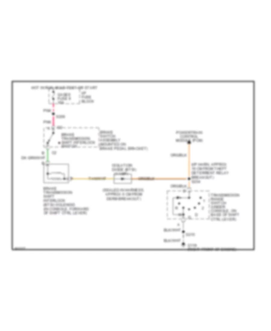
БЛОКИРОВКИ СЕЛЕКТОРА СТОЯНОЧНЫЙ ТОРМОЗ
Электросхема блокировки селектора для Pontiac Firebird 1997
Электросхема блокировки селектора для Pontiac Firebird 1997 - Список элементов:
- (1 amp)
- (i/p harn, approx 16 cm from theft deterrent relay breakout) s234
- (sealed in harness, approx 6 cm from derm breakout)
- Brake switch assembly (mounted on brake pedal bracket)
- Brake transmission shift interlock (btsi) solenoid (in console, forward of shift ctrl lever)
- Brake transmission shift interlock switch
- G119 (right front of engine)
- Gages fuse 9 10a
- Hot in run, bulb test or start
- I/p fuse block
- Isolation diode (btsi)
- Pnk
- Powertrain control module (pcm)
- S206
- S215
- Transmission range switch (under console, on base of shift ctrl lever)
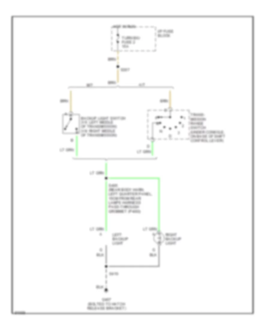
ВНЕШНЕЕ ОСВЕЩЕНИЕ
Электросхема заднего хода для Pontiac Firebird 1997
Электросхема заднего хода для Pontiac Firebird 1997 - Список элементов:
- A/t
- Backup light switch (v6: left middle of transmission) (v8: right middle of transmission)
- G407 (bolted to hatch release bracket)
- Hot in run
- I/p fuse block
- Left backup light
- M/t
- Right backup light
- S207
- S405 (rear body harn, left quarter panel, 15cm from rear lamps harness pass-through grommet (p400))
- S410
- Trans- mission range switch (under console, on base of shift control lever)
- Turn b/u fuse 2 15a
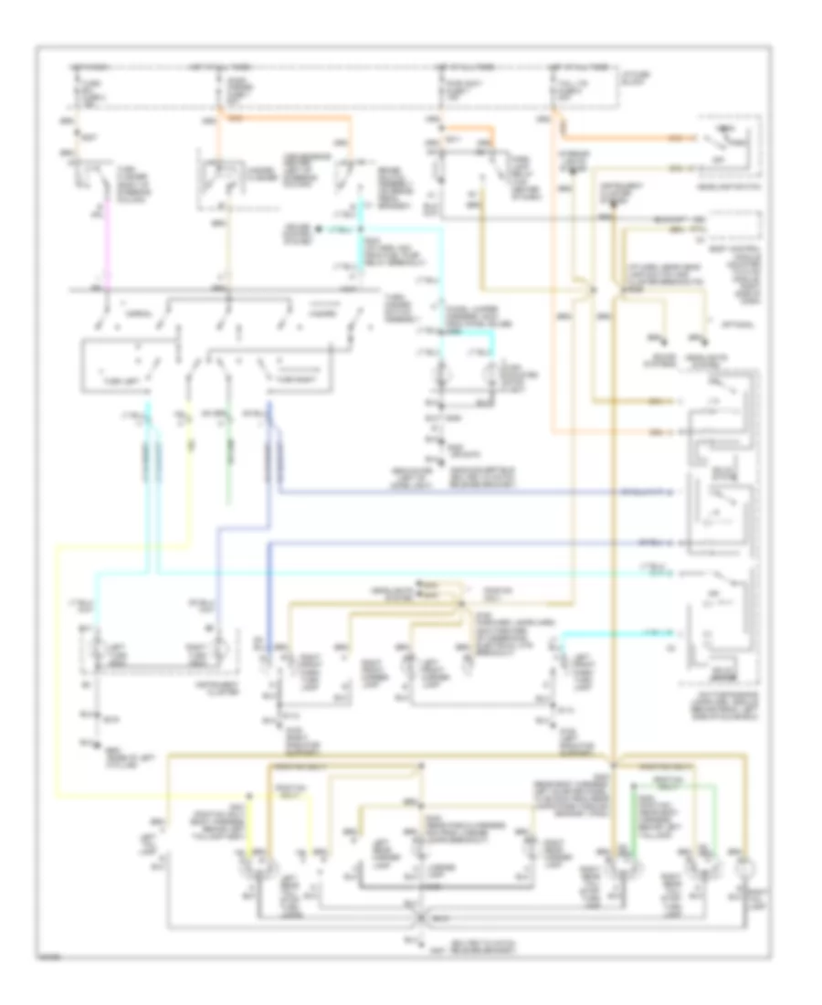
Электросхема внешнего освещения для Pontiac Firebird 1997
Электросхема внешнего освещения для Pontiac Firebird 1997 - Список элементов:
- (base of left
- (bolted to hatch release bracket)
- (chmsl jumper harness, 30cm from chmsl bulbs) s460
- (i/p harn, near head- lamp switch and cluster breakouts) s226
- (or s470)
- (pontiac only)
- A pillar)
- B14
- Body control module (mounted to hvac module, right side of dash)
- Brake switch assembly (on brake pedal bracket)
- Convenience center (left of steering column)
- Cruise control system
- D15
- Daytime running lamps (drl) module (behind radio, left side of glove box)
- G108 (left radiator support)
- G109 (right radiator support)
- G407
- G408-convertible (bolted to hatch release bracket)
- G900
- G902-coupe (left of dome light)
- Hazard
- Hazard flasher
- Head
- Headlamp switch
- Headlights system
- High mounted stop light
- Hot at all times
- Hot in run
- I/p fuse block
- Instrument cluster
- Instrument cluster system
- Interior lights system
- Left front marker lamp
- Left front park/ turn lamp
- Left rear marker lamp
- Left rear tail/ stop/ turn lamps
- Left tail lamp b
- Left turn indic
- License lamp
- Normal
- Off
- Optional
- Orn
- Park
- Park lamp relay (top center of dash)
- Pontiac only
- Pwr accy fuse 7 15a
- Right front marker lamp
- Right front park/ turn lamp
- Right rear marker lamp
- Right rear tail/ stop/ turn lamp
- Right tail lamp
- Right turn indic
- S112
- S113
- S150 (forward lamps harn, 22cm forward of underhood electrical ctr breakout)
- S207
- S211
- S216
- S243 (i/p harn, 8cm from fuel pump relay breakout)
- S400 (rear body harness, left quarter panel, 13 or 20cm from rear lamps pass-through grommet (p400))
- S401 (pontiac only) (body harness, behind left taillamp assy)
- S402 (pontiac) (rear body harness, behind left taillamp)
- S410
- S420
- S430
- S440 (rear fascia harness, 5cm from license lamps breakout)
- S450
- Solid state
- Sound systems
- Stop/ hazard fuse 1 20a
- Tail lts fuse 5 20a
- Turn b/u fuse 2 15a
- Turn flasher (right of steering column)
- Turn left
- Turn right
- Turn/ hazard switch assembly
ВНУТРЕННЕЕ ОСВЕЩЕНИЕ
Электросхема подсветки, Кабриолет для Pontiac Firebird 1997
Электросхема подсветки, Кабриолет для Pontiac Firebird 1997 - Список элементов:
- (hatch release bracket)
- (left kick panel)
- Body control module (bcm) (mounted on hvac module, above right i/p insulator panel)
- Courtesy fuse 8 20a
- Courtesy lamps power feed
- Courtesy lamps return
- D11
- D12
- D13
- G200
- G407
- Ground
- Hatch ajar input
- Hot at all times
- I/p compartment lamp
- I/p dimmer switch
- I/p fuse block
- Interior lamps command
- Left door jamb switch
- Left door open input
- Left rear courtesy lamp
- Power (battery)
- Rear compartment lamp
- Rear compartment lid ajar indication switch
- Rearview mirror
- Right door jamb switch
- Right door open input
- Right rear courtesy lamp
- S216
- S217
- S220
- S241 (i/p harn, approx 4 cm from antenna cable breakout)
- S247 (i/p harn approx 9 cm from fuel pump relay breakout)
- S317 (i/p harn, main branch)
- S470
Электросхема подсветки, Купе для Pontiac Firebird 1997
Электросхема подсветки, Купе для Pontiac Firebird 1997 - Список элементов:
- (hatch release bracket)
- (left kick panel)
- Body control module (bcm) (mounted on hvac module, above right i/p insulator panel)
- Courtesy fuse 8 20a
- Courtesy lamps power feed
- Courtesy lamps return
- D11
- D12
- D13
- Dome lamp
- G200
- G407
- Ground
- Hatch ajar input
- Hot at all times
- I/p compartment lamp
- I/p dimmer switch
- I/p fuse block
- Interior lamps command
- Left door jamb switch
- Left door open input
- Nca
- Power (battery)
- Rear compartment lid ajar indication switch
- Rearview mirror
- Right door jamb switch
- Right door open input
- S216
- S217
- S220
- S241 (i/p harn, 4 cm from antenna cable breakout)
- S247 (i/p harn, approx 9 cm from fuel pump relay breakout)
Электросхема подсветки приборов для Pontiac Firebird 1997
Электросхема подсветки приборов для Pontiac Firebird 1997 - Список элементов:
- (6)
- A/t
- Ashtray lamp
- Convertible top switch
- Courtesy lamps circuit
- D nca
- Daytime running lights (drl) module (mounted behind radio and hvac controls, left of i/p compartment) (w/drl)
- Exterior lights system
- Fog light switch
- G120 (right front of engine)
- G200 (left kick panel)
- G407 (hatch release bracket)
- Gauges fuse 9 10a
- Head
- Headlight switch
- Hot at all times
- Hot in run, bulb test or start
- Hvac control assembly
- I/p dimmer fuse 16 5a
- I/p dimmer switch
- I/p fuse block
- Instrument cluster
- Left door illumination lamp
- M/t
- Max
- Min
- Nca
- Off
- Park
- Park lights relay
- Pnk
- Prndl illumination lamp
- Radio
- Relay breakout) s224
- Right door illumination lamp
- Right steering wheel radio controls
- S206
- S215
- S216
- S217
- S220
- S226 (i/p harn, in headlamp switch breakout)
- S260 (cross car harn, behind left side of i/p)
- S470
- Sir coil assembly
- Solid state
- Tail lts fuse 5 20a
- Traction control switch
ЗАЗЕМЛЕНИЕ ПОДКЛЮЧЕНИЕ МАССЫ
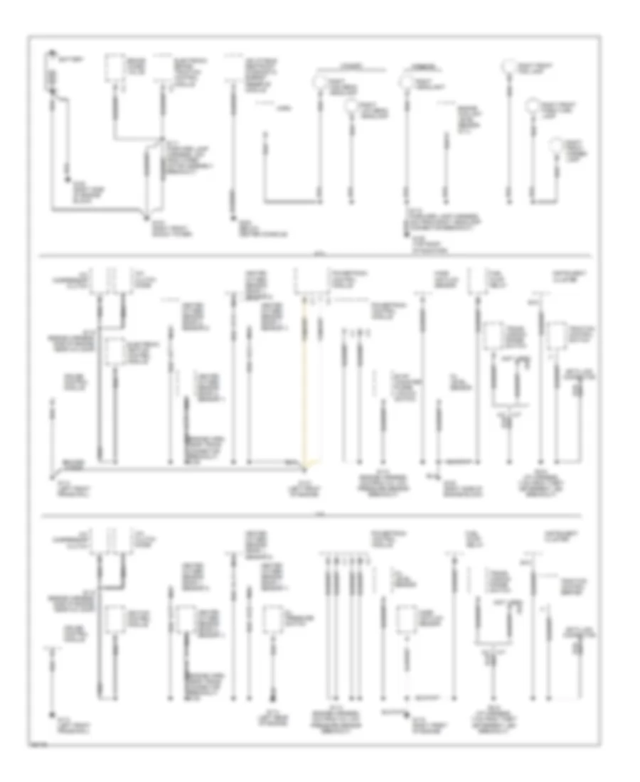
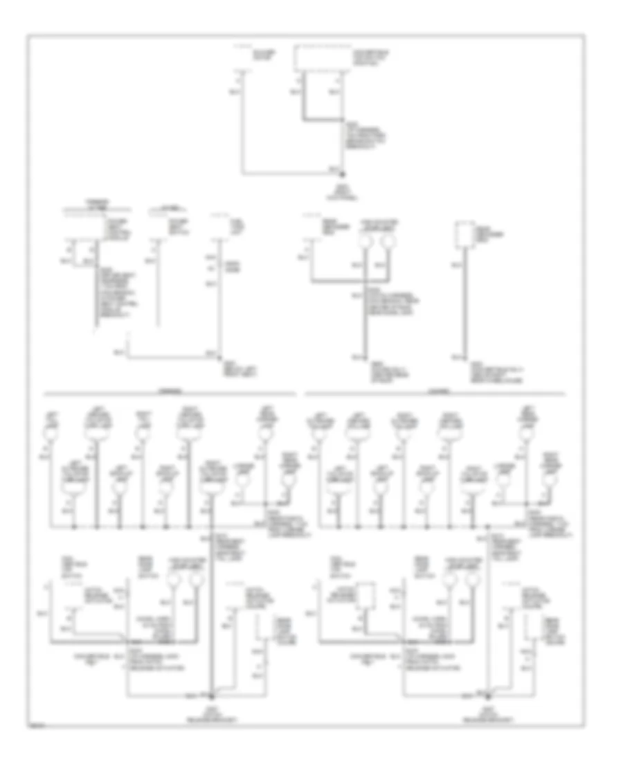
Электросхема подключение массы заземления (1 из 3) для Pontiac Firebird 1997
Электросхема подключение массы заземления (1 из 3) для Pontiac Firebird 1997 - Список элементов:
- (not used) a
- 3.8l
- 5.7l
- A/c clutch diode
- A/c compressor clutch
- A/t
- B15
- Battery
- Braided strap
- Brake combo valve
- Camaro
- Cruise control module
- Electronic brake/ traction control module
- Electronic ignition control module
- Engine coolant level sensor (5.7l)
- Evap canister purge vacuum switch
- Firebird
- Fuel pump relay
- G103 (right front shock tower)
- G109 (top right of radiator)
- G110 (left front of engine)
- G113 (left front frame rail)
- G114 (left rear of engine)
- G119 (right front of engine)
- G120 (right side of engine block)
- G302 (below center console)
- Heated oxygen sensor (bank 1, sensor 1)
- Heated oxygen sensor (bank 1, sensor 2)
- Heated oxygen sensor (bank 1, sensor 3)
- Heated oxygen sensor (bank 2, sensor 1)
- Heated oxygen sensor (bank 2, sensor 2)
- Horn
- Ignition control module
- Inflatable restraint diagnostic energy reserve module
- Instrument cluster
- Mass air flow sensor
- Nca
- Oil level sensor
- Oil pressure switch
- Powertrain control module
- Right front fog lamp
- Right front marker lamp
- Right front park/turn lamp
- Right headlight
- Right high beam headlamp
- Right low beam headlamp
- S110 (engine harness, 4cm from a/c low pressure sensor breakout)
- S111 (forward lamp harness, 3cm from wiper motor assembly breakout)
- S112 (forward lamp harness, 4cm from right headlamp connector breakout)
- S115 (engine harness, side of engine, near a/c comp)
- S215 (i/p harness, 11cm from theft deterrent led breakout)
- Traction control switch
- Traction control switch switch
- Trans- mission range switch
Электросхема подключение массы заземления (2 из 3) для Pontiac Firebird 1997
Электросхема подключение массы заземления (2 из 3) для Pontiac Firebird 1997 - Список элементов:
- A (firebird) (camaro)
- A/t
- Amplifier (firebird w/ uw2)
- Ashtray lamp
- Auxiliary accessory wire taped to i/p harness
- Body control module
- Camaro
- Cigar lighter
- Coolant fan #3 relay
- Courtesy/ reading lamps
- Data link connector
- Daytime running lights module
- Daytime running lights relay (pontaic)
- Firebird
- Fog light switch
- G108 (top left of radiator)
- G200 (left kick panel)
- Hatch release switch
- Headlamp doors module
- Headlamp switch
- High blower relay
- Hvac control assembly
- Hvac control assembly (firebird)
- Hvac illumination lamps
- I/p compartment lamp
- I/p dimmer switch
- Ignition key alarm switch
- Instrument cluster
- Left cooling fan
- Left door illumination lamp
- Left front fog lamp
- Left front marker lamp
- Left front park/turn lamp
- Left headlamp
- Left high beam headlamp
- Left low beam headlamp
- Left power door lock switch
- Left power window switch
- M/t
- Nca
- Power mirror switch
- Prndl illumination lamp
- Radio
- Radio power antenna
- Rear defogger relay/ timer
- Rear defogger switch
- Rearview mirror
- Right coolant fan
- Right door illumination lamp
- Right power door lock switch
- S113 (forward lamp harn, 7cm from underhood electrical center breakout)
- S216 (i/p harness, near instrument cluster)
- S217 (i/p harness, 18 cm from bcm breakout)
- Seat belt switch
- Secondary air inject- ion bleed solenoid valve (5.7l)
- Secondary air inject- ion pump assembly (5.7l)
- Security indicator led
- Sir coil assembly
- Steering wheel controls, radio (firebird w/ uk3)
- Theft deterrent shock sensor
- W/ power accy
- W/o power accy
- Washer pump motor
- Wiper motor assembly
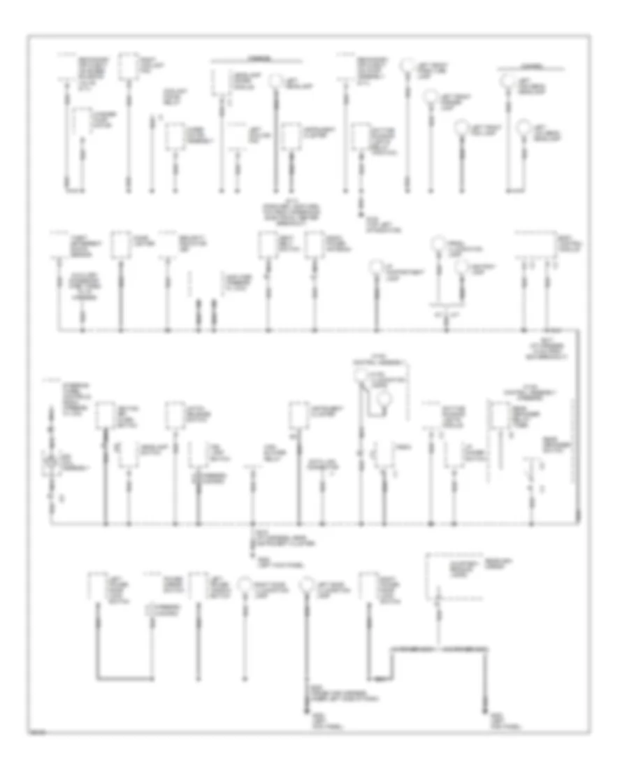
Электросхема подключение массы заземления (3 из 3) для Pontiac Firebird 1997
Электросхема подключение массы заземления (3 из 3) для Pontiac Firebird 1997 - Список элементов:
- (chmsl harn, 24 cm from chmsl bulbs) s450
- Blower motor
- C405a
- C405b
- Camaro
- Con- vertible top switch
- Convertible only
- Convertible top switch (pontiac)
- Firebird
- Firebird w/ aq9
- Fuel tank unit
- G203 (right kick panel)
- G300 (below left front seat)
- G403 (convertible only) (above right rear wheelhouse)
- G407 (hatch release bracket)
- G909 (coupe only) (center rear of roof)
- Hatch release actuator
- Hatch release actuator (coupe)
- High mounted stop light
- Left back-up lamp
- Left inboard tail/stop turn lamp
- Left inboard taillamp
- Left outboard tail/stop turn lamp
- Left outboard taillamp
- Left rear marker lamp
- Left tail- lamp
- Left tail/stop turn lamp
- License lamp
- Nca
- Power seat control module
- Power seat switch
- Rear defogger grid
- Rear dome lamp switch
- Rear dome lamp switch (coupe)
- Right back-up lamp
- Right inboard tail/stop turn lamp
- Right inboard taillamp
- Right outboard tail/stop turn lamp
- Right outboard taillamp
- Right rear marker lamp
- Right tail- lamp
- Right tail/stop turn lamp
- S232 (i/p harness, 7cm from park brake switch breakout)
- S335 (driver seat hearness, 11cm from main branch, in power seat control module breakout)
- S410 (rear body harness, near right tail lamp)
- S420 (hatch harness, main branch, rear center of roof, near dome lamp)
- S430 (rear fascia harness, 11cm from license lamp breakout)
- S470 (i/p harness, 24cm from hatch release actuator)
- W/ ag1
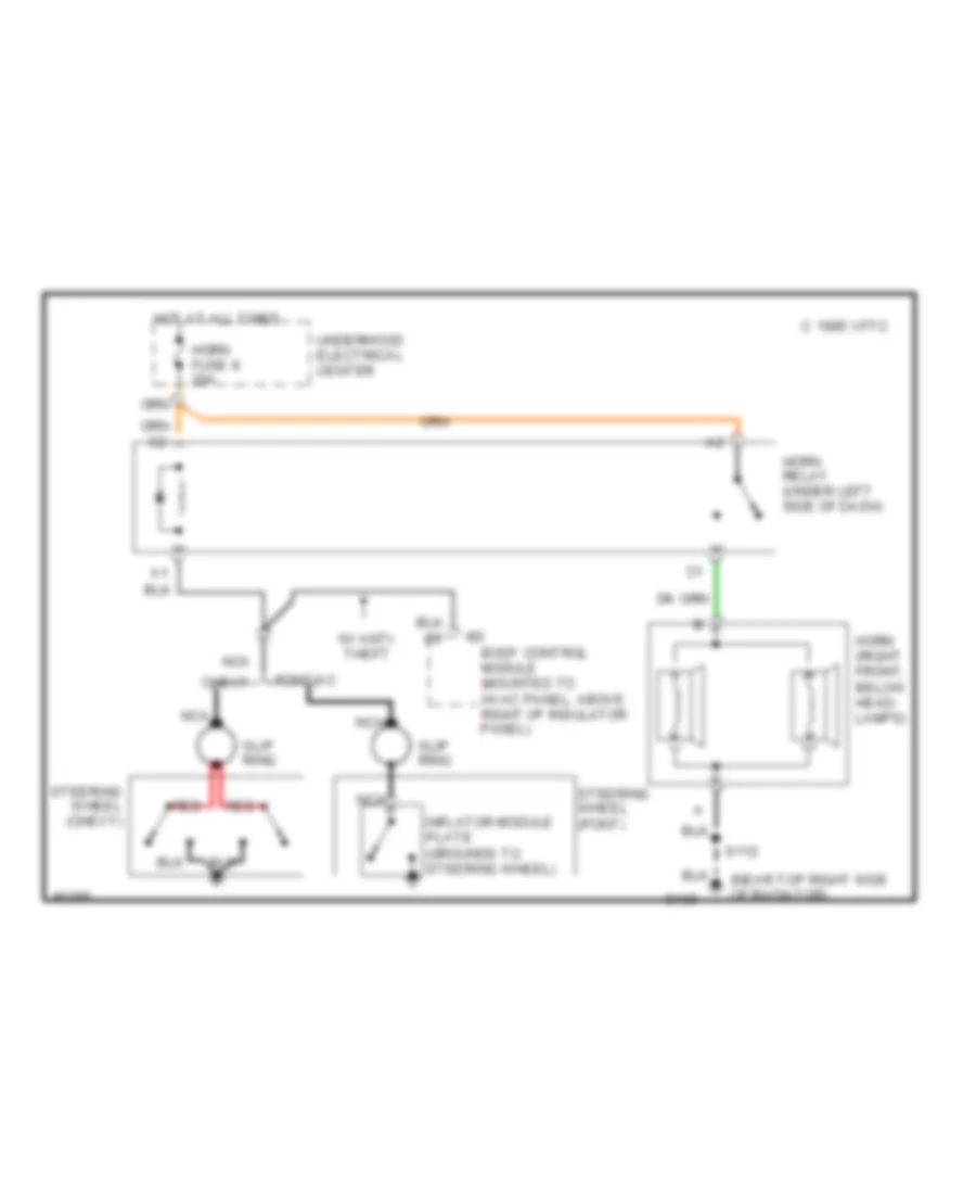
Звуковой сигнал Гудок
Электросхема звукового сигнал Гудка для Pontiac Firebird 1997
Электросхема звукового сигнал Гудка для Pontiac Firebird 1997 - Список элементов:
- (near top right side of radiator)
- Body control module (mounted to hvac panel, above right i/p insulator panel)
- C 1995 vftc
- Chevy
- G109
- Horn (right front, below head- lamps)
- Horn fuse 8 20a
- Horn relay (under left side of dash)
- Hot at all times
- Inflator module plate (grounds to steering wheel)
- Nca
- Orn
- Orn c2
- Pontiac
- Red
- S112
- Slip ring
- Steering wheel (chevy)
- Steering wheel (pont)
- Underhood electrical center
- W/ anti- theft
Магнитола Мультимедия
Электросхемы магнитолы, С усилитель для Pontiac Firebird 1997
Электросхемы магнитолы, С усилитель для Pontiac Firebird 1997 - Список элементов:
- (dash harn, near bcm breakout)
- (dash harn, near lr speaker breakout)
- (dash harn, near right kick panel ground) s307
- (dash harn, near rr speaker breakout)
- (dash harn, right dash)
- (or red)
- (or tan)
- 1998-01
- Antenna
- Antenna enable
- Audio amplifier (behind right rear quarter inner trim panel)
- Audio return
- Bare
- Batt
- Battery
- C217
- Cd changer-remote playback device (if equipped)
- Dimming input
- Drain
- E10
- E11
- E12
- E13
- E14
- E15
- E16
- F10
- F11
- F12
- F13
- F14
- F15
- F16
- G200 (left kick panel)
- Ground
- Hot at all times
- Hot in run, acc or rap
- I/p fuse block (behind left side of dash)
- Ign input
- Illumination
- Interior lights system
- Left audio sig
- Left front midrange speaker
- Left front tweeter speaker
- Left rear midrange speaker
- Left rear speaker subwoofer assembly
- Left rear tweeter speaker
- Left steering wheel controls
- Lf (+)
- Lf (-)
- Lr (+)
- Lr (-)
- Nca
- Pnk
- Power
- Power antenna system
- Pwr accy fuse 4 25a
- Pwr accy fuse 7 15a
- Radio
- Radio fuse 17 15a
- Red
- Rf (+)
- Rf (-)
- Rf(-)
- Right audio sig
- Right front midrange speaker
- Right front tweeter speaker
- Right rear midrange speaker
- Right rear speaker subwoofer assembly
- Right rear tweeter speaker
- Right steering wheel controls
- Rr (+)
- Rr (-)
- S211
- S216
- S217
- S218
- S300
- S301
- S302
- S303
- S304
- S305
- S306
- S333
- Sir coil assembly
- Stg whl cntrl fuse 3 1a
- Strg whl ctlr
- Sw1
- Sw2
- Sw3
- Sw4
- Sw5
- Sw6
- Sw7
- Sw8
- System on
- System pwr on
- Tan
Электросхемы магнитолы, без усилитель для Pontiac Firebird 1997
Электросхемы магнитолы, без усилитель для Pontiac Firebird 1997 - Список элементов:
- Antenna
- Antenna enable
- Audio return
- Bare
- Battery
- C217
- Cd changer-remote playback device (if equipped)
- Dimming input
- Drain
- G200 (left kick panel)
- Ground
- Hot at all times
- Hot in run, acc or rap
- I/p fuse block (behind left side of dash)
- Ign input
- Illumination
- Interior lights system
- Left audio sig
- Left front speaker
- Left rear speaker
- Left steering wheel controls
- Lf (+)
- Lf (-)
- Lr (+)
- Lr (-)
- Nca
- Pnk
- Pontiac only (if equipped)
- Power
- Power antenna system (pontiac)
- Pwr accy fuse 4 25a
- Pwr accy fuse 7 15a
- Radio
- Radio fuse 17 15a
- Rf (+)
- Rf(-)
- Right audio sig
- Right front speaker
- Right rear speaker
- Right steering wheel controls
- Rr (+)
- Rr (-)
- S211
- S216
- S218
- Sir coil assembly
- Stg whl cntrl fuse 3 1a
- Strg whl ctlr
- Sw1
- Sw2
- Sw3
- Sw4
- Sw5
- Sw6
- Sw7
- Sw8
- System on
- System pwr on
- Tan
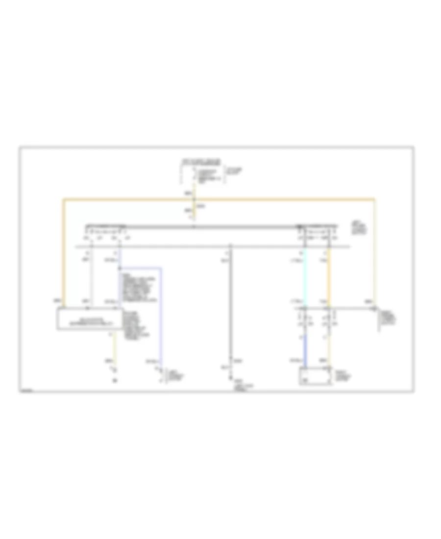
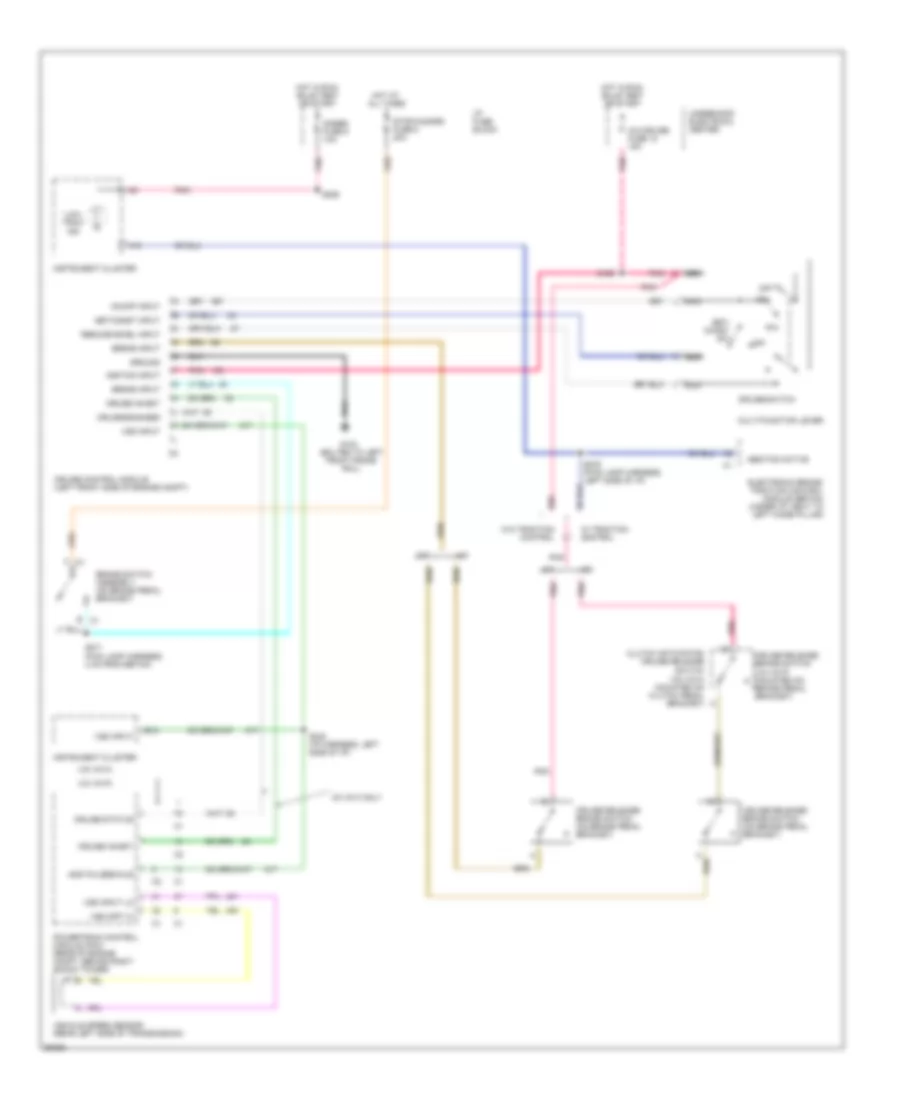
Подогрев стекол и зеркал
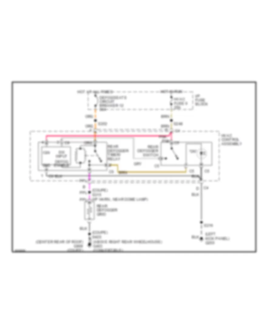
Электросхема подогрева стекол и зеркал для Pontiac Firebird 1997
Электросхема подогрева стекол и зеркал для Pontiac Firebird 1997 - Список элементов:
- "on"
- (above right rear wheelhouse) g403 (convertible)
- (coupe) s315 (i/p harn., near dome lamp)
- (coupe) s420
- (left kick panel) g200
- Defog enable
- Defog/seats circuit breaker 12 30a
- Gnd
- Hot at all times
- Hot in run
- Hvac control assembly
- Hvac fuse 6 20a
- I/p fuse block
- Ign
- Pnk
- Rear defogger grid
- Rear defogger switch
- Rear defogger timer/ relay
- S216
- S248
- S252
- Sw input
ПОДУШКИ БЕЗОПАСНОСТИ AIR BAG
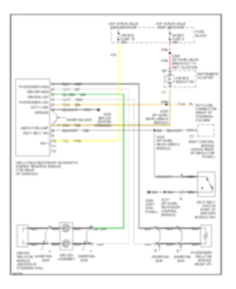
Электросхема подушек безопасности SRS AirBag для Pontiac Firebird 1997
Электросхема подушек безопасности SRS AirBag для Pontiac Firebird 1997 - Список элементов:
- Air bag fuse 10 15a
- Air bag indicator
- B nca
- Bar
- Body control module (above right i/p insulator panel)
- Breakout to inst cluster)
- C13
- Data line
- Data link connector (right of steering column)
- Driver high
- Driver inflator module (center of steering whl)
- Driver low
- Fuse block
- G200 (left kick panel)
- G302 (below center console)
- Gages fuse 9 10a
- Ground
- Hot in run, bulb test or start
- Ign 1
- Indicator lamp
- Inflatable restraint diagnostic energy reserve module (top rear of console)
- Instrument cluster
- Nca
- Passenger high
- Passenger inflator module (right i/p)
- Passenger low
- Pnk
- S206 (i/p harn, near pnk
- S217 (i/p harn, near body control module)
- S222 (i/p harn, near airbag module)
- S225 (i/p harn, near airbag module)
- Seat belt sig
- Seat belt switch (part of driver's buckle sw)
- Shorting
- Shorting bar
- Sir coil assembly
- Tan
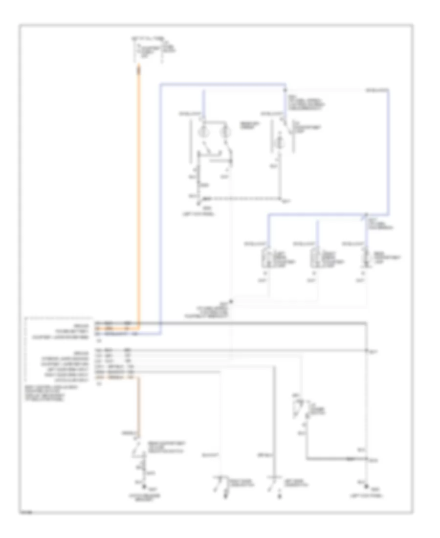
ПРЕДУПРЕЖДАЮЩИЕ СИСТЕМЫ
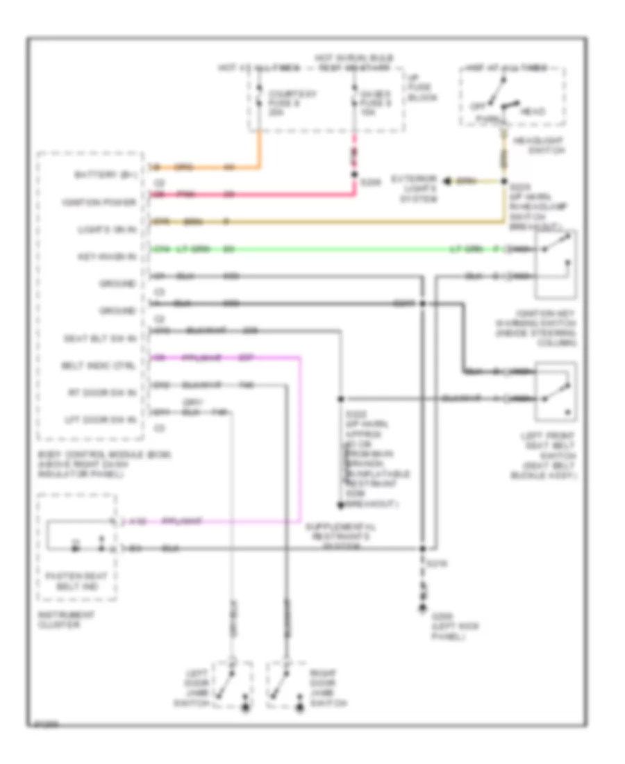
Электросхема предупреждающей системы для Pontiac Firebird 1997
Электросхема предупреждающей системы для Pontiac Firebird 1997 - Список элементов:
- A12
- Battery (b+)
- Belt indic ctrl
- Body control module (bcm) (above right dash insulator panel)
- C13
- C14
- Courtesy fuse 8 20a
- D11
- D12
- D15
- Exterior lights system
- Fasten seat belt ind
- G200 (left kick panel)
- Gages fuse 9 10a
- Ground
- Head
- Headlight switch
- Hot at all times
- Hot in run, bulb test or start
- I/p fuse block
- Ignition key warning switch (inside steering column)
- Ignition power
- Instrument cluster
- Key-in-ign in
- Left door jamb switch
- Left front seat belt switch (seat belt buckle assy)
- Lft door sw in
- Lights on in
- Nca
- Off
- Park
- Pnk
- Right door jamb switch
- Rt door sw in
- S206
- S216
- S217
- S222 (i/p harn, approx 83 cm from main branch, in inflatable restraint sdm breakout)
- S226 (i/p harn, in headlamp switch breakout)
- Seat blt sw in
ПРИБОРНАЯ ПАНЕЛЬ
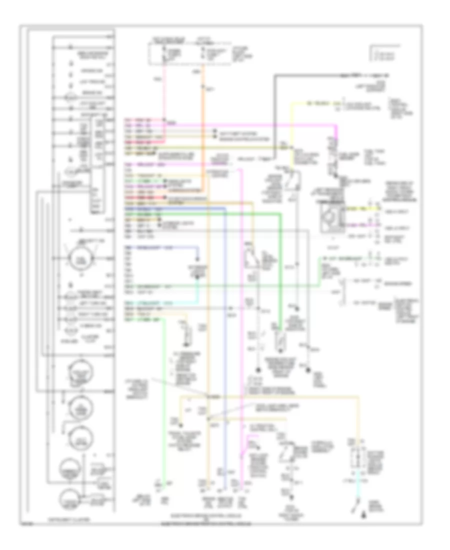
Электросхема панели приборов для Pontiac Firebird 1997
Электросхема панели приборов для Pontiac Firebird 1997 - Список элементов:
- (6 bulbs)
- (below left side of i/p)
- (fwd lamp harn, near ebtcm breakout)
- (i/p harn, 24 cm from headlamp switch breakout)
- (left rear side of transmission) vehicle speed sensor
- (rear top center of engine)
- (rearward of right front shock tower) powertrain control module
- (right side of engine) (right front of engine)
- (top of right shock tower)
- (top right side of engine)
- (top right side of radiator)
- A10
- A11
- A12
- A13
- A14
- A15
- A16
- A17
- Abs fail
- Abs inop ind
- Abs/tcs active output
- Air bag ind
- Anti-lock brakes system (traction control switch)
- Anti-theft system
- B10
- B11
- B12
- B13
- B14
- B15
- B16
- B17
- Bat
- Body control module (right side of i/p)
- Brake
- Brake combo valve
- Brake ind
- C15
- Check gages ind
- Clnt
- Cluster illum
- Coolant temp gage
- Daytime running lights module (behind radio)
- Electronic brake control module or electronic brake/traction control module
- Electronic ignition control module (left front of engine)
- Engine controls system
- Engine coolant level sensor (top right side of radiator)
- Engine coolant temperature gage sensor (front of engine)
- Engine speed
- Exterior lights system
- Fasten seat belt ind
- Fuel gage
- Fuel gage sender
- Fuel tank unit (top of fuel tank)
- G103
- G108 (left radiator support)
- G109
- G119
- G120
- G200 (left kick panel)
- G300 (below driver's seat)
- Gages fuse 9 10a
- Gen sns
- Gnd
- Headlights system
- Hi beam ind
- Hot at all times
- Hot in run, bulb test or start
- Hydraulic modulator assembly
- I/p fuse block (left side of i/p)
- Ign
- Illum
- Ind. ctrl
- Instrument cluster
- Interior lights system
- Left turn ind
- Low coolant ind
- Low coolant latching ind ctrl
- Low oil
- Low oil ind
- Low trac ind
- M/t
- Nca
- Odo- meter
- Odometer lamp
- Oil
- Oil level sensor (in oil pan)
- Oil press gage
- Oil pressure sensor
- Park brake switch
- Pnk
- Pwr accy fuse 7 15a
- Red
- Right turn ind
- S110
- S111
- S112
- S113
- S206
- S211
- S215
- S216
- S219 (i/p 4 cm from data link connector)
- S228
- S242 (i/p harn, left side of i/p)
- S273
- Security ind
- Service engine soon ind (mil)
- Skip shift ind
- Skip shift ind. ctrl
- Solid state
- Speedo- meter
- Starting/charging system
- Tacho- meter
- Tan
- Tcs ind. ctrl
- Tcs off
- Tcs off ind
- Trunk, tailgate & fuel door system (hatch release relay)
- V6 vin k
- V8 vin p
- V8 w/o traction control
- Volt- meter
- Vss hi input
- Vss lo input
- Vss output 4000 p/m
- W/ m/t
- W/ traction control only
- W/traction control
- Warning system
ПРИВОД ЗЕРКАЛ
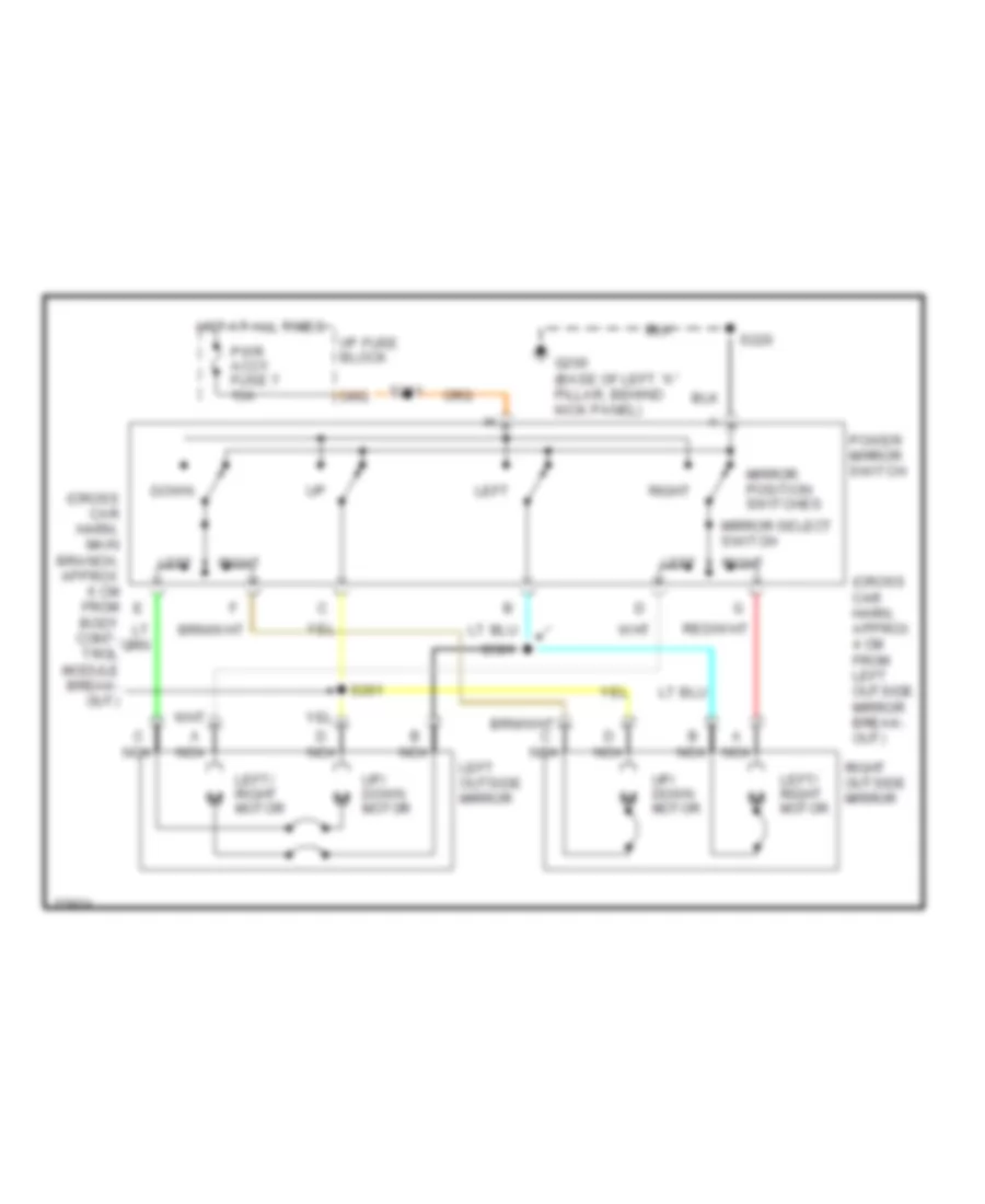
Электросхема привода зеркал для Pontiac Firebird 1997
Электросхема привода зеркал для Pontiac Firebird 1997 - Список элементов:
- (cross car harn, approx 4 cm from left outside mirror break- out)
- (cross car harn, main branch, approx 6 cm from body cont- trol module break- out)
- A nca
- Down
- G200 (base of left "a" pillar, behind kick panel)
- Hot at all times
- I/p fuse block
- Left
- Left outside mirror
- Left/ right motor
- Mirror position switches
- Mirror select switch
- Nca
- Power mirror switch
- Pwr accy fuse 7 15a
- Right
- Right outside mirror
- S211
- S220
- S261
- S501
- Up/ down motor
ПРИВОД ЛЮКА И КРЫШИ
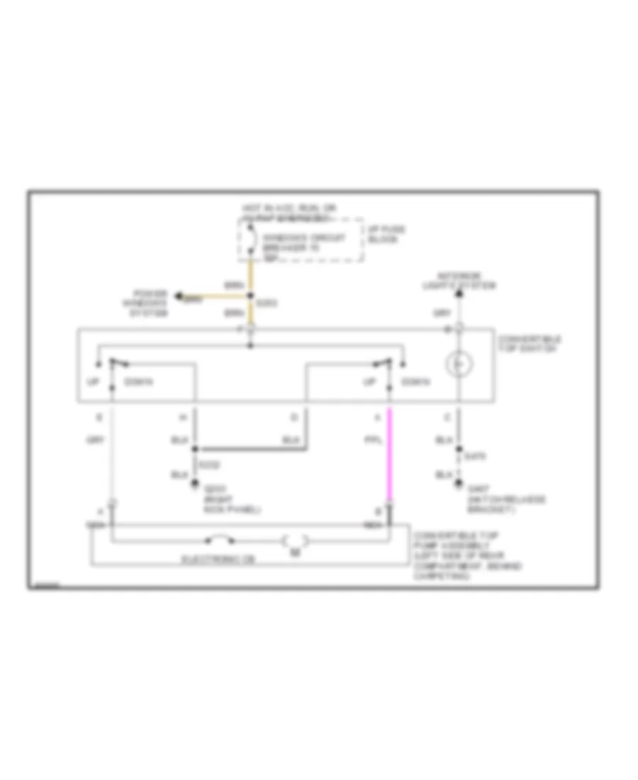
Электросхема складной крыши для Pontiac Firebird 1997
Электросхема складной крыши для Pontiac Firebird 1997 - Список элементов:
- Convertible top pump assembly (left side of rear compartment, behind carpeting)
- Convertible top switch
- Down
- Electronic cb
- G203 (right kick panel)
- G407 (hatch relaese bracket)
- Hot in acc, run, or w/ rap energized
- I/p fuse block
- Interior lights system
- Nca
- Power windows system
- S232
- S253
- S470
- Windows circuit breaker 15 30a
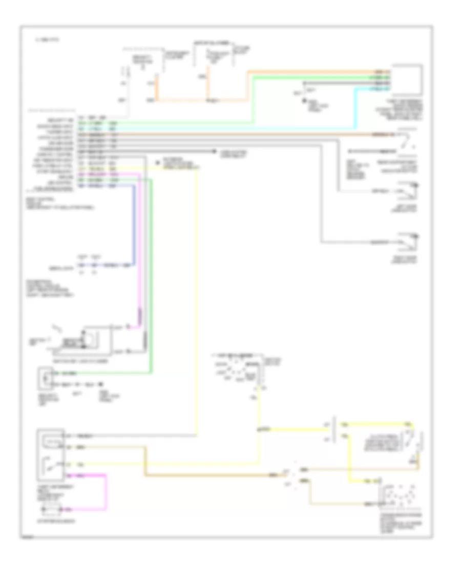
ПРИВОД СТЕКЛОПОДЪЕМНИКОВ
Электросхема стеклоподъемников для Pontiac Firebird 1997
Электросхема стеклоподъемников для Pontiac Firebird 1997 - Список элементов:
- (left kick panel)
- G200
- Hot in accy, run or with rap energized
- I/p fuse block
- Left power window switch
- Left window motor
- Left window switch
- Power window control module (center of dash mat, above floor tunnel)
- Right power window switch
- Right window motor
- Right window switch
- S208
- S220
- S263 (cross car harn, approx 15cm from breakout of 13-pin conn between left kick panel & steering column)
- Solid state (express down relay)
- Tan
- Windows circuit breaker 15 30a
Противоугонная система Сигнализация
Электросхема противоугонной сигнализации для Pontiac Firebird 1997
Электросхема противоугонной сигнализации для Pontiac Firebird 1997 - Список элементов:
- 1995 vftc c
- A/t
- A13
- Accy
- Body control module (above right i/p insulator panel)
- Bulb test
- C11
- Clutch pedal
- Compt, above battery)
- D11
- D12
- D13
- D14
- Driver door
- Exterior lights system (park lamp relay)
- Fuel enable signal
- G200 (left kick panel)
- G407 (bolted to hatch release bracket)
- Ground
- Hatch ajar input
- Horn rly control
- Horn system (horn relay)
- Hot at all times
- I/p fuse block
- Ignition key
- Ignition key lock cylinder
- Ignition switch
- Instrument cluster
- Key resistor input
- Led control
- Left door jamb switch
- Lock
- M/t
- Off
- Park lp relay ctrl
- Passenger door
- Position switch (mounted to top of clutch pedal)
- Powertrain control module (left rear of engine
- Pwr accy fuse 7 15a
- Rear compartment lid ajar indicator switch
- Resistor pellet
- Right door jamb switch
- Run
- S211
- S217
- S223
- Security ind
- Security indicator
- Security indicator led
- Serial data
- Shock sens input
- Start
- Start enable rly
- Starter solenoid
- Tamper input
- Theft deterrent relay (lower right side of i/p)
- Theft deterrent shock sensor (in right rear quarter panel, back of right rear wheelwell)
- Transmission range switch (in console, at base of shift control lever)
- Vin k
- Vin p
СИСТЕМА АНТИБЛОКИРОВОЧНОЙ ТОРМОЗНОЙ СИСТЕМЫ ABS
Электросхема антиблокировочной тормозной системы АБС (ABS), С Регулирование тягового усилия (1 из 2) для Pontiac Firebird 1997
Электросхема антиблокировочной тормозной системы АБС (ABS), С Регулирование тягового усилия (1 из 2) для Pontiac Firebird 1997 - Список элементов:
- (fwd lamp harn, in ebtcm breakout)
- (fwd lamp harn, in underhood electrical center breakout)
- (fwd lamp harness, near ebtcm breakout)
- (i/p harn, 24 cm from headlamp switch)
- (left side of i/p) electronic brake/traction control module (ebtcm)
- A10
- A11
- A12
- A13
- A14
- A15
- A16
- Abs enable relay ctrl
- Abs inop ind
- Abs relay
- Abs valve fuse 5 20a
- Abs warning in
- Adjuster assembly
- Asr ind (chevrolet)
- B10
- B11
- B12
- B13
- B14
- B15
- B16
- B17
- Battery power
- Brake ind
- Brake ind control
- Brake input
- Brake switch assembly (on brake pedal bracket)
- Cruise control system
- Data link connector (right of steering column)
- G101 (top of right shock tower)
- Gages fuse 9 10a
- Ground
- Hot at all times
- Hot in run
- Hot in run, bulb test or start
- I/p fuse block
- Ign
- Instrument cluster
- Instrument cluster system (brake warning)
- Left front motor control
- Left front return
- Left front signal
- Left front sol
- Left rear motor control
- Left rear return
- Left rear speed sens +
- Low trac ind
- Low trac ind ctrl
- Pnk
- Powertrain control module (pcm) (rear of right shock tower)
- Rear abs motor
- Red
- Right front motor control
- Right front return
- Right front sol
- Right front speed sens +
- Right rear motor control
- Right rear return
- Right rear speed sens +
- S111
- S175
- S180
- S206
- S228
- S270
- S271 (fwd lamp harn, near ebtcm breakout)
- S272 red
- S273
- Serial data link
- Solid state
- Spark retard
- Spark retard request
- Stop/haz fuse 1 20a
- Switched battery
- Tan
- Tcs active
- Tcs enable sw signal
- Tcs motor return
- Tcs off ind (pontiac)
- Tcs off/asr ind control
- Tp sens signal
- Tps sig
- Traction control active
- Traction control motor pack (below hydraulic modulator assembly)
- Underhood electrical center
Электросхема антиблокировочной тормозной системы АБС (ABS), С Регулирование тягового усилия (2 из 2) для Pontiac Firebird 1997
Электросхема антиблокировочной тормозной системы АБС (ABS), С Регулирование тягового усилия (2 из 2) для Pontiac Firebird 1997 - Список элементов:
- A c4
- A red
- Abs motor pack
- B c2
- B c3
- Brake valve combo
- F c1
- G120 (right side of engine)
- Hot in run
- Hydraulic modulator assembly (left front of engine compt)
- I/p fuse block
- Interior lights system
- Left front abs brake pressure valve solenoid
- Left front motor
- Left front wheel speed sensor
- Left rear wheel speed sensor
- Pnk
- Rear motor
- Red
- Right front abs brake pressure valve solenoid
- Right front motor
- Right front wheel speed sensor
- Right rear wheel speed sensor
- S207
- S215
- Tan
- Traction control switch
- Traction switch
- Turn b-u fuse 2 15a
Электросхема антиблокировочной тормозной системы АБС (ABS), без Регулирование тягового усилия для Pontiac Firebird 1997
Электросхема антиблокировочной тормозной системы АБС (ABS), без Регулирование тягового усилия для Pontiac Firebird 1997 - Список элементов:
- (fwd lamp harn, 16 cm from main branch)
- (fwd lamp harn, near ebcm breakout)
- (fwd lamp harness, in ebcm breakout)
- (top of right shock tower)
- A10
- A11
- A12
- A16
- Abs asr/tcs relay
- Abs bat fuse 6 5a
- Abs ignition fuse 1 5a
- Abs ind ctrl
- Abs inop indicator
- Abs motor pack
- Abs valve fuse 5 20a
- B12
- B17
- Batt
- Brake combo valve
- Brake in
- Brake ind ctrl
- Brake indicator
- Brake switch assembly (brake pedal bracket) c1
- Data link connector (right of steering column)
- Electronic brake control module (ebcm) (left side of i/p)
- Enable rly output
- G101
- Gages fuse 9 10a
- Ground
- Hot at all times
- Hot in run
- Hot in run, bulb test or start
- Hydraulic modulator assembly (left front of engine compt)
- I/p fuse block
- Ign
- Instrument cluster
- L fnt mtr-hi
- L fnt mtr-lo
- Left fnt spd sens +
- Left fnt spd sens -
- Left front abs brake pressure valve solenoid
- Left front motor
- Left front solenoid
- Left front wheel speed sensor
- Low trac ind ctrl
- Low traction indicator
- Pnk
- Rear motor
- Rear mtr-hi
- Rear mtr-lo
- Rear spd sens +
- Rear spd sens -
- Rear wheel speed sensor
- Red
- Right front abs brake pressure valve solenoid
- Right front motor
- Right front wheel speed sensor
- Rly coil ctrl
- Rt fnt mtr-hi
- Rt fnt mtr-lo
- Rt fnt solenoid
- Rt fnt spd sens +
- Rt fnt spd sens -
- S111
- S175
- S180
- S206
- S243
- S270
- S272
- S273
- Serial data
- Solid state
- Stop/hazard fuse 1 20a
- Tan
- Underhood electrical center
СИСТЕМА КОНДИЦИОНЕРА
Электросхема кондиционера A/C для Pontiac Firebird 1997
Электросхема кондиционера A/C для Pontiac Firebird 1997 - Список элементов:
- (3.8l)
- (3.8l: eng harn, 11 cm from injector 4 breakout) (5.7l: eng harn, 28 cm back from a/c clutch breakout)
- (3.8l: eng harn, 33 cm back from a/c compressor clutch conn)
- (3.8l: eng harn, 6cm from injector 1 breakout) (5.7l: eng harn, 4cm from trans- mission breakout)
- (3.8l: eng harn, 7.5 cm from inj 4 breakout) (5.7l: eng harn, 33 cm back from a/c comp clutch breakout)
- (5.7l on water pump)
- (5.7l: eng harn, 8 cm from injector 4 breakout)
- (chevy: i/p harn, 5 cm from defog sw breakout) s216 (pont: i/p harn, 5 cm from i/p cluster breakout)
- (eng harn, 14cm from trans- mission breakout)
- (eng harn, 8cm from pcm breakout)
- (forward lamp harn, 4 cm from cooling fan breakout)
- (forward lamp harn, in electrical center breakout)
- (in evaporator core)
- (in underhood electrical center)
- (near top left of the radiator, on the t-bar)
- +5v
- 0.31 ohm total
- 0.61 ohm
- 1.85 ohm
- 3.8l
- 5.7l
- A/c clutch diode (1 amp)
- A/c compressor clutch
- A/c compressor relay (in underhood electrical center)
- A/c evaporator temperature sensor (5.7l)
- A/c refrigerant pressure sensor (above right shock tower)
- A/c request
- A/c-cruise fuse 12 15a
- A/p fan fuse 7 25a
- Bi-lv
- Blend
- Blower motor
- Blower resistors (in hvac module)
- Blower switch
- C 1995 vftc
- C tan
- Center
- Clutch status
- Compressor ctrl
- Def
- Ect sensor input
- Engine coolant temperature sensor (3.8l: under throttle body)
- Engine cooling fan relay 1
- Engine cooling fan relay 2 (in underhood electrical center)
- Engine cooling fan relay 3 (in underhood electrical center)
- Fan rly 1 control
- Fan rly 2 & 3 control
- G108
- G112 (left side of engine)
- G200 (left kick panel)
- G203 (right kick panel)
- High blower relay (under i/p, above left side of floor tunnel)
- Hot at all times
- Hot in run
- Hot in run, bulb test or start
- Htr
- Htr/ def
- Htr/def
- Hvac control (blower switch contacts are make before break contacts)
- Hvac fuse 6 20a
- I/p fuse block
- Interior lights system
- Left engine cooling fan
- Max
- Nca
- Norm
- Off
- Pnk
- Power distribution system
- Powertrain control module (in engine compt, rear of right shock tower)
- Probe (inserted in evaporator)
- Red
- Right engine cooling fan
- S105 (eng harn, 4 cm from pcm breakout)
- S114
- S115
- S117
- S119
- S122
- S165 (forward lamp harn, 7cm from pnk underhood electrical center breakout)
- S166
- S177
- S248 (chevy: i/p harn, 4 cm from blower motor relay breakout) (pont: i/p harn, 2 cm from radio connectors breakout)
- Selector switch
- Sensor ground
- Sensor input
- Solid state
- Tan
- Underhood electrical
- Underhood electrical center
- Vent
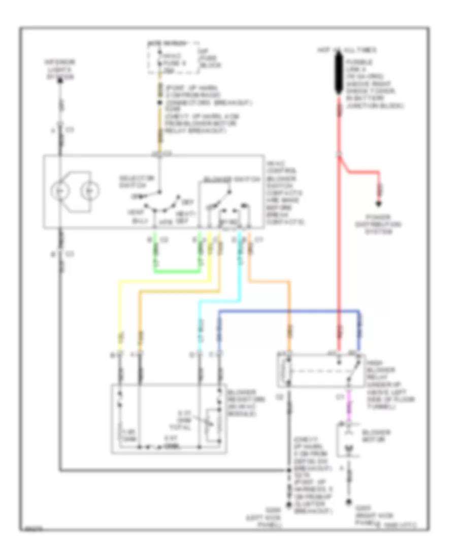
схема нагревателя для Pontiac Firebird 1997
схема нагревателя для Pontiac Firebird 1997 - Список элементов:
- (chevy: i/p harn, 5 cm from defog sw breakout) s216 (pont: i/p harness, 5 cm from i/p cluster breakout)
- 0.31 ohm total
- 0.61 ohm
- 1.85 ohm
- Bi-lv
- Blower motor
- Blower resistors (in hvac module)
- Blower switch
- C 1995 vftc
- C tan
- Def
- G200 (left kick panel)
- G203 (right kick panel)
- Heat/ def
- High blower relay (under i/p, above left side of floor tunnel)
- Hot at all times
- Hot in run
- Htr
- Hvac control (blower switch contacts are make before break contacts)
- Hvac fuse 6 20a
- I/p fuse block
- Interior lights system
- Nca
- Off
- Power distribution system
- Red
- Selector switch
- Tan
- Vent
СИСТЕМА КРУИЗКОНТРОЛЯ
Электросхема системы круизконтроля для Pontiac Firebird 1997
Электросхема системы круизконтроля для Pontiac Firebird 1997 - Список элементов:
- "low trac" ind
- (v6 vin k)
- (v8 vin p)
- 4000 pulses/mile
- A c1
- A/c-cruise fuse 12 15a
- A/t
- A16
- Abs/tcs active
- B c1
- B12
- Brake input
- Brake switch assembly (on brake pedal bracket)
- Clutch anticipate/ cruise release
- Cruise control module (left front side of engine compt)
- Cruise engaged
- Cruise inhibit
- Cruise release brake switch (v8 vin p) (mounted on brake pedal bracket)
- Cruise release/ brake switch (on brake pedal bracket)
- Cruise status
- Cruise switch
- Electronic brake/ traction control module (ebtcm) (under i/p, next to left hinge pillar)
- G100 (bolted to left front frame rail)
- Gages fuse 9 10a
- Ground
- Hot at all times
- Hot in run, bulb test or start
- I/p fuse block
- Ignition input
- Instrument cluster
- M/t
- Multi-function lever
- Nca
- Off
- On/off input
- Pnk
- Powertrain control module (pcm) (rear of engine compt, behind right shock tower)
- R/a
- Resume/accel input
- S165
- S206
- S242 (i/p harness, left side of i/p)
- S271 (fwd lamp harness, 4 cm from ebtcm)
- S278 (fwd lamp harness, left side of i/p)
- Set/ coast sw
- Set/coast input
- Stop/hazard fuse 6 20a
- Switch (v6 vin k) (mounted on clutch pedal bracket)
- Underhood electrical center
- V6 vin k only
- Vehicle speed sensor (rear left side of transmission)
- Vss inpt hi
- Vss input
- Vss input lo
- W/ traction control
- W/o traction control
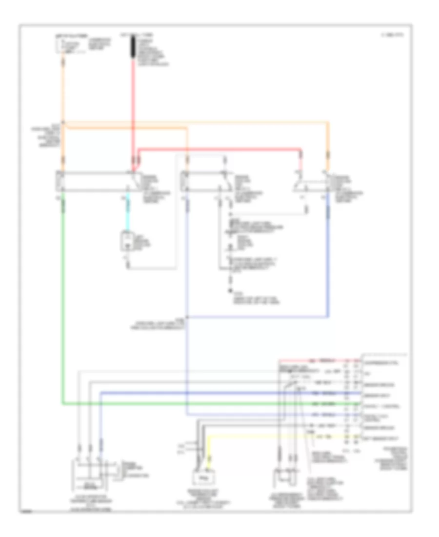
СИСТЕМА ОХЛАЖДЕНИЯ
Электросхема системы охлаждения для Pontiac Firebird 1997
Электросхема системы охлаждения для Pontiac Firebird 1997 - Список элементов:
- (3.8l)
- (3.8l: eng harn, 6cm from injector 1 breakout) (5.7l: eng harn, 4cm from trans- mission breakout)
- (5.7l on water pump)
- (eng harn, 14cm from trans- mission breakout)
- (eng harn, 8cm from pcm breakout)
- (in evaporator core)
- (in underhood electrical center)
- (near top left of the
- +5v
- 3.8l
- 5.7l
- A/c evaporator temperature sensor (5.7l)
- A/c refrigerant pressure sensor (above right shock tower)
- A/p fan fuse 7 25a
- C 1995 vftc
- Compressor ctrl
- Ect sensor input
- Engine coolant temperature sensor (3.8l: under throttle body)
- Engine cooling fan relay 1
- Engine cooling fan relay 2 (in underhood electrical center)
- Engine cooling fan relay 3 (in underhood electrical center)
- Fan rly 1 control
- Fan rly 2 & 3 control
- G108
- Hot at all times
- Left engine cooling fan
- Powertrain control module (in engine compt, rear of right shock tower)
- Probe (inserted in evaporator)
- Radiator, on the t-bar)
- Red
- Right engine cooling fan
- S117
- S119
- S122
- S166 (forward lamp harn, 4 cm from cooling fan breakout)
- S177 (forward lamp harn, in electrical center breakout)
- Sensor ground
- Sensor input
- Solid state
- Underhood electrical center
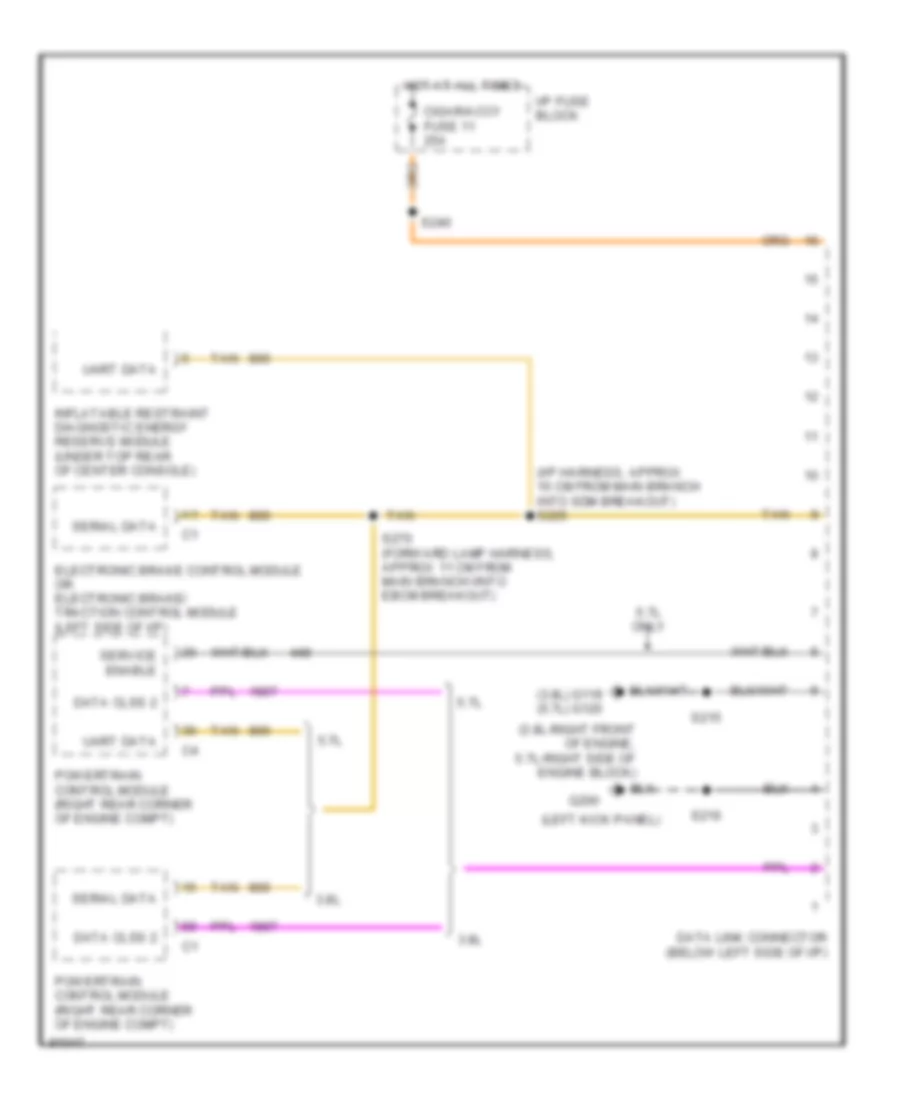
СИСТЕМА ПЕРЕДАЧИ ДАННЫХ
Электросхема компьютерной линии передачи данных CAN для Pontiac Firebird 1997
Электросхема компьютерной линии передачи данных CAN для Pontiac Firebird 1997 - Список элементов:
- (3.8l) g119 (5.7l) g120
- (3.8l-right front of engine, 5.7l-right side of engine block)
- (i/p harness, approx 10 cm from main branch into sdm breakout) s225
- (left kick panel)
- 3.8l
- 5.7l
- 5.7l only
- Cigar/accy fuse 11 25a
- Data clss 2
- Data link connector (below left side of i/p)
- Electronic brake control module or electronic brake/ traction control module (left side of i/p)
- G200
- Hot at all times
- I/p fuse block
- Inflatable restraint diagnostic energy reserve module (under top rear of center console)
- Powertrain control module (right rear corner of engine compt)
- S215
- S216
- S240
- S270 (forward lamp harness, approx 11 cm from main branch iinto ebcm breakout)
- Serial data
- Service enable
- Tan
- Uart data
СИСТЕМА УПРАВЛЕНИЯ ДВИГАТЕЛЯ
3.8L
3.8L (VIN K), Электросхема системы управления двигателя (1 из 3) для Pontiac Firebird 1997
3.8L (VIN K), Электросхема системы управления двигателя (1 из 3) для Pontiac Firebird 1997 - Список элементов:
- (i/p harn, 10 cm from main branch, in inflatable restraint sdm breakout)
- (i/p harn, left side of i/p)
- 18x crank pos in
- 3x fuel ctrl ref hi
- 5v ref out
- 87a
- A/c comp ctrl
- A/c request in
- Actuators fuse 2 15a
- Air conditioning system
- Anti-theft system
- Brake/tcc sw in
- Cam pos in
- Clutch anticipate
- Cooling fans system
- Cruise control system
- Cruise engaged sig
- Data link connector (left i/p)
- Dlc class 2 data
- Egr valve sol ctrl
- Engine cool fan #1
- Engine cool fan #2
- Engine data sens grd
- Evap emissions canister vacuum switch (top right rear of engine)
- Evap purge diag sw
- Evap purge sol ctrl
- Evaporative emissions canister purge valve (right center of engine)
- Fuel pump prime connector (top rear of right shock tower)
- Fuel pump relay (left kick panel, under carpet)
- Fuel pump rly ctrl
- G125 (front of engine)
- Hot at all times
- Hot in run
- Hot in run, bulb test or start
- I/p fuse block
- Iac control
- Icm module bypass
- Idle air control (iac) valve (on side of throttle assembly)
- Ignition ctrl in
- Ignition ctrl ref lo
- Instrument cluster system
- Intake air temperature (iat) sensor (air duct, front of intake manifold)
- Maf sensor in
- Mass air flow sensor (front of throttle body)
- Mil lamp control
- Pass-key fuel enable
- Pcm bat fuse 3 15a
- Pcm ground
- Pcm ign fuse 13 10a
- Pnk
- Power (battery)
- Power (ignition)
- Powertrain control module (right side of engine compt)
- Red
- S110
- S127
- S132
- S215
- S225
- S242
- Second gear start
- Tan
- Tcc enable sol ctrl
- Tcc solenoid ctrl
- Uart data link
- Underhood electrical center
- Vehicle speed sensor (left rear of transmission)
- Vss in
- Vss out-4000 ppm
- Vss return
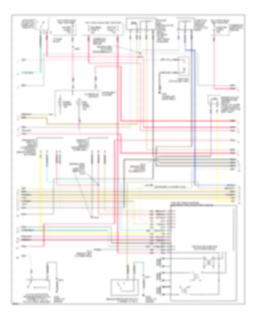
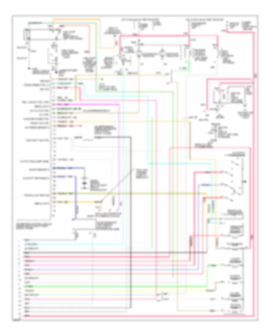
3.8L (VIN K), Электросхема системы управления двигателя (2 из 3) для Pontiac Firebird 1997
3.8L (VIN K), Электросхема системы управления двигателя (2 из 3) для Pontiac Firebird 1997 - Список элементов:
- (engine harn, 16 cm from trans breakout)
- (engine harn, near injector 3 breakout) s145
- (top left side of engine) electronic ignition control module
- 2nd gear start ind
- A14
- Alternator ind input
- Camshaft position sensor (engine front cover assy)
- Check engine ind
- Clutch anticipate/ cruise release switch (5 speed m/t only) (clutch pedal bracket)
- Crankshaft position sensor (lower front of engine, behind harmonic b balancer)
- Eng sens fuse 10 20a
- Engine coolant temperature sensor (front of lower intake manifold, under throttle body assy)
- Exhaust gas recirculation vaccum control signal solenoid valve (left front of engine)
- Fuel pump (top of fuel tank)
- G114 (rear of left cylinder head)
- G125 (front of engine)
- G300 (under left front seat)
- Gauges fuse 9 10a
- Hot in run, bulb test or start
- I/p fuse block
- Ignition amplifier and switching module
- Ignition fuse 11 10a
- Injector fuse 9 15a
- Instrument cluster
- Instrument cluster (tach)
- Nca
- Plugs spark
- Pnk
- Red
- S117
- S119 (engine harn, 6 cm from pcm breakout)
- S144
- S206
- S215
- Second gear start switch (4 speed a/t only)
- Spark plugs
- Stoplamp/ tcc switch (under left side of i/p)
- Tan
- Throttle position sensor (throttle body)
- Underhood electrical center
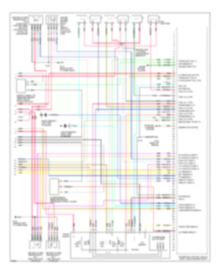
3.8L (VIN K), Электросхема системы управления двигателя (3 из 3) для Pontiac Firebird 1997
3.8L (VIN K), Электросхема системы управления двигателя (3 из 3) для Pontiac Firebird 1997 - Список элементов:
- (engine harn, 11 cm from transmission breakout)
- 1-2 ctrl sol
- 2-3 ctrl sol
- 3-2 ctrl sol
- 3-2 downshift sol ctrl
- A/c press sens in
- A/c refrigerant pressure sensor (above right shock tower)
- Alternator ind ctrl
- Cruise control system
- Cruise inhibit out
- Ect sensor in
- Fuel inj 1 ctrl
- Fuel inj 2 ctrl
- Fuel inj 3 ctrl
- Fuel inj 4 ctrl
- Fuel inj 5 ctrl
- Fuel inj 6 ctrl
- Fuel injectors
- G114 (rear of left cylinder head)
- G125 (front of engine)
- Generator control
- Heated oxygen sensor bank 1 no 1 (left exhaust manifold)
- Heated oxygen sensor bank 1 no 2 (in exhaust pipe, between exhaust manifolds and catalytic converter)
- Heated oxygen sensor bank 1 no 3 (behind catalyst, in exhaust pipe)
- Heated oxygen sensor bank 2 no 1 (right exhaust manifold)
- Iat sensor in
- Knock sens #1 in
- Knock sens #2 in
- Knock sensor 1 (left side of engine)
- Knock sensor 2 (right side of engine)
- Lft manifold ho2s hi
- Lft manifold ho2s lo
- Linear egr pos sens in
- Manifold absolute pressure sensor (right side of intake manifold)
- Map sensor in
- Nca
- Pcm ground
- Pcs hi
- Pcs low
- Pcs sol
- Pnk
- Post-cat ho2s hi
- Post-cat ho2s lo
- Powertrain control module (right side of engine compt)
- Pre-cat h02s hi
- Pre-cat ho2s lo
- Range sens 'a' in
- Range sens 'b' in
- Range sens 'c' in
- Red
- Rnge 'a'
- Rnge 'b'
- Rnge 'c'
- Rt manifold ho2s hi
- Rt manifold ho2s lo
- S101
- S104
- S108
- S110
- Second geat start in
- Starting/ charging system
- Tan
- Tcc pwm sol
- Tcc sol
- Tft sensor
- Tp sensor in
- Tr pressure switch assy
- Trans shift sol 'a'
- Trans shift sol 'b'
- Trans temp sens in
- Trans- mission
5.7L
5.7L (VIN P), Электросхема системы управления двигателя (1 из 3) для Pontiac Firebird 1997
5.7L (VIN P), Электросхема системы управления двигателя (1 из 3) для Pontiac Firebird 1997 - Список элементов:
- (3-2 a/t)(skip m/t) shift
- (front of left cylinder head)
- (rearward of right front shock tower)
- (right side of engine block)
- (right side of engine block) g120
- 5 volt ref
- A/c clutch status
- A/c request sig
- A/c system
- Air pump relay ctrl
- B from ignition coil (diagram 3 of 3)
- Battery
- Body control module (right side of i/p)
- Can purge
- Coil wire
- Coolant fan relays
- Crankshaft position sensor (lower front cover of engine)
- Cruise control, speedometer & radio
- Dist ignition feed
- Dist ref low sig
- Distributor (frt center of engine)
- Ebtcm tp sensor sig
- Egr solenoid ctrl
- Electronic brake/traction control module (left side of i/p)
- Evap canister purge vacuum switch (right top of intake manifold)
- Fuel enable sig
- Fuel injector #1
- Fuel injector #2
- Fuel injector #3
- Fuel injector #4
- Fuel injector #5
- Fuel injector #6
- Fuel injector #7
- Fuel injector #8
- Fuel pump relay ctrl
- G110
- G120
- Ground
- Hi res signal
- High resolution sig
- Hot at all times
- Hot in run, bulb test or start
- I/p fuse block
- Ign voltage
- Ignition
- Ignition ctrl
- Inj # 8 ctrl
- Inj #1 ctrl
- Inj #2 ctrl
- Inj #3 ctrl
- Inj #4 ctrl
- Inj #5 ctrl
- Inj #6 ctrl
- Inj #7 ctrl
- Injector fuse 9 15a
- Instrument cluster
- Low res signal
- Low resolution sig
- Maf sensor in
- Mass air flow sensor (on air duct in front of intake manifold)
- Optical sensor
- Pcm bat fuse 3 15a
- Pcm ign fuse 13 10a
- Pnk
- Powertrain control module
- Pri lo spd rly ctrl
- Red
- Ref 3x
- Ref low
- S101
- S102
- S103 (engine harn, 10 cm from trans- mission breakout)
- S106
- S110
- S132
- Sec hi spd rly ctrl
- Sensor ground
- Solid state
- Spark plugs
- Tach out
- Tcs spark retard req
- To fuel pump relay (diagram 3 of 3)
- Trans 1-2 shift ctrl
- Trans 2-3 shift ctrl
- Under- hood electrical center
- Vehicle speed sensor (left rear of transmission)
- Vss ground
- Vss out
- Vss signal
5.7L (VIN P), Электросхема системы управления двигателя (2 из 3) для Pontiac Firebird 1997
5.7L (VIN P), Электросхема системы управления двигателя (2 из 3) для Pontiac Firebird 1997 - Список элементов:
- (engine harness, 18 cm from transmission breakout)
- (fwd lamp harn, in secondary air injection pump breakout) s189
- (i/p harn, 16 cm from theft de- terrent relay)
- (in engine harness, 15 cm from pcm breakout)
- (on base of shift control lever)
- (rearward of right front shock tower) powertrain control module
- (right side of engine block)
- 25a
- A tan
- A/p fan
- Actuators fuse 2 15a
- Bank 1 h02 sensor lo
- Bank 1 ho2 sensor hi
- Bank 1 ho2 sensor lo
- Bank 1 left front heated oxygen sensor 1 (left side of manifold)
- Bank 2 ho2 sensor hi
- Bank 2 ho2 sensor lo
- Bank 2 right front heated oxygen sensor 1 (right side of manifold)
- Bank 2 right rear heated oxygen sensor 2 (left side of converter)
- Brake switch signal
- Canister purge solenoid valve (right center of engine, on manifold)
- D pnk
- Ect sensor in
- Egr vacuum control signal solenoid valve (left rear of engine, on intake plenum)
- Electronic brake/traction control module (left side of i/p)
- Eng sensor fuse 10 20a
- Engine coolant temperature sensor (front of engine, in water pump)
- Evaporatine emission
- Fuse 7
- G108 (top left side of radiator)
- G110 (left front of engine)
- G120
- G120 (right side of engine block)
- Ground
- Ho2s bank 2 sensor 2 (right side of converter)
- Hot at all times
- Hot in run
- Hot in run, bulb test or start
- Iac coil a hi
- Iac coil a lo
- Iac coil b hi
- Iac coil b lo
- Iat sensor in
- Idle air control valve (right front of throttle body)
- Intake air temperature sensor (on air duct, in front of intake manifold)
- Manifold absolute a
- Map sensor in
- Nca
- Pnk
- Pnp sig
- Pressure sensor (right side of intake manifold)
- Red
- Red a
- Red b
- S104
- S108
- S110
- S117
- S119
- S122 (engine harness, 14 cm from transmission breakout)
- S127
- S177
- S215
- S234
- Second- ary air pump relay
- Secondary air injection bleed solenoid valve (front left of engine)
- Secondary air injection pump assembly (front left frame rail)
- Tan
- Tcs active
- Throttle position sensor (right front intake)
- Tp sensor in
- Trans press ctrl hi
- Trans range sig a
- Trans range sig b
- Trans range sig c
- Transmission position switch
- Under- hood electrical center
5.7L (VIN P), Электросхема системы управления двигателя (3 из 3) для Pontiac Firebird 1997
5.7L (VIN P), Электросхема системы управления двигателя (3 из 3) для Pontiac Firebird 1997 - Список элементов:
- (front of left cylinder head)
- (fwd lamp harness, in ebtcm breakout)
- (left rear of trans)
- (right of steering column)
- (right side of engine block)
- (under drivers seat) g300
- 1-2 shift solenoid
- 2-3 shift solenoid
- 3-2 ctrl solenoid
- A/c clutch ctrl
- A/c compressor relay
- A/c evap temp sens in
- A/c evaporator temp sensor (mounted in evaporator core)
- A/c press sensor in
- A/c refrigerant pressure sensor (above right shock tower)
- A/t
- Automatic transmission
- Brake switch (brake pedal support)
- Canister purge ctrl
- Cluster
- Coil driver
- Data link connector
- Eng sensor fuse 10 20a
- From i/p fuse block (diagram 1 of 3)
- Fuel pump prime connector (top rear of right shock tower)
- Fuel pump relay (forward of left kick panel)
- Fuel pump/ level sender (in fuel tank)
- Fuse block
- G110
- G110 (front of left cylinder head)
- G120
- Gages fuse 9 10a
- Ground
- Hei coil wire
- Hot in run, bulb test or start
- Ign
- Ign ctrl
- Ignition
- Ignition coil (front left side of engine)
- Ignition coil module (front left side of engine)
- Ignition fuse 11 10a
- Instru-
- Knock sensor (bottom right side of engine block)
- Knock sensor in
- M/t
- Malfunction indicator
- Ment
- Mil ctrl
- Output/field serv enbl
- Pnk
- Pnk c2
- Powertrain control module (rearward of right front shock tower)
- Pressure control solenoid
- Red
- Rev lockout sol ctrl
- Reverse lockout solenoid
- S104
- S107
- S108
- S206
- S215
- S270
- Serial data
- Skip shift ind ctrl
- Skip shift indicator
- Skip shift solenoid (left middle of trans)
- Tan
- Tcc pwm solenoid
- Tcc solenoid
- Tcc switch
- To distributor (diagram 1 of 3)
- Trans fluid temp sensor
- Trans fluid temp sig
- Trans press ctrl lo
- Trans tcc ctrl
- Under- hood electrical center
Система Фар
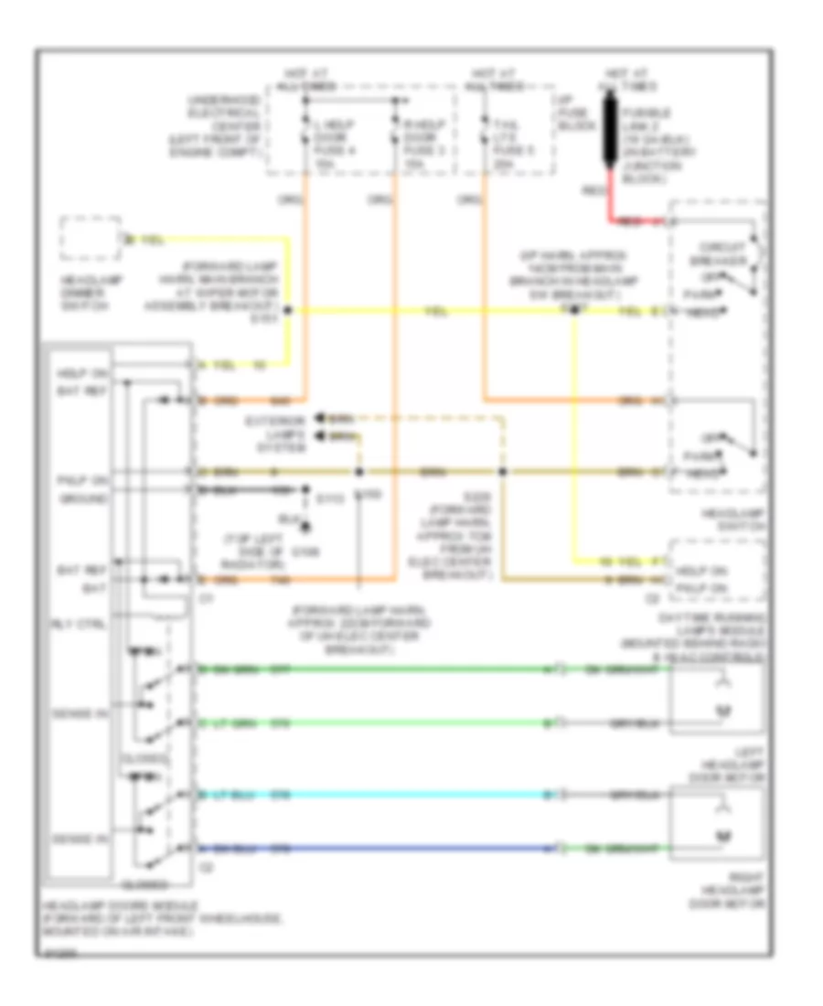
дверная схема фары для Pontiac Firebird 1997
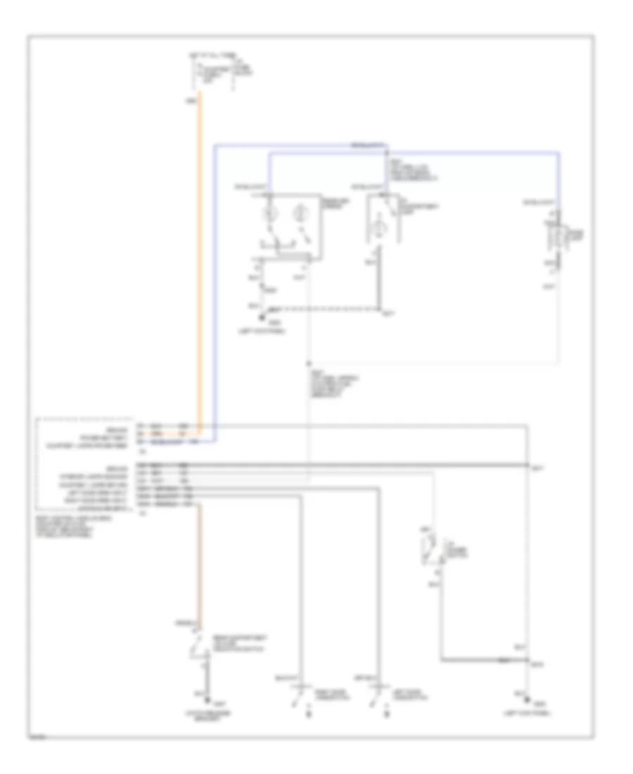
дверная схема фары для Pontiac Firebird 1997 - Список элементов:
- (forward lamp harn, approx 22cm forward of uh elec center breakout)
- (forward lamp harn, main branch at wiper motor assembly breakout) s151
- (i/p harn, approx 14cm from main branch in headlamp sw breakout) s227
- (top left side of radiator)
- Bat
- Bat ref
- Circuit breaker
- Closed
- Daytime running lamps module (mounted behind radio & hvac controls)
- Exterior lamps system
- G108
- Ground
- Hdlp on
- Head
- Headlamp dimmer switch
- Headlamp doors module (forward of left front wheelhouse, mounted on air intake)
- Headlamp switch
- Hot at all times
- I/p fuse block
- L hdlp door fuse 4 15a
- Left headlamp door motor
- Off
- Open
- Park
- Pklp on
- R hdlp door fuse 3 15a
- Red
- Right headlamp door motor
- Rly ctrl
- S113
- S150
- S226 (forward lamp harn, approx 7cm from uh elec center breakout)
- Sense in
- Tail lts fuse 5 20a
- Underhood electrical center (left front of engine compt)
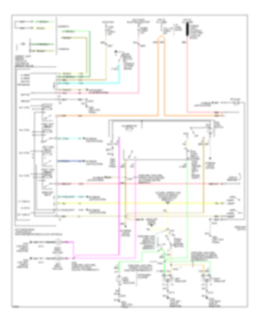
Электросхема фар и противотуманных фар для Pontiac Firebird 1997
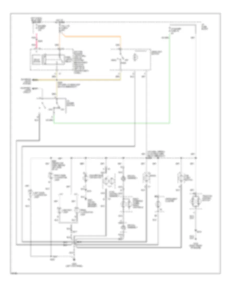
Электросхема фар и противотуманных фар для Pontiac Firebird 1997 - Список элементов:
- (forward lamp harn, approx 22cm forward of uh elec center breakout)
- (forward lamp harn, approx 7cm from uh elec center breakout)
- (forward lamp harn, main branch at brake pressure differential sw breakout)
- (forward lamp harn, main branch at wiper motor assembly breakout)
- (i/p harn, approx 14cm from main branch in headlamp sw breakout) s227
- A11
- Al sens
- Ambient light sensor (top of i/p, mounted on defrost grille)
- Canadian
- Circuit breaker
- Daytime running lamps module (mounted behind radio & hvac controls)
- Domestic
- Exterior lights system
- Fog lamp relay (under- hood elec center) (left front of engine compt.)
- Fog lamp switch
- G108 (top left side of radiator)
- G109 (top right side of radiator)
- G200 (left kick panel)
- Gages fuse 9 10a
- Ground
- Head
- Head- lamp dimmer switch
- Headlamp doors circuit
- Headlamp switch
- Headlight relay
- High beam indicator
- Hl on in
- Hot at all times
- Hot in run
- Hot in run, bulb test or start
- I/p fuse block
- Ignition
- Instrument cluster
- Instrument cluster system
- Interior lights system
- Left front fog lamp
- Left headlamp
- Left turn relay
- Lt turn in
- Nca
- Off
- On indicator
- Park
- Park brake switch (in console, on park brake)
- Park light relay
- Pnk
- Prk brake
- Red
- Right front fog lamp
- Right headlamp
- Right turn relay
- Rly ctrl
- Rt turn in
- S112
- S113
- S150
- S151
- S152
- S153
- S160 (forward lamp harn, approx 4cm from coolant fan breakout)
- S206
- S207
- S216
- Sw illum
- Tail lts fuse 5 20a
- Tan
- Turn b-u fuse 2 15a
СИСТЕМЫ СИДЕНИЙ
Электросхема привода сидений с 6 путями для Pontiac Firebird 1997
Электросхема привода сидений с 6 путями для Pontiac Firebird 1997 - Список элементов:
- (under driver's seat)
- Back
- Defog/seats circuit breaker 12 30a
- Down
- Driver seat assembly
- E tan a
- Entire seat
- For- ward
- Forward/ back motor
- Front height
- Front height motor
- G300
- Hot at all times
- I/p fuse block
- Nca
- Power seat actuator assembly
- Power seat switch
- Rear height
- Rear height motor
- S252
Электросхема регулировки поясницы для Pontiac Firebird 1997
Электросхема регулировки поясницы для Pontiac Firebird 1997 - Список элементов:
- (driver seat harn, in breakout to control module) s355
- (driver seat harn, near breakout to ctrl module) s345
- (pass seat harn, near breakout to pwr seat switch) s360
- Air in/out
- Cutout relay
- Deflate
- Deflate relay
- Defog/seats circuit breaker 12 30a
- Driver power seat switch
- Driver seat assembly
- G300 (under driver's seat)
- Hot at all times
- I/p fuse block
- Inflate
- Inflate relay
- Lateral
- Lateral bladder
- Lumbar
- Lumbar bladder
- Passenger power seat switch
- Passenger seat assembly
- Power seat control module
- Pressure switch
- Pump assembly
- S200
- S335
- S340 (driver seat harn, in breakout to control module)
- S350 (driver seat harn, near breakout to control module)
- Solenoid valve assembly
Стартер Генератор
Электросхема Генератора для Pontiac Firebird 1997
Электросхема Генератора для Pontiac Firebird 1997 - Список элементов:
- "check gages" indicator
- (not used)
- (not used) f
- (not used) s
- (right front shock tower)
- (right side of engine block)
- A14
- Battery
- G103
- G120
- Gages fuse 9 10a
- Generator
- Generator control
- Generator lamp control
- Hot in run, bulb test or start
- I/p fuse block
- Instrument cluster
- Pnk
- Power distribution system
- Powertrain control module (behind right shock tower)
- Red
- S206
- Solid state
- Starting circuit
- Vin k
- Vin p
Электросхема стартера для Pontiac Firebird 1997
Электросхема стартера для Pontiac Firebird 1997 - Список элементов:
- (i/p harness, main branch, 4 cm from sdm breakout)
- (right front shock tower)
- (right side of engine block)
- A/t
- Accy
- Battery
- Battery junction block
- Body control module (above right i/p insulator panel)
- Bulb test
- C11
- Charging circuit
- Clutch start switch (clutch pedal bracket)
- G103
- G120
- Hold- in coil
- Ignition switch
- Lock
- M/t
- Off
- Power distribution system
- Pull- in coil
- Red
- Relay control
- Run
- S200 red
- S223
- Start
- Starter motor
- Starter solenoid
- Theft deterrent relay (right side of i/p)
- Transmission range switch (under console)
Стеклоочистители и Стеклоомыватели Дворники
Электросхема стеклоочистителя, дворников и омывателя для Pontiac Firebird 1997
Электросхема стеклоочистителя, дворников и омывателя для Pontiac Firebird 1997 - Список элементов:
- 24k
- C 1995 vftc
- End of sweep switch
- Fuse block
- G108 (near top left side of radiator, in top 0f t-bar)
- Hot in acc or run
- Low speed relay
- Mist
- Nca
- Nca e
- Nca h
- Off
- Park relay
- Park switch
- Pnk
- Pulse
- Red
- S113
- Washer pump motor (below engine hood latch)
- Washer switch
- Wiper isolation diode (in fwd lts hrn base of steeering column)
- Wiper motor assembly
- Wiper switch
- Wiper/ wash fuse 14 25a
- Wiper/ washer switch assembly
ЦЕНТРАЛЬНЫЙ ЗАМОК
Электросхема центрального замка для Pontiac Firebird 1997
Электросхема центрального замка для Pontiac Firebird 1997 - Список элементов:
- (cross-car harness, 39cm from power window control module breakout) s267
- (cross-car harness,11cm from left power mirror control switch harness breakout) s504
- (w/ remote keyless only)
- All doors lock
- Bat
- Body control module (bcm) (behind right side of i/p, behind kick panel)
- Courtesy fuse b 20a
- D11
- D12
- Driver dr jamb sw
- Driver dr unlock
- G200 (near base of left "a" pillar, bolted to i/p mounting stud behind kick panel)
- Ground
- Hot at all times
- I/p fuse block
- Int lamps feed
- Int lamps on
- Int lamps return
- Interior lights system
- Left door jamb switch
- Left door lock actuator
- Left power door lock switch
- Lock
- Lock input
- Pass dr jamb sw
- Pass dr unlock
- Right door jamb switch
- Right door lock actuator
- Right power door lock switch
- S217
- S220
- S268 (cross-car harn, 45cm from power window control module breakout)
- Tan
- Unlock
- Unlock input

 Čeština
 Dansk
Dansk Deutsch
 Ελληνικά
 English
 English
 Español
 Suomi
Suomi Français
 Français
 עברית
עברית Hrvatski
 Magyar
 Italiano
 日本語
日本語 한국어
한국어 Nederlands
 Polski
 Português
 Română
 Русский
 Slovenčina
 Slovenščina
 Svenska
 Türkçe
 中文 (中国)