POWER DISTRIBUTION
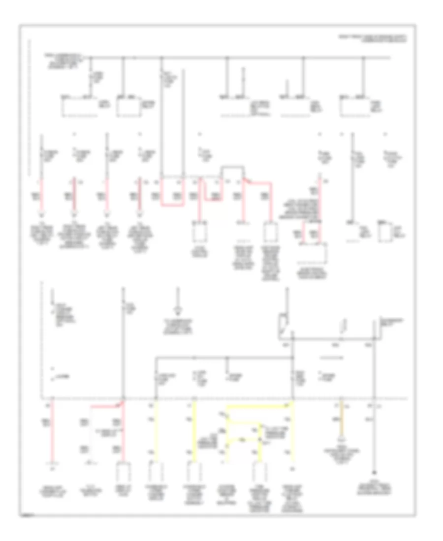
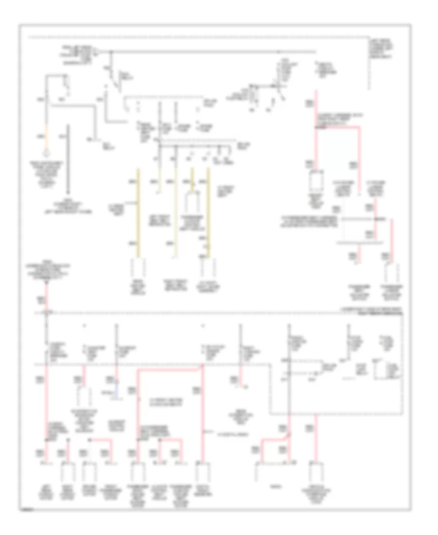
Power Distribution Wiring Diagram (1 of 7) for Cadillac STS V 2007
 https://portal-diagnostov.com/license.html
Automotive Electricians Portal FZCO
Automotive Electricians Portal FZCO
https://portal-diagnostov.com/license.html
https://portal-diagnostov.com/license.html
Automotive Electricians Portal FZCO
Automotive Electricians Portal FZCO
List of elements for Power Distribution Wiring Diagram (1 of 7) for Cadillac STS V 2007:
- (3.6l & 4.6l)
- (3.6l)
- (3.6l: in engine harness, 27 cm from evap canister purge solenoid valve connector) (4.6l: in engine harness, 15 cm from fuel injector 5 connector) s101
- (4.4l)
- (4.6l)
- (engine harness, 36 cm from tcm connector)
- (in engine poa harness, 18 cm from ignition coil 1 connector) s127
- (in ignition coil harness, 30 cm from ignition coil module 1 connector) s142
- (not used)
- (right front side of engine compt) underhood fuse block
- 3.6l
- 4.4l
- 4.6l
- 4.6l/ 4.4l
- Automatic headlamp dimming relay
- Battery
- Blower fuse 40a
- Blower relay
- C1 h
- Camshaft position (cmp) actuator solenoid exhaust bank 1
- Camshaft position (cmp) actuator solenoid exhaust bank 2
- Camshaft position (cmp) actuator solenoid intake bank 1
- Camshaft position (cmp) actuator solenoid intake bank 2
- Data link connector (dlc)
- Ecm/tcm fuse 10a
- Engine control
- Engine control module (ecm)
- Evaporative emissions (evap) canister purge solenoid valve
- Fuel injector
- Fusible link
- Generator
- Heated oxygen sensor (ho2s) bank 1 sensor 1
- Heated oxygen sensor (ho2s) bank 2 sensor 1
- Hfv6 ecm fuse 15a
- Hi fan fuse 30a
- High speed fan relay
- Ignition coil 1
- Ignition coil 3
- Ignition coil 5
- Ignition coil/ module
- Instrument panel cluster (ipc)
- Instrument panel module (ipm)
- Intake manifold runner control (imrc) solenoid
- Ipm/ aldl fuse 10a
- Low fan fuse 30a
- Low speed fan relay
- Module (ecm)
- Odd coils fuse 15a
- Pnk/ (in engine harness, 14 cm from fuel injector 7 connector) s102
- Powertrain relay
- Pre o2/ cam fuse 15a
- R14
- R19
- R20
- R39
- R40
- R47
- R48
- R49
- R50
- R51
- R52
- Red
- Remote control door lock receiver (rcdlr)
- S/p fan relay
- S109
- S136
- Smt-bm fuse (optional) 10a
- Starter
- To underhood fuse block (horn fuse) (diagram 2 of 7)
- To underhood fuse block (post o2 fuse) (diagram 3 of 7)
- Transmission control module (tcm)
- V8 ecm fuse 10a
- Vacuum bypass
- Valve
- Volt check fuse 10a
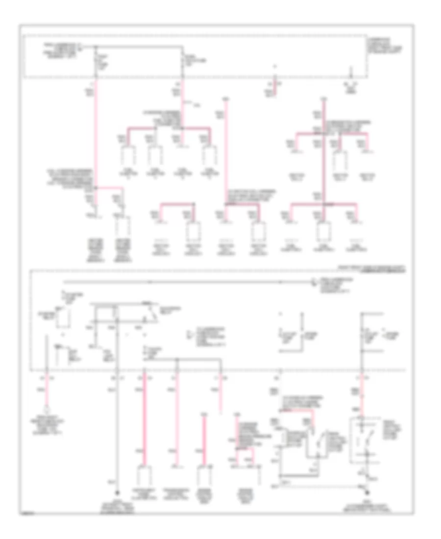
Power Distribution Wiring Diagram (2 of 7) for Cadillac STS V 2007
List of elements for Power Distribution Wiring Diagram (2 of 7) for Cadillac STS V 2007:
- (3.6l: 30 cm from ebcm connector) (4.6l: 25 cm from brake pressure sensor connector) s118
- (right front side of engine compt) underhood fuse block
- (w/ auto headlamps leveling)
- Abs fuse 50a
- Accessory relay
- Ccp fuse 10a
- Cmp clu relay
- Comp clutch fuse 10a
- Distance sensing cruise control module (w/ auto adaptive cruise control)
- Electronic brake control module (ebcm)
- Ext lights fuse 10a
- Fog lamp fuse 15a
- Fog lamp relay
- From instrument panel module (ipm) (diagram 4 of 7)
- From underhood fuse block a (blower fuse) (diagram 1 of 7)
- G104 (on right front frame rail, near bumper bracket)
- Hdlp washer circuit breaker (optional) 30a
- Head up display (hud)
- Headlamp leveling module
- Headlamp washer fluid pump fluid
- Headlamp washer fluid pump relay (w/ high intensity discharge)
- High beam relay
- Horn fuse 15a
- Horn relay
- Hud fuse 10a
- Hvac control module
- Jumper
- L rear fuse 60a
- Low beam relay/hid mini (optional)
- Outside moisture sensor (if equipped)
- Park lamp relay
- R rear fuse 60a
- R10
- R11
- R23
- R24
- R27
- R28
- R31
- R32
- R35
- R36
- R37
- R38
- R56
- Rain ssr fuse 7.5a
- S411
- Spare fuse
- Spare relay
- Tilt/ telescope switch
- Tire pressure monitor module (w/ low tire pressure indicator)
- To left rear fuse block (driver door module fuse) (diagram 5 of 7)
- To left rear fuse block (elc relay fuse) (diagram 5 of 7)
- To right rear fuse block (ign 1 relay) (diagram 7 of 7)
- To right rear fuse block (power windows motor circuit breaker) (diagram 6 of 7)
- To underhood fuse block (outlet fuse) (diagram 3 of 7)
- W/ head up display
- W/ low tire pressure indicator
- W/o low tire pressure indicator
- Windshield wiper/ washer module
- Windshield wiper/ washer switch assembly
- Wpr mod fuse 30a
- Wpr sw fuse 7.5a
Power Distribution Wiring Diagram (3 of 7) for Cadillac STS V 2007
List of elements for Power Distribution Wiring Diagram (3 of 7) for Cadillac STS V 2007:
- (3.6l: in engine harness, 52 cm from ho2s bank 1 sensor 2 connector) (4.6l: in engine harness, 34 cm from c102) s104
- (in console harness, 31 cm from hazard switch connector) s312
- (in engine harness, 16 cm from fuel injector 8 connector) s103
- (in engine harness, 39 cm from brake pressure sensor connector) s105
- (in engine poa harness, 25 cm from ignition coil 2 connector) s119
- (in ignition coil harness, 36 cm from ignition coil module 2 connector) s131
- (in passenger compt, behind right kick panel)
- (not used)
- (right front side of engine compt) underhood fuse block
- 3.6l
- 4.6l
- Cmp clu relay
- Console auxiliary power outlet
- Engine control module (ecm)
- Even coils fuse 15a
- Fog lamp relay
- From right rear fuse block (run/crank fuse, 10a) (diagram 7 of 7)
- From underhood fuse block (hud fuse) (diagram 2 of 7)
- From underhood fuse block c (pre o2/cam fuse) (diagram 1 of 7)
- Front ashtray auxiliary power outlet
- Fuel injector
- Fuel injector 2
- Fuel injector 4
- Fuel injector 6
- G104 (on right front frame rail, near bumper bracket)
- G201
- Heated oxygen sensor (ho2s) bank 1 sensor 2
- Heated oxygen sensor (ho2s) bank 2 sensor 2
- I/p outlet fuse 15a
- Ignition coil 2
- Ignition coil 4
- Ignition coil 6
- Ignition coil/ module 2
- Ignition coil/ module 4
- Ignition coil/ module 6
- Ignition coil/ module 8
- Instrument panel cluster (ipc)
- Nca
- Outlet fuse 20a
- Pnk
- Post fuse 10a
- R43
- R44
- R45
- R46
- R55
- R64
- Rear ashtray auxiliary power outlet
- Red
- Run/crank relay
- S137
- S212
- S311
- Spare fuse
- Starter fuse 30a
- Starter relay
- Tcm/ipc fuse 15a
- To underhood fuse block (wash noz/aqs fuse) (diagram 4 of 7)
- Transmission control module (tcm)
- Underhood fuse block (right front side of engine compt)
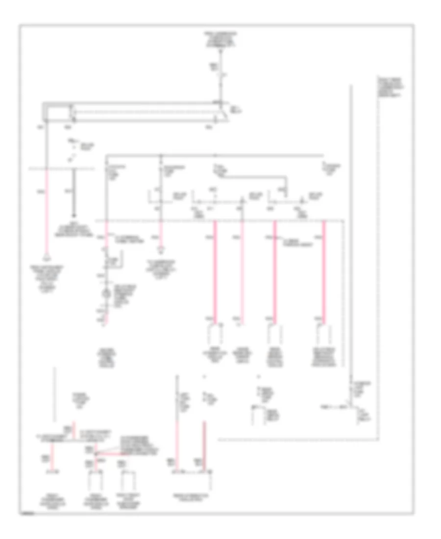
Power Distribution Wiring Diagram (4 of 7) for Cadillac STS V 2007
List of elements for Power Distribution Wiring Diagram (4 of 7) for Cadillac STS V 2007:
- (not used)
- 3.6l
- 4.4l
- Abs fuse 15a
- Acc ind
- Accessory voltage
- Accy ind cntrl
- Air quality sensor
- Ccp fuse 10a
- Electronic brake control module (ebcm)
- From underhood fuse block (run/crank relay) (diagram 3 of 7)
- Hvac control module
- Ign 1 voltage
- Ign mode sw sply volt
- Ignition mode switch
- Illum
- Instrument panel module (ipm) (right side of dash, behind glove box)
- Interior lights system
- Ipm ign mode data sig
- Ipm ign mode sw ref volt
- Left heated washer nozzle
- Maf fuse 10a
- Mass air flow (maf)/ intake air temperature (iat) sensor
- Mode control b/u
- Off
- Off in cntrl
- Off ind
- Pnk
- R63
- Rear defog relay
- Remote control door lock receiver (rcdlr) (under rear speaker shelf)
- Right heated washer nozzle
- Right rear fuse block (under right side of rear seat)
- Run ign 3 voltage
- Spare fuse
- Splice pack sp201 (on dash harness, under dashboard, near firewall grommet)
- Splice pack sp300
- Start
- Start ind
- Start ind cntrl
- Starter relay
- Starter relay fuse 10a
- To accessory relay (diagram 2 of 7)
- To ign 1 relay (diagram 7 of 7)
- To run relay (diagram 6 of 7)
- Underhood fuse block (right front side of engine compt)
- Voltage b/u
- W/ auto recircualting filter air
- W/ heated washer nozzle
- Wash noz/ aqs fuse 10a
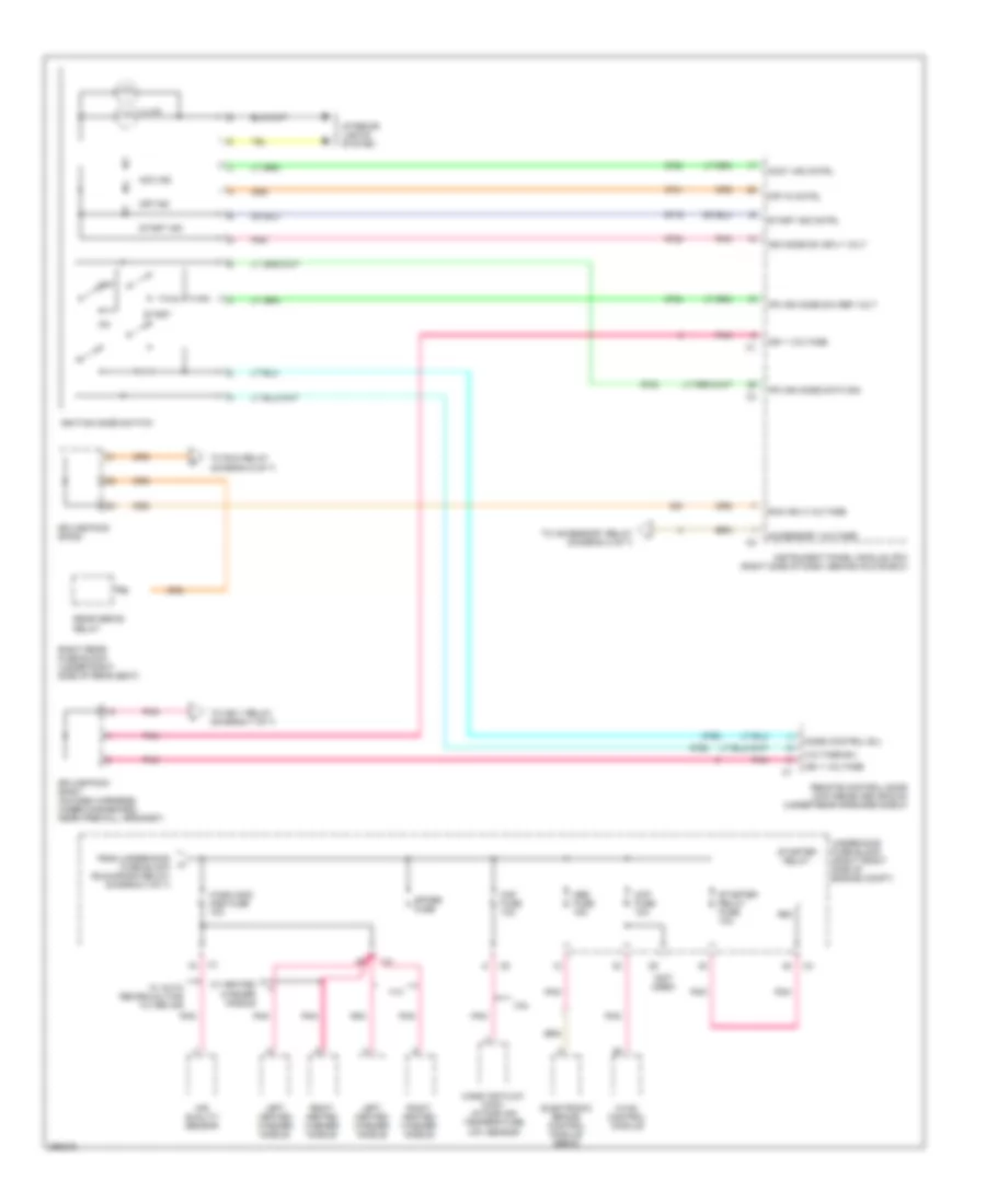
Power Distribution Wiring Diagram (5 of 7) for Cadillac STS V 2007
List of elements for Power Distribution Wiring Diagram (5 of 7) for Cadillac STS V 2007:
- (in driver door harness, 54 cm from c500) s502
- (in passenger seat harness, 17 cm from passenger seat adjuster switch connector) s354
- (under left side of rear seat) left rear fuse block
- Air bag fuse 10a
- Amp fuse 30a
- Audio amplifier (w/ infotainment system 010, 012, 014 & 015)
- Automatic level control (alc) compressor
- Automatic transmission shift lever assembly
- Dpm fuse 10a
- Driver back cooled seat blower motor
- Driver cushion cooled seat blower motor
- Driver door module (ddm)
- Driver door module fuse 15a
- Driver lumbar adjuster switch
- Driver seat adjuster switch
- Elc relay
- Elc relay fuse 30a
- Elc sol fuse 10a
- Electronic suspension control (esc) module
- From underhood fuse block (l rear fuse) (connector c2, pin 1) (diagram 2 of 7)
- From underhood fuse block (l rear fuse) (connector c2, pin 2) (diagram 2 of 7)
- Inflatable restraint sensing & diagnostic module (sdm)
- Joint connector
- Left front door subwoofer speaker
- Left position lamp relay
- Left rear door module (lrdm)
- Memory seat module (msm)
- Mr-rtd mod fuse 25a
- Nca
- Position lamp fuse 10a
- R13
- R18
- R28
- R29
- R31
- R32
- R36
- R37
- Rear dr mod fuse 15a
- Rear subwoofer speaker
- Rev lamp relay
- Reverse lamp fuse 10a
- Right position lamp relay
- Right rear door module (rrdm)
- Rr shlf speaker fuse (sub woofer) 15a
- S12
- S13
- S14
- S20
- S21
- S22 (not used)
- S23
- Spare fuse
- Splice pack
- Stndby lamp relay
- Theft/ shifter fuse 10a
- To left rear fuse block (run relay) (diagram 6 of 7)
- Trk dr rel relay
- Trunk dr/ valet fuse 10a
- Tv antenna module
- Tv/vics fuse 10a
- W/ front climate control seat
- W/ infotainment system 010
- W/ infotainment system 011,012, 014 & 015
- W/ infotainment system 012, 014 & 015
- W/ infotainment system 014 & 015
- W/ magnetic ride control
- W/ memory
- W/ power lumbar control seat
Power Distribution Wiring Diagram (6 of 7) for Cadillac STS V 2007
List of elements for Power Distribution Wiring Diagram (6 of 7) for Cadillac STS V 2007:
- (in body harness, 58 cm from right rear fuse block c1) s302
- (in body harness, 86 cm from g306) s303
- (in passenger seat harness, 24 cm from passenger seat adjuster switch connector)
- (in passenger seat harness, 32 cm from c307) s355
- (not used)
- (under right side of rear seat) right rear fuse block
- A/t shift shift lever assembly
- Cac coolant pump fuse (4.4l) 10a
- Cac coolant pump relay
- Canister vent fuse 10a
- Climate control seat module
- Digital radio receiver
- Driver window motor
- Elc relay
- Evaporative emissions (evap) canister vent solenoid
- From instrument panel module (via splice pack sp300, pin 31) (diagram 4 of 7)
- From left rear fuse block (trunk dr/ valet fuse) (diagram 5 of 7)
- From underhood fuse block (r rear fuse) (connector c3, pin 2) (diagram 2 of 7)
- Front passenger window motor
- Fuel pump (fp) relay
- Fuel pump fuse 15a
- G402 (in rear compt, to rear of left rear shock tower)
- Ign 3 fuse 10a
- Left front seat belt retractor
- Left rear fuse block (under left side of rear seat)
- Left rear window motor
- Memory seat module (msm)
- Passenger back cooled seat blower motor
- Passenger climate control seat module
- Passenger cushion cooled seat blower motor
- Passenger lumbar adjuster switch
- Passenger seat adjuster switch
- R12
- R21
- R22
- R23
- R25
- R37
- Radio
- Radio/ onstar fuse 10a
- Rear heated seat fuse 20a
- Rear heated seat module
- Rear integration module (rim)
- Rf htd st/ s-band fuse 20a
- Right front seat belt retractor
- Right rear window motor
- Right turn-rim fuse 10a
- Run relay
- S15
- S16
- S17
- S353
- Seats circuit breaker 30a
- Spare fuse
- Splice pack
- Stop lamp relay
- Stop lamps fuse 10a
- Sunroof control module
- Sunroof fuse 20a
- Vehicle communication interface module (vcim)
- W/ digital radio
- W/ front heated & cooling seats
- W/ front heated seat
- W/ power lumbar control seats
- W/ rear heated seat
- W/o power lumbar control seats
- Window mtrs circuit breaker 30a
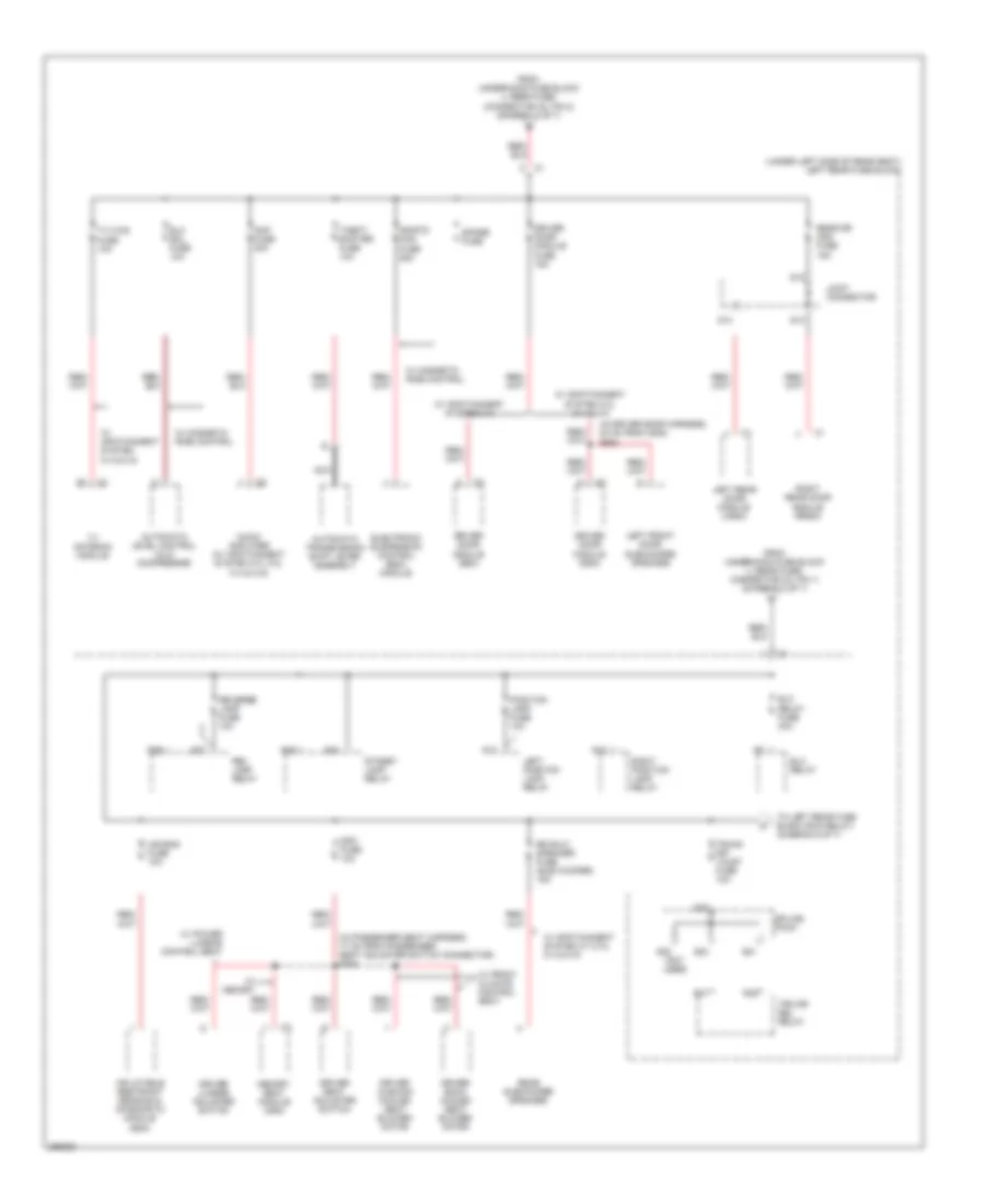
Power Distribution Wiring Diagram (7 of 7) for Cadillac STS V 2007
List of elements for Power Distribution Wiring Diagram (7 of 7) for Cadillac STS V 2007:
- (in passenger door harness, 34 cm from front passenger window motor connector)
- Air bag fuse 10a
- D pnk
- From instrument panel module (via splice pack sp201, pin 10) (diagram 4 of 7)
- From underhood fuse block (r rear fuse) (diagram 2 of 7)
- Front passenger door module (fpdm)
- Fuse 7.5a
- G401 (in rear compt, to rear of right rear shock tower)
- Heated steering wheel control module
- Htd stg/ clm fuse 15a
- Ign 1 relay
- Inflatable restraint sensing & diagnostic module (sdm)
- Inflatable restraint steering wheel module coil
- Inside rearview mirror (isrvm)
- Int lamp relay
- Interior lamp fuse 10a
- Left turn rim fuse 10a
- Nca
- Pnk
- Psgr dr mod fuse 15a
- R16
- R17
- R21
- R22
- R23
- R25
- Rear defog fuse 40a
- Rear defog relay
- Rear integration module (rim)
- Rear object sensor control module
- Right front door subwoofer speaker
- Right rear fuse block (under right side of rear seat)
- Rim fuse 10a
- Run/crank fuse 10a
- S10 (not used)
- S11
- S22
- S23 (not used)
- S25
- Splice pack
- To underhood fuse block (cmp clu relay) (diagram 3 of 7)
- W/ infotainment system 010
- W/ infotainment system 012, 011, 014 & 015
- W/ rear parking assist
- W/ steering wheel heater

 Čeština
 Dansk
Dansk Deutsch
 Ελληνικά
 English
 English
 Español
 Suomi
Suomi Français
 Français
 עברית
עברית Hrvatski
 Magyar
 Italiano
 日本語
日本語 한국어
한국어 Nederlands
 Polski
 Português
 Română
 Русский
 Slovenčina
 Slovenščina
 Svenska
 Türkçe
 中文 (中国)