POWER DISTRIBUTION
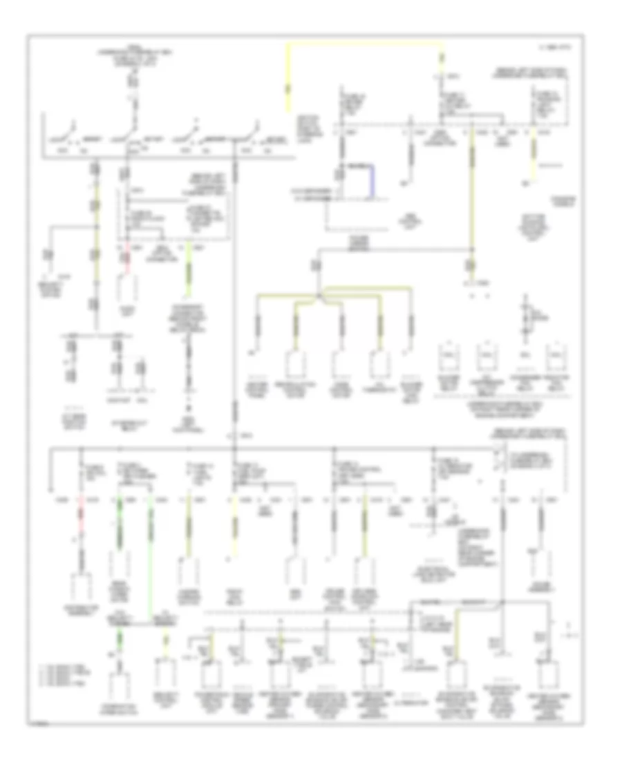
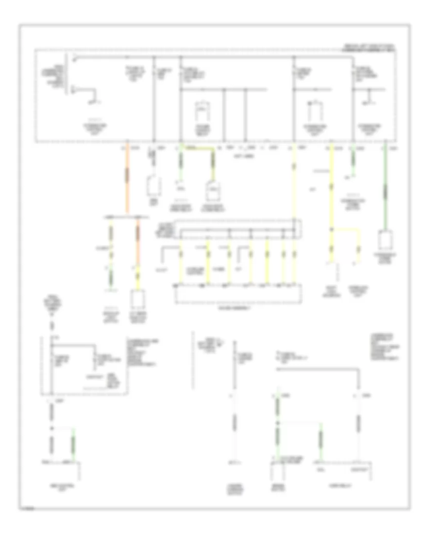
Power Distribution Wiring Diagram (1 of 3) for Honda Civic DX 1999
 https://portal-diagnostov.com/license.html
Automotive Electricians Portal FZCO
Automotive Electricians Portal FZCO
https://portal-diagnostov.com/license.html
https://portal-diagnostov.com/license.html
Automotive Electricians Portal FZCO
Automotive Electricians Portal FZCO
List of elements for Power Distribution Wiring Diagram (1 of 3) for Honda Civic DX 1999:
- (ex vtec-e w/ m/t)
- (on right rear corner of engine compartment) underhood fuse/relay box
- (sedan) 1
- (vtec-e w/ m/t)
- A/c compressor clutch relay
- A/t
- Alternator
- Audio unit
- B10
- B21
- Battery
- Blower motor relay
- C 1995 vftc
- C10
- C351
- C352
- C419
- C420
- C422
- C551
- C712
- C926 (option connector)
- Canadian models
- Ceiling light
- Combination light switch
- Condenser fan relay
- Contact
- Data link connector (dlc) (partial)
- Daytime running lights (drl) control unit
- Electrical load detector (eld) unit
- From underhood fuse/relay box (fuse 48 headlight, 30a) (diagram 1 of 3)
- Fuse 1 (not used)
- Fuse 2 (not used)
- Fuse 20 running light 7.5a
- Fuse 33 interlock unit 7.5a
- Fuse 41 battery 80a
- Fuse 42 ig1 40a
- Fuse 43 interior light 7.5a
- Fuse 44 fi e/m 15a
- Fuse 46 power window 40a
- Fuse 47 back up 7.5a
- Fuse 48 headlight 30a
- Fuse 50 rear defogger 30a
- Fuse 51 door lock unit, roof 20a
- Fuse 54 option 40a
- Fuse 55 heater motor 40a
- Fuse 56 condenser fan 20a
- Fuse 57 cooling fan 20a
- Fuse 6 3a
- Heater control panel
- Integrated control unit
- Keyless door lock control unit
- Moon roof close relay
- Moon roof open relay
- Not used
- Pgm-fi main relay
- Power door lock control unit
- Power window relay
- Powertrain control module (pcm) or engine control module (ecm)
- Radiator fan relay
- Rear window defogger relay
- Security control unit connector (option)
- Security system connector (option)
- Spot lights
- Starter
- Starter solenoid
- Steering lock
- T101
- T102
- To ignition switch (diagram 2 of 3)
- To underhood abs fuse/relay box (diagram 3 of 3)
- To underhood fuse/relay box (fuse 53 hazard, 10a) (diagram 3 of 3)
- To underhood fuse/relay box (fuse 55 heater motor, 40a) (diagram 1 of 3)
- Trunk light
- Underdash fuse/relay box (behind left side of dash)
- Underdash fuse/relay box (behind left side of dash)
- Underhood fuse/relay box (on right rear corner of engine compartment)
- Us models: lx, ex, hx, dx-v, & si canadian models: ex & si
- W/ keyless entry
- W/o keyless entry
Power Distribution Wiring Diagram (2 of 3) for Honda Civic DX 1999
List of elements for Power Distribution Wiring Diagram (2 of 3) for Honda Civic DX 1999:
- (behind left side of dash) underdash fuse/relay box
- (canada)
- (not used)
- (us)
- (w/ defogger)
- (w/o defogger)
- 1.6l dohc vtec 1.6l sohc vtec-e
- 1.6l sohc 1.6l sohc vtec
- A/c compressor clutch relay
- A/c diode
- A/c thermostat
- A/t
- A/t gear position switch
- Abs control unit
- Acc
- Accessory connector (behind front console, below radio)
- Alternator
- Audio unit
- B15
- Blower motor high relay
- Blower motor relay
- C 1995 vftc
- C352
- C416
- C419
- C420
- C421
- C423
- C439
- C501
- C551
- C801
- C913
- C928 (option connector)
- C929 (option connector)
- Canadian models
- Coil
- Combination wiper switch
- Condenser fan relay
- Contact
- Cruise control main switch
- Daytime running lights (drl) control unit
- Distributor assembly
- Electrical load detector (eld) unit
- Evaporative emission (evap) bypass solenoid valve
- Evaporative emission (evap) control canister vent shut valve
- Evaporative emission (evap) purge control solenoid valve
- Except vtec-e m/t
- From underhood fuse/relay box (fuse 42 ig1, 40a) (diagram 1 of 3)
- Fuse 12 turn lights 7.5a
- Fuse 13 fuel pump (srs unit) 15a
- Fuse 14 cruise control (keyless) 7.5a
- Fuse 15 alternator (sp sensor) 7.5a
- Fuse 16 rr def relay 7.5a
- Fuse 17 heater a/c relay 7.5a
- Fuse 18 (running light relay) 7.5a
- Fuse 27 cigarette lighter acc socket 10a
- Fuse 28 radio clock 10a
- Fuse 3 rr wiper (rr washer) 10a
- Fuse 9 ign coil 15a
- G200 (left kick panel)
- Gauge assembly
- Hazard warning switch
- Heated oxygen sensor (primary h02s) (sensor 1)
- Heated oxygen sensor (secondary h02s) (sensor 2)
- Heater control panel
- Ignition switch (part of steering lock)
- J/c c115 (left rear of engine)
- Keyless doorlock control unit
- Lock
- M/t
- Mode control motor
- Pgm-fi main relay
- Power mirror switch
- Powertrain control module (a/t)
- Radiator fan relay
- Rear window wiper motor
- Recirculation control motor
- Red
- Security control unit
- Security system option
- Srs unit
- Start
- Starter cut relay
- To underdash fuse/relay box (diagram 3 of 3)
- Underhood fuse/relay box (on right rear corner of engine compartment)
- Us models
- Vehicle speed sensor (vss)
- W/ security system
- W/o security system
Power Distribution Wiring Diagram (3 of 3) for Honda Civic DX 1999
List of elements for Power Distribution Wiring Diagram (3 of 3) for Honda Civic DX 1999:
- (behind left side of dash) underdash fuse/relay box
- (not used)
- (w/o cruise) (w/ cruise)
- 15 or 6
- A/t
- A/t gear position switch
- Abs control unit
- Abs pump motor relay
- B14
- B15
- Back-up light switch
- Brake switch
- C352
- C353
- C357
- C419
- C420
- C421
- C423
- C501
- C712
- C801
- Coil
- Combination wiper switch
- Contact
- From battery (diagram 1 of 3)
- From battery b (diagram 1 of 3)
- From underdash fuse/relay box (diagram 2 of 3)
- Fuse 19 back up lights 7.5a
- Fuse 23 srs 10a
- Fuse 24 (p/w relay) (s/r relay) 7.5a
- Fuse 25 meter 7.5a
- Fuse 26 fr wiper fr washer 20a
- Fuse 52 horn, stop lt 15a
- Fuse 53 hazard 10a
- Fuse 61 pump motor 40a
- Fuse 62 abs +b 20a
- Gauge assembly
- Hazard warning switch
- Horn relay
- Integrated control unit
- Interlock control unit
- J/c c507 (behind left side of dash)
- M/t
- Moon roof close relay
- Moon roof open relay
- Power window relay
- Shift lock solenoid
- Srs unit
- Underhood abs fuse/relay box (on right side of engine compartment)
- Underhood fuse/relay box (on right rear corner of engine compartment)
- W/ m/t
- W/abs
- W/cruise control
- Windshield wiper motor

 Čeština
 Dansk
Dansk Deutsch
 Ελληνικά
 English
 English
 Español
 Suomi
Suomi Français
 Français
 עברית
עברית Hrvatski
 Magyar
 Italiano
 日本語
日本語 한국어
한국어 Nederlands
 Polski
 Português
 Română
 Русский
 Slovenčina
 Slovenščina
 Svenska
 Türkçe
 中文 (中国)