WARNING SYSTEMS
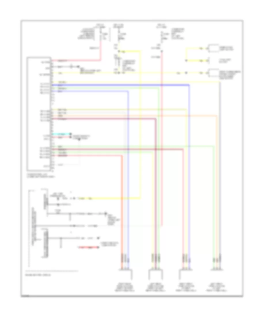
Tire Pressure Monitoring Wiring Diagram for Honda Ridgeline RTS 2009
List of elements for Tire Pressure Monitoring Wiring Diagram for Honda Ridgeline RTS 2009:
- +b tpms
- A10
- A19
- A20
- Auxiliary under-hood fuse box (left side of engine compt)
- Can h
- Can l
- Combination light switch
- Computer data lines system
- Fast controller area network transceiver
- Fl ini sig
- Fl lf gnd
- Fl lf ini+
- Fr ini sig
- Fr lf gnd
- Fr lf ini+
- Front passenger's power window switch/door lock switch
- Fuse 7.5a
- G401 (behind upper left end of dash)
- Gauge control module
- Gnd
- Hot at all times
- Hot in on or start
- Ig1 meter
- K-line
- Left front tpms initiator (in left front wheelwell)
- Left rear tpms initiator (front of left rear wheelwell)
- Low tire pressure ind
- N38
- Red
- Right front tpms initiator (in right front wheelwell)
- Right rear tpms initiator (front of right rear wheelwell)
- Rl ini sig
- Rl lf gnd
- Rl lf ini+
- Rr ini sig
- Rr lf gnd
- Rr lf ini+
- Tpms control unit (under left side of dash)
- Tpms ind
- Under-dash fuse/relay box (at left kick panel)
- Vtm-4 lock switch
- Warning drive circuit
- X34
- X35
 Čeština
 Dansk
Dansk Deutsch
 Ελληνικά
 English
 English
 Español
 Suomi
Suomi Français
 Français
 עברית
עברית Hrvatski
 Magyar
 Italiano
 日本語
日本語 한국어
한국어 Nederlands
 Polski
 Português
 Română
 Русский
 Slovenčina
 Slovenščina
 Svenska
 Türkçe
 中文 (中国)
 Português