ANTI-LOCK BRAKES
Anti-lock Brakes Wiring Diagram for Ford Five Hundred SE 2005
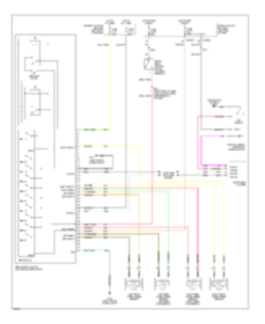
List of elements for Anti-lock Brakes Wiring Diagram for Ford Five Hundred SE 2005:
- (left bottom of dash) g202
- (right front of eng compt)
- Abs control module (left rear of eng compt)
- Abs module
- Abs pump motor
- Battery junction box (bjb) (left front of engine)
- Brake pedal position switch (on pedal assembly)
- C2280a
- C2280e
- Computer data lines system
- Fuse f1.10 40a
- Fuse f1.13 20a
- Fuse f2.18 10a
- Fuse f2.19 10a
- G101
- G105 (right front of eng compt)
- Gnd
- Hot at all times
- Hot in start or run
- Hs can +
- Hs can -
- Instrument cluster
- Left front +
- Left front -
- Left front wheel speed sensor
- Left rear +
- Left rear -
- Left rear wheel speed sensor (left rear hub assembly)
- Nca
- Red/pnk
- Right front +
- Right front -
- Right front wheel speed sensor
- Right rear +
- Right rear -
- Right rear wheel speed sensor (right rear hub assembly
- S203
- S311
- Smart junction box (sjb) (left side of dash)
- Tcs enable
- Tcs on
- Tcs sig
- To c2227)
- Traction assist/ parking aid disable switch
- Vpwr
 Čeština
 Dansk
Dansk Deutsch
 Ελληνικά
 English
 English
 Español
 Suomi
Suomi Français
 Français
 עברית
עברית Hrvatski
 Magyar
 Italiano
 日本語
日本語 한국어
한국어 Nederlands
 Polski
 Português
 Română
 Русский
 Slovenčina
 Slovenščina
 Svenska
 Türkçe
 中文 (中国)
 Português