ANTI-LOCK BRAKES
Anti-lock Brake Wiring Diagrams for Mercury Cougar 2002
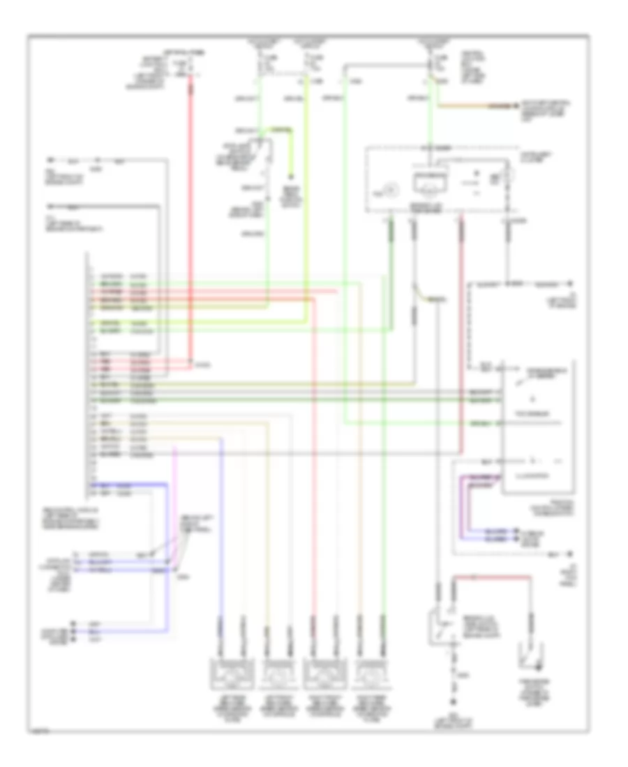
List of elements for Anti-lock Brake Wiring Diagrams for Mercury Cougar 2002:
- (behind left side of dash panel)
- 15-cf6
- 15s-cf58
- 30-cf6a
- 30-cf6b
- 31-cf6a
- 31-cf6b
- 31s-cf28
- 31s-cf45
- 31s-cf45a
- 31s-cf54
- 31s-gc6a
- 4-cf6
- 5-cf6
- 8-cf29
- 8-cf32
- 8-cf34
- 8-cf38
- 8-cf40
- 9-cf32
- 9-cf34
- 9-cf38
- 9-cf40
- Abs control module (left rear of engine compartment, near brake booster)
- Abs ind
- Anti-theft/central locking module, gearshift lever unit
- Brake fluid level switch (left rear of engine compt)
- Brake fluid/ park brake
- Brake pedal position switch
- C362
- C365
- C369
- C808b
- Central junction box (under left side of dash)
- Computer data lines system
- Connector (dlc) (under center of dash)
- Data link
- Disable/enable switch
- Fuse 15a
- Fuse 60a
- Fuse 7.5a
- G1 (left front of engine)
- G11 (left rear of engine compartment)
- G22 (left front of engine compt)
- G7 (right kick panel)
- Hot at all times battery junction box (left front corner of engine compt)
- Hot in start or run
- Illumination
- Instrument cluster
- Interior lights system
- Left front abs wheel speed sensor (on spindle)
- Left rear abs wheel speed sensor (on backing plate)
- Nca
- Park brake switch (at base of park brake lever)
- Processor
- Red
- Right front abs wheel speed sensor (on spindle)
- Right rear abs wheel speed sensor (on backing plate)
- S1002
- S281
- S282
- S359
- S360
- S363
- S364
- S367 (behind left side of dash)
- Stoplamp switch (on bracket above brake pedal)
- Tcs
- Tcs disabled
- Traction control system disable switch
 Čeština
 Dansk
Dansk Deutsch
 Ελληνικά
 English
 English
 Español
 Suomi
Suomi Français
 Français
 עברית
עברית Hrvatski
 Magyar
 Italiano
 日本語
日本語 한국어
한국어 Nederlands
 Polski
 Português
 Română
 Русский
 Slovenčina
 Slovenščina
 Svenska
 Türkçe
 中文 (中国)
 Português