ANTI-THEFT
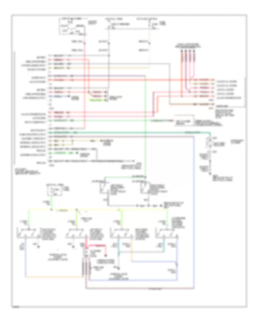
Anti-theft Wiring Diagram for Ford Pickup F350 1993
List of elements for Anti-theft Wiring Diagram for Ford Pickup F350 1993:
- alarm indicator output
- (behind bottom of left kick panel) g200
- (lower rear of door) left rear courtesy lamp switch
- Acc
- Anti-theft controller module (behind left side of i/p)
- Anti-theft indicator
- Battery
- C237
- C238
- C241
- C242
- C251
- Circuit breaker 20a
- Courtesy lamp diode
- Courtesy lamps input
- Crew cab only
- Disarm input
- Door ajar
- Door locks system (remote keyless entry)
- Exterior lamps output
- Exterior lights system
- Fuse 15a
- Fuse panel
- G203 (behind bottom of right cowl panel)
- Ground
- Headlamps enable
- Headlights system
- Horn enable output
- Horns system
- Hot at all times
- Hot in accy or run
- Ignition input
- Ignition switch
- Instrument cluster
- Interior lights system (courtesy lights)
- Key cylinder input
- Key cylinder sensor
- Left front courtesy lamp switch (on front of door jamb)
- Left front door disarm switch (in left front door)
- Liftgate jamb sw input
- Lock
- Lock all doors
- Lock doors
- Nca
- Off
- Red/ pnk
- Red/pnk
- Remote keyless entry module (behind left side of i/p)
- Right front courtesy lamp switch (on front of door jamb)
- Right front door disarm switch (in right front door)
- Right rear courtesy lamp switch (lower rear of door)
- Run
- Run/accy power
- Speed control/ horn switch assembly (cruise control system)
- Sta
- Start
- Starter motor output
- Starting system
- Unlock all doors
- Unlock doors
- Unlock driver's door
- Warning system (warning chime)
 Čeština
 Dansk
Dansk Deutsch
 Ελληνικά
 English
 English
 Español
 Suomi
Suomi Français
 Français
 עברית
עברית Hrvatski
 Magyar
 Italiano
 日本語
日本語 한국어
한국어 Nederlands
 Polski
 Português
 Română
 Русский
 Slovenčina
 Slovenščina
 Svenska
 Türkçe
 中文 (中国)
 Português