BODY CONTROL MODULES
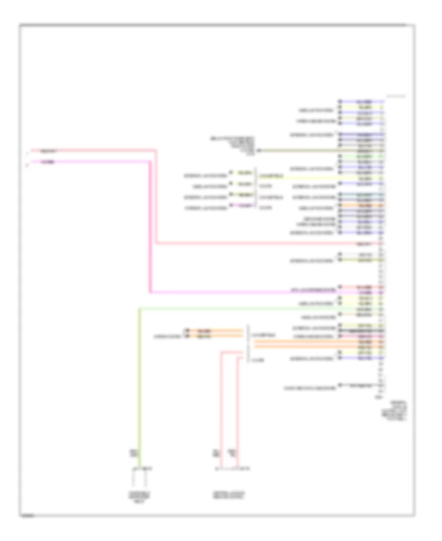
Body Control Modules Wiring Diagram (1 of 2) for MINI Cooper 2007
 https://portal-diagnostov.com/license.html
Automotive Electricians Portal FZCO
Automotive Electricians Portal FZCO
https://portal-diagnostov.com/license.html
https://portal-diagnostov.com/license.html
Automotive Electricians Portal FZCO
Automotive Electricians Portal FZCO
List of elements for Body Control Modules Wiring Diagram (1 of 2) for MINI Cooper 2007:
- Air conditioning system
- Anti-theft system
- Computer data lines system
- Cruise control system
- Door locks system
- Exterior lights system
- Fuse f1 30a
- Fuse f14 10a
- Fuse f19 30a
- Fuse f4 5a
- Fuse f7 5a
- Fuse fl 12 50a
- Fuse fl 8 50a
- Fuse holder 2 (behind left footwell trim)
- Fuse holder 3 (left side of engine compt)
- Fuse f32 20a
- General module control unit (behind right footwell)
- Headlights system
- Hot at all times
- Hot in accy, run and start
- Interior lights system
- Power windows system
- Power windows systems
- Red
- Wiper/washer system
- X10201
- X10202
- X10206
- X10207
- X151 (right side of right footwell)
- X253
- X255
- X332
- X4009
- X4010
Body Control Modules Wiring Diagram (2 of 2) for MINI Cooper 2007
List of elements for Body Control Modules Wiring Diagram (2 of 2) for MINI Cooper 2007:
- (below right rear seat) (convertible) (right door) (coupe) x179
- Anti-lock brakes system
- Central locking remote control
- Computer data lines system
- Convertible
- Coupe
- Defogger system
- Exterior lights system
- General module control unit (behind right footwell)
- Headlights system
- Interior lights system
- Mirror system
- Windshield defroster relay
- Wiper/washer system
- X1143
- X254
- X3148

 Čeština
 Dansk
Dansk Deutsch
 Ελληνικά
 English
 English
 Español
 Suomi
Suomi Français
 Français
 עברית
עברית Hrvatski
 Magyar
 Italiano
 日本語
日本語 한국어
한국어 Nederlands
 Polski
 Português
 Română
 Русский
 Slovenčina
 Slovenščina
 Svenska
 Türkçe
 中文 (中国)