ENGINE PERFORMANCE
3.5L TWIN TURBO
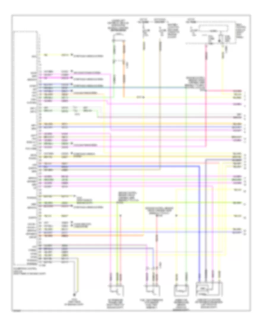
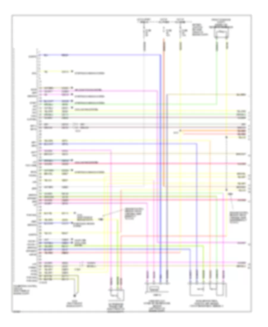
3.5L Twin Turbo, Engine Performance Wiring Diagram (1 of 6) for Ford F-150 XLT 2013
 https://portal-diagnostov.com/license.html
Automotive Electricians Portal FZCO
Automotive Electricians Portal FZCO
https://portal-diagnostov.com/license.html
https://portal-diagnostov.com/license.html
Automotive Electricians Portal FZCO
Automotive Electricians Portal FZCO
List of elements for 3.5L Twin Turbo, Engine Performance Wiring Diagram (1 of 6) for Ford F-150 XLT 2013:
- (fuel tank assembly) fuel tank pressure (ftp) sensor
- A/c pressure transducer (right front of engine compt)
- Aat
- Accelerator pedal position (app) sensor (top of brake pedal assembly)
- Accr
- Acpt
- Air conditioning system
- App1
- App2
- Apprtn
- Apprtn2
- Appvref
- Appvref2
- Body control module (right kick panel)
- Bpp
- C146
- C1551b
- C1581
- C192
- C214
- C2280f
- Cact
- Canv
- Cbb53
- Ccb08
- Cdc10
- Cdc12
- Cdc15
- Cdc35
- Cdc54
- Ce113
- Ce114
- Ce233
- Ce234
- Ce436
- Ce607
- Cec01
- Cec02
- Ch302
- Computer data lines system
- Cooling fans system
- Evapcp
- Fpc
- Fpm
- Ftpref
- Fuse 10a
- Gencom
- Generator current sensor (right front corner of engine compt)
- Genmon
- Heated oxygen sensor (ho2s) 12 (engine exhaust pipe)
- Heated oxygen sensor (ho2s) 22 (engine exhaust pipe)
- Hfc
- Ho2s12
- Ho2s22
- Hot at all times
- Hs can +
- Hs can -
- Htr12
- Htr22
- Ispr
- Le136
- Le137
- Le230
- Le424
- Lfc
- Micro
- Passive anti-theft transceiver (ignition switch assembly)
- Pcm wake
- Pcm wake up (fet)
- Pcmrc
- Powertrain control module (pcm) (right rear of engine compt)
- Re136
- Re137
- Re145
- Re332
- Re405
- Re407
- S140
- S141
- S240 (engine control sensor wiring harness, near breakout to body control module)
- Sigrtn
- Smc
- Smcs
- Start
- Starting/ charging system
- Starting/charging system
- Vdb04
- Vdb05
- Ve225
- Ve518
- Ve701
- Ve702
- Ve731
- Ve733
- Ve750
- Vh433
- Vref
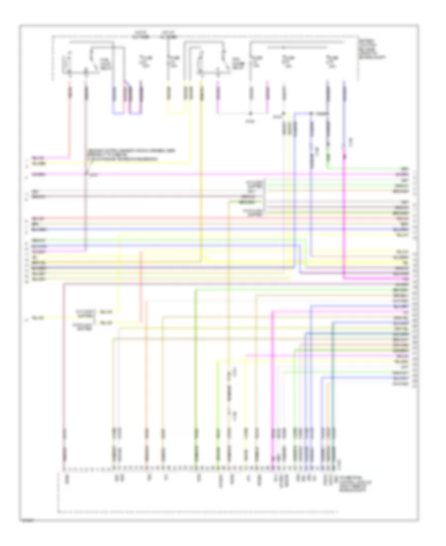
3.5L Twin Turbo, Engine Performance Wiring Diagram (2 of 6) for Ford F-150 XLT 2013
List of elements for 3.5L Twin Turbo, Engine Performance Wiring Diagram (2 of 6) for Ford F-150 XLT 2013:
- (engine control sensor wiring harness, near breakout to g101) s169
- (under left center of vehicle) evaporative emission (evap) canister vent solenoid
- 10a
- 50a
- Ambient air temperature sensor (front of engine compt)
- Battery junction box (bjb) (front of engine compt)
- Brake pedal position (bpp) switch (left side of dash)
- C-vref
- C146
- C1581
- C211
- C264
- Cact
- Fuse
- Fuse 10a
- Fuse 15a
- Fuse 20a
- Fuse 25a
- Fuse 5a
- Hot at all times
- Hot in run or start
- Nca
- Pcm power relay
- Power distribution system
- R/s
- S101
- S105
- S112
- S121
- S125
- S129
- S167 (engine control sensor wiring harness, near breakout to c110)
- Sigrtn
- Sst-d
- Sst-u
- Tcbp
- Tow haul switch (w/ column shifter)
- Tows
- Turbocharger boost pressure/ charge air cooler temperature sensor (left side of engine)
- W/ column shifter
- W/ floor shifter
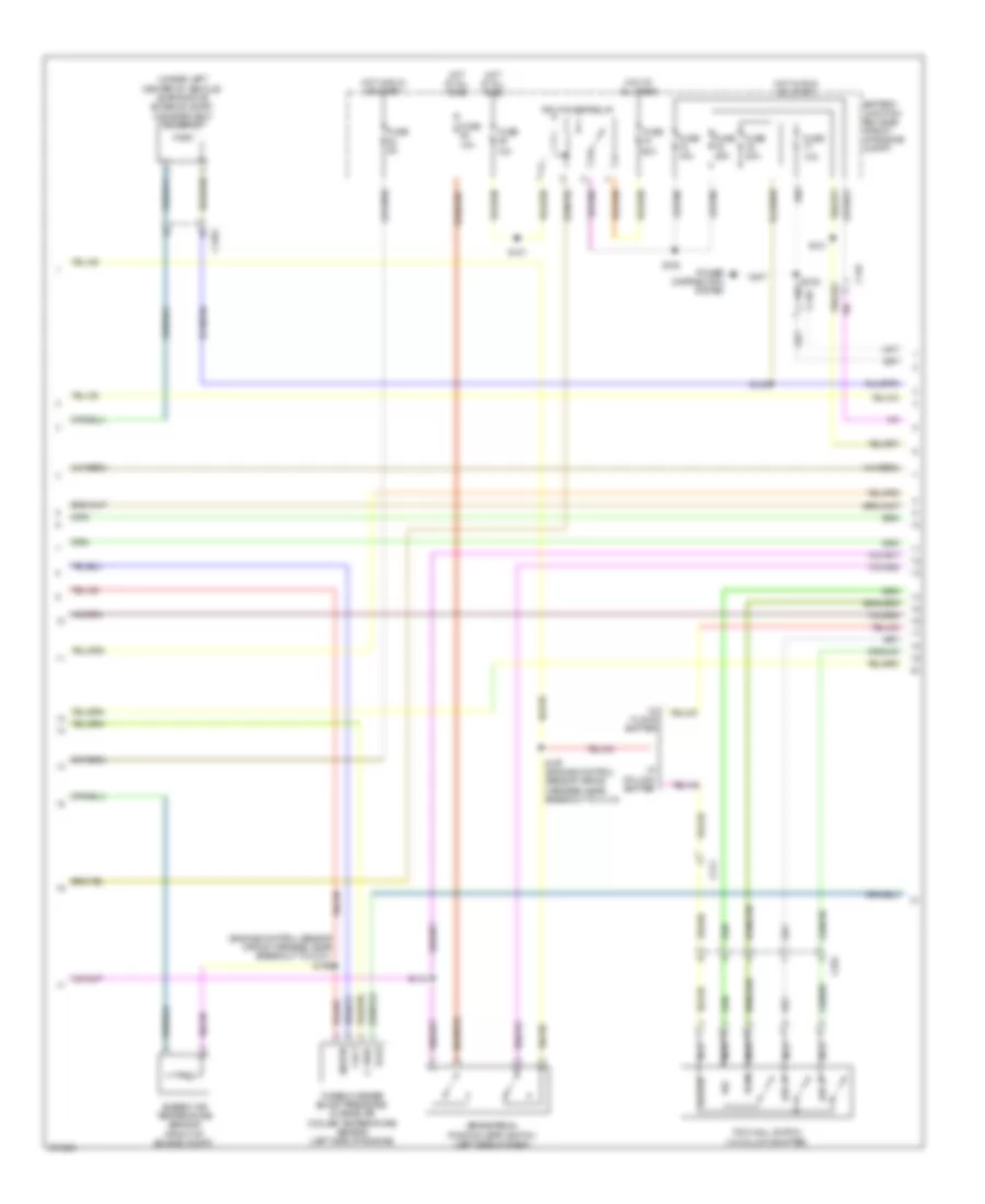
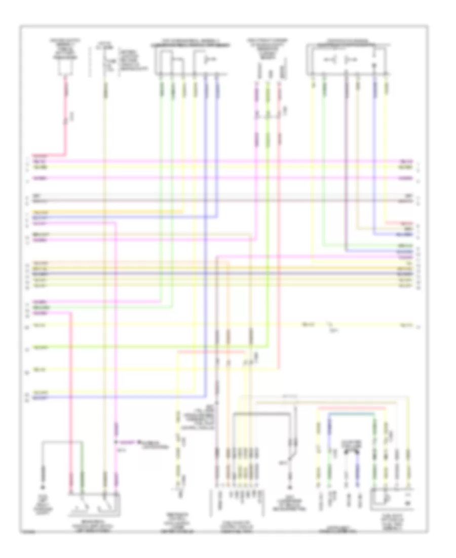
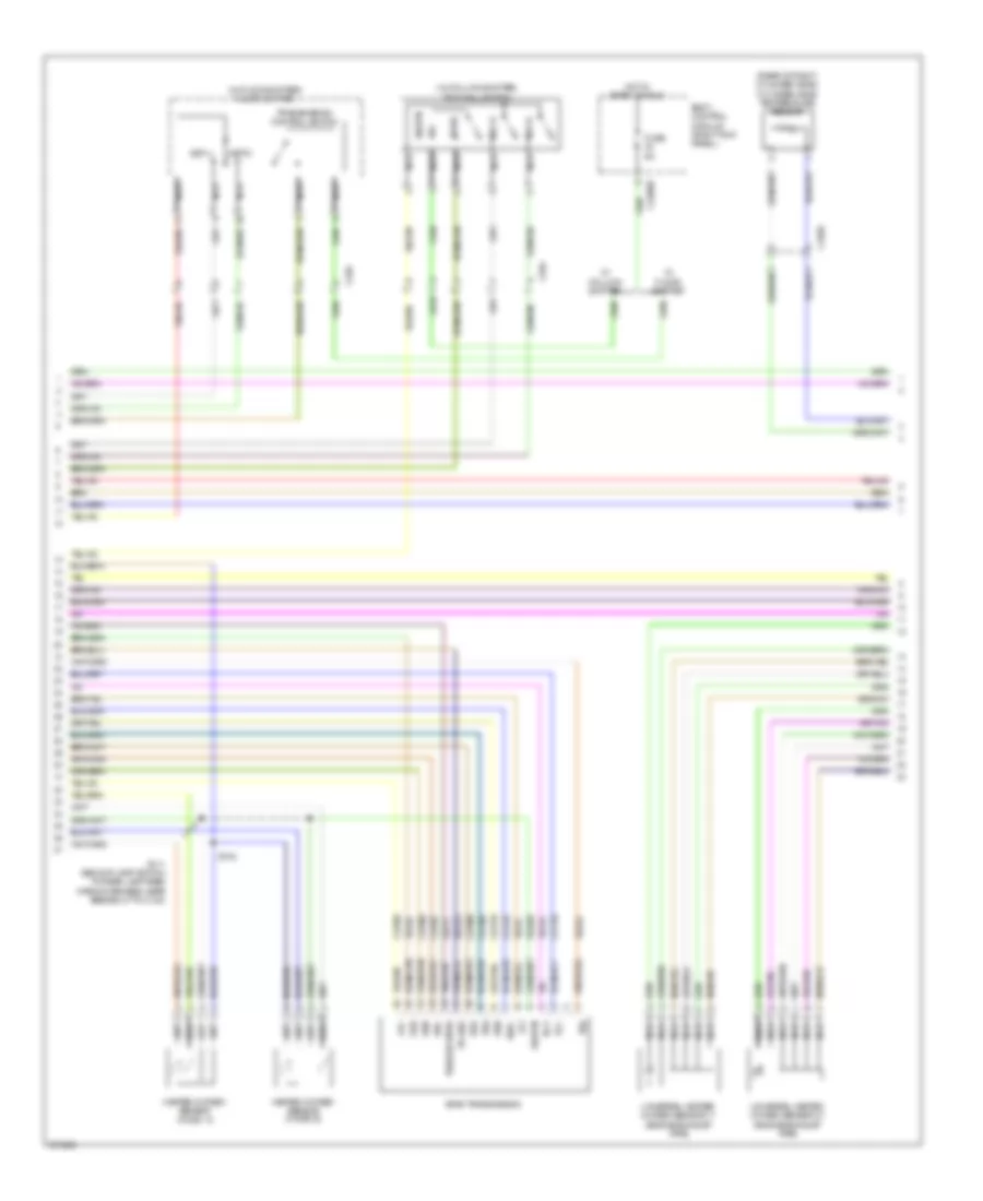
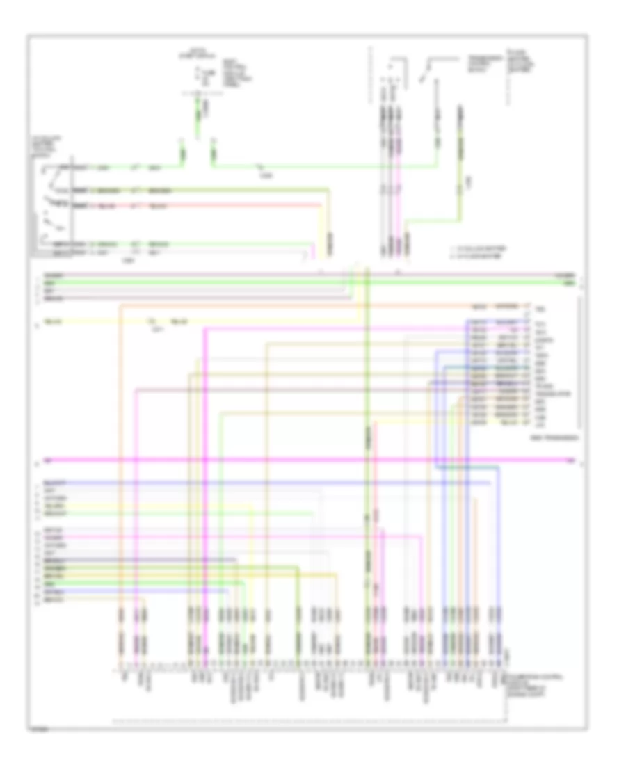
3.5L Twin Turbo, Engine Performance Wiring Diagram (3 of 6) for Ford F-150 XLT 2013
List of elements for 3.5L Twin Turbo, Engine Performance Wiring Diagram (3 of 6) for Ford F-150 XLT 2013:
- (w/ floor shifter) floor shifter
- Bcs2 alt
- Body control module (right kick panel)
- Bps
- C-vref
- C1551b
- C1551e
- C210
- C211
- C213
- C214
- C2280b
- C2280f
- C329
- Cbb75
- Ccb08
- Ce205
- Ce206
- Ce207
- Ce208
- Ce209
- Ce210
- Ce226
- Ce305
- Ce308
- Ce412
- Ce426
- Ces09
- Cet07
- Cet25
- Cet34
- Cet42
- Cet43
- Cop3e
- Cop6f
- Ftp
- Fuel pump (fet)
- Fuse 5a
- Fvr
- Fvrrtn
- G100 (right side of engine compt)
- Gd113
- Hot in start or run
- Iat
- Iat1
- Inj1
- Inj1rtn
- Inj2
- Inj2rtn
- Inj3
- Inj3rtn
- Inj4
- Inj4rtn
- Inj5
- Inj5rtn
- Inj6
- Inj6rtn
- Micro
- Nca
- Powertrain control module (pcm) (right rear of engine compt)
- Pwrgnd
- Re150
- Re205
- Re206
- Re207
- Re208
- Re209
- Re210
- Re226
- Re804
- S103
- Sigrtn
- Ssc
- Sst d
- Sst u
- Sst-d
- Sst-u
- Starting/ charging system
- Tacm+
- Tacm-
- Tcbp
- Tcip
- Ticp
- Tows
- Transmission control switch
- Tspc
- Turbocharger intake pressure & temperature (tcipt) sensor
- Vdc61
- Ve804
- Ve922
- Vpwr
- W/ column shifter
- W/ floor shifter
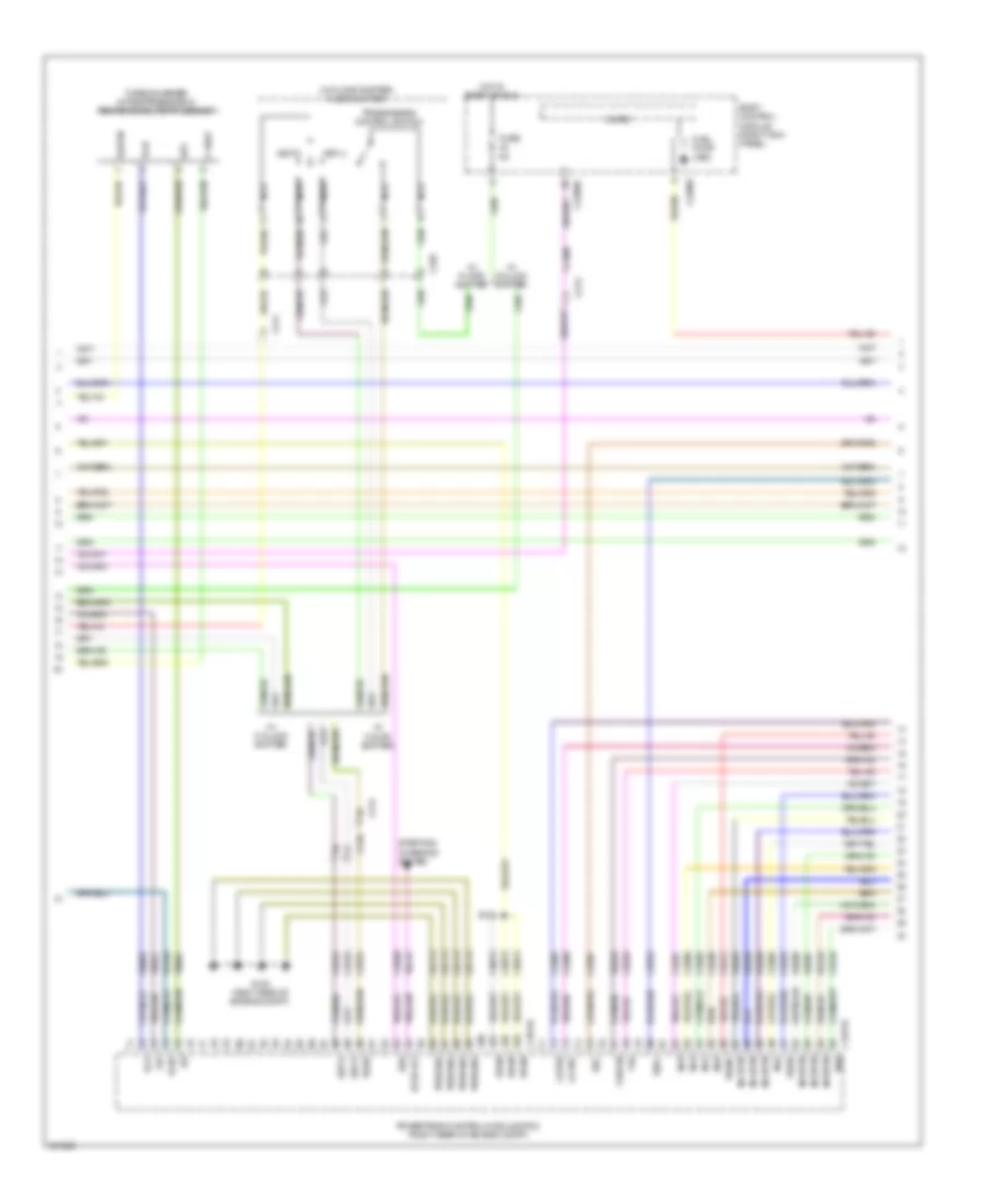
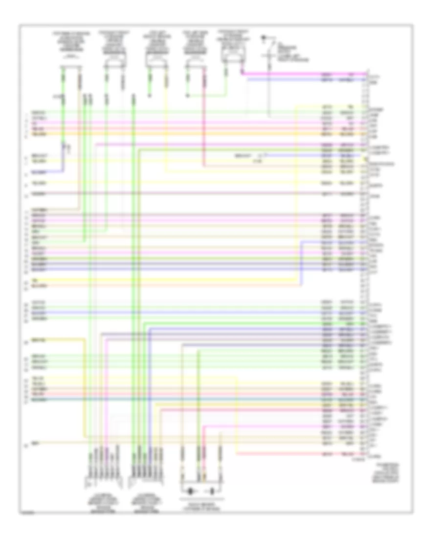
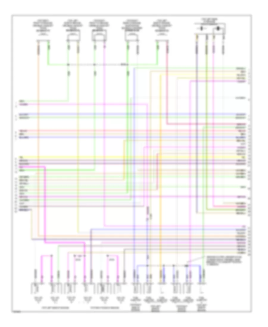
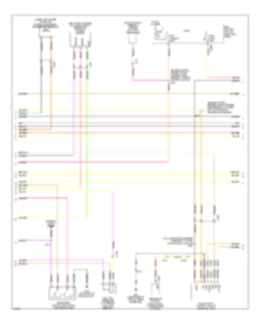
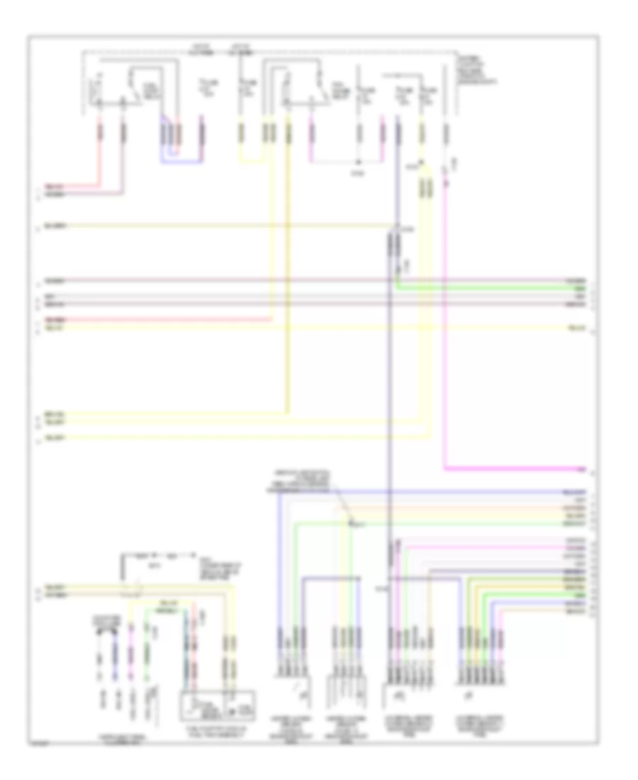
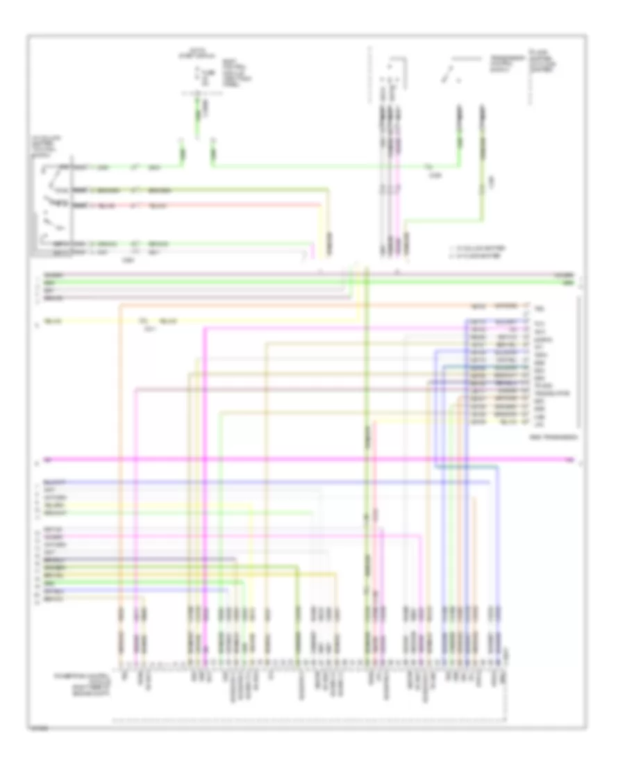
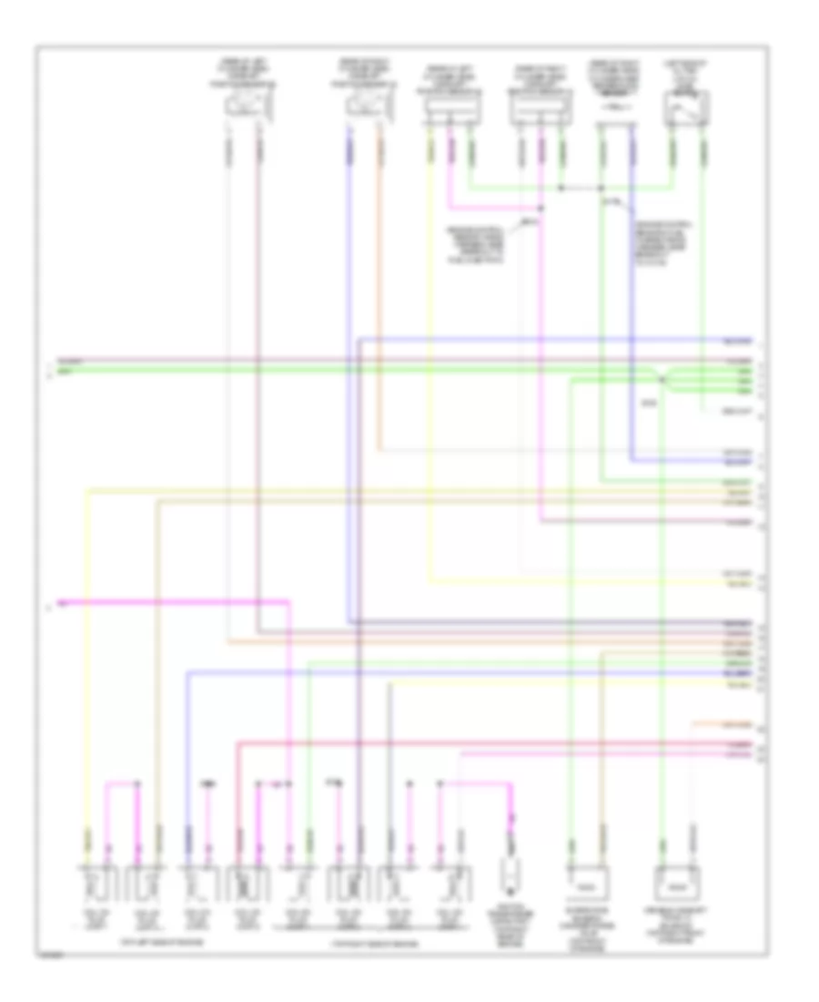
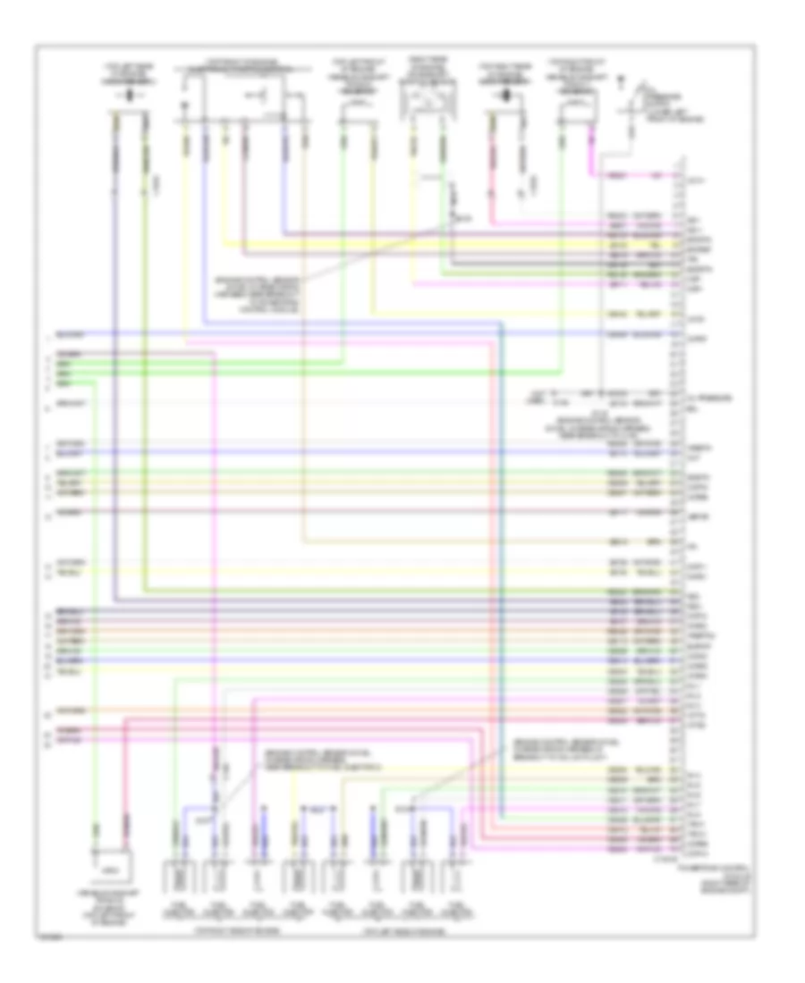
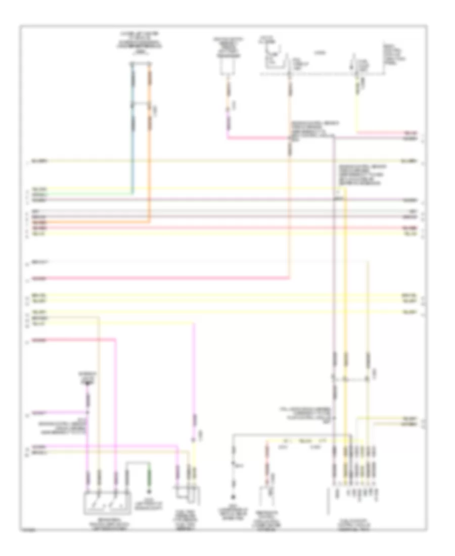
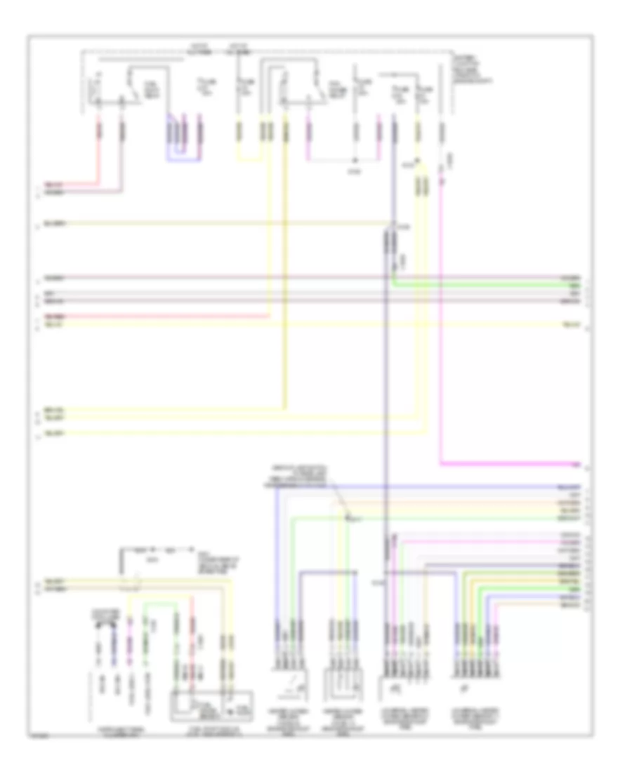
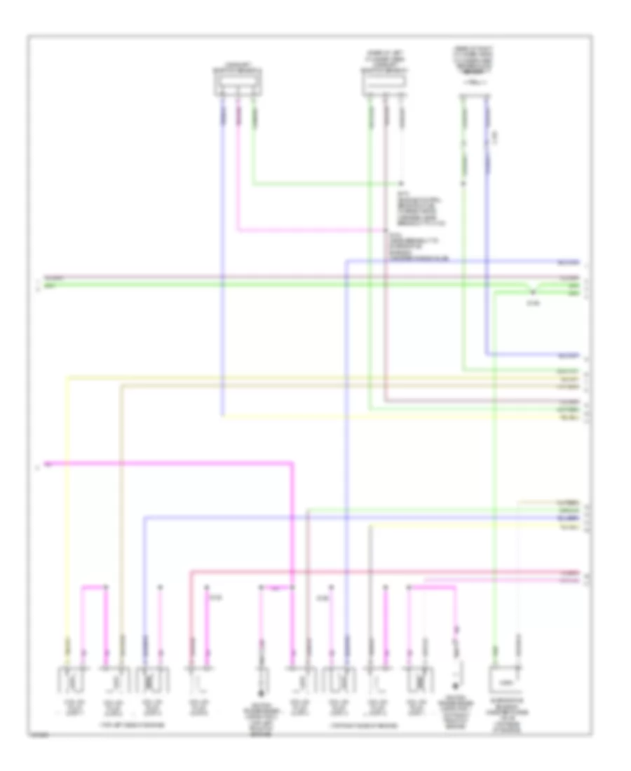
3.5L Twin Turbo, Engine Performance Wiring Diagram (4 of 6) for Ford F-150 XLT 2013
List of elements for 3.5L Twin Turbo, Engine Performance Wiring Diagram (4 of 6) for Ford F-150 XLT 2013:
- (rear of right cylinder head) cylinder head temperature (cht) sensor
- (top left side of engine)
- (top right side of engine)
- (under rear of vehicle, above spare tire) g401
- 6r80 transmission
- Battery junction box (bjb) (front of engine compt)
- C1581
- C1586
- C1587
- C210
- C310a
- Ce515
- Ce608
- Cet05
- Cet06
- Cet07
- Cet08
- Cet09
- Cet10
- Cet16
- Cet25
- Computer data lines system
- Cr167
- Ens
- Fp pwr
- Fp rtn
- Fpc
- Fpm
- Fuel injection pump (top left rear of engine)
- Fuel injector
- Fuel lvl1
- Fuel pump (fp) control module (near fuel tank)
- Fuel pump module (fuel tank assembly)
- Fuel pump relay
- Fuse 20a
- Gd117
- Gnd
- Hot at all times
- Hs can +
- Hs can -
- In breakout to fuel pump control module)
- Instrument panel cluster (ipc)
- Le111
- Lpc
- Nca
- Oss
- Re405
- Re515
- Restraints control module (rcm) (under center console)
- Ret04
- Ret24
- Ret33
- Rmc32
- Rtn
- S107 (engine control sensor wiring harness, near breakout to mass air flow/intake air temperature sensor)
- S410
- Sigrtn
- Ssa
- Ssb
- Ssc
- Ssd
- Sse
- Tcc
- Tft
- Tr gnd
- Trp
- Tspc
- Tss
- Tss/oss vpwr
- Ve225
- Ve518
- Vet27
- Vet32
- Vmc11
- Vpwr
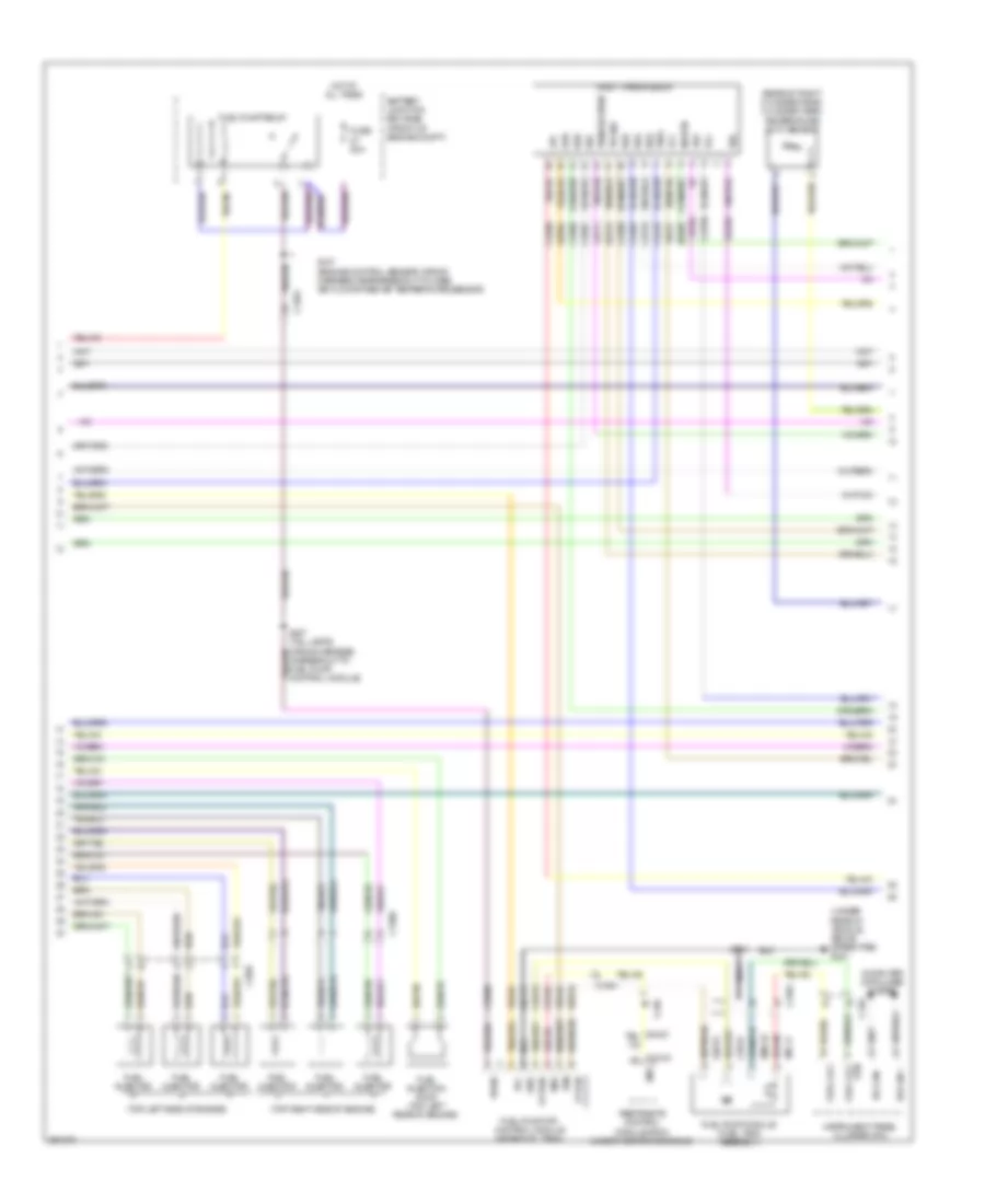
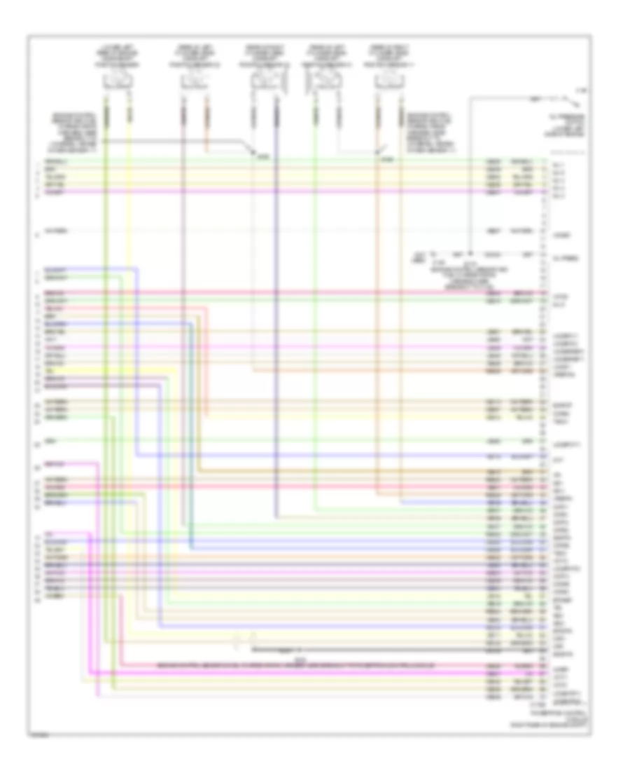
3.5L Twin Turbo, Engine Performance Wiring Diagram (5 of 6) for Ford F-150 XLT 2013
List of elements for 3.5L Twin Turbo, Engine Performance Wiring Diagram (5 of 6) for Ford F-150 XLT 2013:
- (engine control sensor & fuel charge wiring harness, near breakout to c1587) s166
- (engine control sensor & fuel charge wiring harness, near breakout to fuel rail pressure sensor)
- (engine control sensor and fuel charge wiring harness, near breakout to powertrain control module)
- (engine control sensor wiring harness, near breakout to c180)
- (left front of engine compt) electronic compressor bypass valve
- (rear of left cylinder head) camshaft position (cmp21) sensor 21
- (rear of right cylinder head) camshaft position (cmp11) sensor 11
- (top front of engine) turbo- charger (tc) wastegate regulating valve solenoid
- (top left side of engine)
- (top rear of engine) fuel rail pressure (frp) sensor
- (top rear of engine) manifold absolute pressure/intake air temperature (map/iat2) sensor 2
- (top right side of engine)
- C136
- Camshaft position 12 (cmp12) sensor (rear of right cylinder head)
- Camshaft position 22 (cmp22) sensor (rear of left cylinder head)
- Coil on plug (cop) 1
- Coil on plug (cop) 2
- Coil on plug (cop) 3
- Coil on plug (cop) 4
- Coil on plug (cop) 5
- Coil on plug (cop) 6
- Crankshaft position (ckp) sensor
- E-vref
- Electronic throttle control (top front of engine)
- G104 (rear of right cylinder head)
- G105 (left side of engine)
- Iat2
- S104
- S113
- S128
- S139
- S164
- S165
- S173
- S174
- Sigrtn
- Tmap
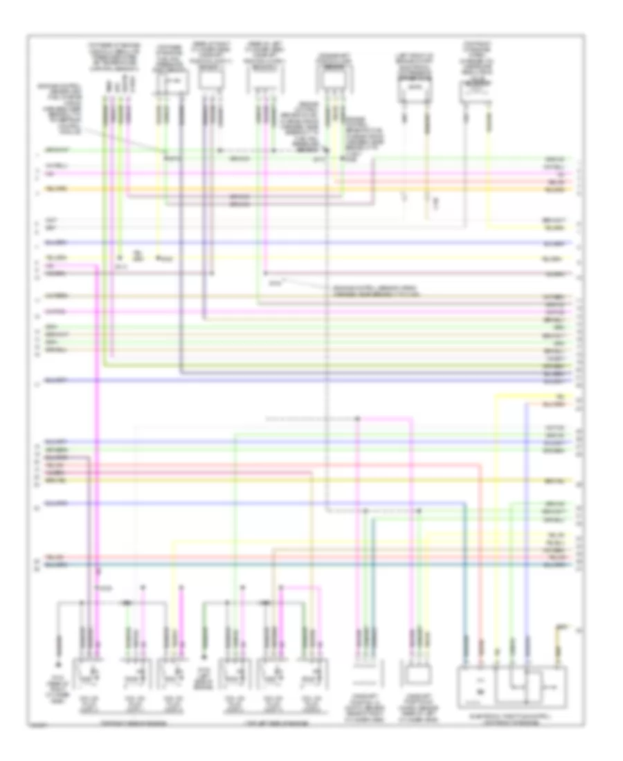
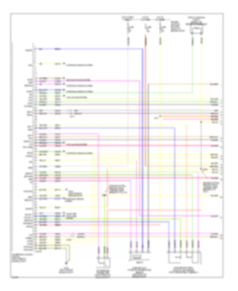
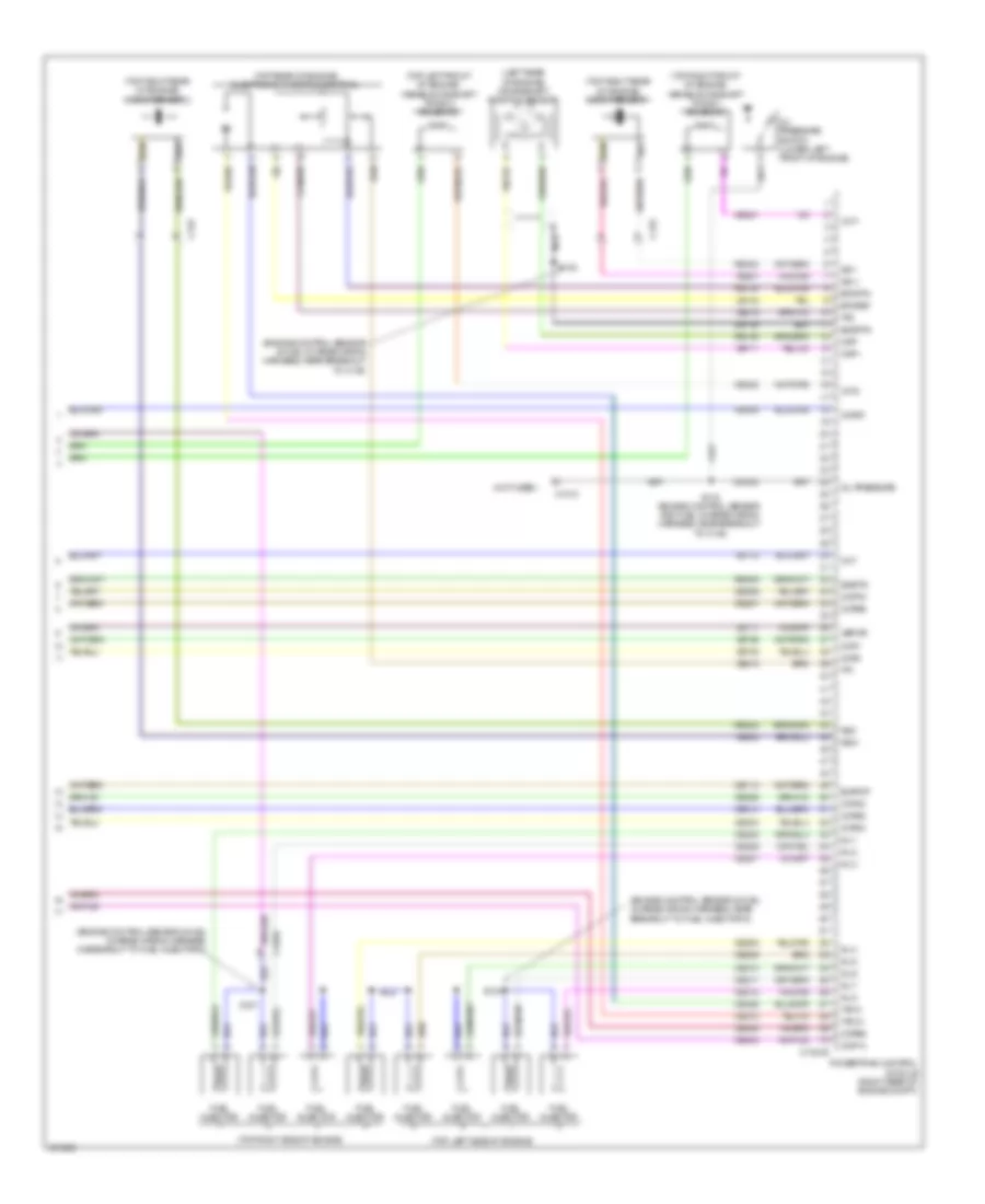
3.5L Twin Turbo, Engine Performance Wiring Diagram (6 of 6) for Ford F-150 XLT 2013
List of elements for 3.5L Twin Turbo, Engine Performance Wiring Diagram (6 of 6) for Ford F-150 XLT 2013:
- (top left side of engine) variable camshaft timing (vct21) solenoid 21
- (top left side of engine) variable camshaft timing (vct22) solenoid 22
- (top rear of engine) evaporative emission (evap) canister purge valve
- (top right front of engine) variable camshaft timing (vct11) solenoid 11
- (top right front of engine) variable camshaft timing (vct12) solenoid 12
- C146
- C1551e
- Ce235
- Ce236
- Ce303
- Ce304
- Ce306
- Ce307
- Ce421
- Ce422
- Ce442
- Ce443
- Cet05
- Cet06
- Cet08
- Cet09
- Cet10
- Cet16
- Cht
- Ckp
- Cmc24
- Cmp11
- Cmp12
- Cmp21
- Cmp22
- Cop1a
- Cop2c
- Cop4b
- Cop5d
- Cr167
- Ecbv/tcwrvs
- Etcref
- Etcrtn
- Frp
- Iat2
- Knock sensor (top rear of engine)
- Ks1 +
- Ks1 -
- Ks2 +
- Ks2 -
- Le111
- Le134
- Le143
- Le144
- Le423
- Le448
- Le449
- Le450
- Le451
- Le452
- Le453
- Lpc
- Map
- Nca
- Oil pressure switch (lower left front of engine)
- Ops
- Oss
- Powertrain control module (pcm) (right rear of engine compt)
- Re134
- Re323
- Re324
- Re405
- Re454
- Ret04
- Ret24
- Ret33
- Sigrtn
- Ssa
- Ssb
- Ssd
- Sse
- Tan
- Tcc
- Tft
- Tp 1
- Tp 2
- Tr gnd
- Trp
- Tss
- Universal heated oxygen sensor (ho2s) 11 (engine exhaust pipe)
- Universal heated oxygen sensor (ho2s) 21 (engine exhaust pipe)
- Uo2s11
- Uo2s21
- Uo2sgref11
- Uo2sgref21
- Uo2shtr11
- Uo2shtr21
- Uo2spc11
- Uo2spc21
- Uo2spct21
- Uo2ssptc11
- Vct11
- Vct12
- Vct21
- Vct22
- Ve706
- Ve707
- Ve711
- Ve712
- Ve727
- Ve740
- Ve801
- Ve802
- Ve804
- Ve818
- Ve819
- Ve824
- Ve826
- Ve827
- Vet27
- Vet32
- Vpwr
- Vref
3.7L FLEX FUEL
3.7L Flex Fuel, Engine Performance Wiring Diagram (1 of 6) for Ford F-150 XLT 2013
List of elements for 3.7L Flex Fuel, Engine Performance Wiring Diagram (1 of 6) for Ford F-150 XLT 2013:
- (engine control sensor wiring harness, near breakout to body control module) s240
- (engine control sensor wiring harness, near breakout to c144) s162
- (engine control sensor wiring harness, near breakout to g101) s169
- (under left center of vehicle) evaporative emission canister vent solenoid
- A/c pressure transducer (right front of engine compt)
- Aat
- Accr
- Acpt
- Air conditioning system
- Ambient air temperature sensor (front of engine compt)
- App1
- App2
- Apprtn
- Apprtn2
- Appvref
- Appvref2
- Battery junction box (bjb) (front of engine compt)
- Bcs2 alt
- Body control module (right kick panel)
- Bpp
- Bps
- C1581
- C175b
- C210
- C2280f
- Canv
- Cbb53
- Cbb75
- Ccb08
- Cdc10
- Cdc12
- Cdc15
- Cdc35
- Cdc54
- Ce114
- Ce436
- Ce607
- Ce608
- Cec01
- Cec02
- Ces09
- Cet42
- Cet43
- Ch302
- Computer data lines system
- Cooling fans system
- Digital
- Fpc
- Fpm
- Ftp
- Ftpref
- Fuel pump (fet)
- Fuel tank pressure (ftp) sensor (fuel tank assembly)
- Fuse 10a
- Fuse 5a
- G100 (right side of engine compt)
- Gd113
- Gencom
- Genmon
- Hfc
- Hot at all times
- Hot in run or start
- Hs can +
- Hs can -
- Iat
- Injpwrm
- Ispr
- Kapwr
- Le136
- Le137
- Le230
- Le424
- Lfc
- Maf
- Mass air flow/intake air temperature sensor (left front of engine compt)
- Micro
- Pcm wake
- Pcm wake up (fet)
- Pcmrc
- Powertrain control module (right rear of engine compt)
- Pwrgnd
- Re136
- Re137
- Re320
- Re407
- S101
- Sbb26
- Sigrtn
- Smc
- Smcs
- Sst d
- Sst u
- Start
- Starting/charging system
- Vdb04
- Vdb05
- Vdc61
- Ve225
- Ve518
- Ve701
- Ve702
- Ve740
- Ve750
- Ve807
- Ve922
- Vh433
- Vpwr
- Vref
3.7L Flex Fuel, Engine Performance Wiring Diagram (2 of 6) for Ford F-150 XLT 2013
List of elements for 3.7L Flex Fuel, Engine Performance Wiring Diagram (2 of 6) for Ford F-150 XLT 2013:
- (ignition switch assembly) passive anti-theft transceiver
- (right front corner of engine compt) generator current sensor
- (top front of engine) electronic throttle control
- (top of brake pedal assembly) accelerator pedal position (app) sensor
- 1 rtn
- Battery junction box (bjb) (front of engine compt)
- Bcs2 alt
- Brake pedal position (bpp) switch (left side of dash)
- C1581
- C192
- C210
- C211
- C214
- C310a
- Ce515
- Ce608
- Computer data lines system
- Cr167
- Ens
- Exterior lights system
- Fp pwr
- Fp rtn
- Fpc
- Fpm
- Fuel lvl
- Fuel lvl 1
- Fuel pump (fp) control module (near fuel tank)
- Fuel pump (fp) module (fuel tank assembly)
- Fuse 10a
- G102 (left front of engine compt)
- G401 (under rear of vehicle, above spare tire)
- Gd117
- Gnd
- Hot at all times
- Hs can +
- Hs can -
- Instrument panel cluster (ipc)
- Nca
- Re515
- Restraints control module (rcm) (under center console)
- Rmc32
- S112
- S407 (tail lamps wiring harness, in breakout to fuel pump control module)
- S410
- Sigrtn
- Ve225
- Ve518
- Vmc11
- Vpwr fuel
- Vref
3.7L Flex Fuel, Engine Performance Wiring Diagram (3 of 6) for Ford F-150 XLT 2013
List of elements for 3.7L Flex Fuel, Engine Performance Wiring Diagram (3 of 6) for Ford F-150 XLT 2013:
- (engine control sensor wiring harness, near breakout to mass air flow/intake air temperature sensor)
- Battery junction box (bjb) (front of engine compt)
- C140
- C146
- C175t
- C214
- Ce233
- Ce234
- Cet05
- Cet06
- Cet07
- Cet08
- Cet09
- Cet10
- Cet18
- Cet25
- Cet34
- Fuel pump relay
- Fuse 15a
- Fuse 20a
- Fuse 40a
- Ho2s12
- Ho2s22
- Hot at all times
- Htr12
- Htr22
- Le111
- Lpc
- Oss
- Pcm power relay
- Powertrain control module (right rear of engine compt)
- Re405
- Ret24
- S103
- S107
- S125
- S129
- Sigrtn
- Ssa
- Ssb
- Ssc
- Ssd
- Sse
- Tcc
- Tft
- Tows
- Tr p
- Trgnd
- Tspc
- Tss
- Ve731
- Ve733
- Vet26
- Vet27
- Vet32
- Vet33
- Vpwr
- W/ column shifter
- W/ floor shifter
3.7L Flex Fuel, Engine Performance Wiring Diagram (4 of 6) for Ford F-150 XLT 2013
List of elements for 3.7L Flex Fuel, Engine Performance Wiring Diagram (4 of 6) for Ford F-150 XLT 2013:
- (rear of right cylinder head) cylinder head temperature sensor
- (w/ column shifter)
- (w/ floor shifter) floor shifter
- 6r80 transmission
- Body control module (right kick panel)
- C1026
- C2280b
- C264
- C329
- Cet05
- Cet06
- Cet07
- Cet08
- Cet09
- Cet10
- Cet18
- Cet25
- Fuse 5a
- Heated oxygen sensor (ho2s) 12
- Heated oxygen sensor (ho2s) 22
- Hot in start or run
- Le111
- Lpc
- Nca
- Oss
- R/s
- Re405
- Ret24
- S111 (backup lamp switch to rear lamp feed wiring harness, near breakout to c140)
- S148
- Sigrtn
- Ssa
- Ssb
- Ssc
- Ssd
- Sse
- Sst d
- Sst u
- Sst-d
- Sst-u
- Tcc
- Tft
- Tow haul switch
- Tows
- Tr gnd
- Tr p
- Transmission control switch
- Tspc
- Tss
- Tss/oss vpwr
- Universal heated oxygen sensor 11 (engine exhaust pipe)
- Universal heated oxygen sensor 21 (engine exhaust pipe)
- Vet26
- Vet27
- Vet32
- Vet33
- W/ column shifter
- W/ floor shifter
3.7L Flex Fuel, Engine Performance Wiring Diagram (5 of 6) for Ford F-150 XLT 2013
List of elements for 3.7L Flex Fuel, Engine Performance Wiring Diagram (5 of 6) for Ford F-150 XLT 2013:
- (engine control sensor & fuel charge wiring harness, near breakout to camshaft position 21 sensor)
- (top left rear of engine) knock sensor
- (top left side of engine)
- (top left side of engine) variable camshaft timing solenoid 21
- (top left side of engine) variable camshaft timing solenoid 22
- (top right front of engine) variable camshaft timing solenoid 11
- (top right front of engine) variable camshaft timing solenoid 12
- (top right rear of engine) evaporative emission canister purge valve
- (top right side of engine)
- C146
- Coil on plug
- Fuel injector
- Fuel injector (top left side of engine)
- Fuel injector (top right side of engine)
- S135
- S136
- S137
- S139
- Tan
3.7L Flex Fuel, Engine Performance Wiring Diagram (6 of 6) for Ford F-150 XLT 2013
List of elements for 3.7L Flex Fuel, Engine Performance Wiring Diagram (6 of 6) for Ford F-150 XLT 2013:
- (engine control sensor & fuel charge wiring harness, near breakout to powertrain control module)
- (engine control sensor and fuel charge wiring harness, near breakout to universal heated oxygen sensor 11)
- (lower left rear of engine) crankshaft position sensor
- (not used)
- (rear of left cylinder head) camshaft position sensor 21
- (rear of left cylinder head) camshaft position sensor 22
- (rear of right cylinder head) camshaft position sensor 11
- (rear of right cylinder head) camshaft position sensor 12
- C146
- C175e
- Ce113
- Ce205
- Ce206
- Ce207
- Ce208
- Ce209
- Ce210
- Ce235
- Ce236
- Ce303
- Ce304
- Ce305
- Ce306
- Ce307
- Ce308
- Ce412
- Ce421
- Ce422
- Ce426
- Ce442
- Ce443
- Cht
- Ckp+
- Ckp-
- Cmc24
- Cmp11
- Cmp12
- Cmp21
- Cmp22
- Cop1a
- Cop2c
- Cop3e
- Cop4b
- Cop5d
- Cop6f
- De135
- Etcref
- Etcrtn
- Evapcp
- Inj 1
- Inj 2
- Inj 3
- Inj 4
- Inj 5
- Inj 6
- Ks1+
- Ks1-
- Ks2+
- Ks2-
- Le134
- Le448
- Le449
- Le450
- Le451
- Le452
- Le453
- Nca
- Oil press
- Oil pressure switch (lower left side of engine)
- Powertrain control module (right rear of engine compt)
- Re134
- Re135
- Re323
- Re324
- Re405
- Re429
- S116 (engine control sensor and fuel charge wiring harness, near breakout to c146)
- S138
- S159
- S160
- Shdrtn
- Sigrtn
- Tacm+
- Tacm-
- Tp1
- Tp2
- Uo2s11
- Uo2s21
- Uo2sgref11
- Uo2sgref21
- Uo2shtr11
- Uo2shtr21
- Uo2spc11
- Uo2spc21
- Uo2spct11
- Uo2spct21
- Vct11
- Vct12
- Vct21
- Vct22
- Ve706
- Ve707
- Ve711
- Ve712
- Ve801
- Ve802
- Ve818
- Ve819
- Ve826
- Ve827
- Vrsrtn
- Vrsrtn2
5.0L FLEX FUEL
5.0L Flex Fuel, Engine Performance Wiring Diagram (1 of 6) for Ford F-150 XLT 2013
List of elements for 5.0L Flex Fuel, Engine Performance Wiring Diagram (1 of 6) for Ford F-150 XLT 2013:
- (engine control sensor wiring harness, near breakout to c144)
- (engine control sensor wiring harness, near breakout to g101)
- (front of engine compt) ambient air temperature sensor
- A/c pressure transducer (right front of engine compt)
- Aat
- Accelerator pedal position (app) sensor (top of brake pedal assembly)
- Accr
- Acpt
- Air conditioning system
- App 1
- App vrfe
- App2
- Apprtn
- Apprtn2
- Appvref2
- Battery junction box (bjb) (front of engine compt)
- Bcs2 alt
- Bpp
- Bps
- C1381b
- C1581
- C210
- Canv
- Cbb53
- Cbb75
- Ccb08
- Cdc10
- Cdc12
- Cdc15
- Cdc35
- Cdc54
- Ce114
- Ce436
- Ce607
- Ce608
- Cec01
- Cec02
- Ces09
- Cet42
- Cet43
- Ch302
- Computer data lines system
- Cooling fans system
- Digital
- Fpc
- Fpm
- Ftp
- Ftpref
- Fuse 10a
- Fuse 5a
- G100 (right side of engine compt)
- Gd113
- Gencom
- Genmon
- Hfc
- Hot at all times
- Hot in start or run
- Hs can +
- Hs can -
- Iat
- Injpwrm
- Ispr
- Kapwr
- Le136
- Le137
- Le230
- Le424
- Lfc
- Maf
- Mass air flow/ intake air temperature sensor (left front of engine compt)
- Pcm wake
- Pcmrc
- Powertrain control module (right rear of engine compt)
- Pwr gnd
- Re136
- Re137
- Re320
- Re407
- S101
- S162
- S169
- Sbb26
- Sigrtn
- Smc
- Smcs
- Sst-d
- Sst-u
- Start
- Starting/charging system
- Vdb04
- Vdb05
- Vdc61
- Ve225
- Ve518
- Ve701
- Ve702
- Ve740
- Ve750
- Ve807
- Ve922
- Vh433
- Vpwr
- Vref
- Vref 5v
5.0L Flex Fuel, Engine Performance Wiring Diagram (2 of 6) for Ford F-150 XLT 2013
List of elements for 5.0L Flex Fuel, Engine Performance Wiring Diagram (2 of 6) for Ford F-150 XLT 2013:
- (engine control sensor wiring harness, near breakout to body control module) s240
- (engine control sensor wiring harness, near breakout to mass air flow/intake air temperature sensor)
- (ignition switch assembly) passive anti-theft transceiver
- (right front corner of engine compt) generator current sensor
- (tail lamps wiring harness, in breakout to fuel pump control module) s407
- (under left center of vehicle) evaporative emission canister vent solenoid
- Bcs2 alt
- Body control module (right kick panel)
- Brake pedal position (bpp) switch (left side of dash)
- C1581
- C192
- C210
- C214
- C2280f
- C310a
- Ce515
- Ce608
- Cr167
- Ens
- Exterior lights system
- Fp pwr
- Fp rtn
- Fpc
- Fpm
- Fuel pump (fet)
- Fuel pump (fp) control module (near fuel tank)
- Fuel tank pressure (ftp) sensor (fuel tank assembly)
- Fuse 10a
- G102 (left front of engine compt)
- G401 (under rear of vehicle, above spare tire)
- Gd117
- Gnd
- Hot at all times
- Micro
- Pcm wake up (fet)
- Re515
- Restraints control module (rcm) (under center console)
- S107
- S112
- S410
- Sigrtn
- Ve225
- Ve518
- Vpwr
- Vref
5.0L Flex Fuel, Engine Performance Wiring Diagram (3 of 6) for Ford F-150 XLT 2013
List of elements for 5.0L Flex Fuel, Engine Performance Wiring Diagram (3 of 6) for Ford F-150 XLT 2013:
- (backup lamp switch to rear lamp feed wiring harness, near breakout to c140)
- Battery junction box (bjb) (front of engine compt)
- C140
- C146
- C1581
- C210
- Ce515
- Computer data lines system
- Fuel gauge sensor
- Fuel level 1
- Fuel pump
- Fuel pump (fp) module (fuel tank assembly)
- Fuel pump relay
- Fuse 15a
- Fuse 20a
- Fuse 40a
- G401 (under rear of vehicle, above spare tire)
- Heated oxygen sensor (ho2s) 12 (engine exhaust pipe)
- Heated oxygen sensor (ho2s) 22 (engine exhaust pipe)
- Hot at all times
- Hs can +
- Hs can -
- Instrument panel cluster (ipc)
- Nca
- Pcm power relay
- Re515
- Rmc32
- Rtn fuel level 1
- S103
- S111
- S125
- S129
- S148
- S410
- Universal heated oxygen sensor 11 (engine exhaust pipe)
- Universal heated oxygen sensor 21 (engine exhaust pipe)
- Vmc11
5.0L Flex Fuel, Engine Performance Wiring Diagram (4 of 6) for Ford F-150 XLT 2013
List of elements for 5.0L Flex Fuel, Engine Performance Wiring Diagram (4 of 6) for Ford F-150 XLT 2013:
- (w/ column shifter) tow haul switch
- 6r80 transmission
- Body control module (right kick panel)
- C1381t
- C140
- C211
- C214
- C2280b
- C264
- C329
- Ce233
- Ce234
- Ce235
- Ce236
- Cet05
- Cet06
- Cet07
- Cet08
- Cet09
- Cet10
- Cet18
- Cet25
- Cet34
- Floor shifter (w/ floor shifter)
- Fuse 5a
- Ho2s12
- Ho2s22
- Hot in start or run
- Htr12
- Htr22
- Le111
- Le448
- Le449
- Le450
- Le451
- Le452
- Le453
- Lpc
- Nca
- Oss
- Powertrain control module (right rear of engine compt)
- R/s
- Re405
- Re406
- Ret24
- Sigrtn
- Ssa
- Ssb
- Ssc
- Ssd
- Sse
- Sst-d
- Sst-u
- Tcc
- Tft
- Tows
- Tr gnd
- Tr p
- Tr-p
- Transmission control switch
- Tspc
- Tss
- Tss/oss vpwr
- Uo2s11
- Uo2s21
- Uo2sgref11
- Uo2sgref21
- Uo2shtr11
- Uo2shtr21
- Uo2spc11
- Uo2spc21
- Uo2spct11
- Ve731
- Ve733
- Ve826
- Ve827
- Vet26
- Vet27
- Vet32
- Vet33
- Vpwr
- W/ column shifter
- W/ floor shifter
5.0L Flex Fuel, Engine Performance Wiring Diagram (5 of 6) for Ford F-150 XLT 2013
List of elements for 5.0L Flex Fuel, Engine Performance Wiring Diagram (5 of 6) for Ford F-150 XLT 2013:
- (engine control sensor & fuel charge wiring harness, near breakout to c1019)
- (engine control sensor wiring harness, near breakout to fuel injector 3)
- (left side of oil pan) low oil level switch
- (rear of left cylinder head) camshaft position sensor 21
- (rear of left cylinder head) camshaft position sensor 22
- (rear of right cylinder head) camshaft position sensor 11
- (rear of right cylinder head) camshaft position sensor 12
- (rear of right cylinder head) cylinder head temperature sensor
- (top left side of engine)
- (top right side of engine)
- Coil on plug (cop) 1
- Coil on plug (cop) 2
- Coil on plug (cop) 3
- Coil on plug (cop) 4
- Coil on plug (cop) 5
- Coil on plug (cop) 6
- Coil on plug (cop) 7
- Coil on plug (cop) 8
- Evaporative emission canister purge valve (top front of engine)
- Ignition transformer capacitor 1 (top right rear of engine)
- S104
- S135
- S136
- S139
- S173
- Variable camshaft timing 12 solenoid (top right front of engine)
5.0L Flex Fuel, Engine Performance Wiring Diagram (6 of 6) for Ford F-150 XLT 2013
List of elements for 5.0L Flex Fuel, Engine Performance Wiring Diagram (6 of 6) for Ford F-150 XLT 2013:
- (engine control sensor & fuel charge wiring harness, in breakout to coil on plug 7)
- (engine control sensor & fuel charge wiring harness, near breakout to fuel injector 2)
- (engine control sensor & fuel charge wiring harness, near breakout to powertrain control module)
- (not used) c146
- (right rear of engine) crankshaft position sensor
- (top front of engine) electronic throttle control
- (top left front of engine) variable camshaft timing 21 solenoid
- (top left rear of engine) knock sensor 2
- (top left side of engine)
- (top right front of engine) variable camshaft timing 11 solenoid
- (top right rear of engine) knock sensor 1
- (top right side of engine)
- C1019
- C1381e
- C146
- Ce113
- Ce205
- Ce206
- Ce207
- Ce208
- Ce209
- Ce210
- Ce211
- Ce212
- Ce303
- Ce304
- Ce305
- Ce306
- Ce307
- Ce308
- Ce309
- Ce310
- Ce412
- Ce421
- Ce422
- Ce426
- Ce442
- Ce443
- Cht
- Ckp+
- Ckp-
- Cmc24
- Cmp11
- Cmp12
- Cmp21
- Cmp22
- Cop1a
- Cop2h
- Cop3f
- Cop4c
- Cop5b
- Cop6e
- Cop7g
- Cop8d
- De135
- Eol
- Etcref
- Etcrtn
- Evapcp
- Fuel injector
- Inj 1
- Inj 2
- Inj 3
- Inj 4
- Inj 5
- Inj 6
- Inj 7
- Inj 8
- Ks1+
- Ks1-
- Ks2+
- Ks2-
- Le111
- Le134
- Le142
- Nca
- Oil pressure
- Oil pressure switch (lower left front of engine)
- Powertrain control module (right rear of engine compt)
- Re134
- Re135
- Re323
- Re324
- Re405
- Re429
- S116 (engine control sensor & fuel charge wiring harness, near breakout to c146)
- S134
- S137
- S138
- Shdrtn
- Sigrtn
- Tacm+
- Tacm-
- Tp1
- Tp2
- Variable camshaft timing 22 solenoid (top left front of engine)
- Vbpwr
- Vct11
- Vct12
- Vct21
- Vct22
- Ve706
- Ve707
- Ve711
- Ve712
- Ve736
- Ve738
- Ve801
- Ve802
- Ve818
- Ve819
- Vrsrtn
- Vrsrtn2
6.2L
6.2L, Engine Performance Wiring Diagram (1 of 6) for Ford F-150 XLT 2013
List of elements for 6.2L, Engine Performance Wiring Diagram (1 of 6) for Ford F-150 XLT 2013:
- (engine control sensor wiring harness, near breakout to c144)
- (engine control sensor wiring harness, near near breakout to g101)
- (front of engine compt) ambient air temperature sensor
- A/c pressure transducer (right front of engine compt)
- Aat
- Accelerator pedal position (app) sensor (top of brake pedal assembly)
- Accr
- Acpt
- Air conditioning system
- App1
- App2
- Apprtn
- Apprtn2
- Appvref
- Appvref2
- Battery junction box (bjb) (front of engine compt)
- Bpp
- Bps
- C1381b
- C1581
- C210
- Canv
- Cbb53
- Cbb75
- Ccb08
- Cdc10
- Cdc12
- Cdc15
- Cdc35
- Cdc54
- Ce114
- Ce436
- Ce607
- Ce608
- Cec01
- Cec02
- Ces09
- Cet42
- Cet43
- Ch302
- Computer data lines system
- Cooling fans system
- Digital
- Fpc
- Fpm
- Ftp
- Ftpref
- Fuse 10a
- Fuse 5a
- G100 (right side of engine compt)
- Gd113
- Gencom
- Genmon
- Hfc
- Hot at all times
- Hot in start or run
- Hs can +
- Hs can -
- Iat
- Injpwrm
- Ispr
- Kapwr
- Le136
- Le137
- Le230
- Le424
- Lfc
- Maf
- Mass air flow/ intake air temperature sensor (left front of engine compt)
- Pcm wake
- Pcmrc
- Powertrain control module (right rear of engine compt)
- Pwr gnd
- Re136
- Re137
- Re320
- Re407
- S101
- S162
- S169
- Sbb26
- Sigrtn
- Smc
- Smcs
- Sst-d
- Sst-u
- Start
- Starting/charging system
- Vdb04
- Vdb05
- Ve225
- Ve518
- Ve701
- Ve702
- Ve740
- Ve750
- Ve807
- Ve922
- Vh433
- Vpwr
- Vref
- Vref 5v
6.2L, Engine Performance Wiring Diagram (2 of 6) for Ford F-150 XLT 2013
List of elements for 6.2L, Engine Performance Wiring Diagram (2 of 6) for Ford F-150 XLT 2013:
- (engine control sensor wiring harness, near breakout to body control module) s240
- (engine control sensor wiring harness, near breakout to mass air flow/intake air temperature sensor)
- (ignition switch assembly) passive anti-theft transceiver
- (tail lamps wiring harness, in breakout to fuel pump control module) s407
- (under left center of vehicle) evaporative emission canister vent solenoid
- Body control module (right kick panel)
- Brake pedal position (bpp) switch (left side of dash)
- C1581
- C210
- C214
- C2280f
- C310a
- Ce515
- Ce608
- Cr167
- Ens
- Exterior lights system
- Fp pwr
- Fp rtn
- Fpc
- Fpm
- Fuel pump (fet)
- Fuel pump (fp) control module (near fuel tank)
- Fuel tank pressure (ftp) sensor (fuel tank assembly)
- Fuse 10a
- G102 (left front of engine compt)
- G401 (under rear of vehicle, above spare tire)
- Gd117
- Gnd
- Hot at all times
- Micro
- Pcm wake up (fet)
- Re515
- Restraints control module (rcm) (under center console)
- S107
- S112 (engine control sensor wiring harness, near breakout to c110)
- S410
- Ve225
- Ve518
- Vpwr
6.2L, Engine Performance Wiring Diagram (3 of 6) for Ford F-150 XLT 2013
List of elements for 6.2L, Engine Performance Wiring Diagram (3 of 6) for Ford F-150 XLT 2013:
- (backup lamp switch to rear lamp feed wiring harness, near breakout to c140)
- Battery junction box (bjb) (front of engine compt)
- C1010
- C140
- C1581
- C210
- Ce515
- Computer data lines system
- Fuel gauge sensor
- Fuel level 1
- Fuel level1 rtn
- Fuel pump
- Fuel pump module (fuel tank assembly)
- Fuel pump relay
- Fuse 15a
- Fuse 20a
- Fuse 40a
- G401 (under rear of vehicle, above spare tire)
- Heated oxygen sensor (ho2s) 12 (engine exhaust pipe)
- Heated oxygen sensor (ho2s) 22 (engine exhaust pipe)
- Hot at all times
- Hs can +
- Hs can -
- Instrument panel cluster (ipc)
- Nca
- Pcm power relay
- Re515
- Rmc32
- S103
- S111
- S125
- S129
- S148
- S410
- Universal heated oxygen sensor 11 (engine exhaust pipe)
- Universal heated oxygen sensor 21 (engine exhaust pipe)
- Vmc11
6.2L, Engine Performance Wiring Diagram (4 of 6) for Ford F-150 XLT 2013
List of elements for 6.2L, Engine Performance Wiring Diagram (4 of 6) for Ford F-150 XLT 2013:
- (w/ column shifter) tow haul switch
- 6r80 transmission
- Body control module (right kick panel)
- C1381t
- C140
- C211
- C214
- C2280b
- C264
- C329
- Ce233
- Ce234
- Ce235
- Ce236
- Cet05
- Cet06
- Cet07
- Cet08
- Cet09
- Cet10
- Cet18
- Cet25
- Cet34
- Floor shifter (w/ floor shifter)
- Fuse 5a
- Ho2s12
- Ho2s22
- Hot in start or run
- Htr12
- Htr22
- Le111
- Le448
- Le449
- Le450
- Le451
- Le452
- Le453
- Lpc
- Nca
- Oss
- Powertrain control module (right rear of engine compt)
- R/s
- Re405
- Re406
- Ret24
- Sigrtn
- Ssa
- Ssb
- Ssc
- Ssd
- Sse
- Sst-d
- Sst-u
- Tcc
- Tft
- Tows
- Tr gnd
- Tr p
- Tr-p
- Transmission control switch
- Tspc
- Tss
- Tss/oss vpwr
- Uo2s11
- Uo2s21
- Uo2sgref11
- Uo2sgref21
- Uo2shtr11
- Uo2shtr21
- Uo2spc11
- Uo2spc21
- Uo2spct11
- Ve731
- Ve733
- Ve826
- Ve827
- Vet26
- Vet27
- Vet32
- Vet33
- Vpwr
- W/ column shifter
- W/ floor shifter
6.2L, Engine Performance Wiring Diagram (5 of 6) for Ford F-150 XLT 2013
List of elements for 6.2L, Engine Performance Wiring Diagram (5 of 6) for Ford F-150 XLT 2013:
- (rear of left cylinder head) camshaft position sensor 1
- (rear of right cylinder head) cylinder head temperature sensor
- (top left side of engine)
- (top right side of engine)
- C133
- Camshaft position sensor 2
- Coil on plug (cop) 1
- Coil on plug (cop) 2
- Coil on plug (cop) 3
- Coil on plug (cop) 4
- Coil on plug (cop) 5
- Coil on plug (cop) 6
- Coil on plug (cop) 7
- Coil on plug (cop) 8
- Evaporative emission canister purge valve (top rear of engine)
- Ignition transformer capacitor 1 (top right front of engine)
- Ignition transformer capacitor 2 (top left front of engine)
- S104 (near breakout to evaporative emission canister purge valve)
- S135
- S136
- S139
- S173 (engine control sensor & fuel charge wiring harness, near breakout to c133)
6.2L, Engine Performance Wiring Diagram (6 of 6) for Ford F-150 XLT 2013
List of elements for 6.2L, Engine Performance Wiring Diagram (6 of 6) for Ford F-150 XLT 2013:
- (engine control sensor & fuel charge wiring harness, in breakout to fuel injector 3)
- (engine control sensor & fuel charge wiring harness, near breakout to c146)
- (engine control sensor & fuel charge wiring harness, near breakout to fuel injector 6)
- (left rear of engine) crankshaft position sensor
- (not used)
- (top left front of engine) variable camshaft timing 2 solenoid
- (top left side of engine)
- (top rear of engine) electronic throttle control
- (top right front of engine) variable camshaft timing 1 solenoid
- (top right rear of engine) knock sensor 1
- (top right rear of engine) knock sensor 2
- (top right side of engine)
- C1010
- C133
- C1381e
- Ce113
- Ce205
- Ce206
- Ce207
- Ce208
- Ce209
- Ce210
- Ce211
- Ce212
- Ce303
- Ce304
- Ce305
- Ce306
- Ce307
- Ce308
- Ce309
- Ce310
- Ce412
- Ce421
- Ce422
- Ce426
- Cht
- Ckp+
- Ckp-
- Cmc24
- Cmp1
- Cmp2
- Cop1a
- Cop2h
- Cop3f
- Cop4c
- Cop5b
- Cop6e
- Cop7g
- Cop8d
- De135
- Etcref
- Etcrtn
- Evapcp
- Fuel injector
- Inj 1
- Inj 2
- Inj 3
- Inj 4
- Inj 5
- Inj 6
- Inj 7
- Inj 8
- Ks1+
- Ks1-
- Ks2+
- Ks2-
- Le111
- Le134
- Nca
- Oil pressure
- Oil pressure switch (lower left front of engine)
- Powertrain control module (right rear of engine compt)
- Re134
- Re135
- Re323
- Re324
- Re405
- S116 (engine control sensor and fuel charge wiring harness, near breakout to c146)
- S134
- S137
- S138
- Shdrtn
- Sigrtn
- Tacm+
- Tacm-
- Tp1
- Tp2
- Vbpwr
- Vct1
- Vct2
- Ve711
- Ve712
- Ve736
- Ve738
- Ve801
- Ve802
- Ve818
- Ve819

 Čeština
 Dansk
Dansk Deutsch
 Ελληνικά
 English
 English
 Español
 Suomi
Suomi Français
 Français
 עברית
עברית Hrvatski
 Magyar
 Italiano
 日本語
日本語 한국어
한국어 Nederlands
 Polski
 Português
 Română
 Русский
 Slovenčina
 Slovenščina
 Svenska
 Türkçe
 中文 (中国)