POWER DISTRIBUTION
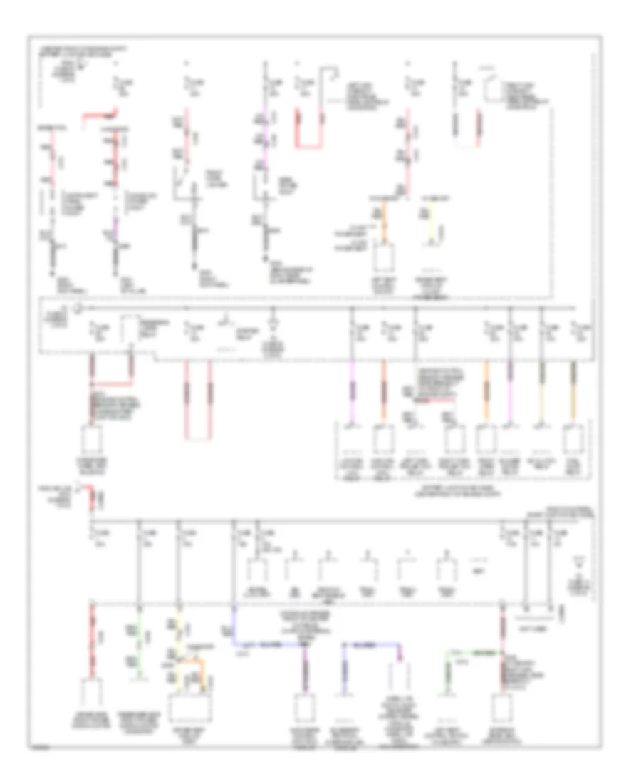
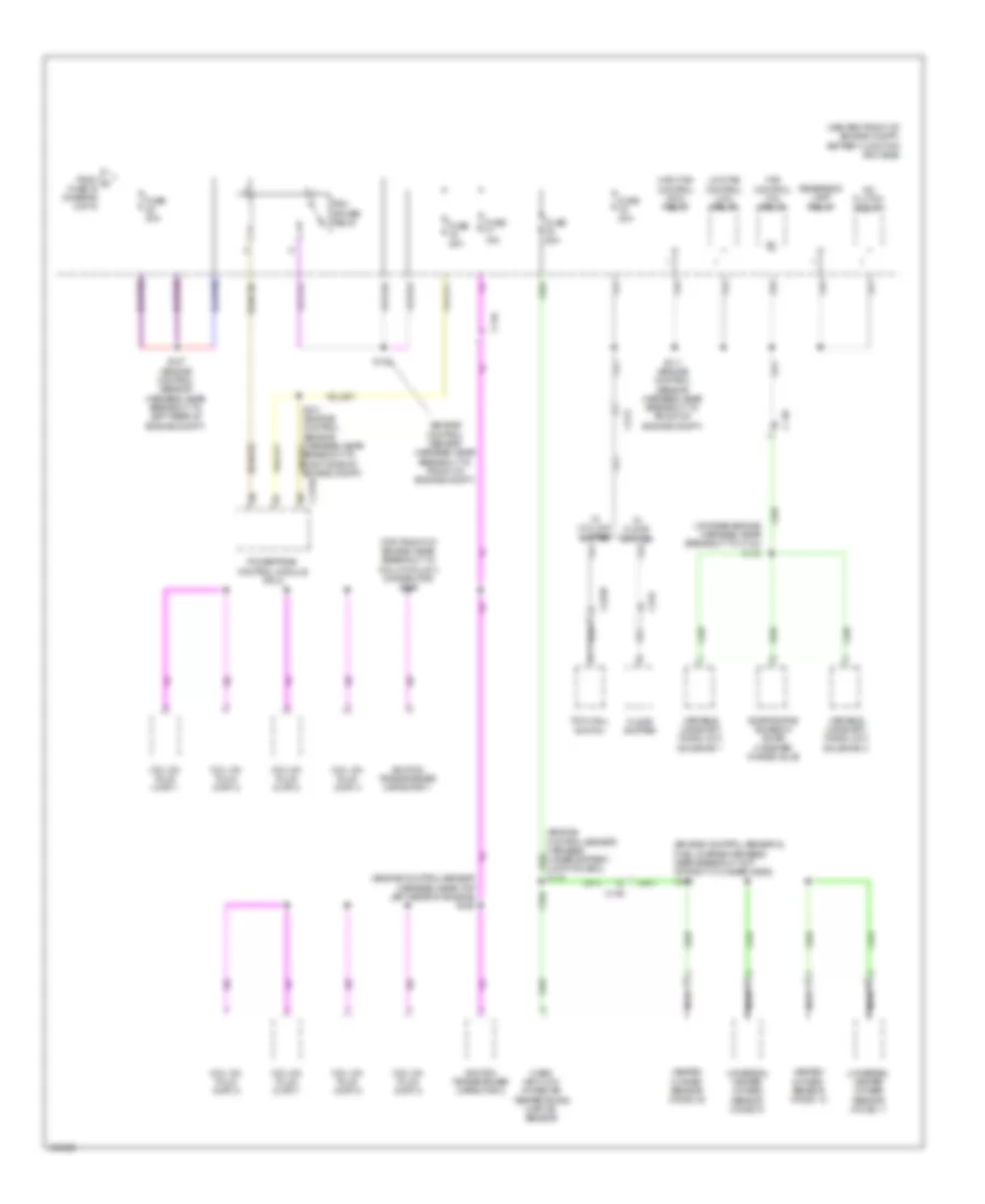
Power Distribution Wiring Diagram (1 of 6) for Ford Expedition Limited 2014
 https://portal-diagnostov.com/license.html
Automotive Electricians Portal FZCO
Automotive Electricians Portal FZCO
https://portal-diagnostov.com/license.html
https://portal-diagnostov.com/license.html
Automotive Electricians Portal FZCO
Automotive Electricians Portal FZCO
List of elements for Power Distribution Wiring Diagram (1 of 6) for Ford Expedition Limited 2014:
- (center front of engine compt) battery junction box (bjb)
- (expedition: engine control sensor harness, under battery junction box) (navigation: engine control sensor harness, near breakout for right headlight) s114
- (in engine harness, near right side of battery junction box (bjb))
- (in engine harness, near right side of battery junction box (bjb)) s148
- 10-way power seat
- 6-way power seat
- Air suspension compressor relay
- Anti-lock brake system (abs) module
- Auxiliary blower motor relay 1
- Auxiliary relay box 2 (behind rear of right rear quarterpanel)
- Battery
- Battery charge trailer tow relay
- Brake pedal position (bpp) switch
- C139
- C175b
- C210
- C211
- C212
- C2131a
- C314
- C316
- C3265a f
- C3313b
- C410
- C4174a
- C465
- C922
- Console 1 power point
- Dual climate controlled seat module (dcsm)
- Evaporative emissions (evap) canister vent solenoid
- From splice s212 (diagram 4 of 6)
- Fuse 10a
- Fuse 20a
- Fuse 25a
- Fuse 30a
- Fuse 40a
- Fuse 5a
- Fuse 60a
- Fusible link d (10 ga- red)
- G100 (right side of engine compt)
- G101 (right side of engine compt)
- G102 (right rear of engine)
- G107 (right rear of engine compt)
- Generator
- Left rear corner of engine compt)
- Parking lamp trailer tow relay
- Power liftgate/ trunk module
- Power running board (prb) module
- Powertrain control module (pcm)
- Rear window defrost relay
- Red
- Right seat control switch
- Roof opening panel module
- Run/ start relay
- S102
- S104 red (engine control sensor harness, near breakout to c140)
- S105 (engine control sensor harness, near breakout red to c140)
- S149
- S159 (in harness, near right side of battery junction box (bjb))
- S3005
- S369
- Starter motor
- Third row power-fold seat relay
- To battery junction box (bjb) (diagram 5 of 6)
- To fuse 52 (diagram 5 of 6)
- To fuse 65 (diagram 2 of 6)
- To smart junction box (sjb) (diagram 2 of 6)
- Trailer brake control module (tbc)
- Vehicle dynamics module (vdm)
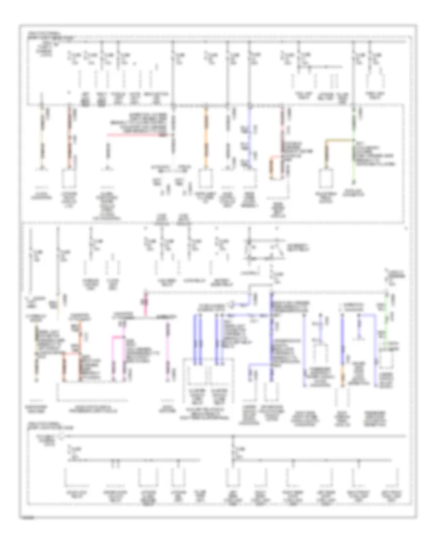
Power Distribution Wiring Diagram (2 of 6) for Ford Expedition Limited 2014
List of elements for Power Distribution Wiring Diagram (2 of 6) for Ford Expedition Limited 2014:
- (center front of engine compt)
- (center front of engine compt) battery junction box (bjb)
- (console harness, front of center console) (w/ apim & external
- (not used)
- (right kick panel) smart junction box (sjb)
- 10-way power seat
- 3rd row seat enable (fet)
- 6-way power seat
- A/c clutch relay
- Accessory protocol interface (aim) module
- Audio rear control unit (rcu) module
- Battery junction box (bjb)
- Blower motor relay
- Bsi (fet)
- C210
- C211
- C212
- C213
- C2280d
- C2280g
- C311
- C312
- C314
- C341a
- C341b
- C341c
- C410
- C510
- C610
- Console 2 power point
- Driver seat module (10-way power seat)
- Driver seat module (dsm)
- Driver side front power window motor
- Expedition
- Exterior rear view mirror switch
- From fuse 43 (diagram 1 of 6)
- From splice a s104 (diagram 1 of 6)
- Front cigar lighter
- Front wiper relay
- Fuel pump relay
- Fuse 10a
- Fuse 10a (or 15a)
- Fuse 15a
- Fuse 20a
- Fuse 25a
- Fuse 30a
- Fuse 40a
- Fuse 5a
- Fuse 7.5a
- G200 (right kick panel)
- G301 (left "b" pillar)
- G402 (behind rear of right rear quarterpanel)
- High fan control (hfc) relay
- Instrument panel power point
- Integrated wheel end solenoid
- Keypad illum (fet)
- Left high intensity discharge headlamp relay (navigator)
- Left seat control switch
- Left seat control switch (w/ memory)
- Left turn trailer tow relay
- Low fan control (lfc) relay
- Navigator
- Passenger side front power window motor (navigator)
- Rear power point
- Red
- Reversing lamps relay
- Right high intensity discharge headlamp relay (navigator)
- Right turn trailer tow relay
- S121 (engine control sensor harness, under battery junction box)
- S359
- S369
- Satellite digital audio receiver system (sdars) module (navigator satellite radio w/o navigation)
- Sdars) s382
- Starter relay
- To fuse 14 (diagram 3 of 6)
- To fuse 33 (diagram 4 of 6)
- To fuse 35 (diagram 6 of 6)
- Tpms 1 (fet)
- Tpms 2 (fet)
- Tpms 3 (fet)
- Vbat
- W/ memory
- W/o memory
Power Distribution Wiring Diagram (3 of 6) for Ford Expedition Limited 2014
List of elements for Power Distribution Wiring Diagram (3 of 6) for Ford Expedition Limited 2014:
- (expedition: on rear dash harness, near breakout to climate control) (navigator: main harness, near breakout to c238) s266
- (right kick panel) smart junction box (sjb)
- 25a
- Accessory delay relay
- Adjustable pedal switch
- Audio amplifier
- Audio control module (acm)
- Audio digital signal processing (dsp) module
- Automatic a/c
- Auxiliary relay box 2 (behind rear of right rear quarterpanel)
- Backlighting led (fet)
- Battery saver relay
- C214
- C2280a
- C2280a (not used)
- C2280b
- C2280d
- C228a
- C2357a
- C2364a
- C2385b
- C240a
- C3054b
- C314
- C410
- C411
- C4174a
- C465
- C504a
- C510
- C535a
- C535b
- C610
- C922
- C935
- Circuit breaker 30a
- Clock (navigator)
- Control
- Data link connector
- Door lock relay
- Driver door unlock relay
- Driver side door lock switch (expedition)
- Driver side front power window motor
- Expedition
- Floor lamp (fet)
- Fog lamp relay
- From g fuse 13 (diagram 2 of 6)
- Fuse
- Fuse 10a
- Fuse 15a
- Fuse 20a
- Global positioning system
- High beam relay
- Horn relay
- Hvac (datc) module
- Hvac (emtc) module
- Instrument cluster (ic)
- Interior lighting (fet)
- Left front turn lamp (fet)
- Left low beam (fet)
- Left rear stop/ turn lamp (fet)
- Left rear turn lamp (fet)
- Liftgate glass release relay
- Liftgate rel (fet)
- Liftgate/ trunk module (ltm)
- Manual a/c
- Master window adjust switch
- Master window adjust switch (navigator)
- Module (gpsm) (w/ sync w/o navigation)
- Navigator
- Navigator w/ thx audio
- Near breakout to passenger's door) s601
- Park lamp relay
- Passenger side door lock switch (expedition)
- Passenger side front power window motor (navigator)
- Puddle lamp (fet)
- Pulse train (fet)
- Quarter window close relay
- Quarter window open relay
- Rear heated seat module
- Rear wiper motor assembly
- Right front turn lamp (fet)
- Right low beam (fet)
- Right rear stop/ turn lamp (fet)
- Right rear turn lamp (fet)
- Right side front power window switch (navigator)
- Roof opening panel module
- S209 (body main harness, near breakout to below right side of dash)
- S217 (w/o memory) (on rear dash harness, near breakout to instrument cluster)
- S236 (body main harness, near breakout to c2364c)
- Subwoofer amplifier
- To fuse 27 (diagram 4 of 6)
- To splice s208 (diagram 4 of 6)
- W/ premium sound
- White light (fet)
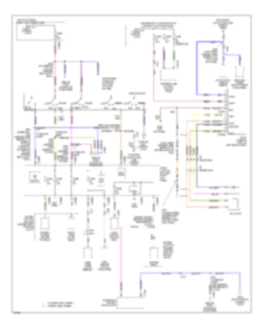
Power Distribution Wiring Diagram (4 of 6) for Ford Expedition Limited 2014
List of elements for Power Distribution Wiring Diagram (4 of 6) for Ford Expedition Limited 2014:
- (body main harness, near breakout to g203) s212
- (center front of engine compt) battery junction box (bjb)
- (engine control sensor harness, near breakout to pcm) s107
- (expedition) c315
- (main wiring nca
- (navigator) c315
- (not used)
- (right kick panel) smart junction box (sjb)
- A/c outlet
- Acc
- Ac_a
- Ac_b
- Audio control module (acm)
- Auto-dimming interior mirror
- Battery charge trailer tow relay
- Battery junction box (bjb) (center front of engine compt)
- C175b
- C210
- C213
- C2280a
- C2280b
- C2280d
- C2280e
- C2293a
- C2293b
- C2371b
- C2390
- C240a
- C298
- C411
- C919
- C934
- Cbp41
- Dc/ac inverter module (left side of dash)
- From f fuse 29 (diagram 2 of 6)
- From ignition switch (diagram 4 of 6)
- From j fuse 17 (diagram 3 of 6)
- From smart junction box (sjb) (diagram 3 of 6)
- Front wiper motor relay
- Fuse 10a
- Fuse 20a
- Fuse 20a (expedition)
- Fuse 40a
- Fuse 5a
- G206 (left kick panel)
- Gd138
- Gnd
- Hya01
- Hya02
- Ignition switch
- Key in ignition
- Key release interlock actuator (w/ floor shifter)
- Led +
- Led_gnd
- Lock
- Lya03
- Micro
- Nca
- Powertrain control module (pcm)
- Rain sensor module (if equipped)
- Rear view camera display mirror (if equipped)
- Rear wiper motor assembly
- Red
- Remote start connector (if equipped)
- Run
- Run/ accy
- Run/ start
- Rya03
- S207
- S208 (main wiring harness, near breakout to right side kick panel)
- S257 (expedition: main harness, near breakout to steering column) (navigator: on steering column harness, below shift bowl)
- S258 (main harness, near breakout to center of dash)
- S397 (console panel harness, near breakout to center under dash panel)
- Sbb33
- Smart junction box (sjb) (right kick panel)
- Start
- Starter relay
- To battery junction box (bjb) (diagram 1 of 6)
- To splice s261 (diagram 4 of 6)
- Transfer case control module (tccm)
- Vbatt
- Vpwr
- W/ rear video camera
- W/ remote start
- W/o rear video camera
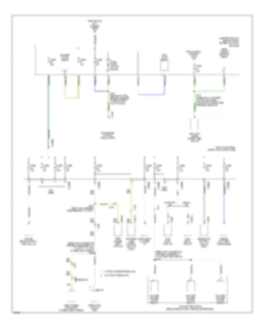
Power Distribution Wiring Diagram (5 of 6) for Ford Expedition Limited 2014
List of elements for Power Distribution Wiring Diagram (5 of 6) for Ford Expedition Limited 2014:
- (center front of engine compt) battery junction box (bjb)
- (not used)
- (rear light connector harness, in breakout to auxiliary relay box 2) s420
- (rear light connector harness, near breakout to left "c" pillar)
- (right kick panel) smart junction box (sjb)
- (w/ rear view camera) s408
- Anti-lock brake system (abs) module
- Automatic a/c
- Auxiliary blower motor relay 1
- Auxiliary blower motor relay 2
- Auxiliary blower motor relay 3
- Auxiliary relay box 2 (behind rear of right rear quarterpanel)
- Blower motor relay
- C175b
- C210
- C2280b
- C2280d
- C2280e
- C228a
- C2357a
- C2371a
- C3054b
- C310a
- C314
- C4014a
- C411
- C438 (expedition)
- C465
- C919
- From fuse 53 (diagram 1 of 6) c
- From splice s117 (diagram 1 of 6)
- Fuel pump motor diode
- Fuel pump relay
- Fuse 10a
- Fuse 30a
- Fuse 5a
- Fuse 7.5a
- Hvac (datc) module
- Hvac (emtc) module
- Instrument cluster (ic)
- Manual a/c
- Parking aid module (pam)
- Passive anti-theft transceiver
- Powertrain control module (pcm)
- Rear heated seat module
- Rear window defrost relay
- Restraints control module (rcm)
- S119 (expedition: in battery junction box (bjb)) (navigator: on rear dash harness, near g201)
- S120 (engine control sensor harness, under battery junction box)
- S316 (body main harness, near breakout to g301)
- Tan
- Trailer brake control (tbc) module
- Transfer case control module (tccm)
- Video camera (navigation w/ rear video camera)
- W/ front & rear parking aid
- W/o front parking aid
Power Distribution Wiring Diagram (6 of 6) for Ford Expedition Limited 2014
List of elements for Power Distribution Wiring Diagram (6 of 6) for Ford Expedition Limited 2014:
- (center front of engine compt) battery junction box (bjb)
- (engine control sensor & fuel charge harness, near breakout top of right cylinder head)
- (engine control sensor harness, near breakout to front of engine compt)
- (engine control sensor harness, near top left rear of engine) s155
- (engine control sensor harness, under battery junction box) s116
- (on rear engine harness, near breakout to c144) s156
- (top front of engine, near breakout to coil on plug 3 connector) s158
- A/c clutch relay
- C145
- C146
- C175b
- C213
- C2239
- C315
- Coil on plug (cop) 1
- Coil on plug (cop) 2
- Coil on plug (cop) 3
- Coil on plug (cop) 4
- Coil on plug (cop) 5
- Coil on plug (cop) 6
- Coil on plug (cop) 7
- Coil on plug (cop) 8
- Evaporative emission (evap) canister purge valve
- Fan control (fc) relay
- Floor shifter
- From k fuse 16 (diagram 2 of 6)
- Fuse 15a
- Fuse 20a
- Fuse 30a
- Heated oxygen sensor (ho2s) 12
- Heated oxygen sensor (ho2s) 22
- High fan control (hfc) relay
- Ignition transformer capacitor 1
- Ignition transformer capacitor 2
- Low fan control (lfc) relay
- Mass air flow intake air temperature (maf/iat) sensor
- Nca
- Pcm power relay
- Powertrain control module (pcm)
- Reversing lamp relay
- S111 (engine control sensor harness, near breakout to front of engine compt)
- S123
- S127 (engine control sensor harness, near breakout to left rear of engine compt)
- S143
- Tow haul switch
- Universal heated oxygen sensor (ho2s) 11
- Universal heated oxygen sensor (ho2s) 21
- Variable camshaft timing (vct) solenoid 1
- Variable camshaft timing (vct) solenoid 2
- W/ column shifter

 Čeština
 Dansk
Dansk Deutsch
 Ελληνικά
 English
 English
 Español
 Suomi
Suomi Français
 Français
 עברית
עברית Hrvatski
 Magyar
 Italiano
 日本語
日本語 한국어
한국어 Nederlands
 Polski
 Português
 Română
 Русский
 Slovenčina
 Slovenščina
 Svenska
 Türkçe
 中文 (中国)