SHIFT INTERLOCK
Shift Interlock Wiring Diagram for Saturn L200 2003
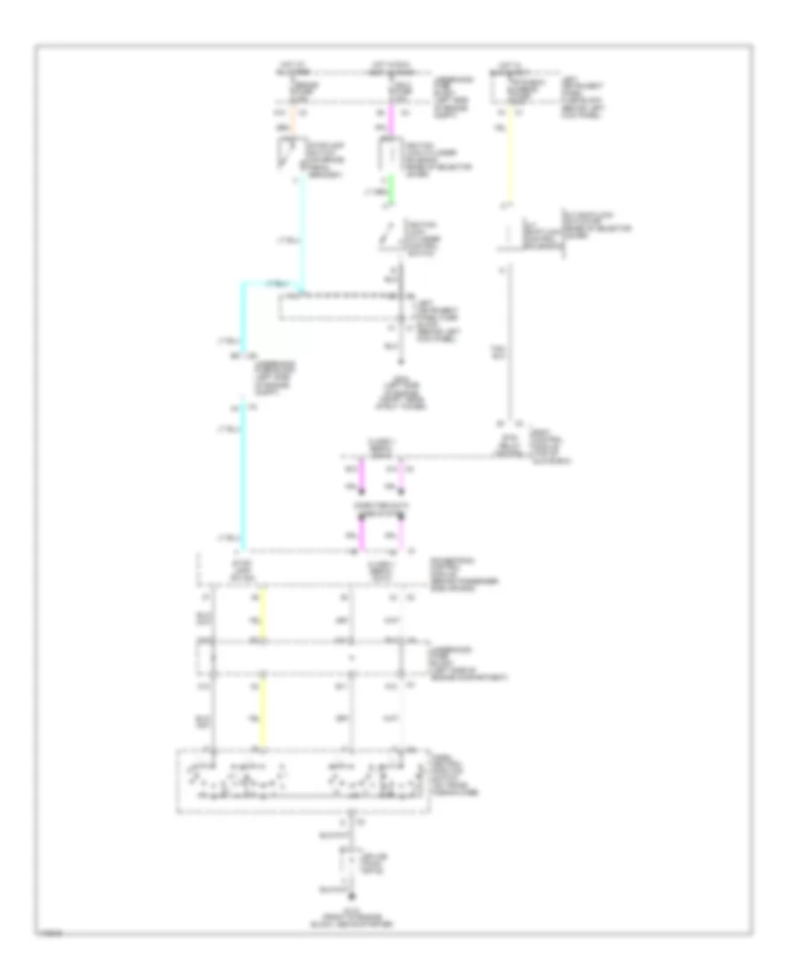
List of elements for Shift Interlock Wiring Diagram for Saturn L200 2003:
- A/t shiftlock actuator (base of selector lever)
- A/t shiftlock control solendoid
- A10
- A12
- B10
- B12
- Body control module (top of glove box)
- Brake fuse 15a
- Btsi relay control
- Btsi/bcm/ mirror fuse 10a
- C12
- C3 c3
- Class ii serial data
- Computer data lines system
- D11
- D12
- E11
- F10
- G118 (front of engine block, above starter)
- G304 (left side of engine compt, near strut tower)
- Hot at all times
- Hot in run & accy
- Hot in run, accy & crank
- Ign 0 fuse 10a
- Ignition lock cylinder control switch
- Ignition lock cylinder solenoid (base of selector lever)
- Left instrument panel fuse block (behind left kick panel)
- Park/ neutral position switch (on trans- mission case)
- Powertrain control module (behind passenger side air bag)
- Splice pack sp120
- Stop- lamp sw sig
- Stoplamp switch (on brake pedal bracket)
- Underhood fuse block (left side of engine compartment)
- Underhood fuse block (left side of engine compt)
 Čeština
 Dansk
Dansk Deutsch
 Ελληνικά
 English
 English
 Español
 Suomi
Suomi Français
 Français
 עברית
עברית Hrvatski
 Magyar
 Italiano
 日本語
日本語 한국어
한국어 Nederlands
 Polski
 Português
 Română
 Русский
 Slovenčina
 Slovenščina
 Svenska
 Türkçe
 中文 (中国)
 Português