SUPPLEMENTAL RESTRAINTS
Supplemental Restraints Wiring Diagram for Saturn Vue 2004
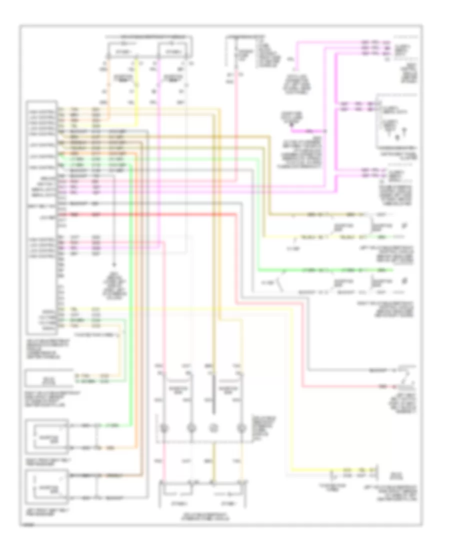
List of elements for Supplemental Restraints Wiring Diagram for Saturn Vue 2004:
- (w/ asf)
- (w/o asf)
- A c1
- A c2
- A10
- A11
- A12
- A13
- A14
- A15
- A16
- A17
- A18
- Air bag fuse 10a
- Air bag indicator
- B10
- Body control module (center of dash)
- Class 2 serial data
- Computer data lines system
- Data link connector (at left side of dash, near kick panel)
- E11
- G201 (behind lower left side of dash, left of steering column)
- Ground
- High control
- Hot in run & start
- I/p fuse block (on right front side of center console)
- Ignition 1
- Inflatable restraint ip module
- Inflatable restraint sensing & diagnostic module (under rear of center console)
- Inflatable restraint steering wheel module
- Inflatable restraint steering wheel module coil
- Instrument panel cluster
- Left front seat belt pretensioner
- Left inflatable restraint roof rail module (behind headliner, above left doors)
- Left inflatable restraint side impact sensor (at base of left center door pillar)
- Left seat belt switch (part of seat belt buckle assembly)
- Low control
- Low ref
- Nca
- Pnk
- Power steering control module (under left side of dash, behind knee bolster)
- Red
- Right front seat belt pretensioner
- Right inflatable restraint roof rail module (behind headliner, above right doors)
- Right inflatable restraint side impact sensor (at base of right center door pillar)
- S203 (in the i/p harness, between the bcm & i/p fuse block harness connector breakouts, approx 10 cm (3.94 in) from fuse block breakout)
- Seat belt sw
- Serial data
- Shorting bar
- Signal
- Solid state
- Stage 1
- Stage 2
- Tan
- Twisted pair wires
- Voltage
- W/ asf
 Čeština
 Dansk
Dansk Deutsch
 Ελληνικά
 English
 English
 Español
 Suomi
Suomi Français
 Français
 עברית
עברית Hrvatski
 Magyar
 Italiano
 日本語
日本語 한국어
한국어 Nederlands
 Polski
 Português
 Română
 Русский
 Slovenčina
 Slovenščina
 Svenska
 Türkçe
 中文 (中国)
 Português