BODY CONTROL MODULES
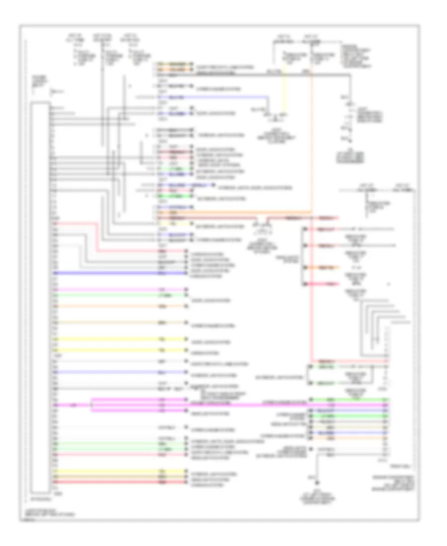
Body Control Modules Wiring Diagram, Evolution for Mitsubishi Lancer ES 2003
 https://portal-diagnostov.com/license.html
Automotive Electricians Portal FZCO
Automotive Electricians Portal FZCO
https://portal-diagnostov.com/license.html
https://portal-diagnostov.com/license.html
Automotive Electricians Portal FZCO
Automotive Electricians Portal FZCO
List of elements for Body Control Modules Wiring Diagram, Evolution for Mitsubishi Lancer ES 2003:
- (at right side of front deck crossmember) g3
- A10x
- A11x
- All times
- C210
- C214
- C217
- C218
- C226
- C227
- C228
- Computer data lines system
- Dedicated fuse 13 10a
- Dedicated fuse 16 10a
- Dedicated fuse 17 10a
- Dedicated fuse 18 10a
- Dedicated fuse 19 10a
- Dedicated fuse 20 7.5a
- Dedicated fuse 21 7.5a
- Dedicated fuse 22 10a
- Dedicated fuse 23 10a
- Door locks system
- Engine compartment relay box (on left side of engine compartment)
- Engine compartment relay box (on left side of engine compartment)
- Etacs ecu
- Exterior lights system
- Front ecu
- G13 (at left front corner of engine compartment)
- G6 (behind center of dash, near left center reinforcement)
- Headlights system
- Headlights, wiper/washer, exterior lights systems
- Horns system
- Hot at
- Hot in
- Hot in on
- Interior lights system
- Interior lights, door locks systems
- Interior lights, power windows systems
- Joint connector 1 (behind center of dash)
- Joint connector 2 (behind instrument cluster)
- Joint connector 3 (behind right side of dash)
- Junction block (behind left end of dash)
- Multi- purpose fuse 14 15a
- Multi- purpose fuse 15 15a
- Multi- purpose fuse 2 7.5a
- On or acc
- Or start
- Pnk
- Power window relay
- Red
- Warning system
- Wiper/ washer system
- Wiper/washer system
Body Control Modules Wiring Diagram, Except Evolution for Mitsubishi Lancer ES 2003
List of elements for Body Control Modules Wiring Diagram, Except Evolution for Mitsubishi Lancer ES 2003:
- A10x
- A11x
- All times
- C210
- C214
- C217
- C218
- C226
- C227
- C228
- Computer data lines system
- Dedicated fuse 13 10a
- Dedicated fuse 16 10a
- Dedicated fuse 17 10a
- Dedicated fuse 18 10a
- Dedicated fuse 19 10a
- Dedicated fuse 20 7.5a
- Dedicated fuse 21 7.5a
- Dedicated fuse 22 10a
- Dedicated fuse 23 10a
- Door locks system
- Engine compartment relay box (on left side of engine compartment)
- Engine compartment relay box (on left side of engine compartment)
- Etacs ecu
- Exterior lights system
- Front ecu
- G13 (at left front corner of engine compartment)
- G3 (at right side of front deck crossmember)
- Headlights system
- Headlights sytem
- Headlights, wiper/washer, exterior lights systems
- Horns system
- Hot at
- Hot in
- Hot in on
- Interior lights system
- Interior lights, door locks systems
- Interior lights, door locks systems
- Joint connector 1 (behind center of dash)
- Joint connector 2 (behind instrument cluster)
- Joint connector 3 (behind right side of dash)
- Junction block (behind left end of dash)
- Multi- purpose fuse 14 15a
- Multi- purpose fuse 15 15a
- Multi- purpose fuse 2 7.5a
- On or acc
- Or start
- Pnk
- Power tops system
- Power window relay
- Red
- Warning system
- Wiper/washer system

 Čeština
 Dansk
Dansk Deutsch
 Ελληνικά
 English
 English
 Español
 Suomi
Suomi Français
 Français
 עברית
עברית Hrvatski
 Magyar
 Italiano
 日本語
日本語 한국어
한국어 Nederlands
 Polski
 Português
 Română
 Русский
 Slovenčina
 Slovenščina
 Svenska
 Türkçe
 中文 (中国)