DEFOGGERS
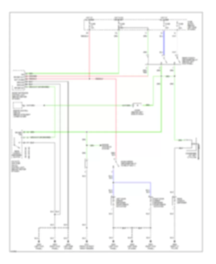
Defogger Wiring Diagram for Nissan Maxima GLE 2001
List of elements for Defogger Wiring Diagram for Nissan Maxima GLE 2001:
- 12l
- A/c auto amplifier (or a/c control unit) (behind center of dash)
- Bat (fuse)
- Condenser (at left "c" pillar)
- Diode (behind left side of dash)
- Door mirror defogger relay (in relay box 1)
- Engine control module (behind intrument lower cover)
- Engine controls system
- Fuse 10a
- Fuse 20a
- Fuse 20a
- Fuse block (behind left side of dash)
- G101 (front of right front fender)
- G200 (left kick panel)
- G202 (left side of dash)
- G203 (right kick panel)
- G905 (right "c" pillar)
- Ground
- Hot at all times
- Hot in on or start
- Ign
- Left door mirror defogger (door mirror actuator)
- Nca
- Rear window defogger
- Rear window defogger relay (behind left kick panel)
- Rear window defogger switch
- Right door mirror defogger (door mirror actuator)
- Rr def f/b
- Rr def out
- Rr def sw
- Smart entrance control unit (behind center of dash)
- W/ auto a/c
- W/o auto a/c
 Čeština
 Dansk
Dansk Deutsch
 Ελληνικά
 English
 English
 Español
 Suomi
Suomi Français
 Français
 עברית
עברית Hrvatski
 Magyar
 Italiano
 日本語
日本語 한국어
한국어 Nederlands
 Polski
 Português
 Română
 Русский
 Slovenčina
 Slovenščina
 Svenska
 Türkçe
 中文 (中国)
 Português