RADIO
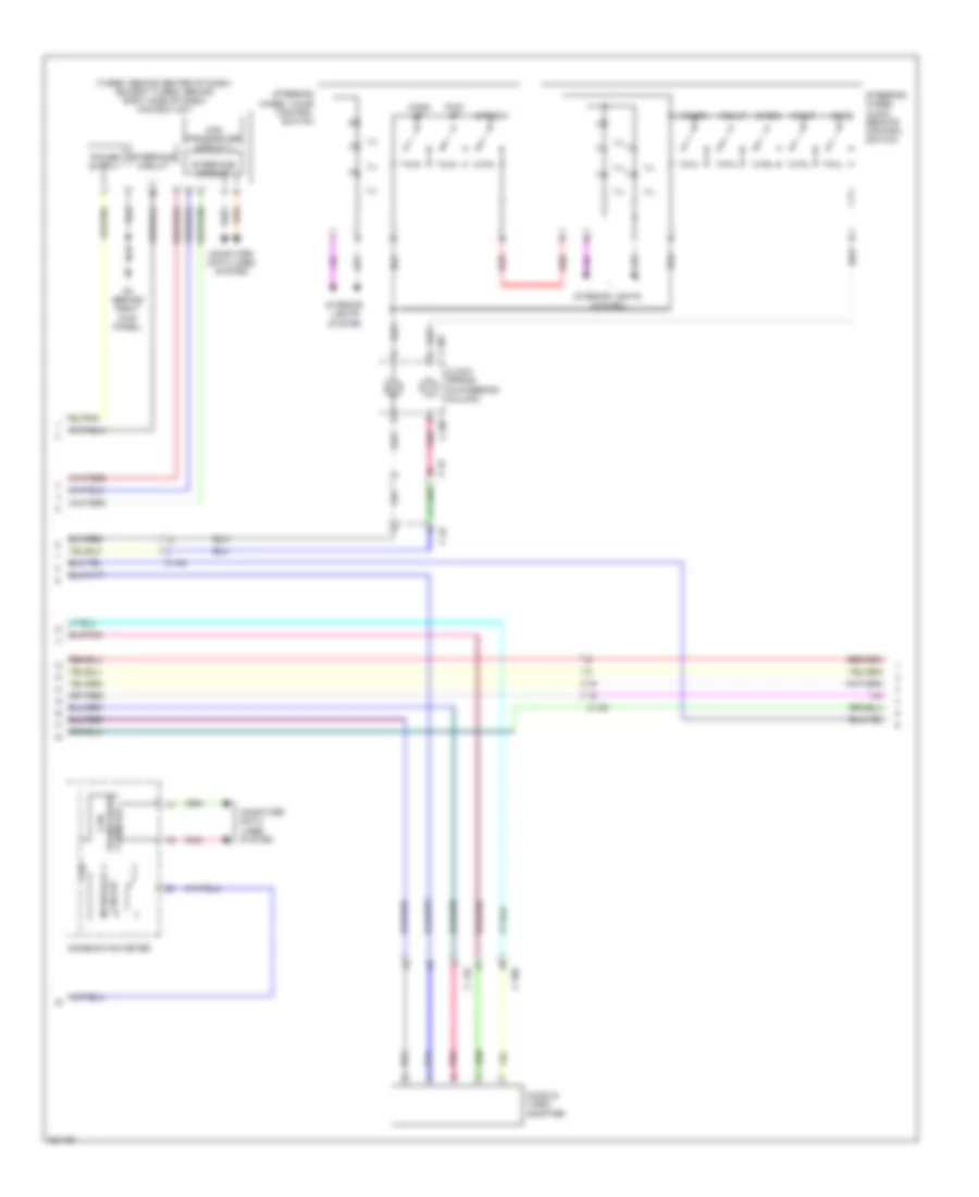
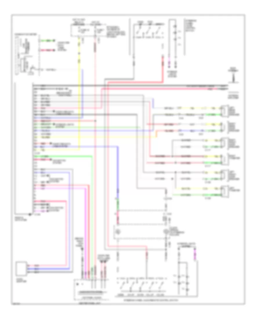
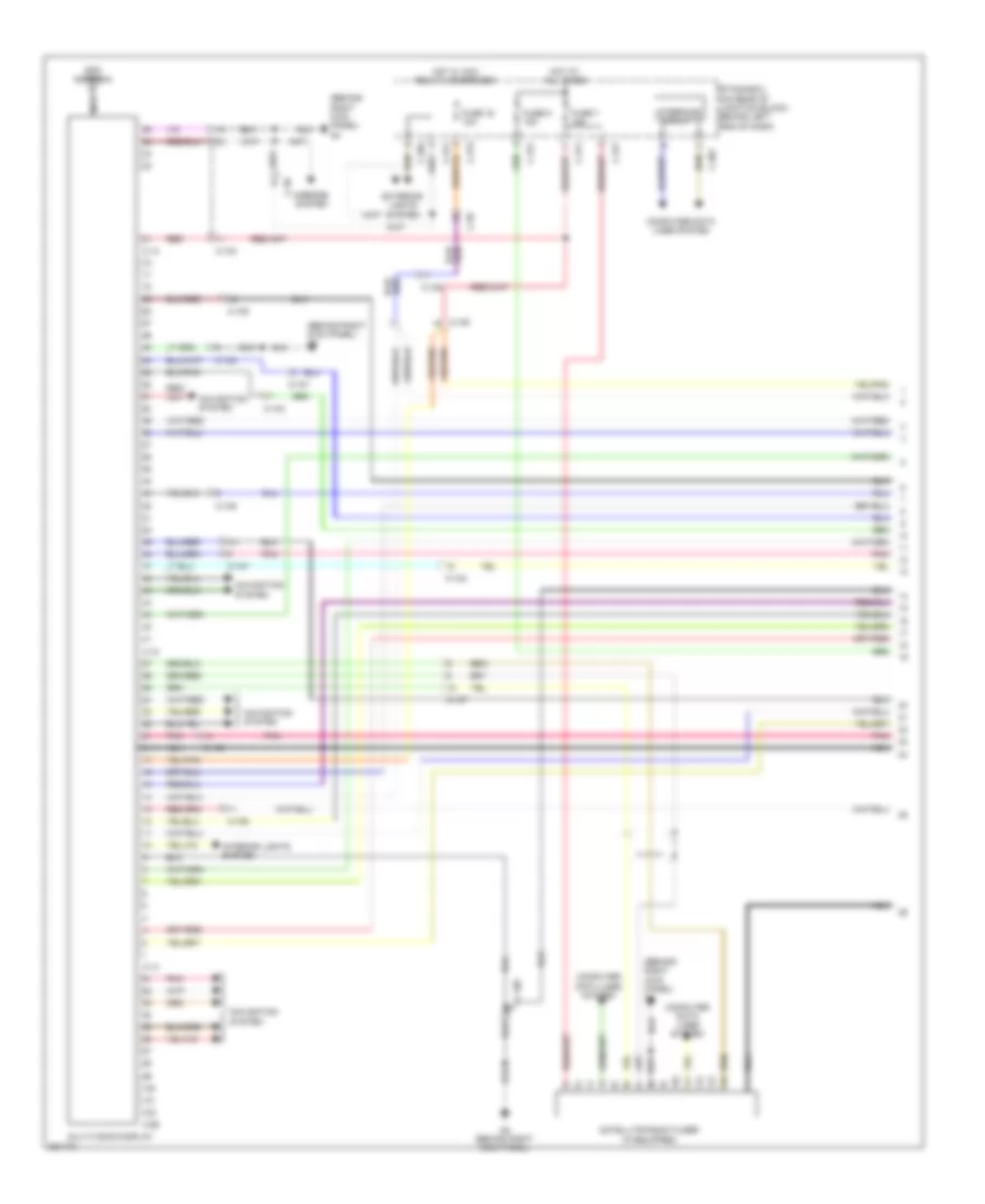
Radio Wiring Diagram, Evolution with Multi-Communication System (1 of 3) for Mitsubishi Lancer GT 2012
 https://portal-diagnostov.com/license.html
Automotive Electricians Portal FZCO
Automotive Electricians Portal FZCO
https://portal-diagnostov.com/license.html
https://portal-diagnostov.com/license.html
Automotive Electricians Portal FZCO
Automotive Electricians Portal FZCO
List of elements for Radio Wiring Diagram, Evolution with Multi-Communication System (1 of 3) for Mitsubishi Lancer GT 2012:
- (antenna feeder cable)
- (behind right kick panel) g4
- Antenna amplifier
- C-09
- C-10
- C-106
- C-108
- C-110
- C-12
- C-13
- C-304
- C-311
- C-315
- C-317
- C-42
- C108
- Cable) (gps antenna
- Computer data lines system
- Etacs-ecu (on rear of junction block, behind left end of dash)
- Exterior lights system
- Fuse 16 10a
- Fuse 7 15a
- G4 (behind right kick panel)
- Gps antenna
- Hot at all times
- Hot w/ acc relay 2 energized
- Interior lights system
- J/c c-43 (left kick panel)
- Mirrors system
- Multivision display
- Navigation system
- Nca
- Pnk
- Red
- Roof antenna
- Satellite radio tuner
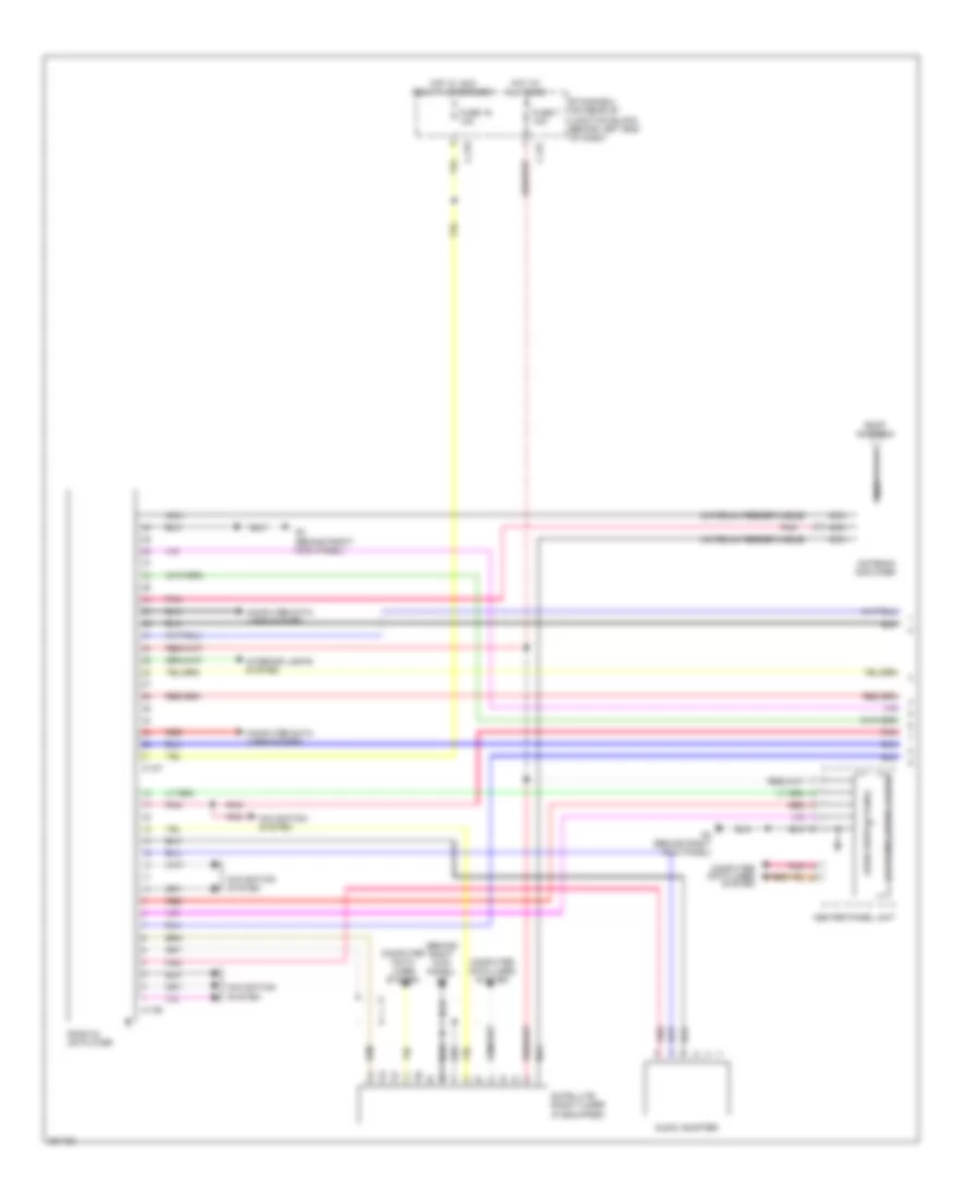
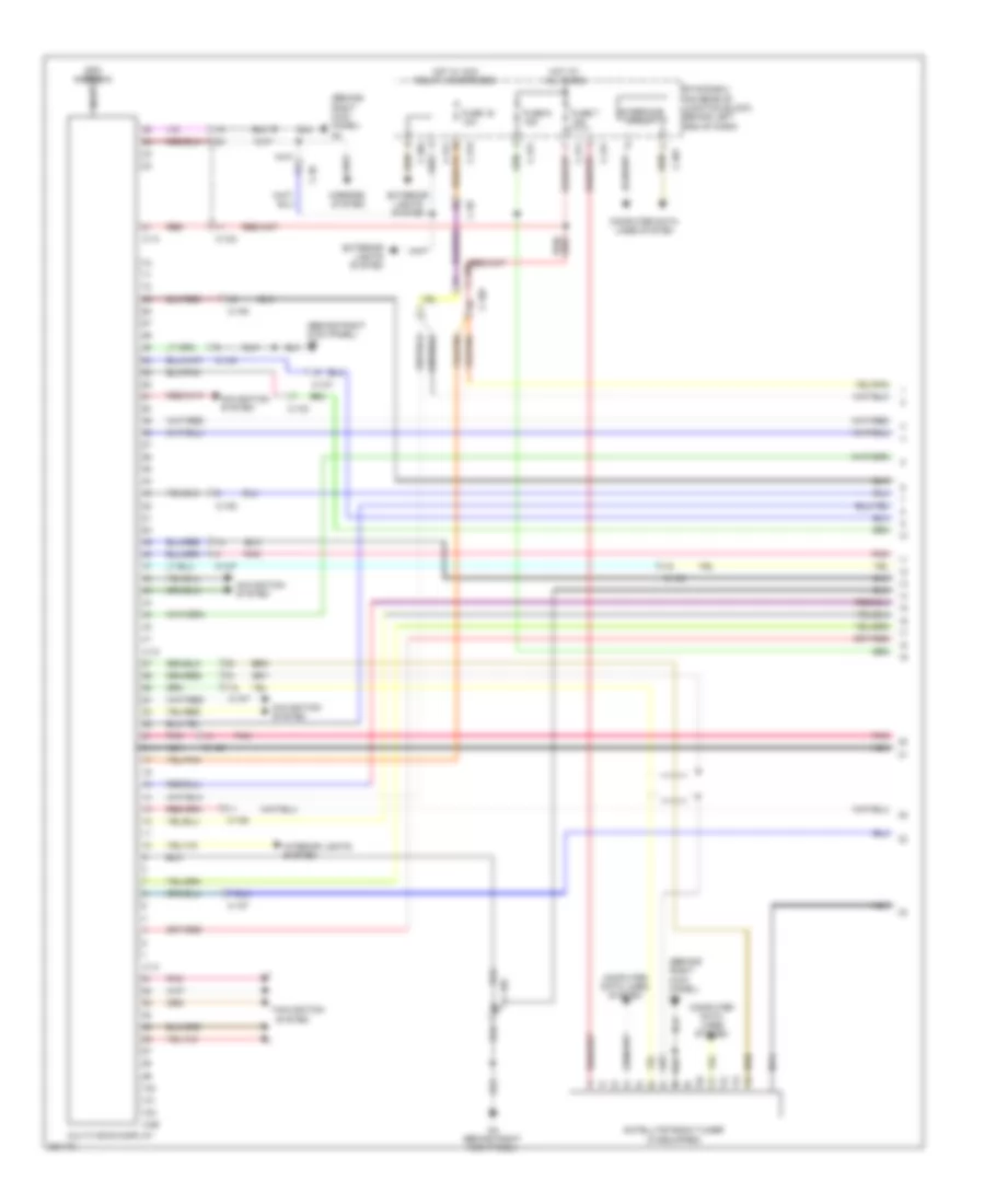
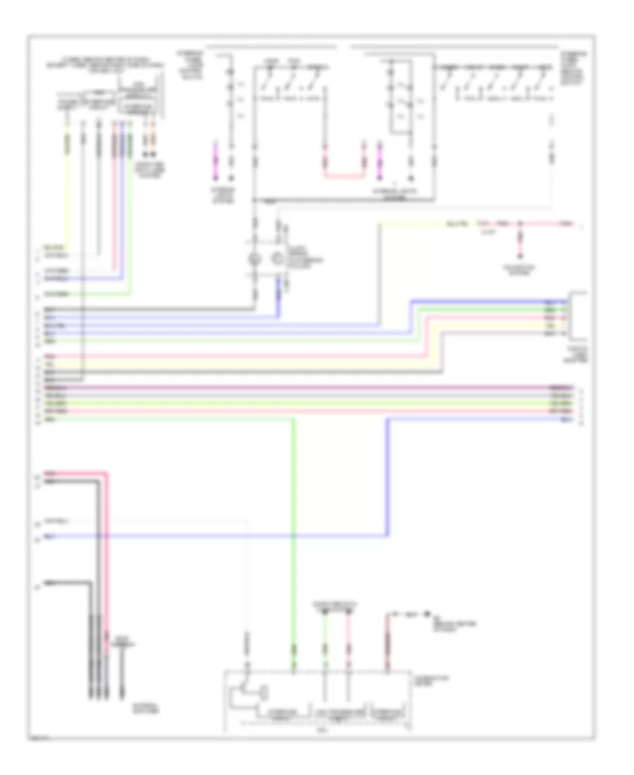
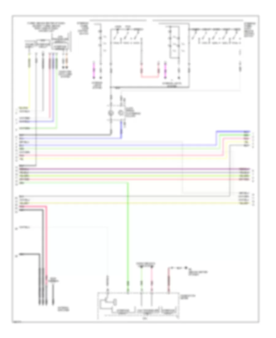
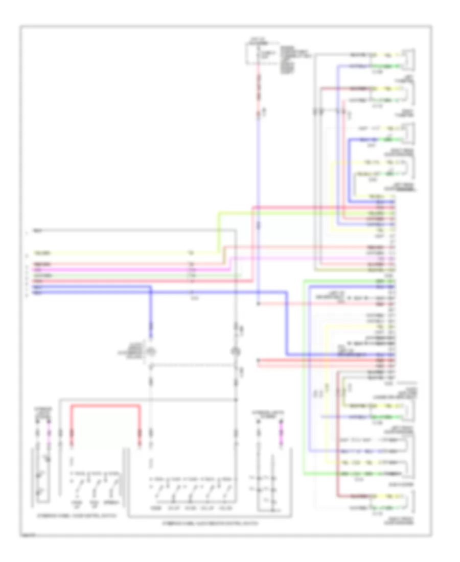
Radio Wiring Diagram, Evolution with Multi-Communication System (2 of 3) for Mitsubishi Lancer GT 2012
List of elements for Radio Wiring Diagram, Evolution with Multi-Communication System (2 of 3) for Mitsubishi Lancer GT 2012:
- (turbo: behind center of dash) (except turbo: behind right side of dash) can box unit
- Audio & video adapter
- C-106
- C-108
- C-110
- C-202
- C-205
- C-32
- Can transceiver circuit
- Ch dn
- Ch up
- Circuit interface
- Circuit transceiver can
- Clock spring (in steering column)
- Combination meter
- Computer data lines system
- Cpu
- G4 (behind right kick panel)
- Hang up
- Ill
- Interface circuit
- Interior lights system
- Mode
- Pick up
- Pnk
- Red
- Speech
- Steering wheel audio remote control switch
- Steering wheel voice control switch
- Vol dn
- Vol up
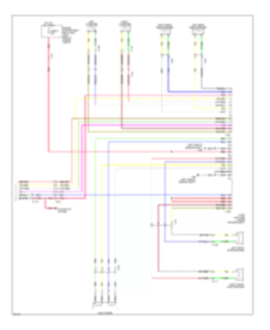
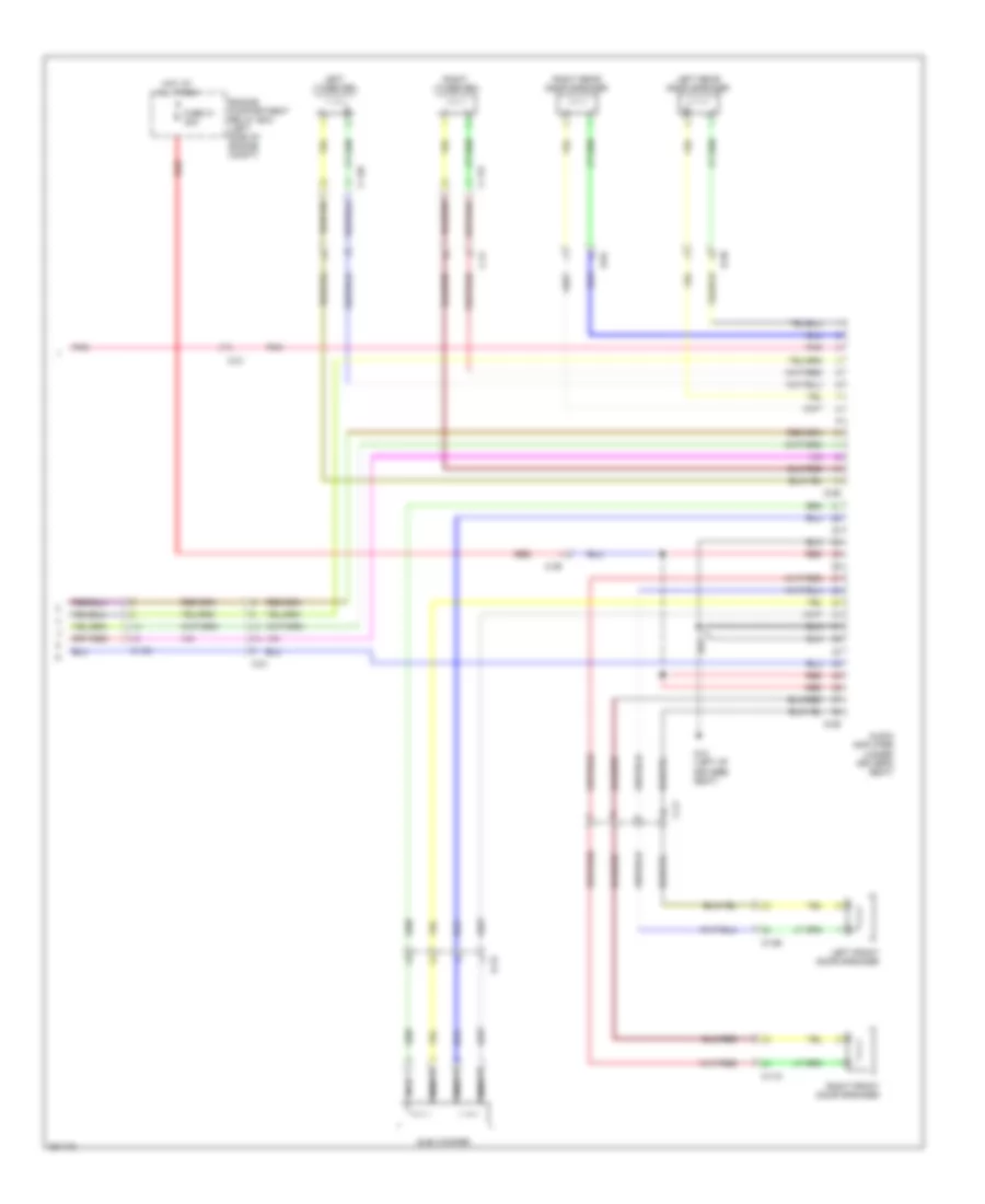
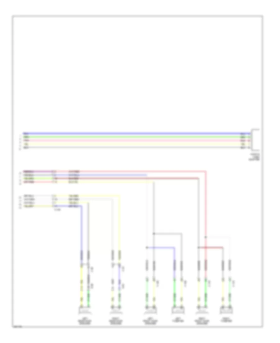
Radio Wiring Diagram, Evolution with Multi-Communication System (3 of 3) for Mitsubishi Lancer GT 2012
List of elements for Radio Wiring Diagram, Evolution with Multi-Communication System (3 of 3) for Mitsubishi Lancer GT 2012:
- (left side of engine compt) g20
- Audio amplifier (under driver's seat)
- C-110
- C-117
- C-129
- C-24
- C-47
- D-01
- D-16
- D-24
- D-29
- D-30
- Engine compartment relay box (left side of engine compt)
- Fuse 31 30a
- G20 (left side of engine compt)
- Hot at all times
- Left front door speaker
- Left rear door speaker
- Left tweeter
- Navigation system
- Nca
- Pnk
- Red
- Right front door speaker
- Right rear door speaker
- Right tweeter
- Sub woofer
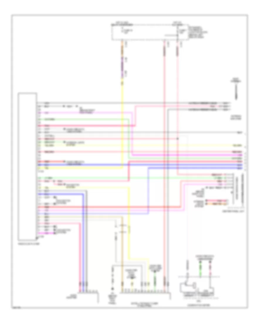
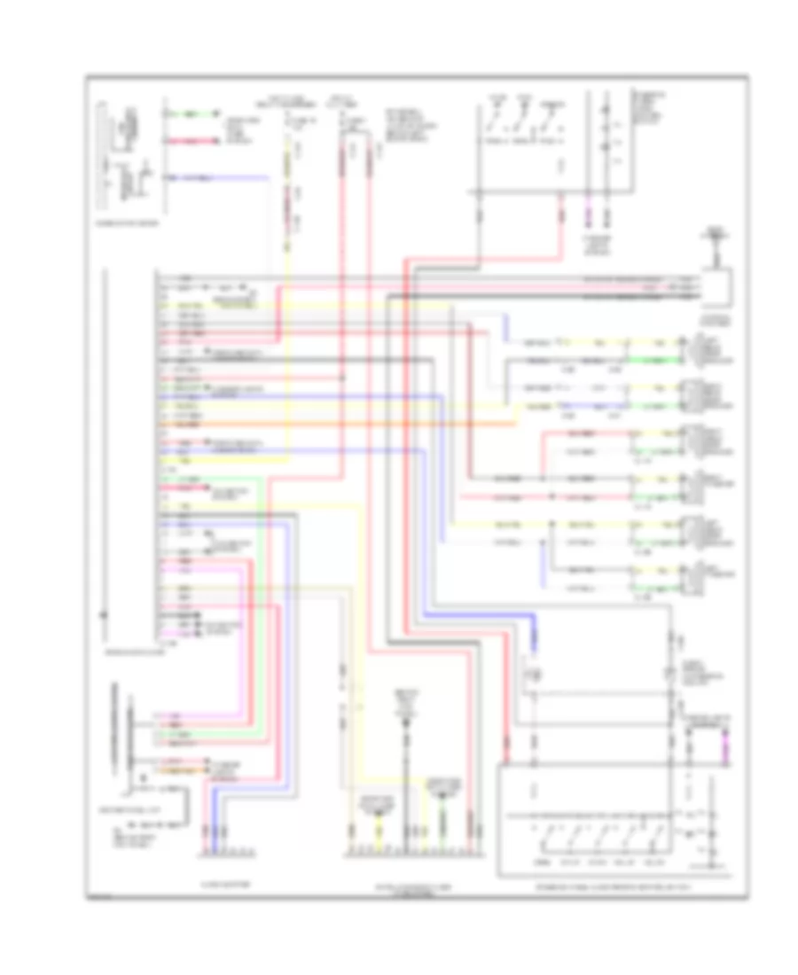
Radio Wiring Diagram, Evolution without Multi-Communication System with Amplifier (1 of 2) for Mitsubishi Lancer GT 2012
List of elements for Radio Wiring Diagram, Evolution without Multi-Communication System with Amplifier (1 of 2) for Mitsubishi Lancer GT 2012:
- (antenna feeder cable)
- (behind right kick panel) g4
- Antenna amplifier
- Audio adapter
- Audio switch panel
- C-107
- C-109
- C-315
- C-317
- Center panel unit
- Computer data lines system
- Etacs-ecu (on rear of junction block, behind left end of dash)
- Fuse 16 10a
- Fuse 7 15a
- G4 (behind right kick panel)
- Hot at all times
- Hot w/ acc relay 2 energized
- Interior lights system
- Lcd panel (audio, clock)
- Navigation system
- Nca
- Pnk
- Radio & cd player
- Red
- Roof antenna
- Satellite radio tuner (if equipped)
Radio Wiring Diagram, Evolution without Multi-Communication System with Amplifier (2 of 2) for Mitsubishi Lancer GT 2012
List of elements for Radio Wiring Diagram, Evolution without Multi-Communication System with Amplifier (2 of 2) for Mitsubishi Lancer GT 2012:
- Audio amplifier (under driver's seat)
- C-117
- C-129
- C-202
- C-205
- C-24
- C-32
- C-47
- Ch dn
- Ch up
- Circuit interface
- Circuit transceiver can
- Clock spring (in steering column)
- Combination meter
- Computer data lines system
- Cpu
- D-01
- D-16
- D-24
- D-29
- D-30
- Engine compartment relay box (left side of engine compt)
- Fuse 31 30a
- G20 (left side of engine compt)
- Hang up
- Hot at all times
- Ill
- Interior lights system
- Left front door speaker
- Left rear door speaker
- Left tweeter
- Mode
- Nca
- Pick up
- Pnk
- Red
- Right front door speaker
- Right rear door speaker
- Right tweeter
- Speech
- Steering wheel audio remote control switch
- Steering wheel voice control switch
- Sub woofer
- Vol dn
- Vol up
Radio Wiring Diagram, Evolution without Multi-Communication System without Amplifier for Mitsubishi Lancer GT 2012
List of elements for Radio Wiring Diagram, Evolution without Multi-Communication System without Amplifier for Mitsubishi Lancer GT 2012:
- (antenna feeder cable)
- (behind right kick panel) g4
- Antenna amplifier
- Audio adapter
- Audio switch panel
- C-107
- C-109
- C-117
- C-129
- C-202
- C-205
- C-23
- C-315
- C-317
- C-32
- C-42
- Can transceiver circuit
- Center panel unit
- Ch dn
- Ch up
- Clock spring (in steering column)
- Combination meter
- Computer data lines system
- Cpu
- D-01
- D-24
- Etacs-ecu (on rear of junction block, behind left end of dash)
- Fuse 16 10a
- Fuse 7 15a
- G4 (behind right kick panel)
- Hang up
- Hot at all times
- Hot w/ acc relay 2 energized
- Ill
- Interface circuit
- Interior lights system
- Lcd panel (audio)
- Left front door speaker
- Left rear door speaker
- Left tweeter
- Mode
- Navigation system
- Nca
- Pick up
- Pnk
- Radio & cd player
- Red
- Right front door speaker
- Right rear door speaker
- Right tweeter
- Roof antenna
- Speech
- Steering wheel audio remote control switch
- Steering wheel voice control switch
- Vol dn
- Vol up
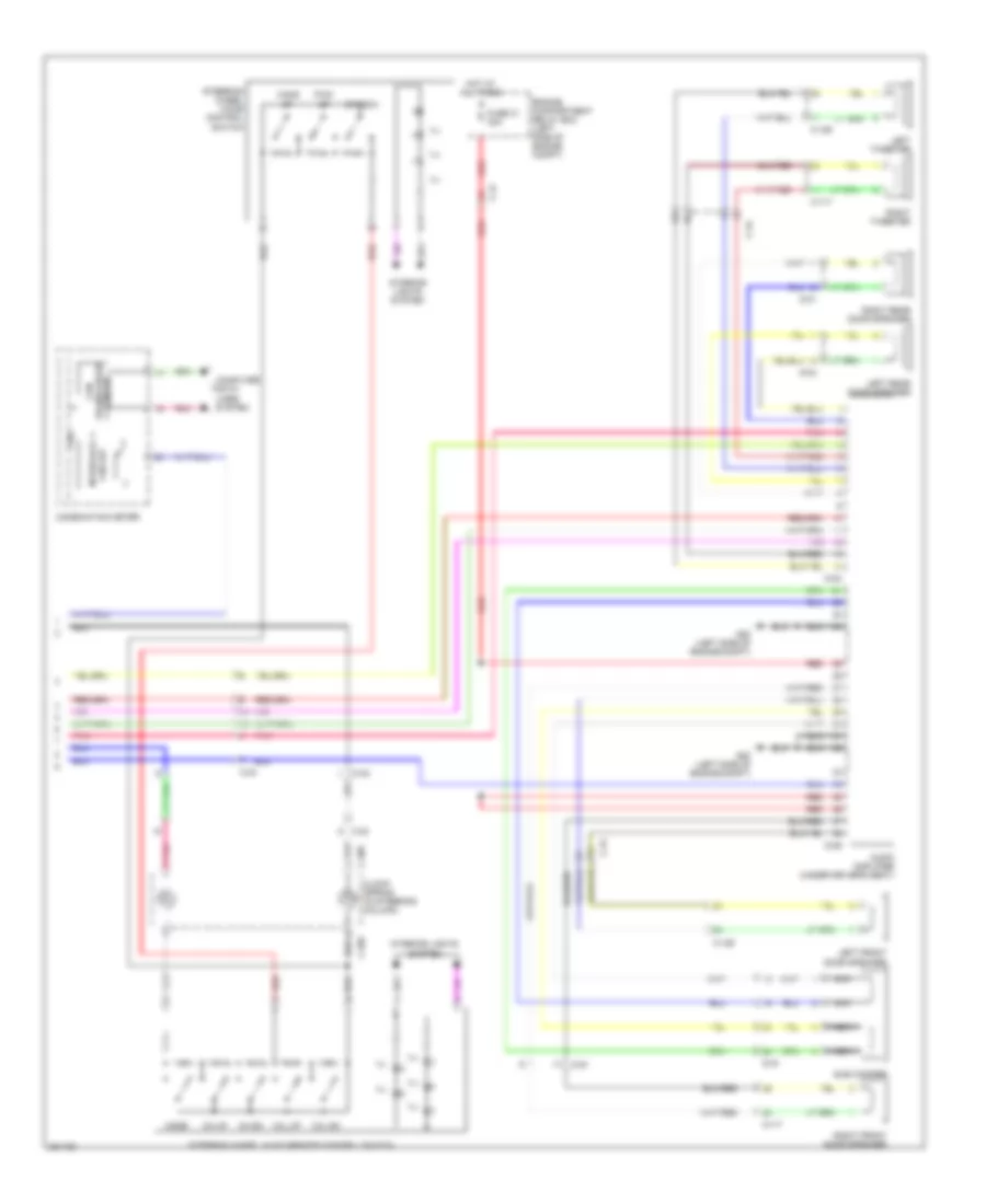
Radio Wiring Diagram, Except Evolution with Multi-Communication System with Amplifier (1 of 3) for Mitsubishi Lancer GT 2012
List of elements for Radio Wiring Diagram, Except Evolution with Multi-Communication System with Amplifier (1 of 3) for Mitsubishi Lancer GT 2012:
- (behind right kick panel) g4
- C-103
- C-105
- C-107
- C-11
- C-12
- C-128
- C-13
- C-14
- C-301
- C-304
- C-311
- C-313
- C-317
- C-36
- C-39
- C-59
- Computer data lines system
- Etacs-ecu (on rear of junction block, behind left end of dash)
- Exterior lights system
- Fuse 16 10a
- Fuse 7 15a
- Fuse 9 15a
- G4 (behind right kick panel)
- Gps antenna
- Hot at all times
- Hot w/ acc relay 2 energized
- Interface circuit
- Interior lights system
- Mirrors system
- Multivision display
- Navigation system
- Nca
- Pnk
- Red
- Satellite radio tuner (if equipped)
Radio Wiring Diagram, Except Evolution with Multi-Communication System with Amplifier (2 of 3) for Mitsubishi Lancer GT 2012
List of elements for Radio Wiring Diagram, Except Evolution with Multi-Communication System with Amplifier (2 of 3) for Mitsubishi Lancer GT 2012:
- (antenna feeder cable)
- (turbo: behind center of dash) (except turbo: behind right side of dash) can box unit
- Acc
- Antenna amplifier
- Audio & video adapter
- C-107
- C-204
- C-205
- Can transceiver circuit
- Ch dn
- Ch up
- Clock spring (in steering column)
- Combination meter
- Computer data lines system
- Cpu
- G6 (behind center of dash)
- Hang up
- Ill
- Interface circuit
- Interior lights system
- Mode
- Navigation system
- Nca
- Pick up
- Pnk
- Red
- Roof antenna
- Speech
- Steering wheel audio remote control switch
- Steering wheel voice control switch
- Vol dn
- Vol up
Radio Wiring Diagram, Except Evolution with Multi-Communication System with Amplifier (3 of 3) for Mitsubishi Lancer GT 2012
List of elements for Radio Wiring Diagram, Except Evolution with Multi-Communication System with Amplifier (3 of 3) for Mitsubishi Lancer GT 2012:
- Audio amplifier (under driver's seat)
- C-105
- C-115
- C-126
- C-21
- C-39
- D-01
- D-15
- D-20
- D-25
- D-26
- Engine compartment relay box (left side of engine compt)
- Fuse 31 30a
- G12 (left of drivers seat)
- Hot at all times
- Left front door speaker
- Left rear door speaker
- Left tweeter
- Nca
- Pnk
- Red
- Right front door speaker
- Right rear door speaker
- Right tweeter
- Sub woofer
Radio Wiring Diagram, Except Evolution with Multi-Communication System without Amplifier (1 of 3) for Mitsubishi Lancer GT 2012
List of elements for Radio Wiring Diagram, Except Evolution with Multi-Communication System without Amplifier (1 of 3) for Mitsubishi Lancer GT 2012:
- (behind right kick panel) g4
- C-103
- C-105
- C-107
- C-11
- C-12
- C-128
- C-13
- C-14
- C-301
- C-304
- C-311
- C-313
- C-317
- C-36
- C-39
- C-59
- Computer data lines system
- Etacs-ecu (on rear of junction block, behind left end of dash)
- Exterior lights system
- Fuse 16 10a
- Fuse 7 15a
- Fuse 9 15a
- G4 (behind right kick panel)
- Gps antenna
- Hot at all times
- Hot w/ acc relay 2 energized
- Interface circuit
- Interior lights system
- Mirrors system
- Multivision display
- Navigation system
- Nca
- Pnk
- Red
- Satellite radio tuner (if equipped)
Radio Wiring Diagram, Except Evolution with Multi-Communication System without Amplifier (2 of 3) for Mitsubishi Lancer GT 2012
List of elements for Radio Wiring Diagram, Except Evolution with Multi-Communication System without Amplifier (2 of 3) for Mitsubishi Lancer GT 2012:
- (antenna feeder cable)
- (turbo: behind center of dash) (except turbo: behind right side of dash) can box unit
- Acc
- Antenna amplifier
- C-204
- C-205
- Can transceiver circuit
- Ch dn
- Ch up
- Clock spring (in steering column)
- Combination meter
- Computer data lines system
- Cpu
- G6 (behind center of dash)
- Hang up
- Ill
- Interface circuit
- Interior lights system
- Mode
- Nca
- Pick up
- Pnk
- Red
- Roof antenna
- Speech
- Steering wheel audio remote control switch
- Steering wheel voice control switch
- Vol dn
- Vol up
Radio Wiring Diagram, Except Evolution with Multi-Communication System without Amplifier (3 of 3) for Mitsubishi Lancer GT 2012
List of elements for Radio Wiring Diagram, Except Evolution with Multi-Communication System without Amplifier (3 of 3) for Mitsubishi Lancer GT 2012:
- Audio & video adapter
- C-105
- C-115
- C-126
- C-22
- C-36
- D-01
- D-20
- Left front door speaker
- Left rear door speaker
- Left tweeter
- Pnk
- Right front door speaker
- Right rear door speaker
- Right tweeter
Radio Wiring Diagram, Except Evolution without Multi-Communication System with Amplifier (1 of 2) for Mitsubishi Lancer GT 2012
List of elements for Radio Wiring Diagram, Except Evolution without Multi-Communication System with Amplifier (1 of 2) for Mitsubishi Lancer GT 2012:
- (antenna feeder cable)
- Antenna amplifier
- Audio adapter
- Audio switch panel
- Behind left end of dash)
- C-104
- C-106
- C-128
- C-311
- C-313
- C-317
- C-39
- Can transceiver circuit
- Center panel unit
- Combination meter
- Computer data lines system
- Cpu
- Etacs-ecu (on rear of junction block,
- Fuse 16 10a
- Fuse 7 15a
- G4 (behind right kick panel)
- Hot at all times
- Hot w/ acc relay 2 energized
- Interface circuit
- Interior lights system
- Lcd panel (audio, clock)
- Navigation system
- Nca
- Pnk
- Radio & cd player
- Red
- Roof antenna
- Satellite radio tuner (if equipped)
Radio Wiring Diagram, Except Evolution without Multi-Communication System with Amplifier (2 of 2) for Mitsubishi Lancer GT 2012
List of elements for Radio Wiring Diagram, Except Evolution without Multi-Communication System with Amplifier (2 of 2) for Mitsubishi Lancer GT 2012:
- (left of driver's seat) g12
- Audio amplifier (under driver's seat)
- C-115
- C-126
- C-204
- C-205
- C-21
- C-39
- Ch dn
- Ch up
- Clock spring (in steering column)
- D-01
- D-15
- D-20
- D-25
- D-26
- Engine compartment fuse/relay box (left side of engine compt)
- Fuse 31 30a
- G12 (left of driver's seat)
- Hang up
- Hot at all times
- Ill
- Interior lights system
- Left front door speaker
- Left rear door speaker
- Left tweeter
- Mode
- Nca
- Pick up
- Pnk
- Red
- Right front door speaker
- Right rear door speaker
- Right tweeter
- Speech
- Steering wheel audio remote control switch
- Steering wheel voice control switch
- Sub woofer
- Vol dn
- Vol up
Radio Wiring Diagram, Except Evolution without Multi-Communication System without Amplifier for Mitsubishi Lancer GT 2012
List of elements for Radio Wiring Diagram, Except Evolution without Multi-Communication System without Amplifier for Mitsubishi Lancer GT 2012:
- (antenna feeder cable)
- (behind right kick panel) g4
- Antenna amplifier
- Audio adapter
- Audio switch panel
- C-104
- C-106
- C-115
- C-126
- C-128
- C-204
- C-205
- C-22
- C-311
- C-313
- C-317
- C-36
- C-39
- Can
- Center panel unit
- Ch dn
- Ch up
- Clock spring (in steering column)
- Combination meter
- Computer data lines system
- Cpu
- D-01
- D-20
- Etacs-ecu (on rear of junction block, behind left end of dash)
- Fuse 16 10a
- Fuse 7 15a
- G4 (behind right kick panel)
- Hang up
- Hot at all times
- Hot w/ acc relay 2 energized
- Ill
- Interface circuit
- Interior lights system
- Lcd panel (audio, clock)
- Left front door speaker
- Left rear door speaker
- Left tweeter
- Mode
- Navigation system
- Nca
- Pick up
- Pnk
- Radio & cd player
- Red
- Right front door speaker
- Right rear door speaker
- Right tweeter
- Roof antenna
- Satellite radio tuner (if equipped)
- Speech
- Steering wheel audio remote control switch
- Steering wheel voice control switch
- Transceiver circuit
- Vol dn
- Vol up

 Čeština
 Dansk
Dansk Deutsch
 Ελληνικά
 English
 English
 Español
 Suomi
Suomi Français
 Français
 עברית
עברית Hrvatski
 Magyar
 Italiano
 日本語
日本語 한국어
한국어 Nederlands
 Polski
 Português
 Română
 Русский
 Slovenčina
 Slovenščina
 Svenska
 Türkçe
 中文 (中国)