ANTI-LOCK BRAKES
Anti-lock Brakes Wiring Diagram for Volkswagen CC Sport 2014
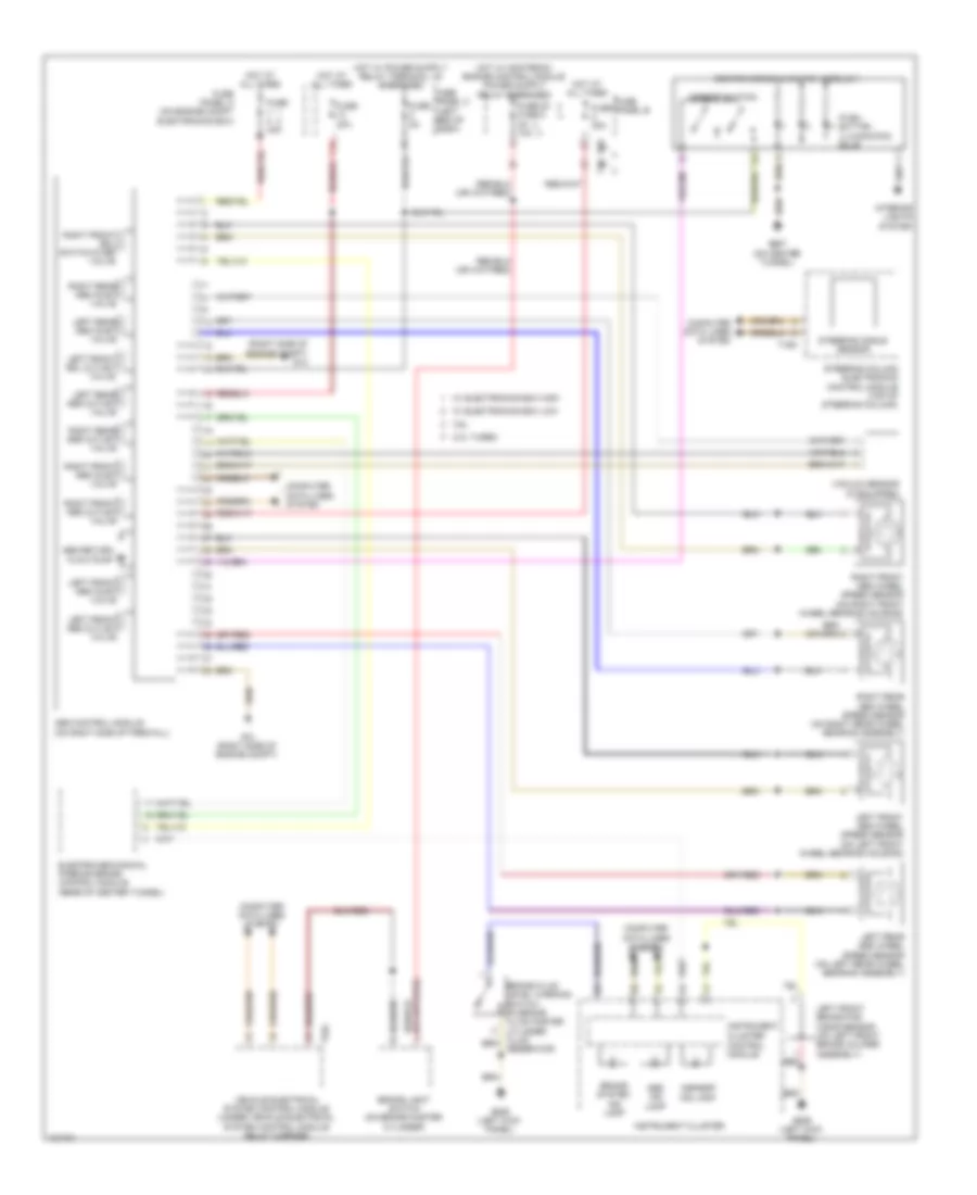
List of elements for Anti-lock Brakes Wiring Diagram for Volkswagen CC Sport 2014:
- (right side of engine compt) g13
- 13a
- 2.0l turbo
- 3.6l
- Abs control module (on right side of firewall)
- Abs ind lamp
- Abs return flow pump
- Asr/esp button
- Asr/esp ind lamp
- Brake light switch (on brake master cylinder)
- Brake system ind lamp
- Center console switch module 1
- Cluster
- Computer data lines system
- Control module
- Electro-mechanical parking brake control module (rear of center tunnel)
- Fuse 20 fuse 8 5a 10a
- Fuse 20a
- Fuse 30a
- Fuse 40a
- Fuse 5a
- Fuse panel a (on engine compt electronics box)
- Fuse panel b
- Fuse panel c (left end of dash)
- G13 (right side of engine compt)
- G639 (left kick panel)
- G687 (on center tunnel)
- Hot at all times
- Instrument
- Instrument cluster
- Interior lights system
- Left front abs inlet valve
- Left front abs outlet valve
- Left front abs wheel speed sensor (on left front wheel bearing housing)
- Left front brake pad wear sensor (on left front brake caliper assembly)
- Left front edl outlet valve
- Left rear abs inlet valve
- Left rear abs outlet valve
- Left rear abs wheel speed sensor (on left rear wheel bearing assembly)
- Push button illumination bulb
- Red
- Reservoir)
- Right front abs inlet valve
- Right front abs outlet valve
- Right front abs wheel speed sensor (on right front wheel bearing housing)
- Right front edl switch-over valve
- Right rear abs inlet valve
- Right rear abs outlet valve
- Right rear abs wheel speed sensor (on right rear wheel bearing assembly)
- Steering angle sensor
- Steering column electronics control module (top of steering column)
- T16o
- T40
- T52c
- Vacuum sensor (if equipped)
- Vehicle electrical system control module (under vehicle electrical system control module relay carrier)
- W/ electronics box high
- W/ electronics box low
 Čeština
 Dansk
Dansk Deutsch
 Ελληνικά
 English
 English
 Español
 Suomi
Suomi Français
 Français
 עברית
עברית Hrvatski
 Magyar
 Italiano
 日本語
日本語 한국어
한국어 Nederlands
 Polski
 Português
 Română
 Русский
 Slovenčina
 Slovenščina
 Svenska
 Türkçe
 中文 (中国)
 Português