СИСТЕМА ОХЛАЖДЕНИЯ
Электросхема системы охлаждения для Mercedes-Benz ML500 2003
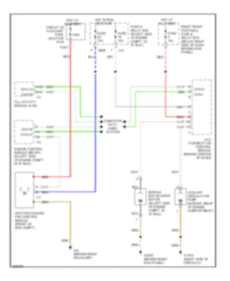
Электросхема системы охлаждения для Mercedes-Benz ML500 2003 - Список элементов:
- 100a
- A12
- Aac pushbutton control module (behind center of dash)
- All activity module (aam)
- B12
- C/c
- Can h
- Can hi
- Can l
- Can lo
- Circuit 30 auxiliary fuse (suction fan)
- Computer data lines system
- Coolant circulation pump (in right rear of engine compartment)
- Engine control module (me-sfi) (in left side of engine compt in "e" box)
- F24/7
- Fuse & relay box (in left side of engine compt, in "e" box)
- Fuse 15a
- Hot at all times
- Hot in run or start
- Module box blower motor (in left side of engine compt, in "e" box)
- Mr/e
- Nca
- Red
- Right front footwell fuse & relay box (below right side of dash, behind kick panel)
- Suction cooling fan control module (front of eng compt)
- W16/4 (right side of firewall)
- W2 (behind right headlamp)
- W29/2 (behind right kick panel)
 Čeština
 Dansk
Dansk Deutsch
 Ελληνικά
 English
 English
 Español
 Suomi
Suomi Français
 Français
 עברית
עברית Hrvatski
 Magyar
 Italiano
 日本語
日本語 한국어
한국어 Nederlands
 Polski
 Português
 Română
 Русский
 Slovenčina
 Slovenščina
 Svenska
 Türkçe
 中文 (中国)
 Português