ENGINE PERFORMANCE
5.7L
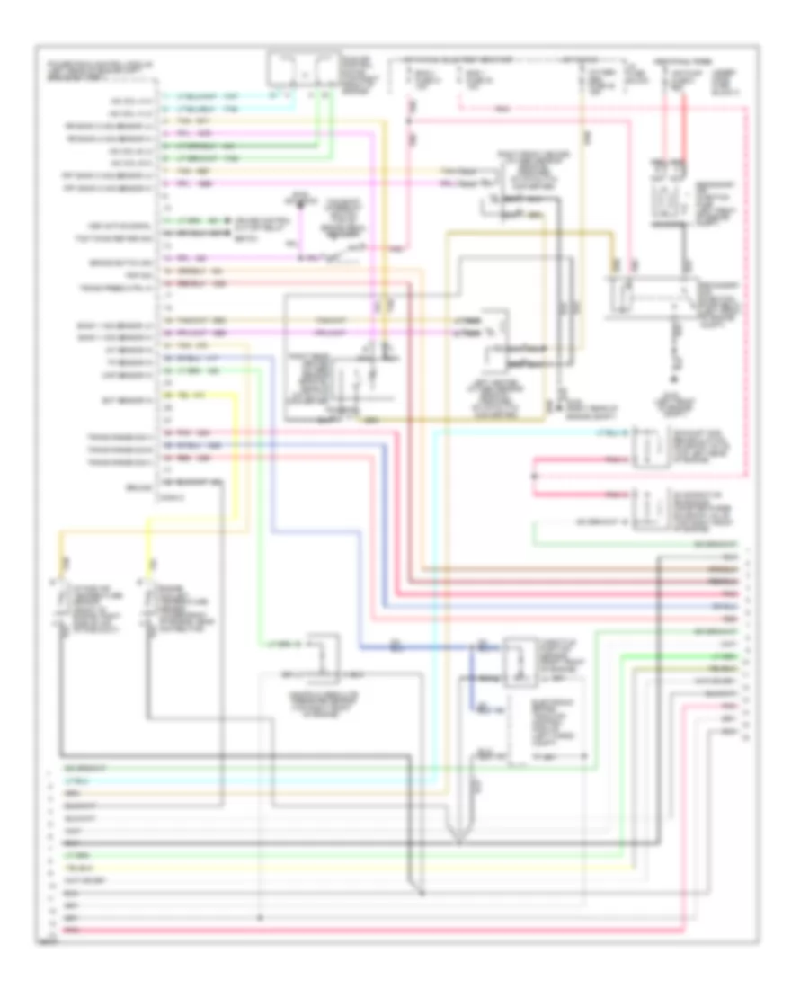
5.7L (VIN P), Engine Performance Wiring Diagrams (1 of 3) for Chevrolet Corvette ZR-1 1995
 https://portal-diagnostov.com/license.html
Automotive Electricians Portal FZCO
Automotive Electricians Portal FZCO
https://portal-diagnostov.com/license.html
https://portal-diagnostov.com/license.html
Automotive Electricians Portal FZCO
Automotive Electricians Portal FZCO
List of elements for 5.7L (VIN P), Engine Performance Wiring Diagrams (1 of 3) for Chevrolet Corvette ZR-1 1995:
- (below throttle body)
- (left rear of engine)
- (m/t) 2&3 block ctrl
- 324 (m/t)
- 5 volt ref
- 687 (a/t)
- A/c clutch status
- A/c request sig
- Air conditioning
- Air conditioning compressor
- Air pump relay ctrl
- Battery
- Coil wire
- Conn a
- Conn b
- Control module (m/t)
- Coolant fan relays
- Cruise active signal
- Cruise control module
- Cruise control, speedo, radio, cent ctrl module
- Dist ignition feed
- Dist ref low sig
- Distributor
- E.c.m. fuse 33 5a
- Egr solenoid ctrl
- Eng 1 fuse 30 10a
- Fuel injector #1
- Fuel injector #2
- Fuel injector #3
- Fuel injector #4
- Fuel injector #5
- Fuel injector #6
- Fuel injector #7
- Fuel injector #8
- Fuel pump relay ctrl
- G114
- G114 (left rear of engine)
- Ground
- Hi res signal
- High resolution sig
- Hot at all times
- Hot in run, bulb test or start
- I/p fuse block
- Ign voltage
- Ignition
- Ignition coil
- Ignition ctrl
- Inj # 8 ctrl
- Inj #1 ctrl
- Inj #2 ctrl
- Inj #3 ctrl
- Inj #4 ctrl
- Inj #5 ctrl
- Inj #6 ctrl
- Inj #7 ctrl
- Inj 1 fuse 22 10a
- Inj 2 fuse 23 10a
- Low res signal
- Low resolution sig
- Maf sensor in
- Mass air flow sensor (front of engine, in air intake duct)
- Optical sensor
- Pcm fuse 1 20a
- Pnk
- Pnk c
- Powertrain control module (left rear of engine cmpt, above battery)
- Pri cool fan relay ctrl
- Red
- Ref low
- Sec cool fan relay ctrl
- Selective ride
- Sensor ground
- Solid state
- Spark plugs
- Tach output
- Tachometer, electronic brake/ traction control module
- Trans 1-2 shift ctrl
- Trans 2-3 shift ctrl
- Trans 3-2 shift ctrl
- Under- hood fuse block 1
- Vehicle speed sensor (left rear of transmission)
- Vss ground
- Vss out
- Vss signal
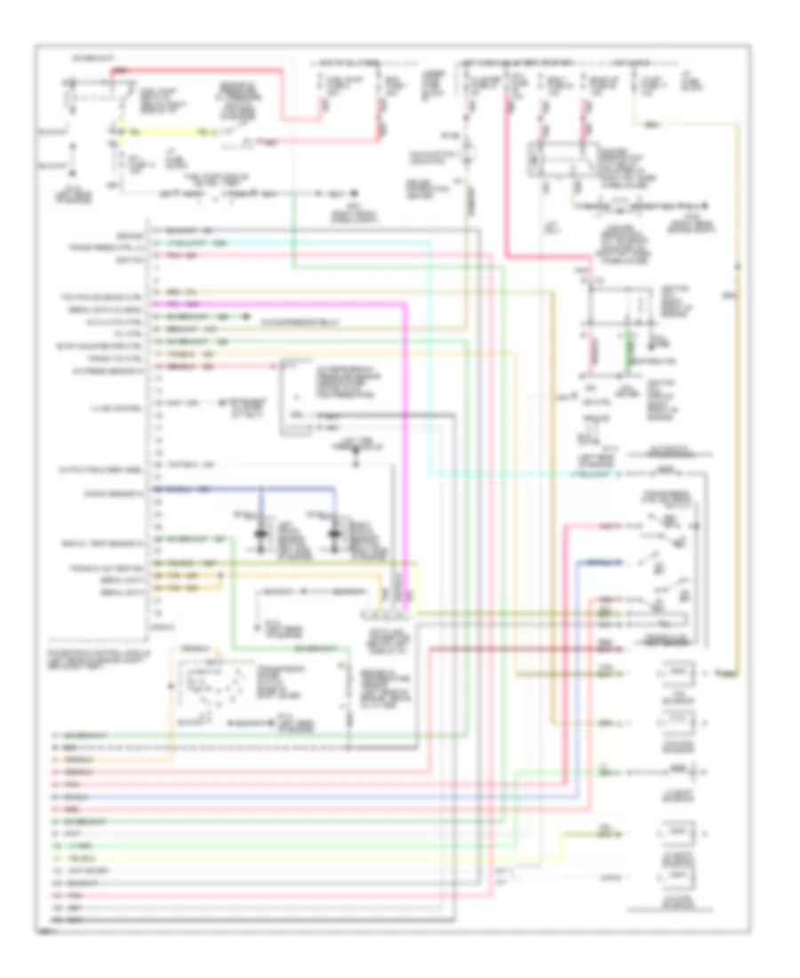
5.7L (VIN P), Engine Performance Wiring Diagrams (2 of 3) for Chevrolet Corvette ZR-1 1995
List of elements for 5.7L (VIN P), Engine Performance Wiring Diagrams (2 of 3) for Chevrolet Corvette ZR-1 1995:
- (left front of engine compt)
- Air pump fuse 8 20a
- Asr active signal
- Bank 1 h02 sensor lo
- Bank 1 ho2 sensor hi
- Brake switch sig
- Btsi solenoid
- Conn c
- Cruise control cut-off relay
- Ebtcm
- Ect sensor in
- Electronic brake/ traction control module (left cargo compt)
- Eng 1 fuse 30 10a
- Eng 2 fuse 21 10a
- Engine coolant temperature sensor (lower front of engine, near distributor)
- Evaporative emissions canister purge solenoid valve (top right front of engine)
- Exhaust gas recirculation solenoid valve (top left rear of engine)
- Frt bank 2 ho2 sensor hi
- Frt bank 2 ho2 sensor lo
- G100
- G105 (right rear of engine compt)
- Ground
- Hot at all times
- Hot in run
- Hot in run, bulb test or start
- I/p fuse block
- Iac coil a hi
- Iac coil a lo
- Iac coil b hi
- Iac coil b lo
- Iat sensor in
- Idle air control motor (top right front of engine)
- Intake air temperature sensor (front of engine, right side of air intake duct)
- Left heated oxygen sensor (bank #1, forward of catalytic converter)
- Manifold absolute pressure sensor (top right front
- Map sensor in
- Nca
- Of engine)
- Oxygen sen fuse 20 15a
- Pnk
- Pnp sig
- Powertrain control module (left rear of engine cmpt, above battery)
- Red
- Right front heated oxygen sensor (bank #2, forward of catalytic converter)
- Right rear heated oxygen sensor (bank #2, rear of catalytic converter)
- Rr bank 2 ho2 sensor hi
- Rr bank 2 ho2 sensor lo
- Secondary air injection pump (left front of engine compt)
- Secondary air injection pump relay (left front of engine compt)
- Solenoid
- Tan
- Tan b
- Tcc/shift interrupt switch (top of brake pedal bracket)
- Tcs timing retard sig
- Throttle position sensor (right front of engine)
- Tp sensor in
- Trans press ctrl hi
- Trans range sig a
- Trans range sig b
- Trans range sig c
- Under- hood fuse block 2
5.7L (VIN P), Engine Performance Wiring Diagrams (3 of 3) for Chevrolet Corvette ZR-1 1995
List of elements for 5.7L (VIN P), Engine Performance Wiring Diagrams (3 of 3) for Chevrolet Corvette ZR-1 1995:
- (below left side of i/p)
- (left rear of engine)
- (right front cargo compt)
- (right rear engine compt)
- 1-2 shift solenoid
- 1-4 ind control
- 2-3 shift solenoid
- 2nd/3rd
- 2nd/3rd gear block- out relay (mounted on right frt inner wheelhouse)
- 3-2 ctrl solenoid
- A/c clutch ctrl
- A/c compressor relay
- A/c press sensor in
- A/c refrigerant pressure sensor (near blower motor, in a/c high press pipe)
- A/t
- Automatic transmission
- B7,b8
- Back-up fuse 28 15a
- C red
- Cluster fuse 27 5a
- Coil driver
- Coil fuse 10a
- Coil wire
- Conn d
- D2 sw
- D3 sw
- D4 sw
- Data link connector
- Distributor
- Driver information center
- Ecm fuse 1 20a
- Eng 1 fuse 30 10a
- Eng oil temp sensor in
- Engine oil pressure/ oil pressure switch (top rear of engine)
- Engine oil temperature sensor (left rear of engine, above oil filter)
- Evap canister prg ctrl
- Fp 1 fuse 14 10a
- Fuel pump fuse 2 20a
- Fuel pump module (in fuel tank)
- Fuel pump relay #1 (below right side of i/p)
- G105
- G114
- G114 (left rear of engine)
- G401
- Gear block- out solenoid (mounted on
- Ground
- Hot at all times
- Hot in run
- Hot in run, bulb test or start
- I/p fuse block
- Ign
- Ign ctrl
- Ignition
- Ignition coil (right front of engine)
- Ignition coil module (right front of engine)
- Instrument cluster (m/t only)
- Knock sensor in
- Left knock sensor (bottom left side of engine)
- Lo sw
- Low tire
- M/t
- M/t only
- Malfunction indicator
- Mil ctrl
- Nca
- Output/field serv enbl
- Pnk
- Powertrain control module (left rear of engine compt, above battery)
- Press module
- Red
- Rev sw
- Right frt inner
- Right knock sensor (bottom right side of engine)
- Serial data
- Serial data (class 2)
- Tan
- Tcc pwm solenoid
- Tcc pwm solenoid ctrl
- Tcc solenoid
- Trans fluid temp sensor
- Trans fluid temp sig
- Trans press ctrl lo
- Trans press ctrl solenoid
- Trans tcc ctrl
- Transmission range switch (base of shift lever)
- Under- hood fuse block #1
- Valet fuse 17 10a
- Wheelhouse)

 Čeština
 Dansk
Dansk Deutsch
 Ελληνικά
 English
 English
 Español
 Suomi
Suomi Français
 Français
 עברית
עברית Hrvatski
 Magyar
 Italiano
 日本語
日本語 한국어
한국어 Nederlands
 Polski
 Português
 Română
 Русский
 Slovenčina
 Slovenščina
 Svenska
 Türkçe
 中文 (中国)