POWER DISTRIBUTION
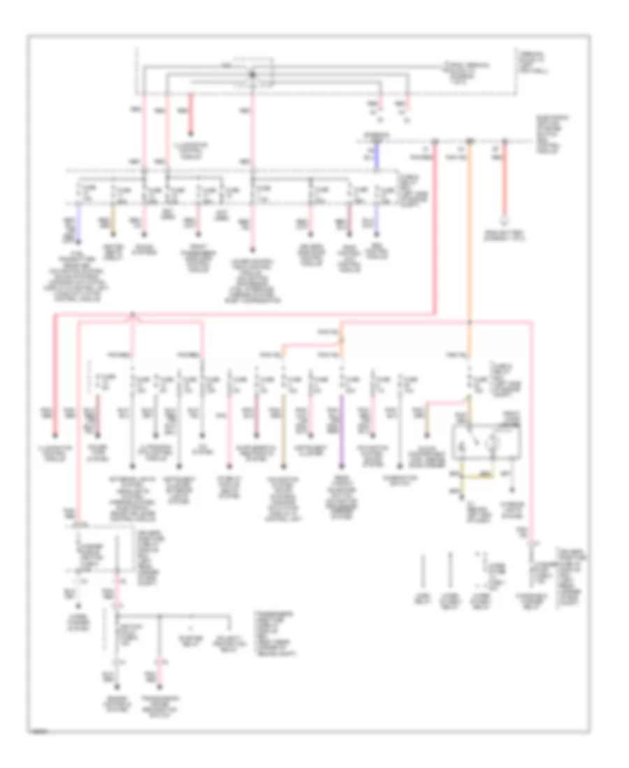
Power Distribution Wiring Diagram, Convertible (1 of 2) for Mercedes-Benz CLK320 2003
 https://portal-diagnostov.com/license.html
Automotive Electricians Portal FZCO
Automotive Electricians Portal FZCO
https://portal-diagnostov.com/license.html
https://portal-diagnostov.com/license.html
Automotive Electricians Portal FZCO
Automotive Electricians Portal FZCO
List of elements for Power Distribution Wiring Diagram, Convertible (1 of 2) for Mercedes-Benz CLK320 2003:
- 2.1
- 3.2
- A/c system
- Air pump relay module, asr/ets/esp hydraulic unit
- Battery
- Circuit 30z fuse 7.5a
- Control module box
- Data link connectors (obd ii, dtc readout)
- Driver's side fuse & relay module box (left rear of eng compt)
- Engine control module
- Esp/bas control module
- Fuel pump relay module
- Fuse & relay box (left side of engine compt)
- Fuse 10a
- Fuse 15a
- Fuse 25a
- Fuse 30a
- Fuse 30a (or 60a)
- Fuse 40a
- Fuse 5a
- Generator, starter, esp/bas control module
- Hcs pump fuse 3 30a
- Hcs pump relay
- High pressure/ return pump relay
- Horn relay
- Horns fuse 4 10a
- Instrument cluster
- Interior lights system, anti- theft system
- Interior lights system, passenger's side door control module, ctel transmitter/ receiver, tele-aid control module
- Nca
- Oil cooler fan relay
- Passenger's side fuse & relay module box (right rear corner of engine compt)
- Polarity protection relay
- Power tops system
- Pse control module
- Rear fuse box
- Red
- Red/ pnk
- Reserve fuse 7 30a
- Roof control unit control module
- Sam fuse 5 15a
- Seats system
- Signal pick-up & activation module
- Starter
- Steering angle sensor
- Terminal block x12/3 (left rear of engine compt)
- Terminal block x4 (left footwell)
- To electronic ignition- starter switch control module (diagram 2 of 2)
- To terminal block x4 (diagram 2 of 2)
- W/ cabriolet
- W10 (right rear of trunk)
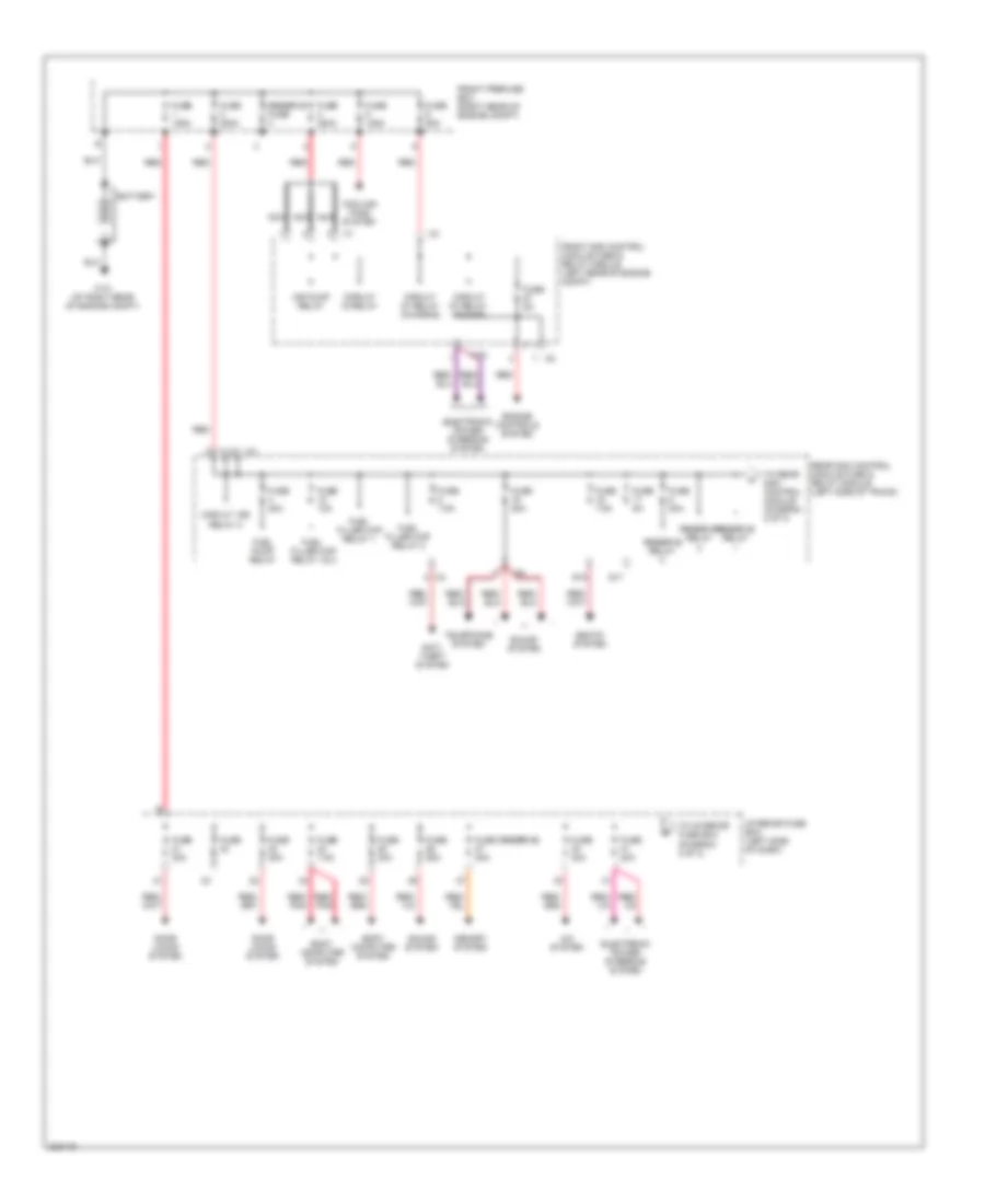
Power Distribution Wiring Diagram, Convertible (2 of 2) for Mercedes-Benz CLK320 2003
List of elements for Power Distribution Wiring Diagram, Convertible (2 of 2) for Mercedes-Benz CLK320 2003:
- (not used)
- 15r
- 2.2
- A/c system
- Cf relay module, seats system
- Combination switch
- Ctel transmitter/ receiver, navigation system, sound systems, command activation display & control unit, voice activation control module
- Driver's side door control module
- Driver's side fuse & relay module box (left rear corner of eng compt)
- Electronic ignition- starter switch (eis) control module
- Engine controls system
- Esc control module
- Exterior lights system, headlights system, mirrors system, electronic selector lever control module
- From battery (diagram 1 of 2)
- From terminal block x4 (diagram 1 of 2)
- Front cigar lighter
- Front passenger's side door control module
- Fuse
- Fuse & relay box (left side of engine compt)
- Fuse 10a
- Fuse 15a
- Fuse 20a
- Fuse 25a
- Fuse 2o 15a
- Fuse 30a
- Fuse 5a
- Fuse 7.5
- Fuse 7.5a
- Glove compartment lamp, garage door opener
- Heated seats circuit
- Horn relay
- Ignition coils fuse 6 15a
- Illumination control module
- Instrument cluster
- Instrument cluster, exterior lights system
- Interior lights system
- Lower control field control
- Module,
- Navigation processor, ctel interface, mirrors system, e-net compensator
- Navigation system, sound system
- Navigation system, sound systems, command activation display & control unit
- Passenger's side fuse & relay module box (right rear corner of engine compt)
- Pnk
- Pnk/ red
- Pnk/red
- Polarity protection relay
- Power tops system
- Rear window sunshade switch, navigation processor, mirrors system
- Red
- Roof control unit control module
- Sound systems
- Starter relay
- Steering lock
- Terminal block x4 (left footwell)
- Transmission range recognition switch
- Ultrasonic pts control module
- W1 (behind left end of dash)
- Washer nozzle heating fuse 6 7.5a
- Washer pump fuse 2 7.5a
- Windshield washer relay
- Wiper stage 1 relay
- Wiper stage 1-2 fuse 1 40a
- Wiper stage 2 relay
- Wiper/ washer system
Power Distribution Wiring Diagram, Except Convertible (1 of 3) for Mercedes-Benz CLK320 2003
List of elements for Power Distribution Wiring Diagram, Except Convertible (1 of 3) for Mercedes-Benz CLK320 2003:
- A/c system
- Air pump relay
- Anti- theft system
- Battery
- Body computer system
- C19
- Circuit 15 relay
- Circuit 15r relay 2
- Circuit 87 relay (chassis)
- Circuit 87 relay (engine)
- Cooling fans system
- Door locks system
- Electronic power steering system
- Engine controls system
- Front prefuse box (right rear of engine compt)
- Front sam control module fuse & relay module (left rear of engine compt)
- Fuel filler cap relay 1& 2
- Fuel filler cap relay 1
- Fuel filler cap relay 2
- Fuel pump relay
- Fuse
- Fuse (reserve) 30a
- Fuse 10a
- Fuse 125a
- Fuse 200a
- Fuse 20a
- Fuse 25a
- Fuse 30a
- Fuse 40a
- Fuse 5a
- Fuse 60a
- Fuse 7.5a
- Interior fuse box (left side of dash)
- Memory system
- Nca
- Rear sam control module fuse & relay module (left side of trunk)
- Red
- Red/ pnk
- Reserve fuse
- Reserve relay
- S17
- S19
- Seats system
- Sound system
- Telephone system
- To interior fuse box (diagram 2 of 3)
- To rear sam control module (diagram 2 of 3)
- W10 (at right rear of engine compt)
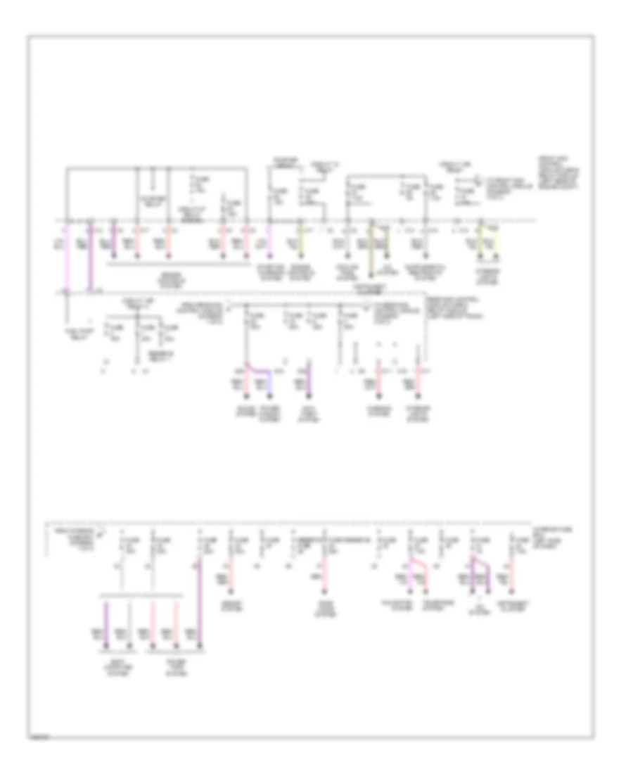
Power Distribution Wiring Diagram, Except Convertible (2 of 3) for Mercedes-Benz CLK320 2003
List of elements for Power Distribution Wiring Diagram, Except Convertible (2 of 3) for Mercedes-Benz CLK320 2003:
- A/c system
- Anti- theft system
- Body computer system
- C12
- C13
- C14
- C16
- C17
- C19
- C28
- Circuit 15 relay
- Circuit 15r relay
- Circuit 15r relay 2
- Circuit 87 relay (engine)
- Cooling fans system
- Door locks system
- Engine controls system
- From interior b fuse box (diagram 1 of 3)
- From rear sam a control module (diagram 1 of 3)
- Front sam control module fuse & relay module (left rear of engine compt)
- Fuel pump relay
- Fuse
- Fuse (reserve) 25a
- Fuse 15a
- Fuse 20a
- Fuse 25a
- Fuse 30a
- Fuse 5a
- Fuse 7.5a
- Instrument cluster
- Interior fuse box (left side of dash)
- Interior lights system
- Memory system
- Navigation system
- Power tops system
- Power window system
- Rear sam control module fuse & relay module (left side of trunk)
- Red
- Reserve fuse
- Reserve relay 1
- S18
- S20
- Sound system
- Starter relay
- Starting/ charging system
- Telephone system
- To front sam control module (diagram 3 of 3)
- To rear sam control module (diagram 3 of 3)
- Warning system
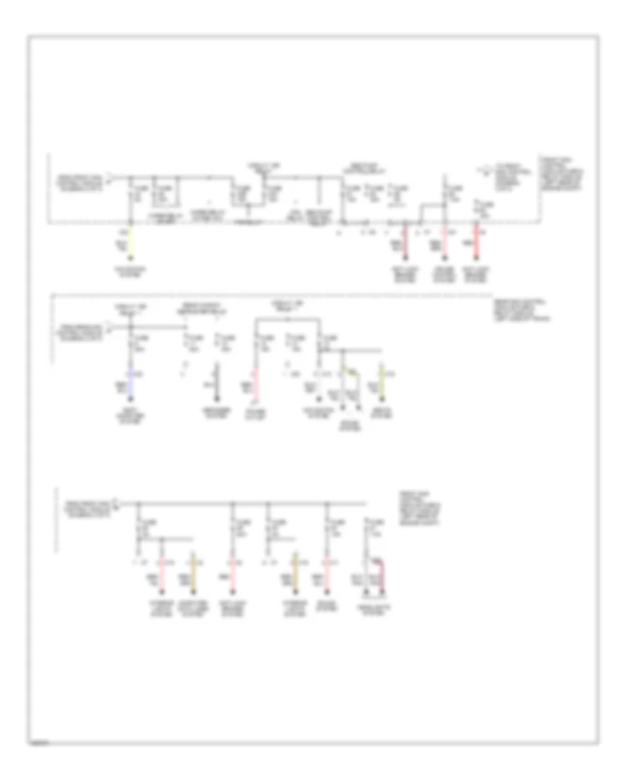
Power Distribution Wiring Diagram, Except Convertible (3 of 3) for Mercedes-Benz CLK320 2003
List of elements for Power Distribution Wiring Diagram, Except Convertible (3 of 3) for Mercedes-Benz CLK320 2003:
- Anti-lock brakes system
- Body computer system
- C11
- C12
- C19
- C20
- C21
- C22
- C23
- C24
- Circuit 15r relay
- Circuit 15r relay 1
- Computer data lines system
- Cruise control system
- Defogger system
- Fan relay
- From front sam c control module (diagram 2 of 3)
- From front sam e control module (diagram 3 of 3)
- From rear sam d control module (diagram 2 of 3)
- Front sam control module fuse & relay module (left rear of engine compt)
- Fuse 15a
- Fuse 20a
- Fuse 25a
- Fuse 40a
- Fuse 43a 15a
- Fuse 43b 15a
- Fuse 50a
- Fuse 5a
- Fuse 7.5a
- Headlights system
- Interior lights system
- Navigation system
- Power outlet
- Rear sam control module fuse & relay module (left side of trunk)
- Rear window defroster relay
- Red
- Seats system
- Seq pump control relay
- Sound system
- To front sam control module (diagram 3 of 3)
- Wiper relay on/off
- Wiper relay stage 1& 2

 Čeština
 Dansk
Dansk Deutsch
 Ελληνικά
 English
 English
 Español
 Suomi
Suomi Français
 Français
 עברית
עברית Hrvatski
 Magyar
 Italiano
 日本語
日本語 한국어
한국어 Nederlands
 Polski
 Português
 Română
 Русский
 Slovenčina
 Slovenščina
 Svenska
 Türkçe
 中文 (中国)