TRANSMISSION
3.4L
3.4L, 4WD Wiring Diagram for Toyota Tundra Limited 2000
 https://portal-diagnostov.com/license.html
Automotive Electricians Portal FZCO
Automotive Electricians Portal FZCO
https://portal-diagnostov.com/license.html
https://portal-diagnostov.com/license.html
Automotive Electricians Portal FZCO
Automotive Electricians Portal FZCO
List of elements for 3.4L, 4WD Wiring Diagram for Toyota Tundra Limited 2000:
- (behind right side of dash) j/c 12
- 4wd
- 4wd fuse 20a
- 4wd ind
- A/t p ind
- Abs actuator with ecu (right rear of engine compt)
- Acc fuse 15a
- Add actuator (left side of trans)
- C11
- C14
- California
- California with a/t
- Combination meter
- Detection switch (4wd position) (transfer case)
- Detection switch (l4 position) (transfer case)
- Detection switch (neutral position) (transfer case)
- Didoe (a/t) (behind center of dash)
- Driver side j/b (lower left side of dash)
- Engine control module (behind right side of dash)
- Ex1
- Ex13
- Except california
- Except california with a/t
- G11
- G203
- Gauge fuse 10a
- Hot in on or acc
- Hot in on or start
- J/c 10 (behind center of dash)
- J/c 13 (right kick panel)
- J/c 6 (behind center of dash)
- J/c 8 (behind center of dash)
- J/c 9 (behind center of dash)
- Neutral position switch (part of park/ neutral position switch)
- Red
- Tfn
- Transmission control relay (at right kick panel)
- W/ abs
- W/ power mirrors
- W/o abs
- W/o power mirrors
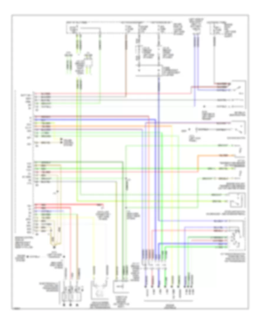
3.4L, A/T Wiring Diagram, California for Toyota Tundra Limited 2000
List of elements for 3.4L, A/T Wiring Diagram, California for Toyota Tundra Limited 2000:
- (left side of eng compt, next to battery) j/c j1
- 2 ind
- A/t indicator switch (park/neutral position switch) (on transmission)
- A/t oil temperature sensor (on transmission)
- Acc fuse 15a
- Batt (b+)
- Cruise control system
- D ind
- Data link connector 1 (left side of eng)
- Diode (upper right of instrument cluster)
- Driver side j/b (lower left side of dash)
- E01
- E05
- E1 (grd)
- Efi 1 fuse 15a
- Efi relay (eng room r/b)
- Electronically controlled transmission solenoids
- Engine control module (behind right side of dash, near "a" pillar)
- Engine controls
- Engine coolant temperature sensor (on top center of eng)
- Engine room r/b (left side of eng compt)
- Eo2
- Eo3
- F11
- G100 (center of left front fender)
- G11
- G131 (left intake manifold)
- G200
- Gauge fuse 10a
- Hot at all times
- Hot in acc or on
- Hot in on or start
- I13
- I13 (eng harn, right rear of eng)
- I14
- I7 (eng harn, right rear of eng)
- Idl0
- Ign fuse 5a
- Igsw
- J/c 3 (left kick panel)
- J/c j11 (behind upper right side of dash, near air bag)
- J/c j12 (behind upper right side of dash)
- J/c j8 (behind upper left side of dash)
- J/c j9 (behind upper left side of dash)
- L ind
- Mrel
- N ind
- No. 1
- No. 2
- No. 3
- O/d main switch
- Od off
- Od1
- Od2
- Oil
- Oil temp
- Oil-w
- P ind
- R ind
- Red
- Sp1
- Sp2+
- Sp2-
- Speedo
- Stop fuse 15a
- Stoplamp switch (on bracket, above brake pedal)
- Te1
- Throttle position sensor (on throttle body)
- Thw
- Vcc
- Vehicle speed sensor (for ect) (on transmission)
- Vta
- W/ cruise
- W/o cruise
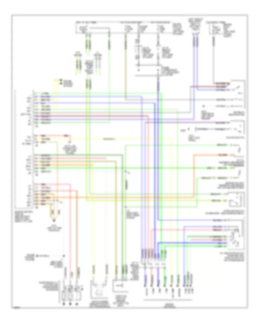
3.4L, A/T Wiring Diagram, Except California for Toyota Tundra Limited 2000
List of elements for 3.4L, A/T Wiring Diagram, Except California for Toyota Tundra Limited 2000:
- (4wd only)
- (left side of eng compt, next to battery) j/c j1
- 2 ind
- A/t indicator switch (park/neutral position switch) (on transmission)
- A/t oil temperature sensor (on transmission)
- Acc fuse 15a
- Batt (b+)
- Cruise control system
- D ind
- Data link connector 1 (left side of eng)
- Diode (upper right of instrument cluster)
- Driver side j/b (lower left side of dash)
- E01
- E1 (grd)
- Efi 1 fuse 15a
- Efi relay (eng room r/b)
- Electronically controlled transmission solenoids
- Engine control module (behind right side of dash, near "a" pillar)
- Engine controls
- Engine coolant temperature sensor (on top center of eng)
- Engine room r/b (left side of eng compt)
- Eo2
- Eo3
- F11
- G100 (center of left front fender)
- G11
- G131 (left intake manifold)
- G200
- Gauge fuse 10a
- Hot at all times
- Hot in acc or on
- Hot in on or start
- I13
- I13 (eng harn, right rear of eng)
- I14
- I7 (eng harn, right rear of eng)
- Idl0
- Ign fuse 5a
- J/c 3 (left kick panel)
- J/c j11 (behind upper right side of dash, near air bag)
- J/c j12 (behind upper right side of dash)
- J/c j8 (behind upper left side of dash)
- J/c j9 (behind upper left side of dash)
- L ind
- N ind
- No. 1
- No. 2
- No. 3
- O/d main switch
- Od off
- Od1
- Od2
- Oil
- Oil temp
- Oil-w
- P ind
- R ind
- Red
- Sp1
- Sp2+
- Sp2-
- Speedo
- Stop fuse 15a
- Stoplamp switch (on bracket, above brake pedal)
- Te1
- Throttle position sensor (on throttle body)
- Thw
- Vehicle speed sensor (for ect) (on transmission)
- Vta
- W/ cruise
- W/o cruise
4.7L
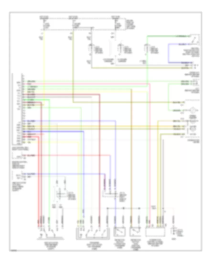
4.7L, 4WD Wiring Diagram for Toyota Tundra Limited 2000
List of elements for 4.7L, 4WD Wiring Diagram for Toyota Tundra Limited 2000:
- (behind center of dash)
- (behind right side of dash)
- 2-4
- 4hi ind
- 4lo ind
- 4wd
- 4wd control ecu (right kick panel)
- 4wd fuse 20a
- Abs actuator with ecu (right rear of engine compt)
- Acc fuse 15a
- Add
- Add actuator (center rear of engine compt)
- C11
- C12
- C13
- Combination meter
- Detection switch (4wd positon) (transfer case)
- Detection switch (l4 position) (transfer case)
- Didoe (a/t) (behind center of dash)
- Dl1
- Dl2
- Dm1
- Dm2
- Driver side j/b (lower left side of dash)
- Engine control module (behind right side of dash)
- Ex1
- Ex13
- G11
- G203
- Gauge fuse 10a
- Gnd
- H-l
- Hot in on or acc
- Hot in on or start
- I24
- Ind1
- Ind2
- Integration control & panel (behind center of dash)
- J/c 10
- J/c 12
- J/c 13 (right kick panel)
- J/c 6 (behind center of dash)
- J/c 7 (behind center of dash)
- J/c 8 (behind center of dash)
- J/c 9 (behind center of dash)
- Neutral position switch (part of park/ neutral position switch)
- Pnk
- Red
- Spd
- Speed- ometer
- Tl1
- Tl2
- Tl3
- Tm1
- Tm2
- Transfer shift actuator (on transfer case)
- W/ abs
- W/ power mirrors
- W/o abs
- W/o power mirrors
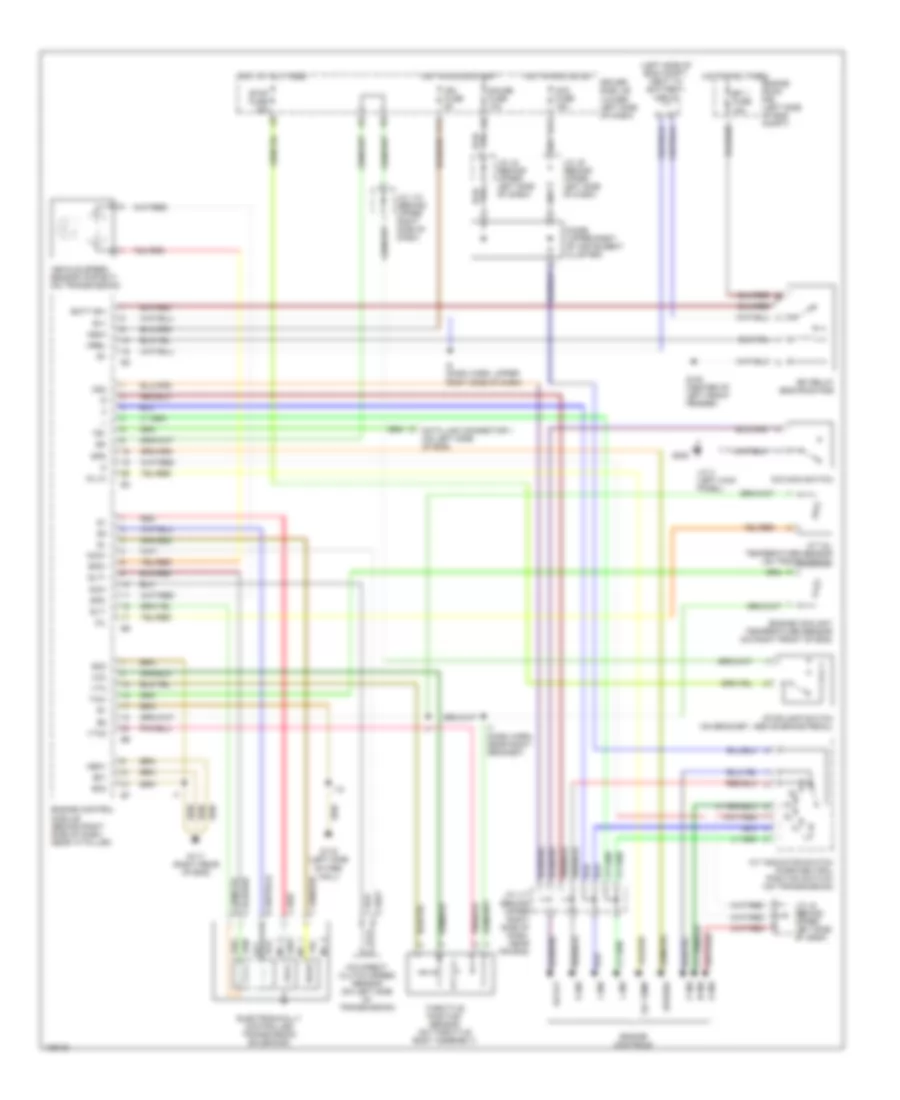
4.7L, A/T Wiring Diagram for Toyota Tundra Limited 2000
List of elements for 4.7L, A/T Wiring Diagram for Toyota Tundra Limited 2000:
- (left side of eng compt, next to battery) j/c j1
- 2 ind
- A/t indicator switch (park/neutral position switch) (on transmission)
- A/t oil temperature sensor (on transmission)
- Acc fuse 15a
- B+1
- Batt (b+)
- D ind
- Data link connector 1 (on left side of eng)
- Diode (upper right of instrument cluster)
- Driver side j/b (lower left side of dash)
- E01
- Efi 1 fuse 15a
- Efi relay (eng room r/b)
- Electronically controlled transmission solenoids
- Engine control module (behind right side of dash, near "a" pillar)
- Engine controls
- Engine coolant temperature sensor (on right front of eng)
- Engine room r/b (left side of eng compt)
- Eo2
- Eo3
- F11
- G100 (center of left front fender)
- G11
- G116 (left side of fire- wall)
- G117 (right rear of eng)
- G200
- Gauge fuse 10a
- Hot at all times
- Hot in acc or on
- Hot in on or start
- I10
- I5 (dash harn, upper right side of dash)
- I7 (dash harn, near right grommet)
- Ign fuse 5a
- Igsw
- J/c 3 (left kick panel)
- J/c j11 (behind upper right side of dash, near air bag)
- J/c j12 (behind upper right side of dash)
- J/c j8 (behind upper left side of dash)
- J/c j9 (behind upper left side of dash)
- L ind
- Meo1
- Mrel
- N ind
- Nco+
- Nco-
- No. 1
- No. 2
- No. 3
- O/d direct clutch speed sensor (on left side of transmission)
- O/d main switch
- Od off
- Od2
- Oil
- Oil temp
- Oil-w
- P ind
- R ind
- Red
- Slt
- Slt+
- Slt-
- Sp2+
- Sp2-
- Spd
- Speedo
- Stop fuse 15a
- Stoplamp switch (on bracket, above brake pedal)
- Te1
- Throttle position sensor (on throttle body assembly)
- Thw
- Vcc
- Vehicle speed sensor (for ect) (on transmission)
- Vta
- Vta2

 Čeština
 Dansk
Dansk Deutsch
 Ελληνικά
 English
 English
 Español
 Suomi
Suomi Français
 Français
 עברית
עברית Hrvatski
 Magyar
 Italiano
 日本語
日本語 한국어
한국어 Nederlands
 Polski
 Português
 Română
 Русский
 Slovenčina
 Slovenščina
 Svenska
 Türkçe
 中文 (中国)