
 Čeština
 Dansk
Dansk Deutsch
 Ελληνικά
 English
 English
 Español
 Suomi
Suomi Français
 Français
 עברית
עברית Hrvatski
 Magyar
 Italiano
 日本語
日本語 한국어
한국어 Nederlands
 Polski
 Português
 Română
 Русский
 Slovenčina
 Slovenščina
 Svenska
 Türkçe
 中文 (中国)

Audi A6 1998 - 1998 ELECTRICAL Fuses & Circuit Breakers - A6 & A6 Quattro
Audi A6 1998 - FUSES FUSE COLOR IDENTIFICATION
Audi A6 1998 FUSE COLOR/AMP RATING
Fuse Color Amp Rating Blue 15 Brown 7.5 Green 30 Light Brown 5 Red 10 Transparent (White) 25 Yellow 20
Audi A6 1998 - FUSE PANEL LOCATION
Fuse panel is located behind left side of dashboard. See Fig. 1.


Fig. 1: Audi A6 1998 - Component Locations - Locating Fuse Panel
Audi A6 1998 - FUSE PANEL IDENTIFICATION
For fuse position within panel, see Fig. 2. For fuse number, amperage rating and circuits protected, see FUSE IDENTIFICATION (FUSE PANEL) table.
Fig. 2: Audi A6 1998 - Component Locations - Identifying Fuse Panel Fuses

NOTE: Fuses 23 through 44 may be designated in wiring diagrams with a prefix of 2. For example, fuse No. 29 may be labeled as 229. Fuse No. 43 may be labeled as 243.
Audi A6 1998 FUSE IDENTIFICATION (FUSE PANEL)
Fuse No. Amp Rating Circuits Protected 1 5 Washer Nozzle Heaters 2 10 Emergency Flasher Switch & Relay 3 5 Glove Compartment Light, Selector Lever Light Relay Protection Diode 4 5 License Plate Light 5 5 Outside Temperature Display, Transmission Range Selector Lever Display, Lamp Control Module, A/C Control Head, Air Quality Sensor, Mirror Adjustment, Mirror Fold-Away Function Control Module, Rear Window Shade, Radio 6 5 Central Locking Control Module 7 10 ABS Control Module, Anti-Slip Control Switch 8 5 Telephone Transceiver 9 10 Heated Outside Mirrors, Mirror Memory switch 10 (1) 5 Headlight Beam Adjustment Motors, Beam Adjustment Control Module 11 N/A Not Used 12 10 DLC 13 10 Brake Light Switch 14 10 Memory Program Switch, Central Locking Control Module, Door Warning Lights, Passenger Compartment Monitoring Switch, Trunk Lid Release Switch 15 10 Instrument Cluster, Solar Cell Separation Relay, Transmission Control Module, Selector Lever Light Relay, Mirror Memory Control Module 16 N/A Not Used 17 N/A Not Used 18 10 High Beam (Right), Headlight High Beam Indicator Light 19 10 High Beam (Left), Fog Light 20 10 Lamp Control Module, Headlight Beam Adjusting Motor (Right) (2) 21 10 Lamp Control Module, Headlight Beam Adjuster (Left) (2) 22 5 Lamp Control Module, Parking Light (Right) 23 5 Lamp Control Module, Parking Light (Left) 24 25 Wiper/Washer Intermittent Relay 25 30 Fresh Air Blower, Solar Cell Separation Relay, A/C Pressured Switch, A/C Control Head, A/C Clutch Relay, Ultra-Sound Sensor Control Module, Solar Operation Control Module 26 30 A/C Control Head, Rear Window Defogger Switch 27 15 Rear Window Wiper Motor, Heated Steering Wheel 28 20 Fuel Pump 29 20 Leak Detection Pump, Lambda-Probe Heaters, Camshaft Adjustment (Valve 1), Intake Manifold Change-Over Valve, Oxygen Sensor Heaters, Secondary Air Injector Solenoid Valve & Pump Relay 30 20 Power Sunroof Control Module 31 15 Multi-Function Transmission Range Switch, MAF Sensor, DLC, ECM, Automatic Day/Night Interior Mirror, Shift Lock Solenoid, Tiptronic Switch 32 20 ECM, Ignition Coils 33 15 Cigarette Lighter 34 15 Fuel Injectors 35 N/A Not Used 36 15 Fog Light Switch 37 20 Radio, Right Rear Woofer/Amp, Power Antenna, Telephone Transceiver 38 15 Central Locking Control Module, Ultra-Sound Sensor Control Module 39 15 Emergency Flasher Switch 40 25 Dual Horn Relay 41 N/A Not Used 42 N/A Not Used 43 N/A Not Used 44 30 Heated Seat Adjuster
(1) Applies to vehicles equipped with high intensity gas discharge lamps only.
(2) Applies to vehicles not equipped with high intensity gas discharge lamps.
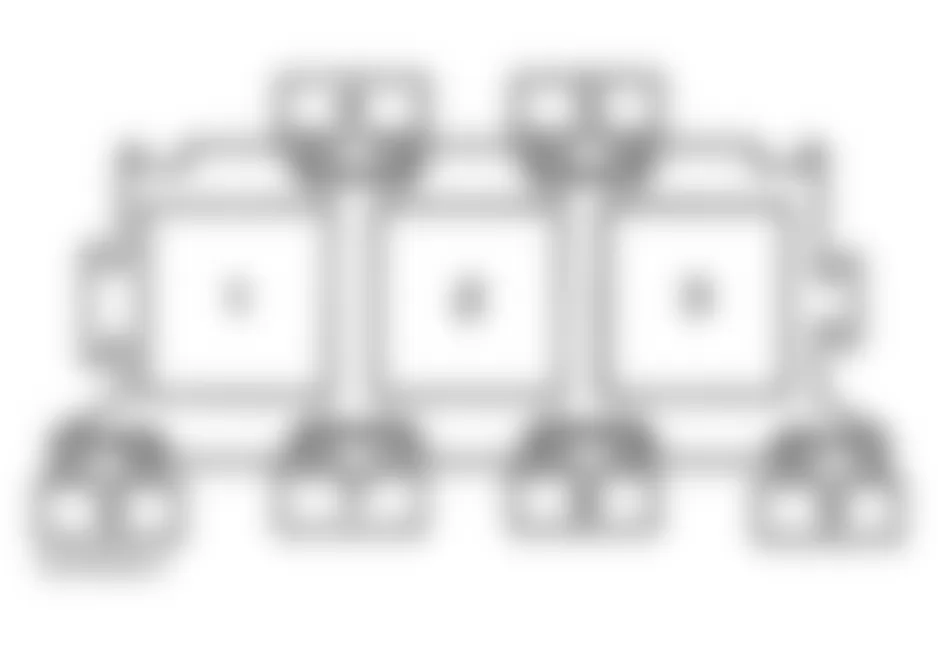
Audi A6 1998 - RELAYS THREE FOLD RELAY PANEL (E-BOX)
For fuse and relay positions within carrier, see Fig. 3. For relay number, position number and circuits protected, see RELAY IDENTIFICATION (THREE FOLD RELAY PANEL) table.
NOTE: Three fold relay panel is located in electronics box, plenum chamber, in the left, rear corner of engine compartment.
NOTE: Manufacturer does not provide fuse number, amperage rating, or circuits protected for three fold relay panel fuses.
Fig. 3: Audi A6 1998 - Component Locations - Identifying Three Fold Relay Panel Components
Audi A6 1998 RELAY IDENTIFICATION (THREE FOLD RELAY PANEL)
Position Relay No. Circuit Protected 1 N/A Not Used 2 J299 Secondary Air Injection Pump relay 3 N/A Not Used
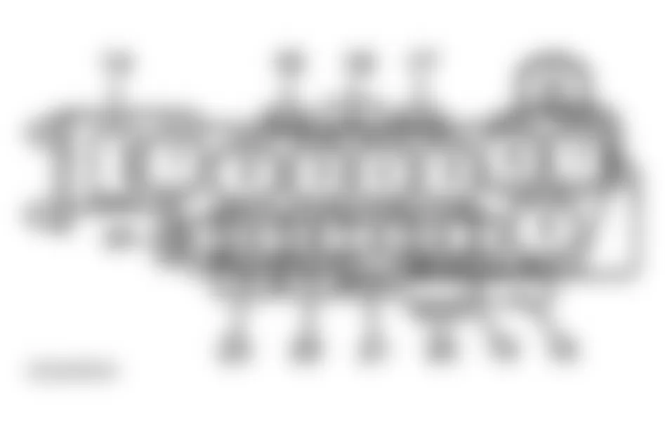
Audi A6 1998 - EIGHT FOLD RELAY PANEL
NOTE: Eight fold relay panel may also be referred to as auxiliary relay panel.
For fuse and relay positions within panel, see Fig. 4. For relay number, position number and circuits protected, see RELAY IDENTIFICATION (EIGHT FOLD RELAY PANEL) table. For fuse number, position number, amperage rating and circuits protected, see FUSE IDENTIFICATION (EIGHT FOLD RELAY PANEL) table.
NOTE: Eight fold relay panel is located behind trim panel, under driver's side of instrument panel.
Fig. 4: Audi A6 1998 - Component Locations - Identifying Eight Fold Panel Carrier Components
Audi A6 1998 RELAY IDENTIFICATION (EIGHT FOLD RELAY PANEL)
Position No. Relay No. Circuit Protected 1 N/A Not Used 2 J101 Second Speed Coolant Fan Control 3 J26 Coolant Fan Control 4 N/A Not Used 5 N/A Not Used 6 N/A Not Used 7 N/A Not Used 8 N/A Not Used
Audi A6 1998 FUSE IDENTIFICATION (EIGHT FOLD RELAY PANEL)
Position No. Fuse No. Amp Rating Circuit Protected 9 N/A N/A Not Used 10 N/A N/A Not Used 11 N/A N/A Not Used 12 N/A N/A Not Used 13 N/A N/A Not Used 14 S44 30 Power Seat Circuit Breaker (1) 15 S184 20 Luggage Compartment Socket 16 S37 30 Power Window Circuit Breaker (Front) 17 S43 30 Power Window Circuit Breaker (Rear) 18 S123 60 ABS Control Module 19 N/A N/A Not Used 20 S42 40 Coolant Fan 21 S142 5 Coolant Fan Control Module 22 N/A N/A Not Used 23 N/A N/A Not Used 24 S80 30 Power Seat Circuit Breaker (2)
Audi A6 1998 - THIRTEEN FOLD RELAY PANEL
For fuse and relay position within carrier, see Fig. 5. For relay number, position number and circuits protected, see RELAY IDENTIFICATION (THIRTEEN FOLD RELAY PANEL) table. For fuse number, position number, amperage rating and circuits protected, see FUSE IDENTIFICATION (THIRTEEN FOLD RELAY PANEL) table.
NOTE: Thirteen fold relay panel is located behind trim panel, under driver's side of instrument panel.
Fig. 5: Audi A6 1998 - Component Locations - Identifying Thirteen Fold Relay Panel Components

Audi A6 1998 RELAY IDENTIFICATION (THIRTEEN FOLD RELAY PANEL)
Position No. Relay No. Circuit Protected 1 J307 Selector Lever Light 2 N/A Not Used 3 J309 Solar Cell Separation 4 J207 Starting Interlock 5 J44 A/C Clutch 6 J5 Fog Light 7 N/A Not Used 8 N/A Not Used 9 J123 Lamp Control Module 10 J123 Lamp Control Module 11 J351 Mirror Fold-Away Function Control Module 12 J351 Mirror Fold-Away Function Control Module 13 J236 Servotronic Control Module
Audi A6 1998 FUSE IDENTIFICATION (THIRTEEN FOLD RELAY PANEL)
Position No. Fuse No. Amp Rating Circuit Protected 14 N/A N/A Not Used 15 N/A N/A Not Used 16 N/A N/A Not Used 17 S130 50 Secondary Air Pump 18 N/A N/A Not Used
Audi A6 1998 - MICRO CENTRAL ELECTRIC PANEL
For relay position within panel, see Fig. 6. For relay number, position number and circuits protected, see RELAY IDENTIFICATION (MICRO CENTRAL ELECTRIC PANEL) table.
NOTE: Micro central electric panel is located in driver's side footwell, behind trim panel.
Fig. 6: Audi A6 1998 - Component Locations - Identifying Micro Central Electric Components

Audi A6 1998 RELAY IDENTIFICATION (MICRO CENTRAL ELECTRIC PANEL)
Position No. Relay No. Circuit Protected 1 J4 Dual Horn 2 J59 Load Reduction 3 N/A Not Used 4 J17 Fuel Pump 5 J31 Wiper/Washer Intermittent 6 J31 Wiper/Washer Intermittent
Audi A6 1998 RELAY IDENTIFICATION (MICRO CENTRAL ELECTRIC PANEL)
Position No. Fuse No. Amp Rating Circuit Protected A N/A N/A Not Used B S100 10 Rear Shade C N/A N/A Not Used