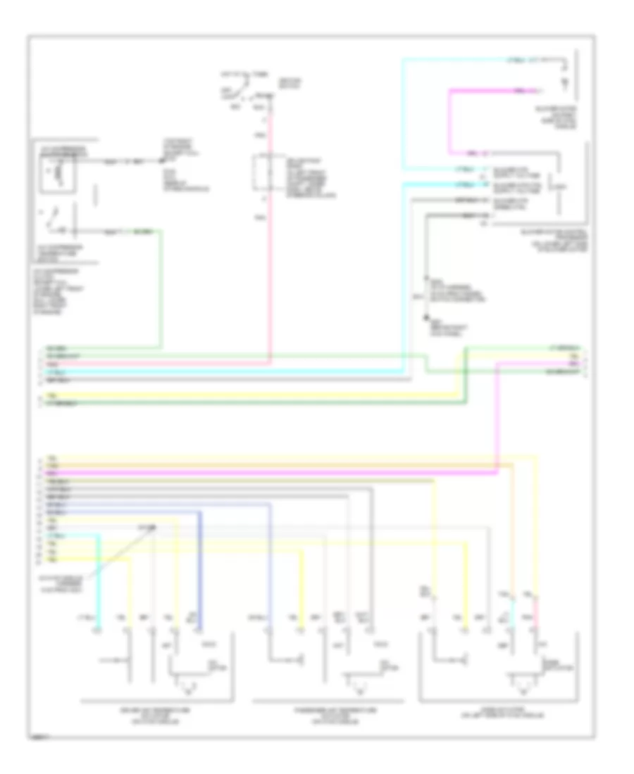
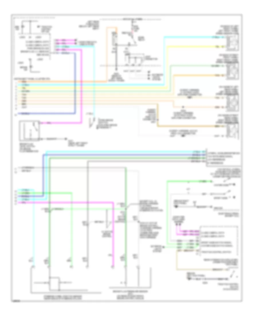
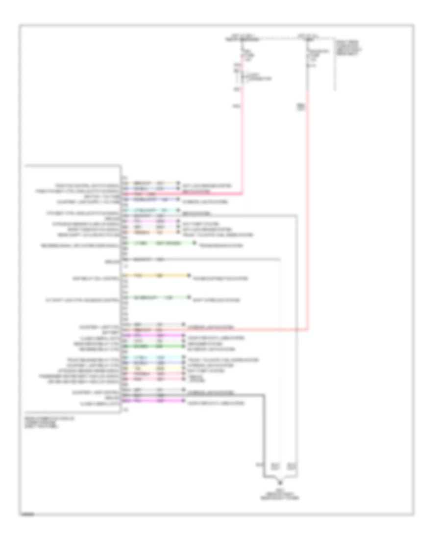
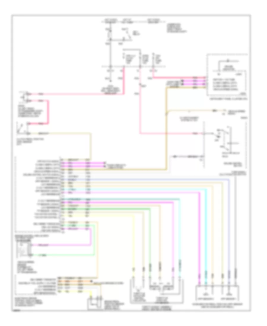
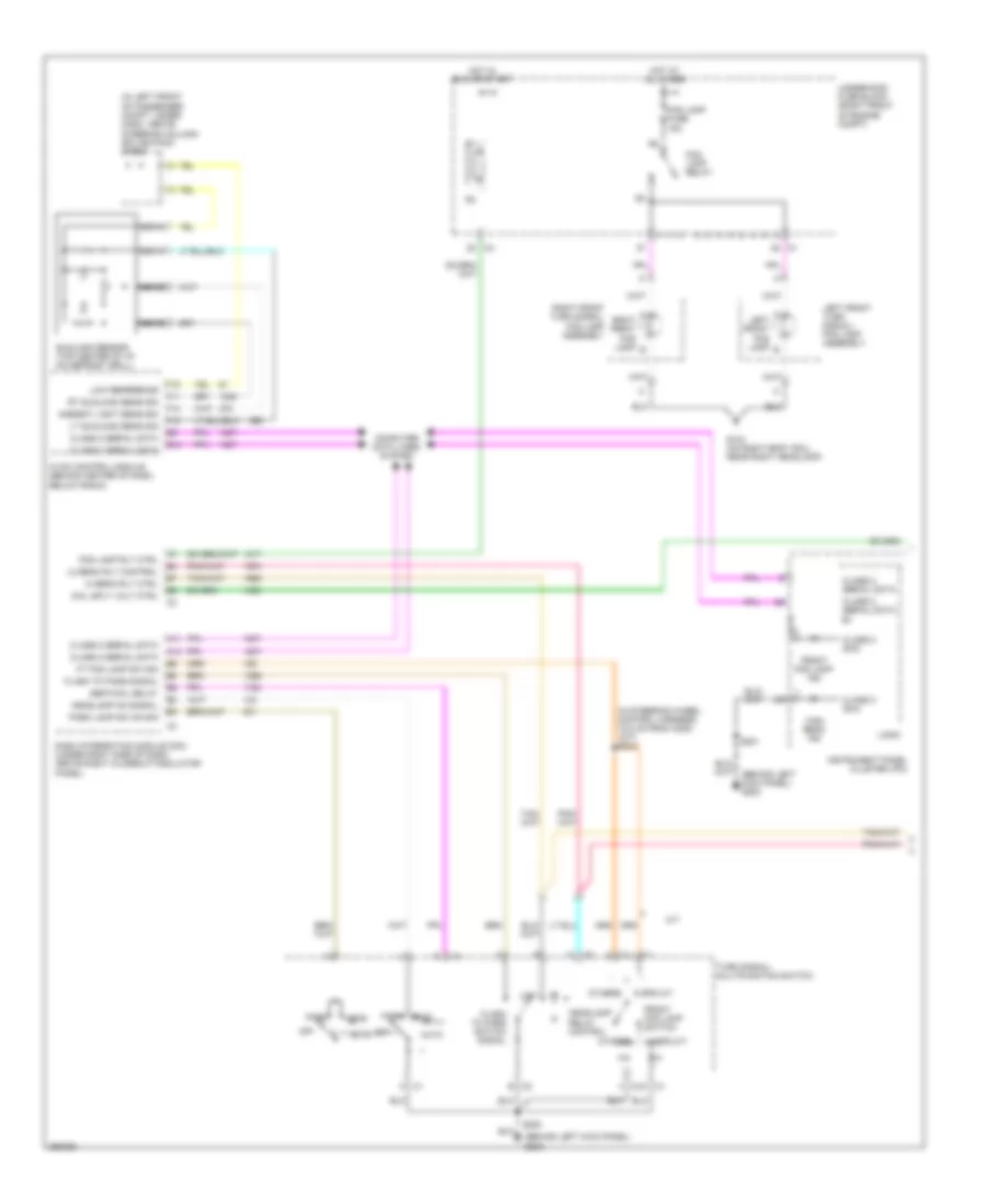
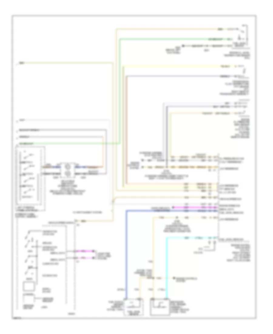
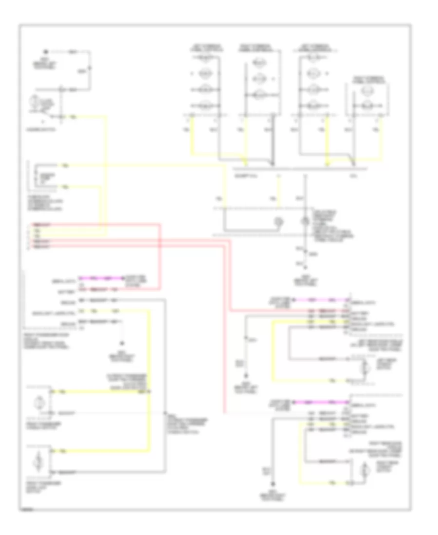
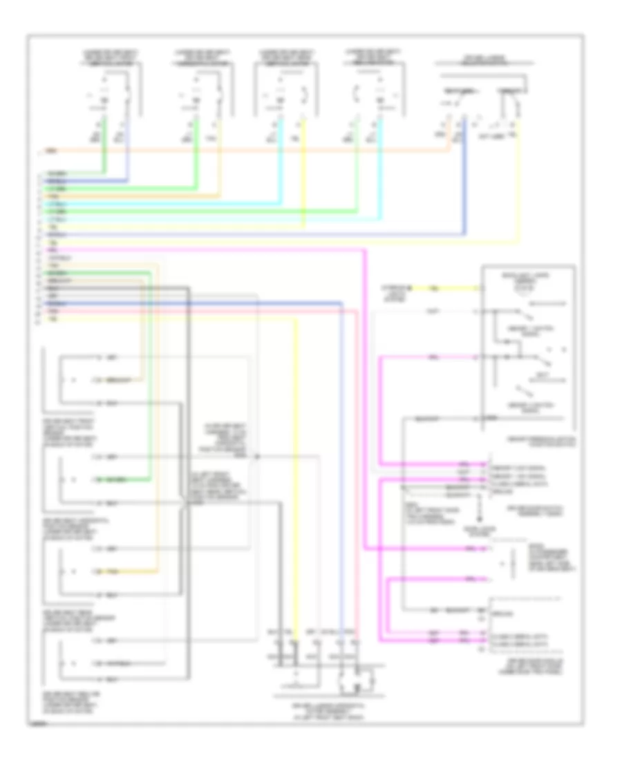
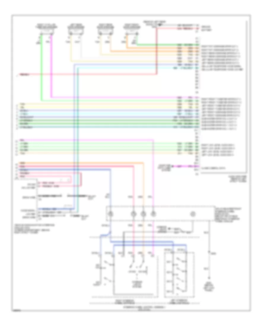
AIR CONDITIONING
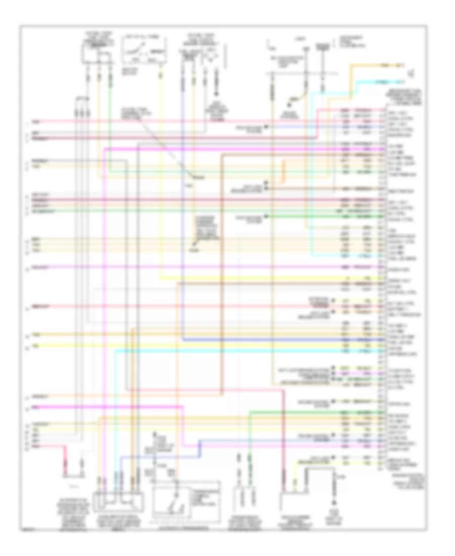
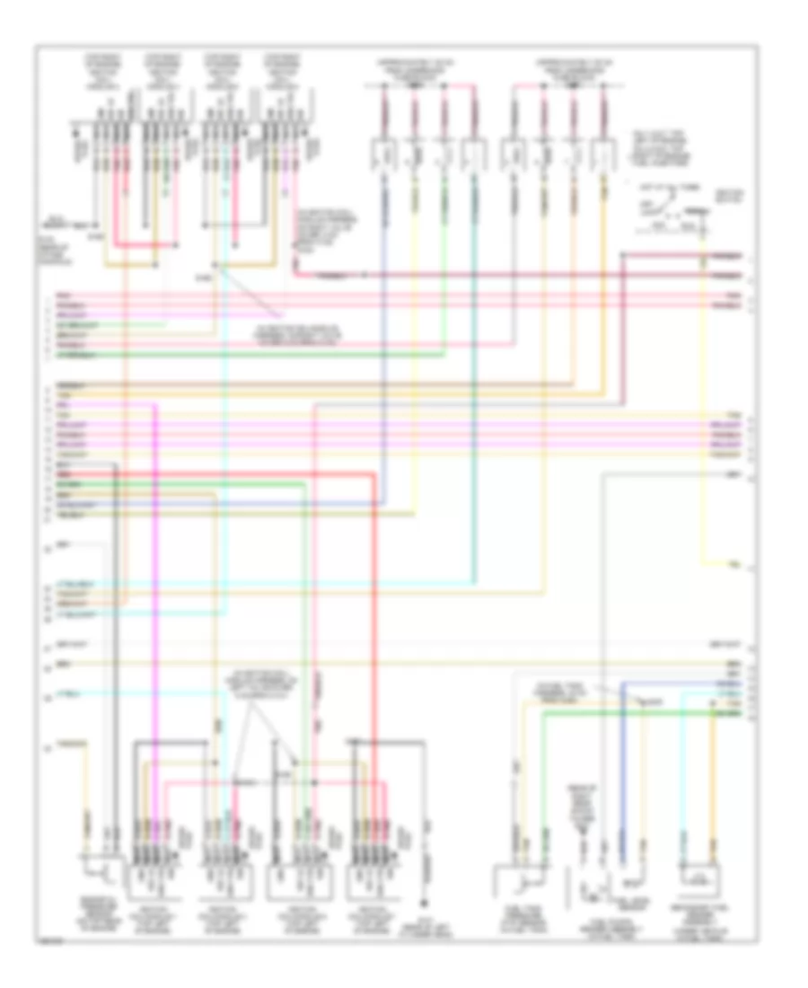
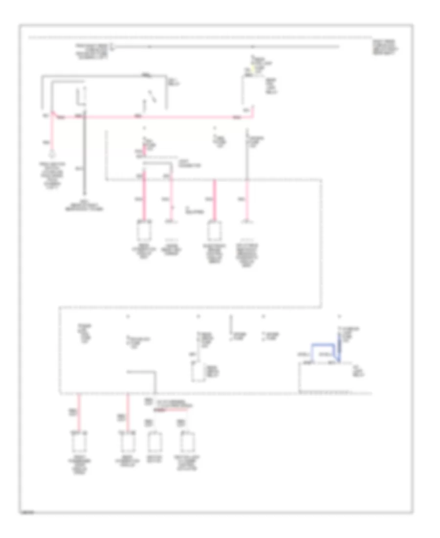
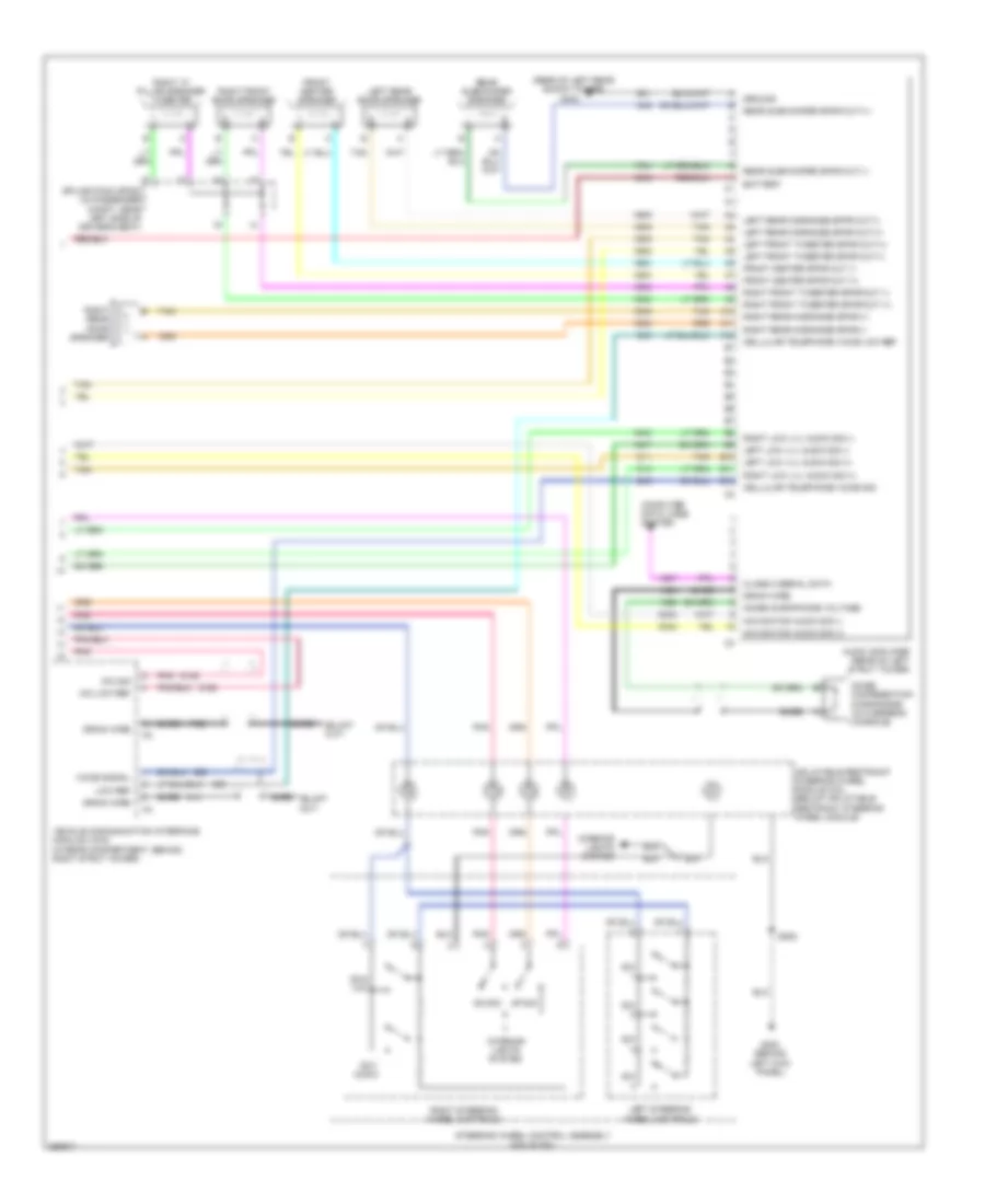
Automatic A/C Wiring Diagram (1 of 3) for Cadillac CTS V 2007
 https://portal-diagnostov.com/license.html
Automotive Electricians Portal FZCO
Automotive Electricians Portal FZCO
https://portal-diagnostov.com/license.html
https://portal-diagnostov.com/license.html
Automotive Electricians Portal FZCO
Automotive Electricians Portal FZCO
List of elements for Automatic A/C Wiring Diagram (1 of 3) for Cadillac CTS V 2007:
- 5 volt reference
- Air inlet motor
- Amb air temp sensor sig
- Ambient light sensor signal
- Battery positive voltage
- Blower fuse 40a
- Blower motor relay ctrl
- Blower mtr speed ctrl
- Blower relay mini
- Ccp fuse 10a
- Class 2 serial data
- Cmp clu relay micro
- Comp cltch fuse 10a
- Computer data lines system
- Door a
- Door b
- Dr air temp door ctrl a
- Dr air temp door ctrl b
- Driver air temp posit signal
- E10
- E11
- E12
- E13
- E14
- E15
- E16
- Evap temp sens signal
- Evaporator temperature sensor (on right side of evaporator case)
- F10
- F11
- F12
- F13
- F14
- F15
- F16
- G201 (behind right kick panel)
- Ground
- Hot at all times
- Hot in run
- Hvac control module (behind center of dash, below radio)
- Ign 3 fuse 10a
- Ignition 3 voltage
- Inside air temp sensor sig
- Inside air temperature sensor (behind dash, left of radio)
- Joint connector
- Left rear fuse block (below left rear seat)
- Left sunload sensor signal
- Low reference
- Mode door ctrl a
- Mode door ctrl b
- Mode door position signal
- Nca
- Pass air temp door ctrl a
- Pass air temp door ctrl b
- Pass air temp door posit
- Pnk
- R51
- R52
- R53
- R54
- R55
- R56
- R57
- R58
- Recirc door ctrl a
- Recirc door ctrl b
- Recirculation actuator (left side of blower motor)
- Right sunload sensor signal
- S117 (in hvac module harness, 6 cm from c321)
- Solid state
- Splice pack sp200 (in left front of passenger compt, under dash, above steering column)
- Sunload sensor (top center of i/p, on defrost grill)
- Tan
- Underhood fuse block (right front of engine compt)
- Volt
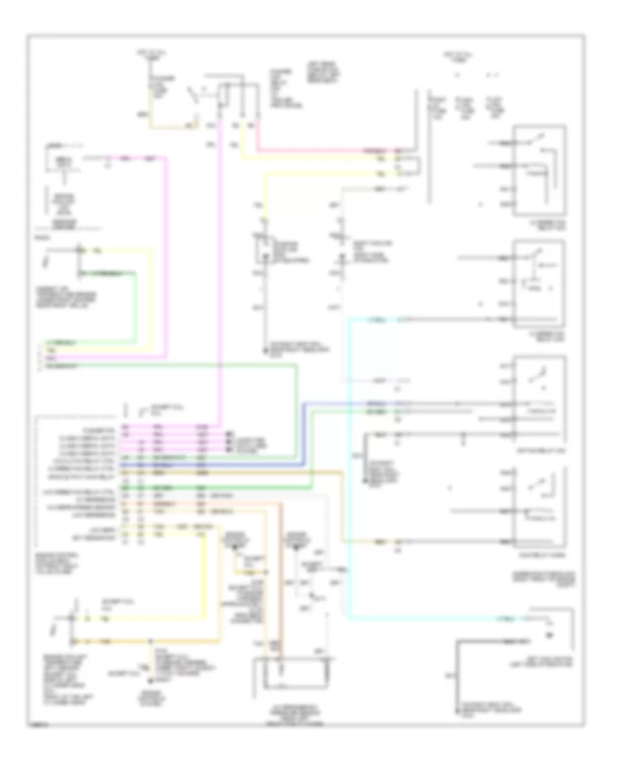
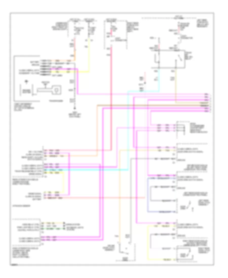
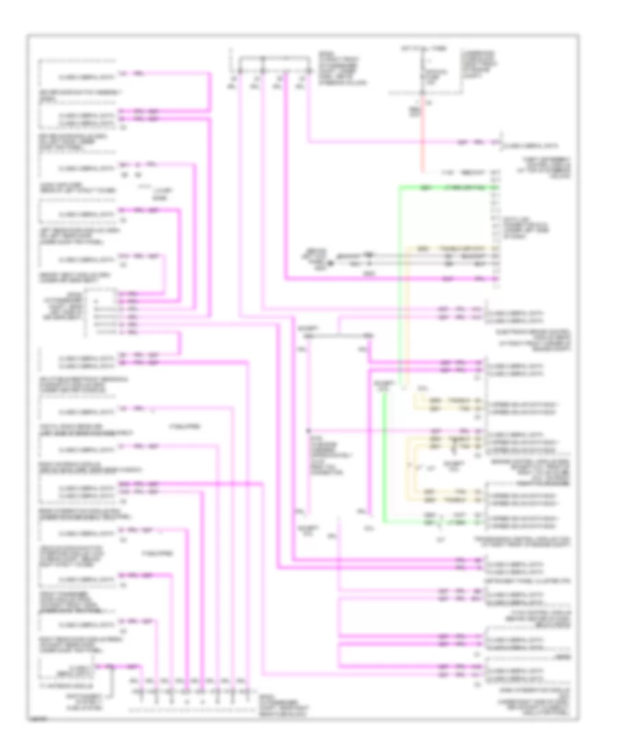
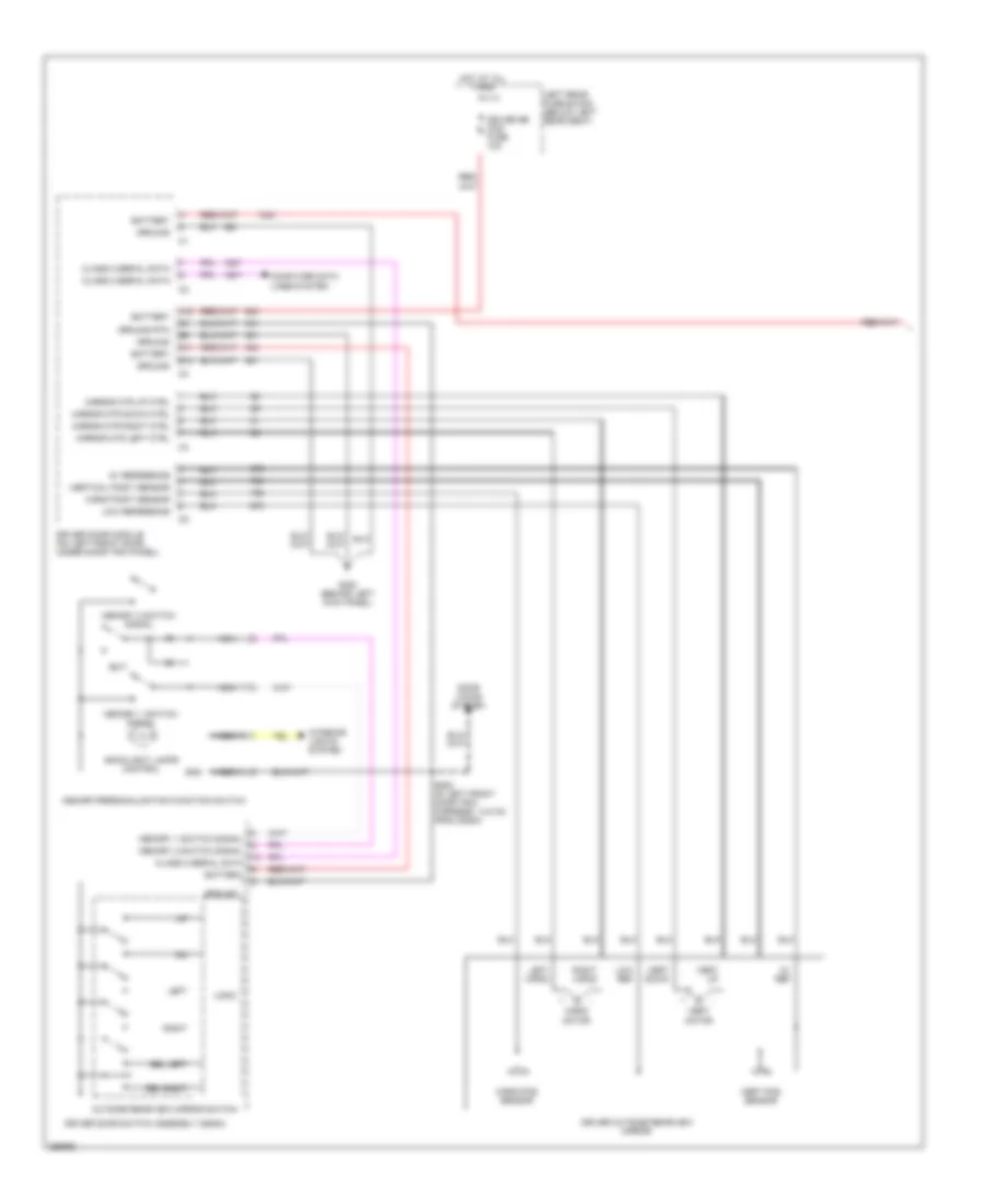
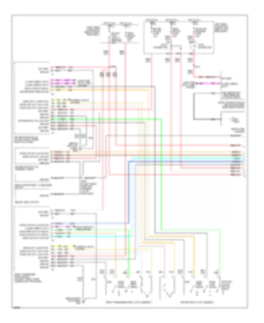
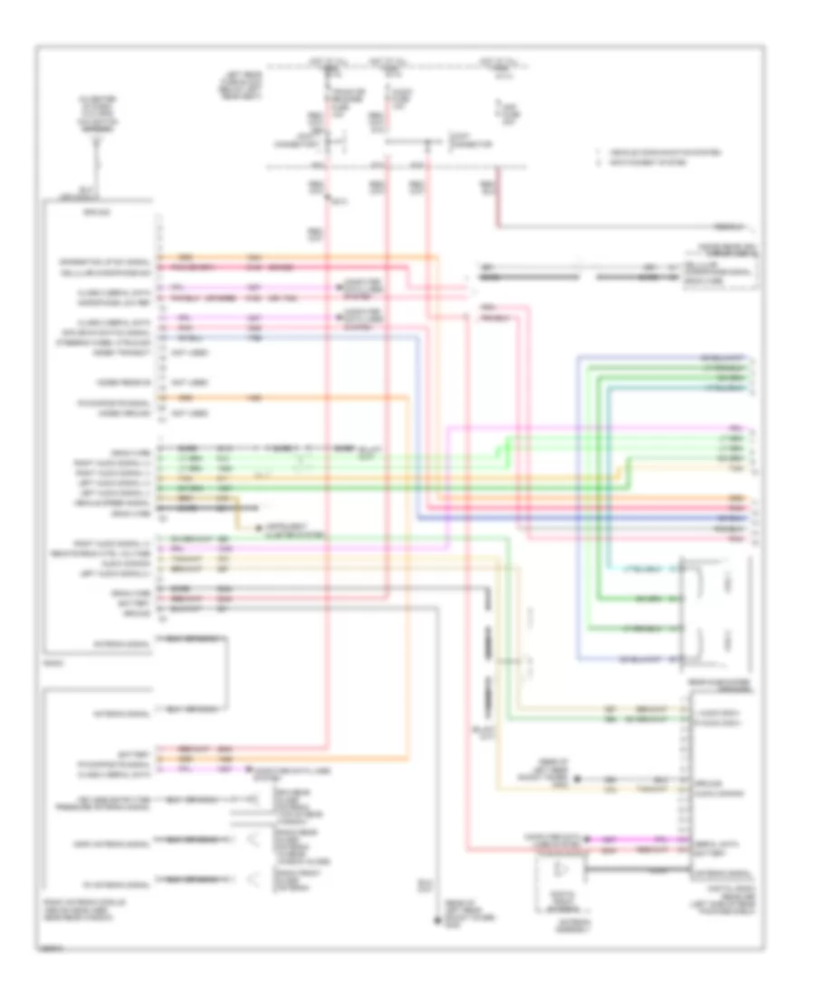
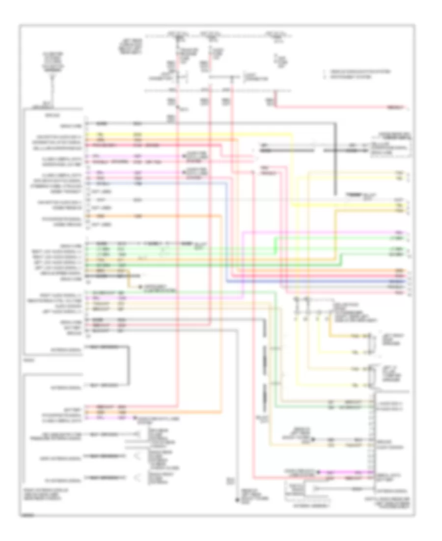
Automatic A/C Wiring Diagram (2 of 3) for Cadillac CTS V 2007
List of elements for Automatic A/C Wiring Diagram (2 of 3) for Cadillac CTS V 2007:
- (in hvac module harness, 6 cm from c321)
- (top right of engine) (except 6.0l) g132
- A/c
- A/c compressor clutch (except 6.0l: lower left front of engine) (6.0l: lower right front of engine)
- A/c compressor clutch solenoid
- A/c compressor temperature switch
- Acc
- Blower motor (on right side of hvac module)
- Blower motor control processor (on lower left side of blower motor)
- Blower mtr speed ctrl
- Cold
- Def
- Driver air temperature actuator (on hvac module)
- G142 (6.0l) (rear of intake manifold)
- G201 (behind right kick panel)
- Hot
- Hot at all times
- Ignition switch
- Logic
- Mix motor
- Mode actuator
- Mode actuator (on left side of hvac module)
- Nca
- Off/ lock
- Passenger air temperature actuator (on hvac module)
- Pnk
- Run
- S118
- S202 (in i/p harness, 48 cm from hazard switch connector)
- Splice pack sp200 (in left front of passenger compt, under dash, above steering column)
- Start
- Tan
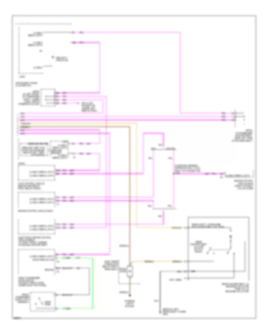
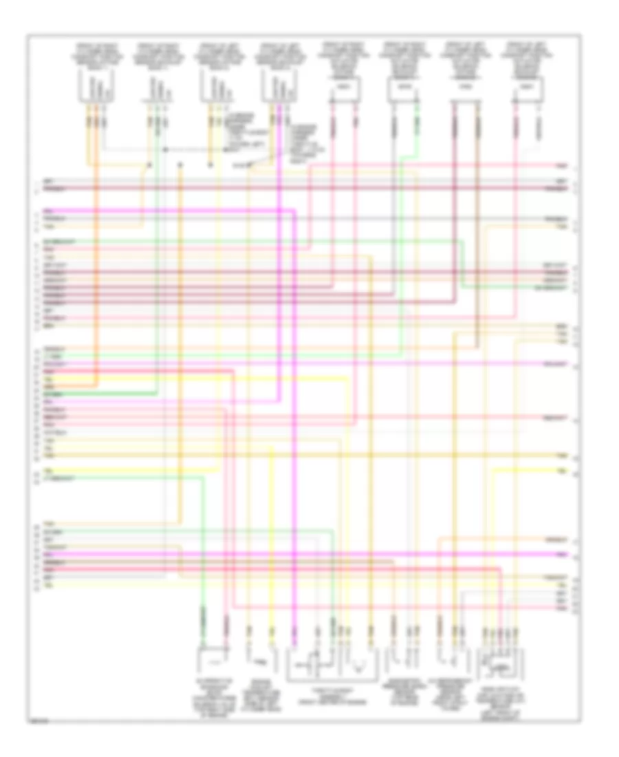
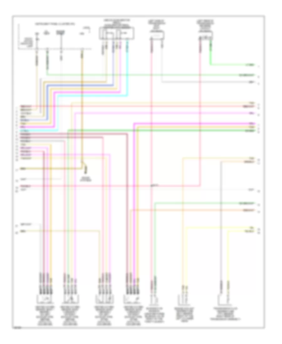
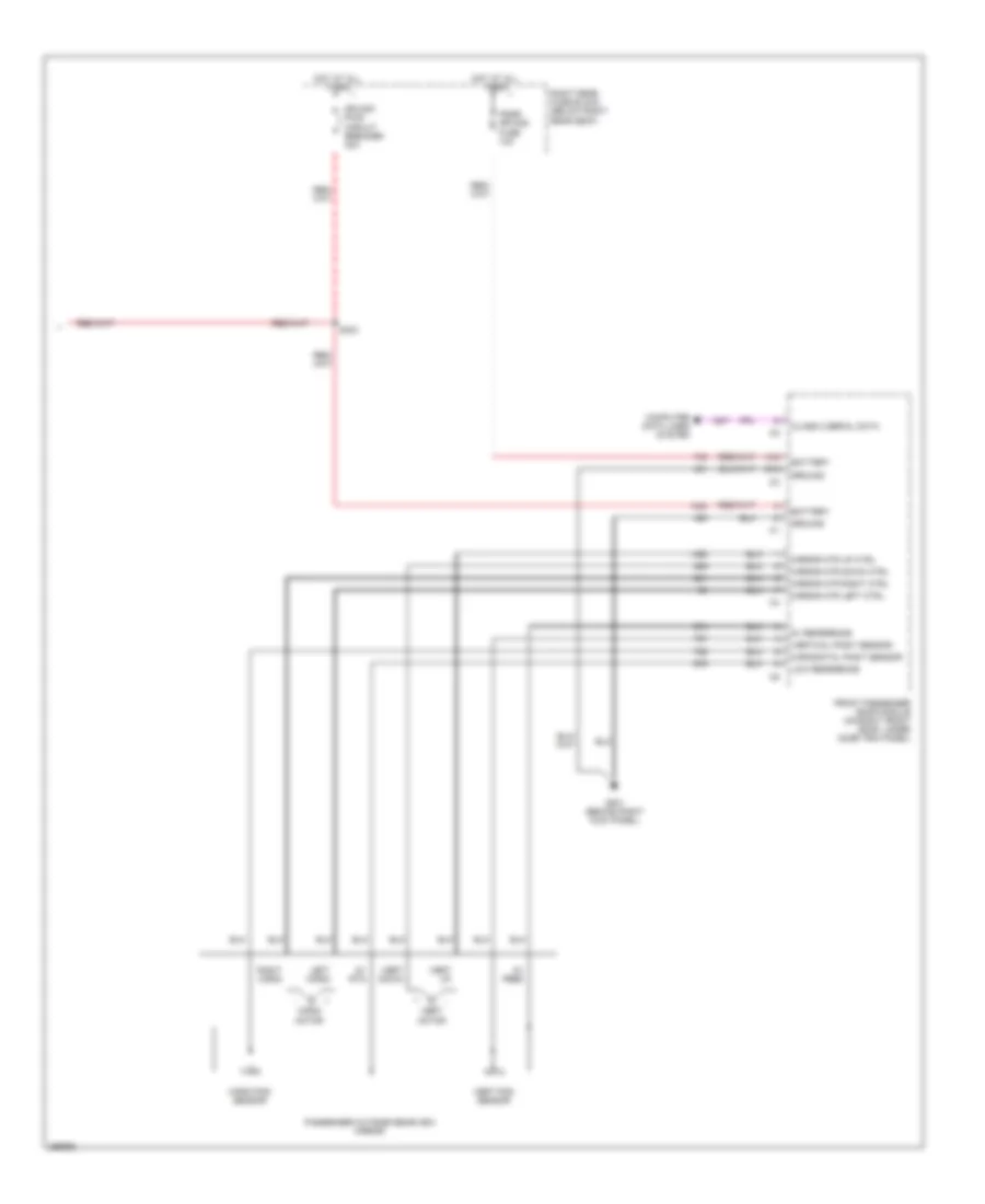
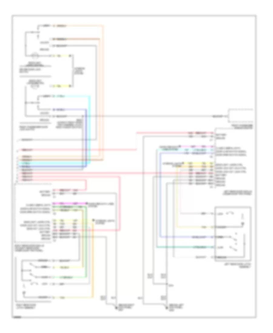
Automatic A/C Wiring Diagram (3 of 3) for Cadillac CTS V 2007
List of elements for Automatic A/C Wiring Diagram (3 of 3) for Cadillac CTS V 2007:
- (on right body rail, near right headlamp) g104
- (or 2700)
- (or 470)
- (or 5514)
- 5 refr
- 5v reference
- 6.0l
- A/c clutch relay ctrl
- A/c refrig press sensor
- A/c refrigerant pressure sensor (near left front strut tower)
- Ambient air temperature sensor (under front bumper, near front grille)
- Class 2 serial data
- Computer data lines system
- Drvr output main relay
- Ect sensor sig
- Engine control module (ecm) (on front right valve cover)
- Engine controls system
- Engine coolant low level
- Engine coolant temperature (ect) sensor (except 6.0l: side of left cylinder head) (6.0l: front of the left cylinder head)
- Except
- Except 6.0l
- Hi speed fan relay ctrl
- Hi speed fan relay mini
- High fan fuse 30a
- Hot at all times
- Left cooling fan (left side of radiator)
- Left rear fuse block (below left rear seat)
- Lo speed fan relay mini
- Logic
- Low fan fuse 30a
- Low reference
- Low refr
- Low speed fan relay ctrl
- Main relay micro
- Message center
- Nca
- Post o2 fuse 10a
- Pusher fan
- Pusher fan fuse 30a
- Pusher fan relay mini (w/ trailer provisions)
- Pushing cooling fan (if equipped)
- R10
- R14
- R15
- R16
- R17
- R18
- R19
- R20
- R21
- R22
- R39
- R40
- R41
- R42
- R47
- R48
- R49
- R50
- Radio
- Right cooling fan (right side of radiator)
- S/p fan relay mini
- S148 (except 6.0l) (in engine harness under throttle body, 11.5 cm towards right)
- S156 (except 6.0l) (in engine harness, approximately 24 cm from ebcm connector)
- S171
- Serial data
- Sig
- Tan
- Underhood fuse block (right front of engine compt)
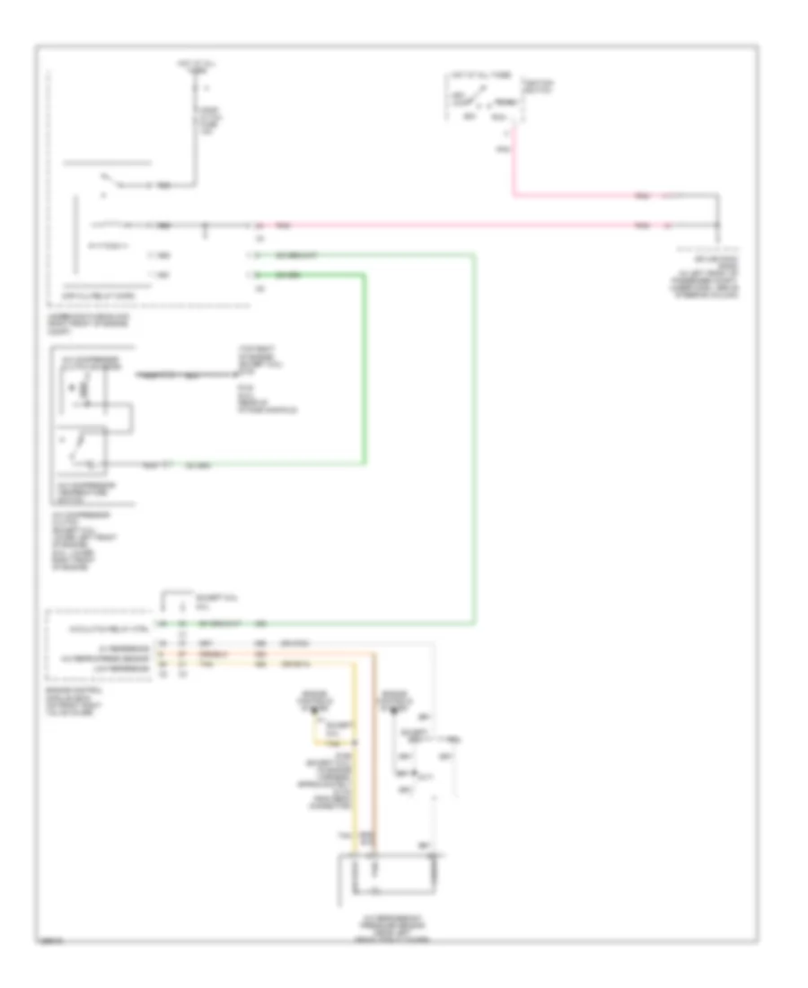
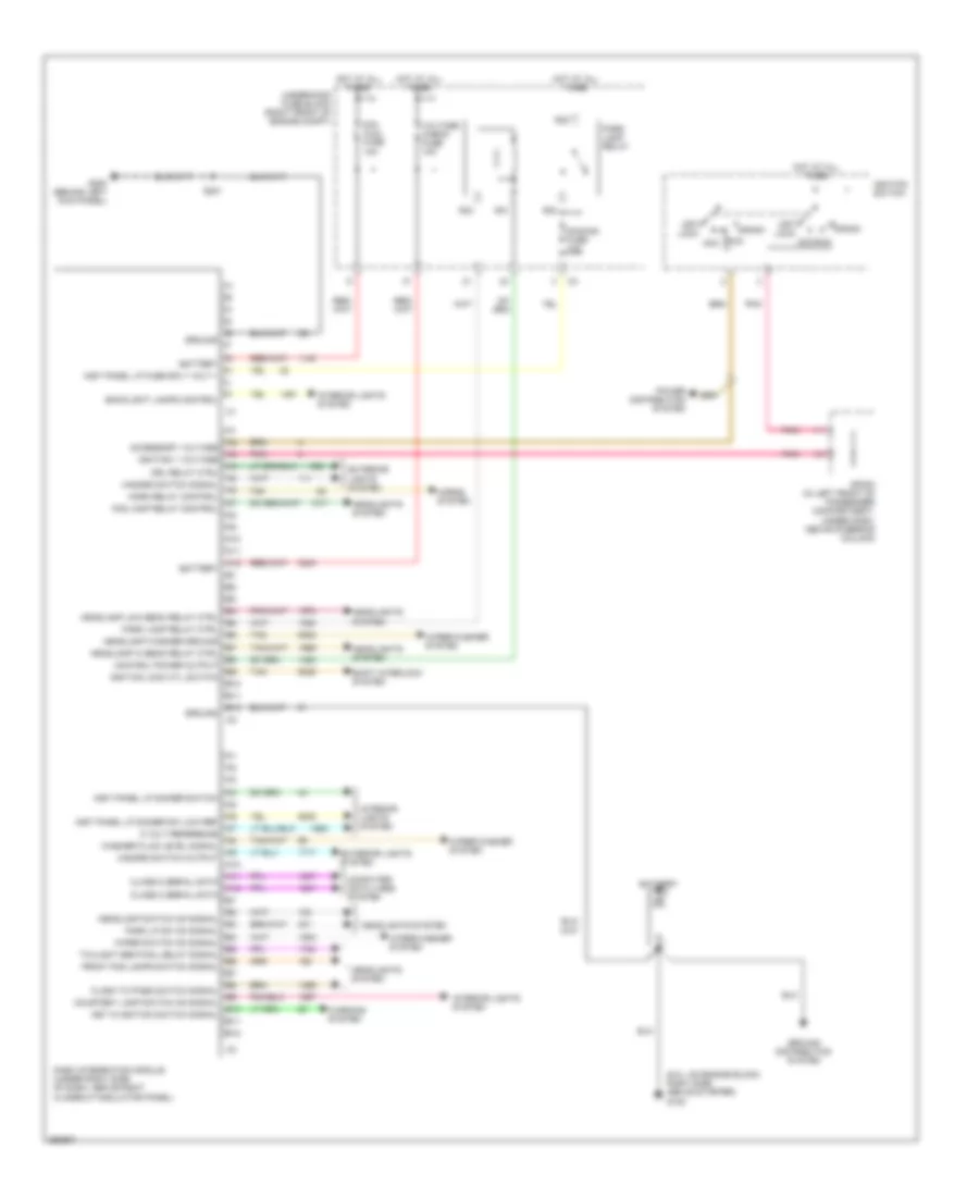
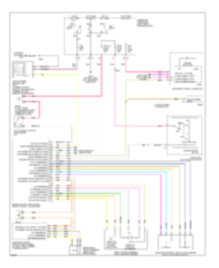
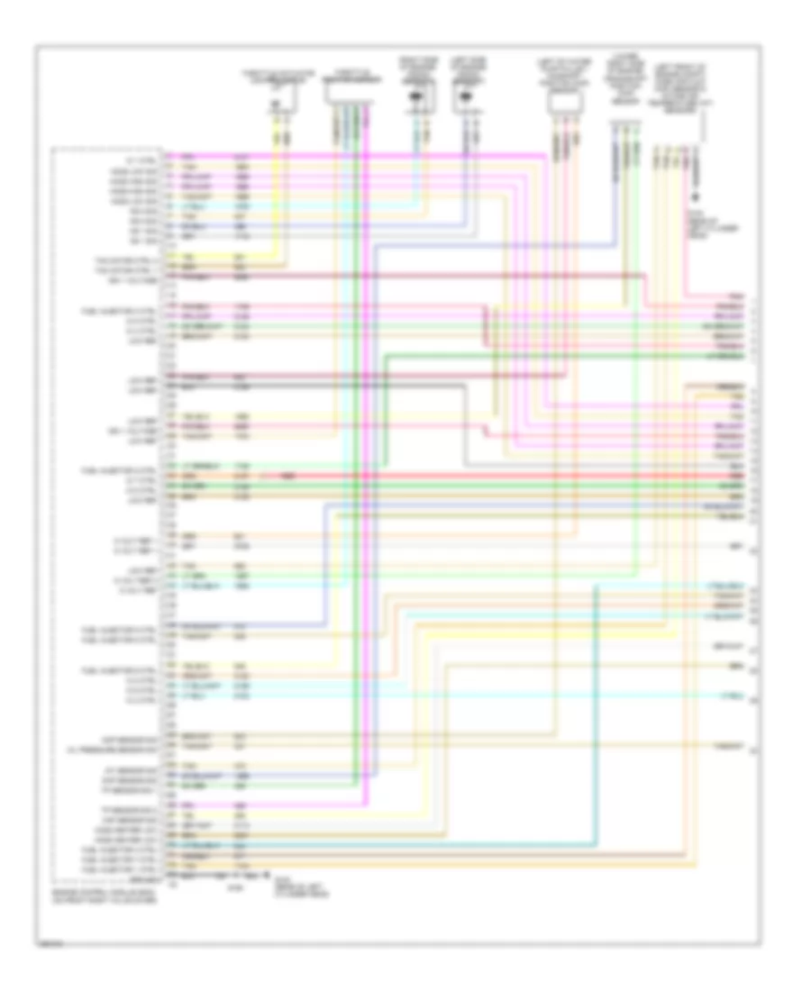
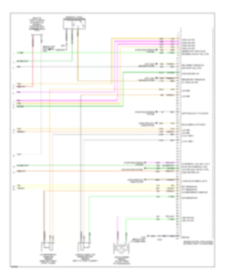
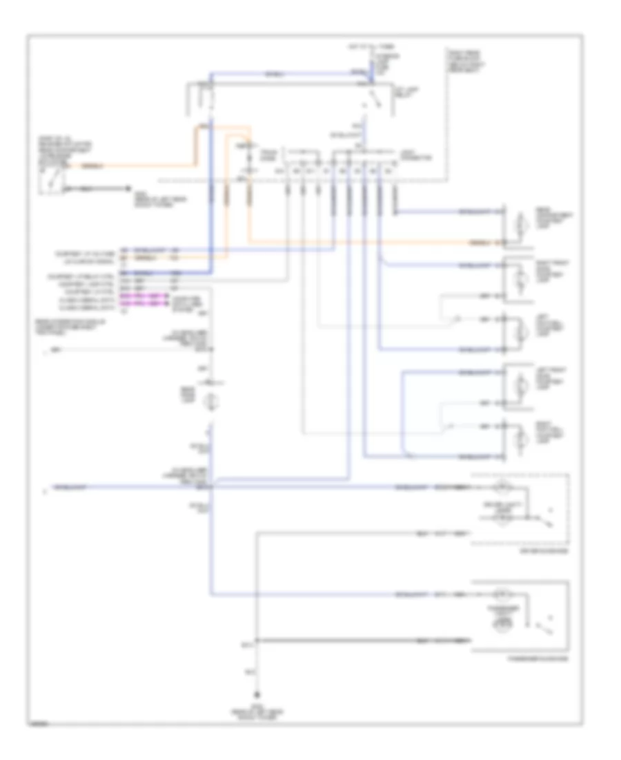
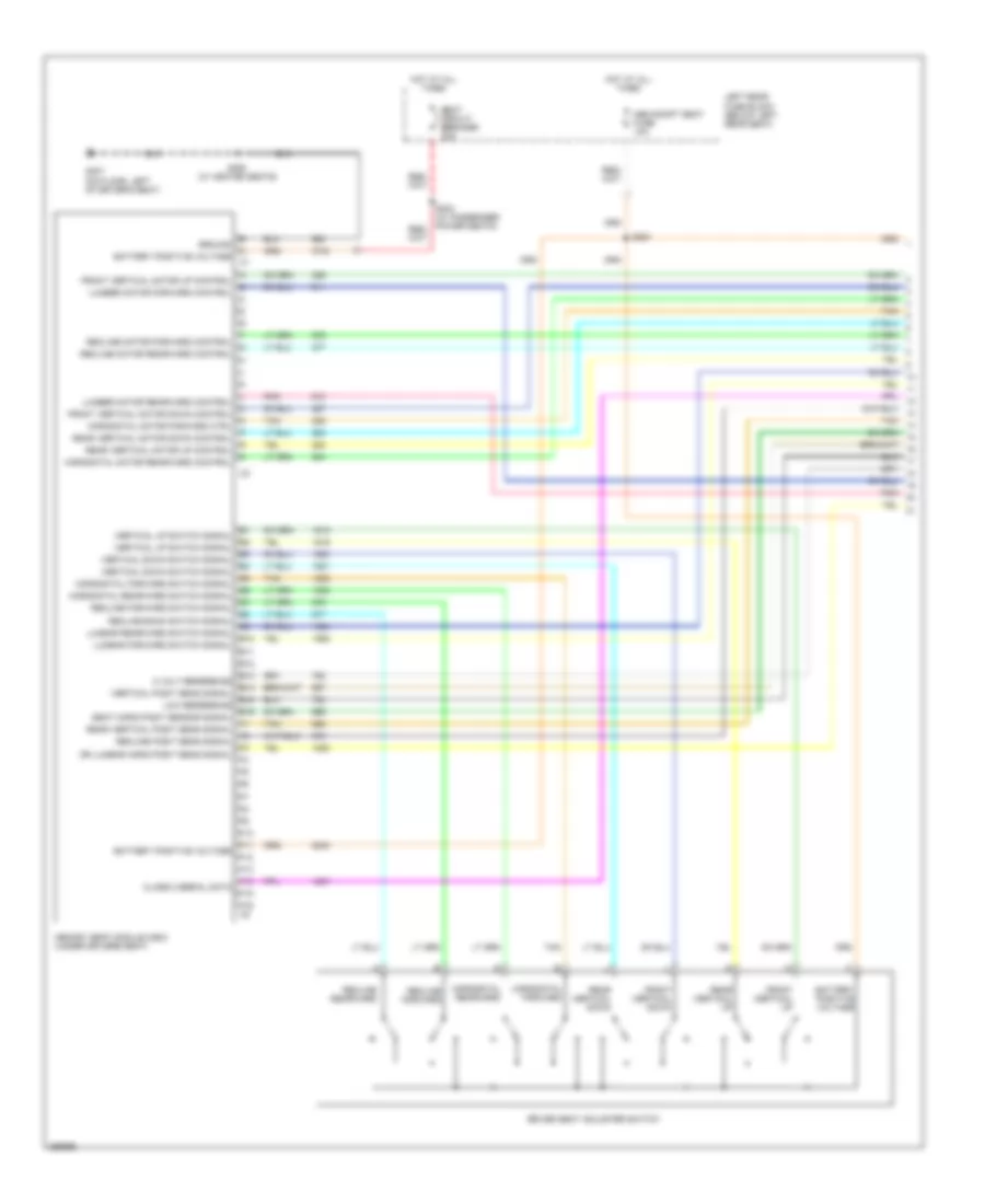
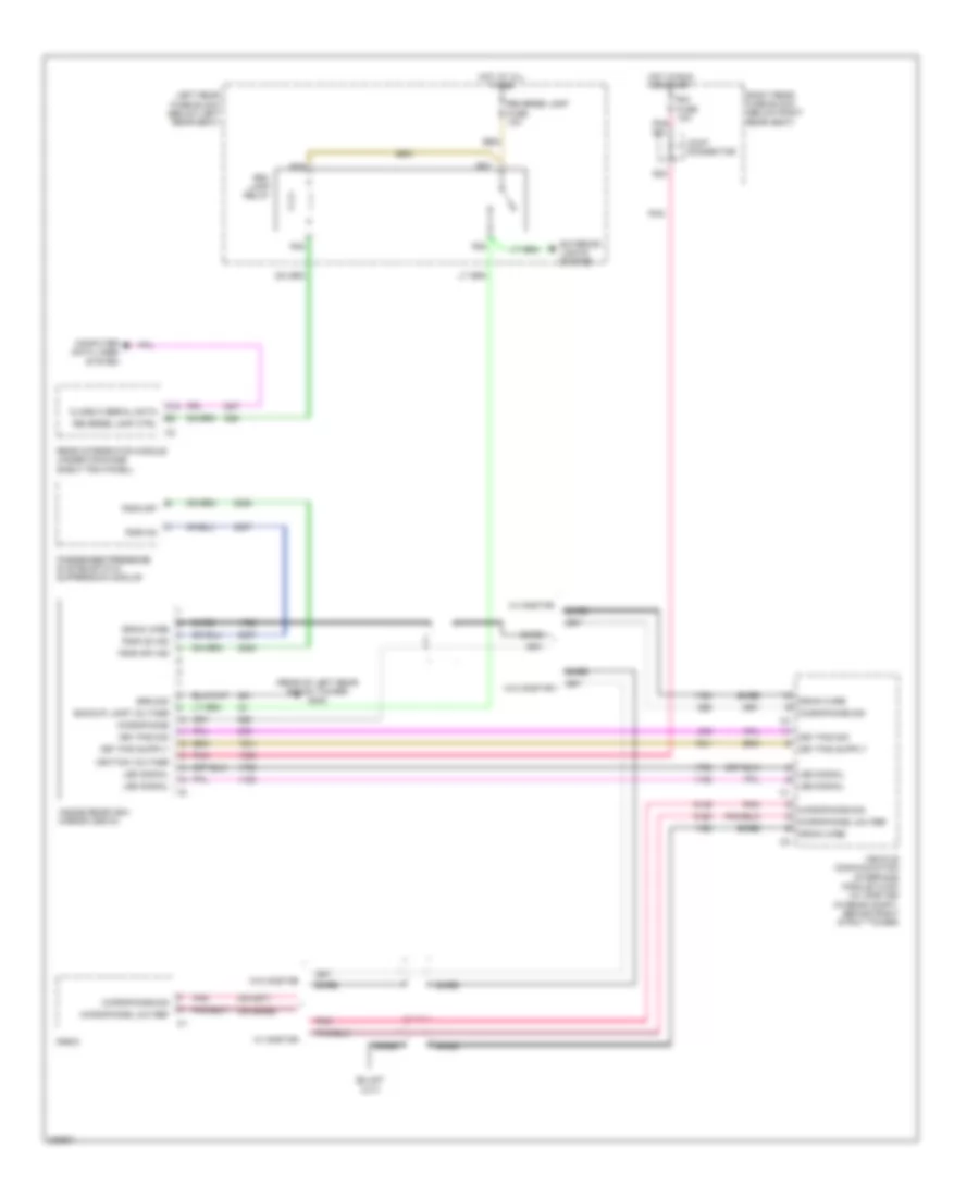
Compressor Wiring Diagram for Cadillac CTS V 2007
List of elements for Compressor Wiring Diagram for Cadillac CTS V 2007:
- (or 2700)
- (or 5514)
- (top right of engine) (except 6.0l) g132
- 5 refr
- 5v reference
- 6.0l
- A/c clutch relay ctrl
- A/c compressor clutch (except 6.0l: lower left front of engine) (6.0l: lower right front of engine)
- A/c compressor clutch solenoid
- A/c compressor temperature switch
- A/c refrig press sensor
- A/c refrigerant pressure sensor (near left front strut tower)
- Acc
- Cmp clu relay micro
- Comp cltch fuse 10a
- Engine control module (ecm) (on front right valve cover)
- Engine controls system
- Except
- Except 6.0l
- G142 (6.0l) (rear of intake manifold)
- Hot at all times
- Ignition switch
- Low reference
- Low refr
- Nca
- Off/ lock
- Pnk
- R55
- R56
- R57
- R58
- Run
- S156 (except 6.0l) (in engine harness, approximately 24 cm from ebcm connector)
- S171
- Sig
- Splice pack sp200 (in left front of passenger compt, under dash, above steering column)
- Start
- Tan
- Underhood fuse block (right front of engine compt)
ANTI-LOCK BRAKES
Anti-lock Brakes Wiring Diagram (1 of 2) for Cadillac CTS V 2007
List of elements for Anti-lock Brakes Wiring Diagram (1 of 2) for Cadillac CTS V 2007:
- (on right frame rail, near abs module) g110
- (rear of right rear shock tower) g401
- 5 volt reference
- 5-volt reference
- 6.0l
- A10
- A11
- A12
- A13
- A14
- Abs fuse 10a
- Abs fuse 50a
- Abs indicator sig
- B10
- B11
- B12
- B13
- B14
- Bpp sensor signal
- Brake fluid pressure sensor sig
- Brake pedal position sensor (near top of brake pedal)
- Brake pump motor
- C10
- C11
- C12
- C13
- C14
- Change brake pads service stability sys stability sys off stability sys ready stability sys engaged traction engaged traction suspended service suspension sys
- Class 2 serial data
- Computer data lines system
- Delivered torque signal
- Electronic brake control module (ebcm) (at right front corner of engine compartment)
- Engine control module (ecm) (6.0l: on front right valve cover) (except 6.0l: front of right valve cover)
- Except 6.0l
- Extended travel brake sw sig
- Extended travel brake switch sig
- Ground
- High effort ctrl
- Hot at all times
- Hot in run or start
- Ign 1 relay
- Lateral accelerometer signal
- Lf wheel speed sens low ref
- Lf wheel speed sens sig
- Logic
- Low effort ctrl
- Low reference
- Lr wheel speed sens low ref
- Lr wheel speed sens sig
- Message center
- Message request
- Nca
- Pnk
- R21
- R22
- R23
- R25
- Radio
- Requested torque signal
- Rf wheel speed sens low ref
- Rf wheel speed sens sig
- Right rear fuse block (below right rear seat)
- Rr wheel speed sens low ref
- Rr wheel speed sens sig
- S102
- S130
- S172
- Steering wheel position sig a
- Steering wheel position sig b
- Tan
- Throttle actuator control (tac) module
- Traction control data sig
- Traction control data signal
- Transmissions system
- Underhood fuse block (right front of engine compt)
- Variable effort steering actuator (on power steering rack assembly)
- W/ sport suspension system
- Yaw rate sensor signal
Anti-lock Brakes Wiring Diagram (2 of 2) for Cadillac CTS V 2007
List of elements for Anti-lock Brakes Wiring Diagram (2 of 2) for Cadillac CTS V 2007:
- (behind left kick panel) g200
- (behind right kick panel) g201
- (except 6.0l: in engine harness, 21 cm from variable effort steering actuator)
- (in body harness, 22.5 cm from vcim connector) s300
- (in body harness, 22.5 cm from vcim connector) s301
- (in body harness, 31 cm from audio amplifier connector) s306
- (on back of left front wheel) left front wheel speed sensor (wss)
- (on back of right front wheel) right front wheel speed sensor (wss)
- (on inside of left rear wheel) left rear wheel speed sensor (wss)
- (on inside of right rear wheel) right rear wheel speed sensor (wss)
- 5v reference
- A/t
- A12
- Abs ind
- Abs ind sig
- B12
- Bas fuse 15a
- Base relay
- Brake fluid level switch (on brake fluid reservoir)
- Brake fluid lvl sens sig
- Brake fluid pressure sensor (6.0l) (on rear of electronic brake control module)
- Brake ind
- Class 2 serial data
- Computer data lines system
- Electronic prndl (except 6.0l)
- Exterior lights system
- G101 (near left front strut tower)
- G402 (rear of left rear shock tower)
- Ground
- Hot at all times
- Instrument panel cluster (ipc)
- Joint connector
- Lateral accelerometer sig
- Left rear fuse block (below left rear seat)
- Logic
- Low reference
- Park brake sw sig
- Park brake switch (on park brake assembly)
- Rear integration module (rim) (under package shelf trim panel)
- S100 (w/ active brake control) (in engine harness, 4.5 cm from where pre ho2s branches from main harness)
- S101 (w/ active brake control)
- S200
- S302 (in body harness, 36 cm from audio amplifier connector)
- Sport mode
- Sport mode switch signal
- Steering wheel position sensor (near middle of steering column)
- Tan
- Traction control off ind
- Traction control switch
- Traction control switch (in glove box)
- W/ active brake control
- Winter mode
- Winter mode switch signal
- Yaw rate & lateral acceleration sensor (w/ active brake control) (under center console)
- Yaw rate sens signal
ANTI-THEFT
Anti-theft Wiring Diagram (1 of 2) for Cadillac CTS V 2007
List of elements for Anti-theft Wiring Diagram (1 of 2) for Cadillac CTS V 2007:
- A11
- A12
- Accessory voltage
- Alarm on signal
- Armed signal
- B10
- B12
- Battery
- C (not used)
- Class 2 serial data
- Control pwr output
- Dash integration module (under right side of dash, above right closeout/ insulator panel)
- Door open
- Door open switch signal
- Driver door latch assembly
- Driver door module (on left front door, under door trim panel.
- Ecm/tcm fuse 10a
- Exterior lights system
- F (not used)
- G200 (behind left kick panel)
- Ground
- Horn relay ctrl
- Horns system
- Hot at all times
- Hot in acc or run
- Hot in run or start
- Ign 1 voltage
- Ignition key
- Intrusion sensor
- Joint connector
- Left rear door latch assembly
- Left rear door module (under door trim panel)
- Left rear fuse block (below left rear seat)
- Nca
- Park lamp relay ctrl
- Pnk
- R31
- R32
- R33
- R35
- Reader/ exciter
- Rear compt lid ajar switch signal
- Rear integration module (under package shelf trim panel)
- Right rear door latch assembly
- Right rear door module (on right rear door, under door trim panel)
- Right rear fuse block (below right rear seat)
- Rim fuse 10a
- S20
- S205
- S21
- S22
- S23
- S313
- Sp303 (in passenger compartment, near right rear fuse block)
- Tan
- Theft deterrent control module (at top of steering column)
- Theft fuse 7.5a
- Transponder
- Trunk dr rel sol relay
- Trunk dr release fuse 10a
- Trunk release relay ctrl
- Underhood fuse block (right front of engine compt)
Anti-theft Wiring Diagram (2 of 2) for Cadillac CTS V 2007
List of elements for Anti-theft Wiring Diagram (2 of 2) for Cadillac CTS V 2007:
- (in engine harness, approximately 18 cm from tcm connector) s154
- (not used)
- (rear of left rear shock tower) g402
- 2.8l/3.6l
- 6.0l
- A13
- A14
- B10
- Class 2
- Class 2 serial data
- Data link connector (under left side of dash)
- Door open
- Door open sw sig
- E10
- Electronic brake control module (ebcm) (at right front corner of engine compartment)
- Engine control module (ecm)
- Engine control module (ecm) (front of right valve cover)
- Front passenger door latch assembly
- Front passenger door module (on right front door, under door trim panel)
- Gnd
- Ground
- Hvac control module (behind center of dash, below radio)
- Instrument panel cluster (ipc)
- Interior lights system
- Logic
- Message center
- Message request
- Radio
- Rear compartment lid ajar switch signal
- Rear compartment lid release actuator (part of lid release actuator)
- Right rear fuse block (below right rear seat)
- Security indicator
- Service theft sys starting disabled- remove key theft attempted
- Sp200 (in left front of passenger compt, under dash, above steering column)
- Sp300 (in passenger compartment, near left side of driver's seat)
- Trunk diode
BODY CONTROL MODULES
Dash Integration Module Wiring Diagram for Cadillac CTS V 2007
List of elements for Dash Integration Module Wiring Diagram for Cadillac CTS V 2007:
- (6.0l: on engine block, right side, above starter) g102
- 5 volt reference
- A10
- A11
- A12
- Acc
- Accessory voltage
- B10
- B11
- B12
- Backlight lamps control
- Battery
- Class 2 serial data
- Computer data lines system
- Control power output
- Courtesy lamp switch on signal
- Crank
- Dash integration module (under right side of dash, above right closeout/insulator panel)
- Dim/ aldl fuse 10a
- Dimming fuse 10a
- Drl relay ctrl
- Exterior lights system
- Flash to pass switch signal
- Fog lamp relay control
- Front fog lamps switch signal
- G200 (behind left kick panel)
- Ground
- Ground distribution system
- Hazard switch output
- Hazard switch signal
- Headlamp hi beam relay ctrl
- Headlamp low beam relay ctrl
- Headlamp switch on signal
- Headlamp washer ground
- Headlights system
- Horn relay control
- Horns system
- Hot at all times
- Ignition 1 voltage
- Ignition lock cyl switch
- Ignition switch
- Inst panel lp dimmer sw low ref
- Inst panel lp dimmer switch
- Inst panel lp fuse sply volt 1
- Interior lights system
- Key in ignition switch signal
- Off/ lock
- Park lamp relay
- Park lamp relay ctrl
- Park lp sw on signal
- Pnk
- Power distribution system
- R31
- R32
- R33
- R34
- Run
- S201
- Shift interlock system
- Sp200 (in left front of passenger compartment, under dash, above steering column)
- Tan
- Twilight sentinal delay signal
- Underhood fuse block (right front of engine compt)
- Voltage check fuse 10a
- Warning system
- Washer fluid level signal
- Wiper switch on signal
- Wiper/washer system
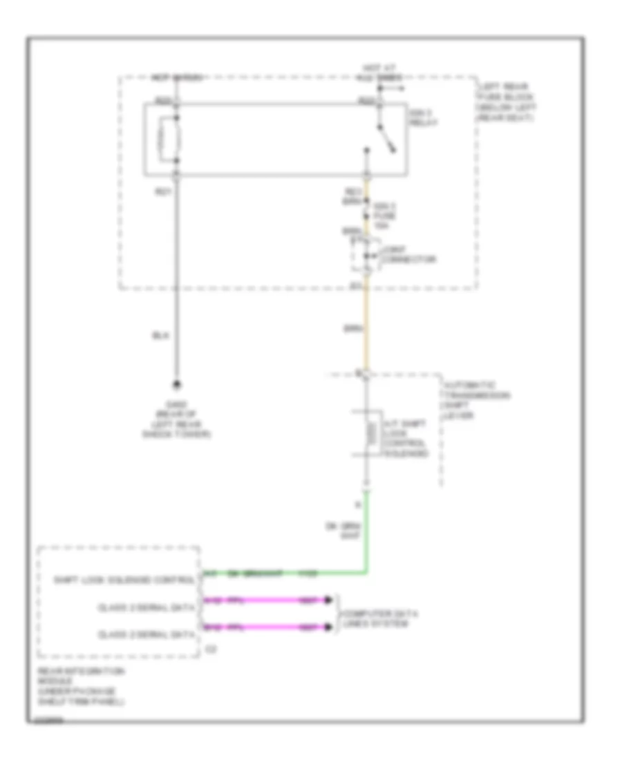
Rear Integration Module Wiring Diagram for Cadillac CTS V 2007
List of elements for Rear Integration Module Wiring Diagram for Cadillac CTS V 2007:
- 5007 (or 5053)
- A/t shift lock ctrl solenoid control
- A10
- A11
- A12
- Anti-lock brakes system
- Anti-theft system
- B10
- B11
- B12
- Battery
- Class 2 serial data
- Computer data lines system
- Courtesy lamp control
- Courtesy lamp ctrl
- Courtesy lamp relay ctrl
- Defogger system
- Driver heated seat high/low signal
- Exterior lights system
- G401 (rear of right rear shock tower)
- Ground
- Hot at all times
- Hot w/ ign 1 relay energized
- Htd seat ctrl module status signal
- Ignition 1 voltage
- Interior lights system
- Intrusion sensor alarm on signal
- Intrusion sensor armed signal
- Joint connector
- Pass htd seat ctrl module status signal
- Passenger heated seat high/low signal
- Pnk
- Power distribution system
- Rap relay coil control
- Rear compt lid ajar switch sig
- Rear defog relay ctrl
- Rear integration module (under package shelf trim panel)
- Reverse relay ctrl
- Reverse signal (or winter mode signal)
- Right rear fuse block (below right rear seat)
- Rim fuse 10a
- Rim/ign sw fuse 10a
- S21
- S22
- Seats system
- Shift interlock system
- Sport mode switch signal
- Tan
- Traction control switch signal
- Transmissions system
- Trunk release relay ctrl
- Trunk, tailgate, fuel doors system
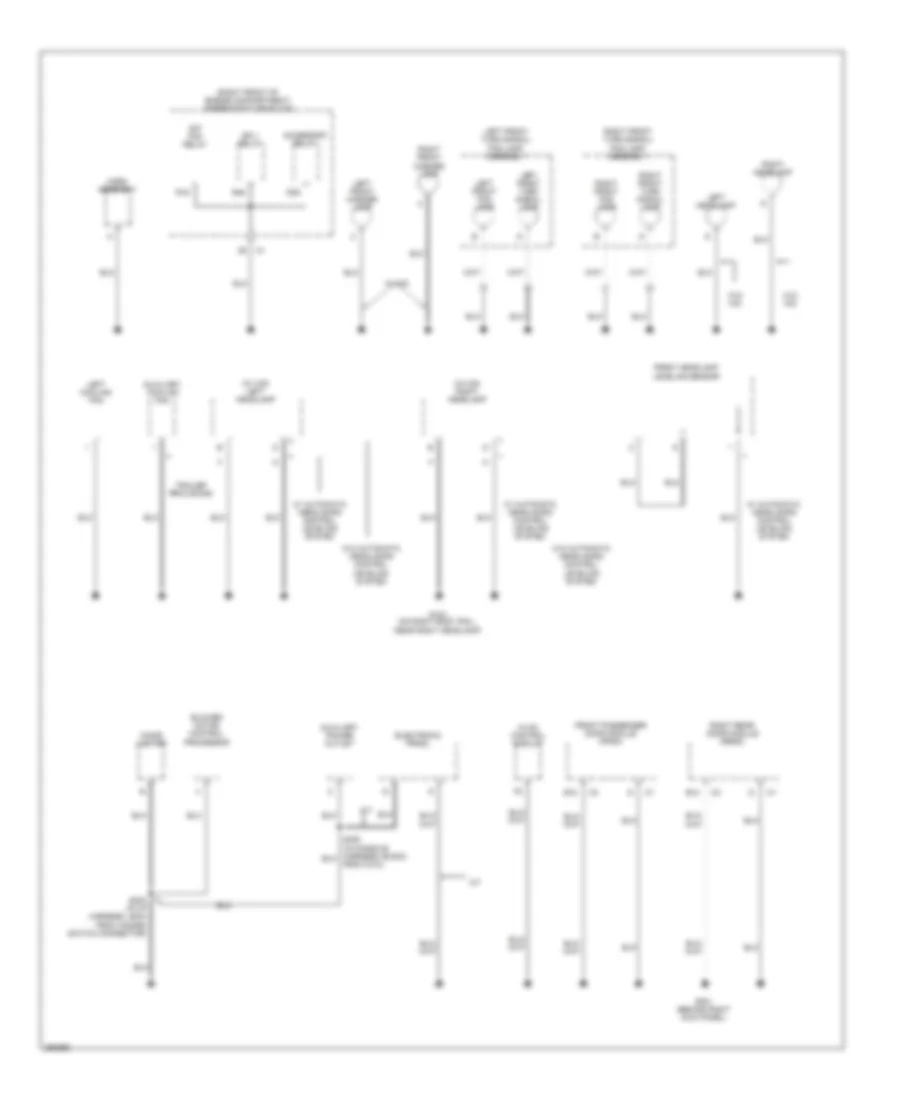
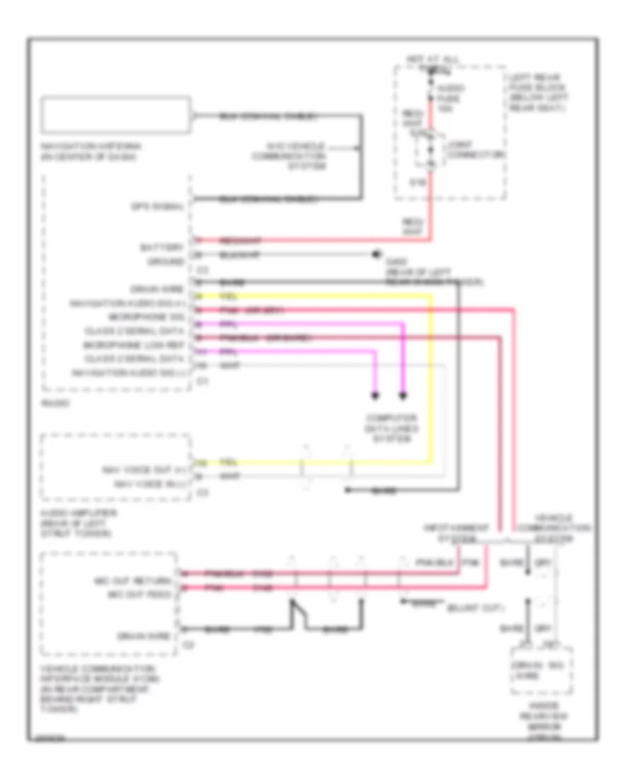
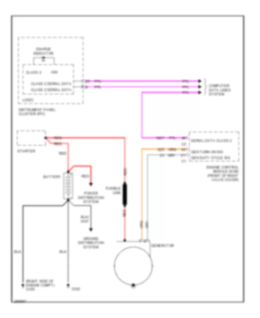
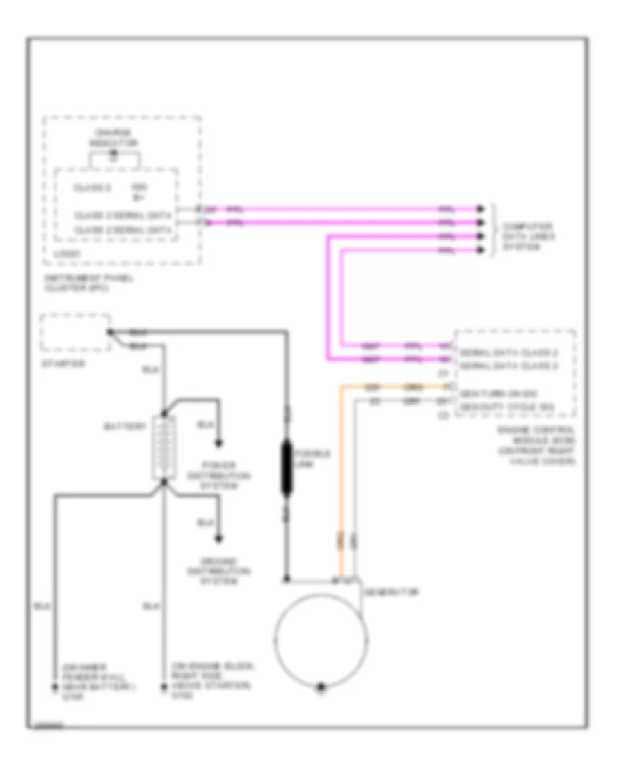
COMPUTER DATA LINES
Computer Data Lines Wiring Diagram for Cadillac CTS V 2007
List of elements for Computer Data Lines Wiring Diagram for Cadillac CTS V 2007:
- (behind left kick panel) g200
- 6.0l
- A/t
- A11
- A12
- A13
- A14
- Audio amplifier (rear of left strut tower)
- B11
- B12
- Base
- Class 2 serial data
- Dash integration module (dim) (under right side of dash, above right closeout/ insulator panel)
- Data link connector (dlc) (under left side of dash)
- Digital radio receiver (left side of rear package shelf)
- Dim/aldl fuse 10a
- Driver door module (ddm) (on left door, under door trim panel)
- Driver door switch assembly (ddsa)
- E10
- Electronic brake control module (ebcm) (at right front corner of engine compt)
- Engine control module (ecm) (except 6.0l: front of right valve cover) (6.0l: on front right valve cover)
- Except
- Except 6.0l
- F14
- Front passenger door module (fpdm) (on right front door, under door trim panel)
- H speed gmlan data bus +
- H speed gmlan data bus -
- Hot at all times
- Hvac control module (behind center of dash, below radio)
- If equipped
- Inflatable restraint sensing & diagnostic module (sdm) (under center console)
- Infotainment system 7/ avec system
- Instrument panel cluster (ipc)
- Left rear door module (lrdm) (on left rear door, under door trim panel)
- Luxury
- Memory seat module (msm) (under driver's seat)
- Radio
- Radio antenna module (above headliner, near rear window)
- Rear integration module (rim) (under package shelf trim panel)
- Right rear door module (rrdm) (on right rear door, under door trim panel)
- S154 (in engine harness, approximately 18 cm from tcm connector)
- S200
- S201
- Sp200 (in right front of passenger compt, under dash, above steering column)
- Sp300 (in passenger compt, near left side of driver's seat)
- Sp303 (in passenger compt, near right rear fuse block)
- Tan
- Theft deterrent control module (at top of steering column)
- Transmission control module (tcm) (at right front of engine compt)
- Tv antenna module
- Underhood fuse block (right front of engine compt)
- Vehicle communication interface module (vcim) (in rear compt, behind right strut tower)
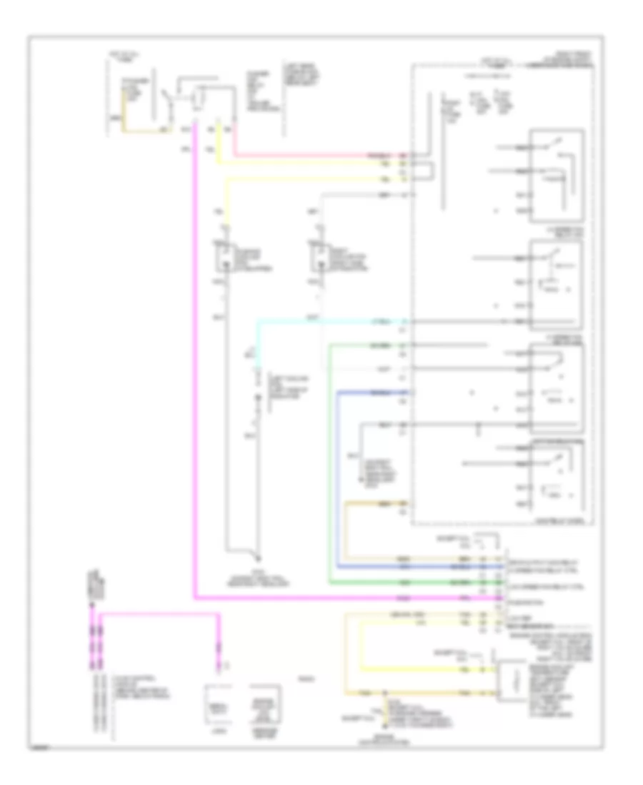
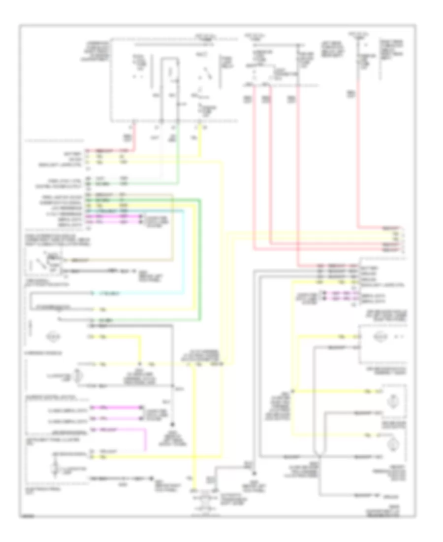
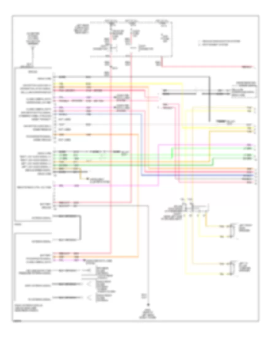
COOLING FAN
Cooling Fan Wiring Diagram for Cadillac CTS V 2007
List of elements for Cooling Fan Wiring Diagram for Cadillac CTS V 2007:
- (on right body rail, near right headlamp) g104
- (or 470)
- (right front of engine compt) underhood fuse block
- 6.0l
- Class 2 serial data
- Computer data lines system
- Drvr output main relay
- E10
- Ect sensor sig
- Engine control module (ecm) (except 6.0l: front of right valve cover) (6.0l: on front right valve cover)
- Engine controls system
- Engine coolant low level
- Engine coolant temperature (ect) sensor (except 6.0l: side of left cylinder head) (6.0l: front of the left cylinder head)
- Except 6.0l
- G104 (on right body rail, near right headlamp)
- Hi fan fuse 30a
- Hi speed fan relay ctrl
- Hi speed fan relay mini
- Hot at all times
- Hvac control module (behind center of dash, below radio)
- Left cooling fan (left side of radiator)
- Left rear fuse block (below left rear seat)
- Lo speed fan relay mini
- Logic
- Low fan fuse 30a
- Low ref
- Low speed fan relay ctrl
- Main relay micro
- Message center
- Nca
- Post o2 fuse 10a
- Pusher fan fuse 30a
- Pusher fan relay mini (w/ trailer provisions)
- Pushing cooling fan (if equipped)
- Pushing fan
- R10
- R14
- R15
- R16
- R17
- R18
- R19
- R20
- R21
- R22
- R39
- R40
- R41
- R42
- R47
- R48
- R49
- R50
- Radio
- Right cooling fan (right side of radiator)
- S/p fan relay mini
- S148 (except 6.0l) (in engine harness under throttle body, 11.5 cm towards right)
- Serial data
- Tan
CRUISE CONTROL
2.8L VIN T
2.8L VIN T, Cruise Control Wiring Diagram for Cadillac CTS V 2007
List of elements for 2.8L VIN T, Cruise Control Wiring Diagram for Cadillac CTS V 2007:
- (top right of engine) g132
- 5 volt reference
- 5 volt reference 1
- 5 volt reference 3
- Accelerator pedal position (app) sensor (above accelerator pedal)
- App sensor 1 signal
- App sensor 2 signal
- Bpp sensor signal
- Brake pedal position sensor (near top of brake pedal)
- C12
- C13
- Class 2 serial data
- Clutch pedal position (cpp) sensor (m/t)
- Computer data lines system
- Cpp switch signal
- Cruise control switch
- Cruise control switch signal
- Cruise indicator
- Electronic brake control module (ebcm) (at right front corner of engine compt)
- Engine control module (ecm) (front of right valve cover)
- Extended travel brake sw sig
- G104 (on right body rail, near right headlamp)
- High speed gmlan ser data bus+
- High speed gmlan ser data bus-
- Hot at all times
- Hot in run or start
- Htr vlv/ cltch fuse 10a
- Ign 1 relay
- Ignition 1 voltage
- Instrument panel cluster (ipc)
- Logic
- Low reference
- Main relay
- Off
- Pnk
- R/a
- R43
- R44
- R45
- R46
- R48
- R49
- Radio
- S155
- S207
- Sp102
- Sp200 (in left front of passenger compt, under dash, above steering column)
- Strg ctls fuse 10a
- Tac motor control 1
- Tac motor control 2
- Tan
- Tcm/ ipc fuse 15a
- Throttle actuator control (tac) motor
- Throttle body assembly (front center of engine)
- Throttle position (tp) sensor
- Tos fuse 10a
- Tp sensor 1 signal
- Tp sensor 2 signal
- Turn signal/ multi-function switch
- Underhood fuse block (right front of engine compt)
- Vehicle speed sensor (vss) (m/t) (5 speed: on right rear of transmission) (6 speed: on left rear of transmission)
- Vehicle speed sensor signal
- Vehicle speed signal
- W/ infotainment system 5,7 & 8
3.6L VIN 7
3.6L VIN 7, Cruise Control Wiring Diagram for Cadillac CTS V 2007
List of elements for 3.6L VIN 7, Cruise Control Wiring Diagram for Cadillac CTS V 2007:
- (top right of engine) g132
- 5 volt reference
- 5 volt reference 1
- 5 volt reference 3
- Accelerator pedal position (app) sensor (above accelerator pedal)
- App sensor 1 signal
- App sensor 2 signal
- Bpp sensor signal
- Brake pedal position sensor (near top of brake pedal)
- C12
- C13
- Class 2 serial data
- Clutch pedal position (cpp) sensor (m/t)
- Computer data lines system
- Cpp switch signal
- Cruise control switch
- Cruise control switch signal
- Cruise indicator
- Electronic brake control module (ebcm) (at right front corner of engine compt)
- Engine control module (ecm) (front of right valve cover)
- Extended travel brake sw sig
- G104 (on right body rail, near right headlamp)
- High speed gmlan ser data bus+
- High speed gmlan ser data bus-
- Hot at all times
- Hot in run or start
- Htr vlv/ cltch fuse 10a
- Ign 1 relay
- Ignition 1 voltage
- Instrument panel cluster (ipc)
- Logic
- Low reference
- Main relay
- Off
- Pnk
- R/a
- R43
- R44
- R45
- R46
- R48
- R49
- Radio
- S155
- S207
- Sp102
- Sp200 (in left front of passenger compt, under dash, above steering column)
- Strg ctls fuse 10a
- Tac motor control 1
- Tac motor control 2
- Tan
- Tcm/ ipc fuse 15a
- Throttle actuator control (tac) motor
- Throttle body assembly (front center of engine)
- Throttle position (tp) sensor
- Tos fuse 10a
- Tp sensor 1 signal
- Tp sensor 2 signal
- Turn signal/ multi-function switch
- Underhood fuse block (right front of engine compt)
- Vehicle speed sensor (vss) (m/t) (5 speed: on right rear of transmission) (6 speed: on left rear of transmission)
- Vehicle speed sensor signal
- Vehicle speed signal
- W/ infotainment system 5,7 & 8
6.0L VIN U
6.0L VIN U, Cruise Control Wiring Diagram for Cadillac CTS V 2007
List of elements for 6.0L VIN U, Cruise Control Wiring Diagram for Cadillac CTS V 2007:
- 5 volt reference
- 5 volt reference 1
- 5 volt reference 2
- Accelerator pedal position (app) sensor (above accelerator pedal)
- Anti-lock brakes system
- App sensor 1
- App sensor 1 signal
- App sensor 2
- App sensor 2 signal
- Bpp sensor signal
- Brake pedal position sensor (near top of brake pedal)
- C12
- C13
- Class 2 serial data
- Clutch pedal position (cpp) sensor (m/t)
- Computer data lines system
- Cpp switch signal
- Cruise control switch
- Cruise control switch signal
- Cruise indicator
- Delivered torque sig
- Electronic brake control module (ebcm) (at right front corner of engine compt)
- Engine control module (ecm) (on front right valve cover)
- G104 (on right body rail, near right headlamp)
- Hot at all times
- Hot in run or start
- Htr vlv/ cltch fuse 10a
- Ign 1 relay
- Ignition 1 voltage
- Instrument panel cluster (ipc)
- Logic
- Low reference
- Off
- Pnk
- R/a
- R43
- R44
- R45
- R46
- Radio
- S207
- Sp200 (in left front of passenger compt, under dash, above steering column)
- Strg ctls fuse 10a
- Tac motor control 1
- Tac motor control 2
- Tan
- Tcm/ ipc fuse 15a
- Throttle actuator control (tac) motor
- Throttle body assembly (front center of engine)
- Throttle position (tp) sensor
- Tp sensor
- Tp sensor 1 signal
- Tp sensor 2 signal
- Turn signal/ multi-function switch
- Underhood fuse block (right front of engine compt)
- Vehicle speed sensor (6 speed m/t) (on left rear of transmission)
- Vehicle speed signal
- Vss high signal
- Vss low signal
- W/ infotainment system 5,7 & 8
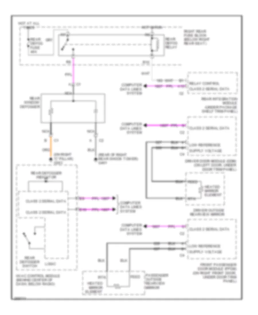
DEFOGGERS
Defoggers Wiring Diagram for Cadillac CTS V 2007
List of elements for Defoggers Wiring Diagram for Cadillac CTS V 2007:
- (on right "c" pillar) g303
- (rear of right rear shock tower) g401
- A12
- Class 2 serial data
- Computer data lines system
- Driver door module (ddm) (on left door, under door trim panel)
- Driver outside rearview mirror
- E10
- Feed
- Front passenger door module (fpdm) (on right front door, under door trim panel)
- Heated mirror element
- Hot at all times
- Hot in run
- Hvac control module (behind center of dash, below radio)
- Logic
- Low reference
- Nca
- Passenger outside rearview mirror
- R10
- Rear defog fuse 40a
- Rear defog relay
- Rear defogger indicator
- Rear defogger switch
- Rear integration module (under package shelf trim panel)
- Rear window defogger
- Relay control
- Right rear fuse block (below right rear seat)
- Rtn
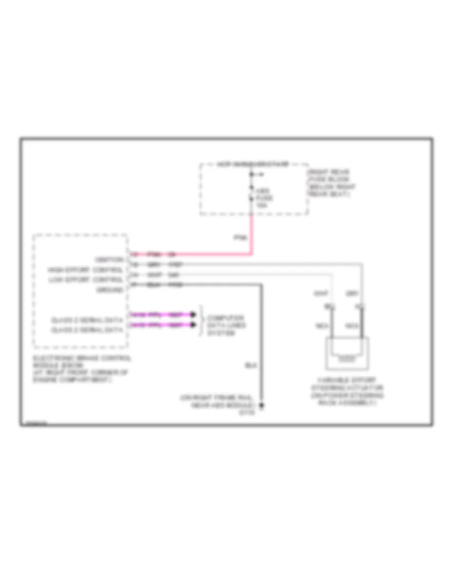
ELECTRONIC POWER STEERING
Electronic Power Steering Wiring Diagram for Cadillac CTS V 2007
List of elements for Electronic Power Steering Wiring Diagram for Cadillac CTS V 2007:
- (on right frame rail, near abs module) g110
- A13
- A14
- Abs fuse 10a
- Class 2 serial data
- Computer data lines system
- Electronic brake control module (ebcm) (at right front corner of engine compartment)
- Ground
- High effort control
- Hot in run or start
- Ignition
- Low effort control
- Nca
- Pnk
- Right rear fuse block (below right rear seat)
- Variable effort steering actuator (on power steering rack assembly)
ENGINE PERFORMANCE
2.8L VIN T
2.8L VIN T, Engine Performance Wiring Diagram (1 of 4) for Cadillac CTS V 2007
List of elements for 2.8L VIN T, Engine Performance Wiring Diagram (1 of 4) for Cadillac CTS V 2007:
- (in engine harness, 20 cm from pcm) s140
- (in fuel injector harness, 10 cm from c121)
- (in oil filter housing) engine oil pressure (eop) sensor
- +5v
- +5v ref
- Bare
- Baro sig
- Ckp sens lo
- Ckp sensor sig
- Cmp sig
- Cmp sol ctrl
- Crankshaft position sensor (right side of engine)
- Drain
- Ect sig
- Engine control module (front of right valve cover)
- Evap sol ctrl
- Fuel injectors
- G133 (right front of engine)
- Gen fdc sig
- Gen to sig
- Heated oxygen sensor bank 1 sensor 1 (in right exhaust pipe, before catalytic converter)
- Heated oxygen sensor bank 1 sensor 2 (in right exhaust pipe, after catalytic converter)
- Heated oxygen sensor bank 2 sensor 1 (in left exhaust pipe, before catalytic converter)
- Heated oxygen sensor bank 2 sensor 2 (in left exhaust pipe, after catalytic converter)
- Ho2s lo ctrl
- Ho2s lo ref
- Ho2s pmp ct
- Ho2s ref volt
- Ic 1 ctrl
- Ic 2 ctrl
- Ic 3 ctrl
- Ic 4 sig
- Ic 5 ctrl
- Ic 6 ctrl
- Imrc sol ctrl
- Inj 1 ctrl
- Inj 2 ctrl
- Inj 3 ctrl
- Inj 4 ctrl
- Inj 5 ctrl
- Inj 6 ctrl
- Intake manifold runner control solenoid (center rear of intake manifold)
- Knock sensor (bank 1) (right side of engine)
- Knock sensor (bank 2) (left side of engine)
- Ks 1 sig
- Ks 2 sig
- Low ref
- Nca
- Oil pres sig
- Pnk
- S141 (in engine harness, 15 cm from pcm)
- Starting/ charging system
- Tac mtr ctrl 1
- Tac mtr ctrl 2
- Tan
- Tan a
- Tp sig 1
- Tp2 sig
2.8L VIN T, Engine Performance Wiring Diagram (2 of 4) for Cadillac CTS V 2007
List of elements for 2.8L VIN T, Engine Performance Wiring Diagram (2 of 4) for Cadillac CTS V 2007:
- (in engine harness, 15 cm from coil 1)
- (in engine harness, 15 cm from coil 5)
- (in engine harness, 24.5 cm from ect sensor)
- (left rear of engine)
- Canister vent fuse 10a
- Ecm fuse 15a
- Ecm/tcm fuse 10a
- Even inj/ coil fuse 20a
- Fuel pump motor relay
- G104 (on right body rail, near right headlamp)
- G130 (rear of right cylinder head)
- G131
- G401 (rear of right rear shock tower)
- Hot at all times
- Hot in acc or run
- Hot in run or start
- Ign 1 relay
- Ign mod/ maf fuse 15a
- Ignition coil 1 (top right of engine)
- Ignition coil 2 (top left of engine)
- Ignition coil 3 (top right of engine)
- Ignition coil 4 (top left of engine)
- Ignition coil 5 (top right of engine)
- Ignition coil 6 (top left of engine)
- Main relay
- Nca
- Odd inj/ coil fuse 20a
- Pnk
- Post o2 fuse 15a
- Power distri- bution system
- Pre o2/ cam fuse 15a
- R25
- R36
- R38
- R40
- R43
- R44
- R45
- R46
- R47
- R48
- R49
- R50
- Right rear fuse block (below right rear seat)
- S142
- S143
- S144
- S145
- S146
- S149
- S150
- Spark plug
- Tan
- Tcm/ ipc fuse 15a
- Theft fuse 7.5a
- Tos fuse 10a
- Under- hood fuse block (right front of engine compt)
2.8L VIN T, Engine Performance Wiring Diagram (3 of 4) for Cadillac CTS V 2007
List of elements for 2.8L VIN T, Engine Performance Wiring Diagram (3 of 4) for Cadillac CTS V 2007:
- (front of left cylinder head) camshaft position actuator solenoid (exhaust bank 2)
- (front of left cylinder head) camshaft position actuator solenoid (intake bank 2)
- (front of left cylinder head) camshaft position sensor (exhaust bank 2)
- (front of left cylinder head) camshaft position sensor (intake bank 2)
- (front of right cylinder head) camshaft position actuator solenoid (exhaust bank 1)
- (front of right cylinder head) camshaft position actuator solenoid (intake bank 1)
- (front of right cylinder head) camshaft position sensor (exhaust bank 1)
- (front of right cylinder head) camshaft position sensor (intake bank 1)
- (in engine harness under throttle body, 11.5 cm towards right)
- +5v
- A/c refrigerant pressure sensor (near left front strut tower)
- Barometric pressure (baro) sensor (top rear of engine)
- Engine coolant temperature (ect) sensor (side of left cylinder head)
- Evaporative emissions (evap) canister purge solenoid valve (top right side of engine)
- Logic
- Low ref
- Mass air flow (maf) & intake air temperature (iat) sensor (left front of engine compt)
- Pnk
- S148
- Signal
- Tan
- Throttle body assembly (front center of engine)
2.8L VIN T, Engine Performance Wiring Diagram (4 of 4) for Cadillac CTS V 2007
List of elements for 2.8L VIN T, Engine Performance Wiring Diagram (4 of 4) for Cadillac CTS V 2007:
- (in engine harness, approxima- tely 24 cm from ebcm connector)
- (in fuel tank harness, 40 cm from c420)
- (in fuel tank) fuel pump & sender assembly
- (in fuel tank) fuel tank pressure (ftp) sensor
- +5v ref
- +5v ref a
- +5v ref c
- A/c ref pres
- Acc
- Acc volt
- Accelerator pedal position (app) sensor (above accelerator pedal)
- Anti-lock brakes system
- App sens 2 sig
- App sens sig 1
- Automatic transmission
- Battery +
- Brk sw sig vehicle speed signal
- Cc sw sig
- Class 2 data
- Clu rly ctrl
- Computer data lines system air conditioning system
- Cooling fans system
- Cpp sw sig
- Crank volt
- Cruise control system
- Delv torque sig
- Eng spd sig
- Engine control module (front of right valve cover)
- Engine speed
- Evap sol ctrl
- Evaporative emissions (evap) canister vent solenoid valve (on vehicle underbody, above rear differential)
- Fan rly ctrl
- Fuel lev sens
- Fuel lev sig
- Fuel level sensor
- G132 (top right of engine)
- G401 (rear of right rear shock tower)
- Gmlan bus
- Ho2s hi sig
- Ho2s lo ctrl
- Ho2s lo sig
- Ho2s low ref
- Hot at all times
- Iat sig
- Ign
- Ign 1 volt
- Ignition switch
- Instrument panel cluster (ipc)
- Lan bus +
- Lan bus -
- Lock
- Logic
- Low ref
- Maf sig
- Main rly ctrl
- Malfunction indicator lamp
- Mil ctrl
- P/n sig
- Pnk
- Req torq sig
- Rly coil ctrl
- Rly coil supp
- Rly ctrl
- Run
- S155
- S156
- S171
- S400
- Secondary fuel sender assembly (under vehicle, in fuel tank)
- Ser data bus
- Sound systems
- Start
- Starting/ charging system
- Tan
- Tank pres sig
- Tc data sig
- Transmission control module (at right front of engine compt)
- Transmission internal mode switch (ims)
- Vehicle speed sensor (on right rear of transmission)
- Vss
3.6L VIN 7
3.6L VIN 7, Engine Performance Wiring Diagram (1 of 4) for Cadillac CTS V 2007
List of elements for 3.6L VIN 7, Engine Performance Wiring Diagram (1 of 4) for Cadillac CTS V 2007:
- (in engine harness, 20 cm from pcm) s140
- (in fuel injector harness, 10 cm from c121)
- (in oil filter housing) engine oil pressure (eop) sensor
- +5v
- +5v ref
- Bare
- Baro sig
- Ckp sens lo
- Ckp sensor sig
- Cmp sig
- Cmp sol ctrl
- Crankshaft position sensor (right side of engine)
- Drain
- Ect sig
- Engine control module (front of right valve cover)
- Evap sol ctrl
- Fuel injectors
- G133 (right front of engine)
- Gen fdc sig
- Gen to sig
- Heated oxygen sensor bank 1 sensor 1 (in right exhaust pipe, before catalytic converter)
- Heated oxygen sensor bank 1 sensor 2 (in right exhaust pipe, after catalytic converter)
- Heated oxygen sensor bank 2 sensor 1 (in left exhaust pipe, before catalytic converter)
- Heated oxygen sensor bank 2 sensor 2 (in left exhaust pipe, after catalytic converter)
- Ho2s lo ctrl
- Ho2s lo ref
- Ho2s pmp ct
- Ho2s ref volt
- Ic 1 ctrl
- Ic 2 ctrl
- Ic 3 ctrl
- Ic 4 sig
- Ic 5 ctrl
- Ic 6 ctrl
- Imrc sol ctrl
- Inj 1 ctrl
- Inj 2 ctrl
- Inj 3 ctrl
- Inj 4 ctrl
- Inj 5 ctrl
- Inj 6 ctrl
- Intake manifold runner control solenoid (center rear of intake manifold)
- Knock sensor (bank 1) (right side of engine)
- Knock sensor (bank 2) (left side of engine)
- Ks 1 sig
- Ks 2 sig
- Low ref
- Nca
- Oil pres sig
- Pnk
- S141 (in engine harness, 15 cm from pcm)
- Starting/ charging system
- Tac mtr ctrl 1
- Tac mtr ctrl 2
- Tan
- Tan a
- Tp sig 1
- Tp2 sig
3.6L VIN 7, Engine Performance Wiring Diagram (2 of 4) for Cadillac CTS V 2007
List of elements for 3.6L VIN 7, Engine Performance Wiring Diagram (2 of 4) for Cadillac CTS V 2007:
- (in engine harness, 15 cm from coil 1)
- (in engine harness, 15 cm from coil 5)
- (in engine harness, 24.5 cm from ect sensor)
- (left rear of engine)
- Canister vent fuse 10a
- Ecm fuse 15a
- Ecm/tcm fuse 10a
- Even inj/ coil fuse 20a
- Fuel pump motor relay
- G104 (on right body rail, near right headlamp)
- G130 (rear of right cylinder head)
- G131
- G401 (rear of right rear shock tower)
- Hot at all times
- Hot in acc or run
- Hot in run or start
- Ign 1 relay
- Ign mod/ maf fuse 15a
- Ignition coil 1 (top right of engine)
- Ignition coil 2 (top left of engine)
- Ignition coil 3 (top right of engine)
- Ignition coil 4 (top left of engine)
- Ignition coil 5 (top right of engine)
- Ignition coil 6 (top left of engine)
- Main relay
- Nca
- Odd inj/ coil fuse 20a
- Pnk
- Post o2 fuse 15a
- Power distri- bution system
- Pre o2/ cam fuse 15a
- R25
- R36
- R38
- R40
- R43
- R44
- R45
- R46
- R47
- R48
- R49
- R50
- Right rear fuse block (below right rear seat)
- S142
- S143
- S144
- S145
- S146
- S149
- S150
- Spark plug
- Tan
- Tcm/ ipc fuse 15a
- Theft fuse 7.5a
- Tos fuse 10a
- Under- hood fuse block (right front of engine compt)
3.6L VIN 7, Engine Performance Wiring Diagram (3 of 4) for Cadillac CTS V 2007
List of elements for 3.6L VIN 7, Engine Performance Wiring Diagram (3 of 4) for Cadillac CTS V 2007:
- (front of left cylinder head) camshaft position actuator solenoid (exhaust bank 2)
- (front of left cylinder head) camshaft position actuator solenoid (intake bank 2)
- (front of left cylinder head) camshaft position sensor (exhaust bank 2)
- (front of left cylinder head) camshaft position sensor (intake bank 2)
- (front of right cylinder head) camshaft position actuator solenoid (exhaust bank 1)
- (front of right cylinder head) camshaft position actuator solenoid (intake bank 1)
- (front of right cylinder head) camshaft position sensor (exhaust bank 1)
- (front of right cylinder head) camshaft position sensor (intake bank 1)
- (in engine harness under throttle body, 11.5 cm towards right)
- +5v
- A/c refrigerant pressure sensor (near left front strut tower)
- Barometric pressure (baro) sensor (top rear of engine)
- Engine coolant temperature (ect) sensor (side of left cylinder head)
- Evaporative emissions (evap) canister purge solenoid valve (top right side of engine)
- Logic
- Low ref
- Mass air flow (maf) & intake air temperature (iat) sensor (left front of engine compt)
- Pnk
- S148
- Signal
- Tan
- Throttle body assembly (front center of engine)
3.6L VIN 7, Engine Performance Wiring Diagram (4 of 4) for Cadillac CTS V 2007
List of elements for 3.6L VIN 7, Engine Performance Wiring Diagram (4 of 4) for Cadillac CTS V 2007:
- (in engine harness, approxima- tely 24 cm from ebcm connector)
- (in fuel tank harness, 40 cm from c420)
- (in fuel tank) fuel pump & sender assembly
- (in fuel tank) fuel tank pressure (ftp) sensor
- +5v ref
- +5v ref a
- +5v ref c
- A/c ref pres
- Acc
- Acc volt
- Accelerator pedal position (app) sensor (above accelerator pedal)
- Anti-lock brakes system
- App sens 2 sig
- App sens sig 1
- Automatic transmission
- Battery +
- Brk sw sig vehicle speed signal
- Cc sw sig
- Class 2 data
- Clu rly ctrl
- Computer data lines system air conditioning system
- Cooling fans system
- Cpp sw sig
- Crank volt
- Cruise control system
- Delv torque sig
- Eng spd sig
- Engine control module (front of right valve cover)
- Engine speed
- Evap sol ctrl
- Evaporative emissions (evap) canister vent solenoid valve (on vehicle underbody, above rear differential)
- Fan rly ctrl
- Fuel lev sens
- Fuel lev sig
- Fuel level sensor
- G132 (top right of engine)
- G401 (rear of right rear shock tower)
- Gmlan bus
- Ho2s hi sig
- Ho2s lo ctrl
- Ho2s lo sig
- Ho2s low ref
- Hot at all times
- Iat sig
- Ign
- Ign 1 volt
- Ignition switch
- Instrument panel cluster (ipc)
- Lan bus +
- Lan bus -
- Lock
- Logic
- Low ref
- Maf sig
- Main rly ctrl
- Malfunction indicator lamp
- Mil ctrl
- P/n sig
- Pnk
- Req torq sig
- Rly coil ctrl
- Rly coil supp
- Rly ctrl
- Run
- S155
- S156
- S171
- S400
- Secondary fuel sender assembly (under vehicle, in fuel tank)
- Ser data bus
- Sound systems
- Start
- Starting/ charging system
- Tan
- Tank pres sig
- Tc data sig
- Transmission control module (at right front of engine compt)
- Transmission internal mode switch (ims)
- Vehicle speed sensor (on right rear of transmission)
- Vss
6.0L VIN U
6.0L VIN U, Engine Performance Wiring Diagram (1 of 5) for Cadillac CTS V 2007
List of elements for 6.0L VIN U, Engine Performance Wiring Diagram (1 of 5) for Cadillac CTS V 2007:
- (left front of engine compt) mass air flow (maf) sensor & intake air temperature (iat) sensors
- (left of water pump pulley) camshaft position (cmp) sensor
- (left side of engine) knock sensor 1
- (lower right side of engine) crankshaft position (ckp) sensor
- (right side of engine) knock sensor 2
- 5 volt ref
- 5 volt ref 1
- 5 volt ref 2
- A tan
- B tan
- Ckp sensor sig
- Cmp sensor sig
- D pnk
- Engine control module (ecm) (on front right valve cover)
- Fuel injector 1 ctrl
- Fuel injector 2 ctrl
- Fuel injector 3 ctrl
- Fuel injector 4 ctrl
- Fuel injector 5 ctrl
- Fuel injector 6 ctrl
- Fuel injector 7 ctrl
- Fuel injector 8 ctrl
- G140 (rear of left cylinder head)
- Ground
- Ho2s heater low
- Ho2s high sig
- Ho2s low sig
- Iat sensor sig
- Ic 1 ctrl
- Ic 2 ctrl
- Ic 3 ctrl
- Ic 4 ctrl
- Ic 5 ctrl
- Ic 6 ctrl
- Ic 7 ctrl
- Ic 8 ctrl
- Ign 1 voltage
- Ks 1 sig
- Ks 2 sig
- Low ref
- Maf sensor sig
- Oil pressure sensor sig
- Pnk
- Red
- S160
- Tac motor ctrl 1
- Tac motor ctrl 2
- Tan
- Throttle actuator control motor
- Throttle position sensor
- Tp sensor sig 1
- Tp sensor sig 2
6.0L VIN U, Engine Performance Wiring Diagram (2 of 5) for Cadillac CTS V 2007
List of elements for 6.0L VIN U, Engine Performance Wiring Diagram (2 of 5) for Cadillac CTS V 2007:
- (approximately 20 cm from underhood fuse block) s161
- (approximately 20 cm from underhood fuse block) s162
- (in fuel tank harness, 40 cm from c420)
- (in ignition coil/ module harness, on left valve cover, 5 cm from c131)
- (in ignition coil/ module harness, on right valve cover, 5 cm from c132) s164
- (in ignition coil/module harness, on right valve cover, 5 cm from c132)
- (inj 1,3,5,7: top left of engine) (inj 2,4,6,8: top right of engine) fuel injectors
- (rear of right rear shock tower) g401
- (top right of engine) ignition coil/ module 2
- (top right of engine) ignition coil/ module 4
- (top right of engine) ignition coil/ module 6
- (top right of engine) ignition coil/ module 8
- (under vehicle in fuel tank)
- Acc
- Crank
- Engine oil pressure sensor (on top rear of engine)
- Fuel level sensor
- Fuel pump & sender assembly (in fuel tank)
- Fuel tank pressure (ftp) sensor (in fuel tank)
- G141 (rear of left cylinder head)
- G142 (rear of intake manifold)
- Gnd nca
- Hot at all times
- Ign
- Ign ctrl nca
- Ign nca
- Ignition coil/module 1 (top left of engine)
- Ignition coil/module 3 (top left of engine)
- Ignition coil/module 5 (top left of engine)
- Ignition coil/module 7 (top left of engine)
- Ignition switch
- Nca
- Nca gnd
- Nca ign
- Nca ign ctrl
- Nca ref lo
- Off/ lock
- Plug spark
- Pnk
- Pnk d
- Red
- Red c
- Ref lo nca
- Run
- S163
- S165
- S166
- S167
- S168
- S400
- Secondary fuel sender assembly
- Spark plug
- Tan
- Tan d
6.0L VIN U, Engine Performance Wiring Diagram (3 of 5) for Cadillac CTS V 2007
List of elements for 6.0L VIN U, Engine Performance Wiring Diagram (3 of 5) for Cadillac CTS V 2007:
- 5 volt ref 1
- 5 volt ref 2
- A/c comp clutch rly ctrl
- Acc volt
- Air conditioning system
- Anti-lock brakes system
- App sensor sig 1
- App sensor sig 2
- Bas relay coil sply volt
- Batt positive volt
- Canister vent fuse 10a
- Class 2 serial data
- Computer data lines system
- Cooling fans system
- Cpp sw sig
- Crank volt
- Cruise control sw sig
- Cruise control system
- Ecm fuse 15a
- Ecm/tcm fuse 10a
- Engine control module (ecm) (on front right valve cover)
- Engine speed sig
- Evap canis vent sol ctrl
- Even inj/ coil fuse 15a
- Fuel pump motor rly
- Fuel pump mtr fuse 20a r37
- Fuel pump relay ctrl
- Fuel tank press sens sig
- G104 (on right body rail, near right headlamp)
- G401 (rear of right rear shock tower)
- Hi spd cool fan rly ctrl
- Hot at all times
- Hot in run or acc
- Hot in run or start
- Ign 1 relay
- Ign 1 volt
- Ign mod/ maf fuse 15a
- Low ref
- Main relay
- Main relay control
- Mil control
- Odd inj/ coil fuse 15a
- Pnk
- Post o2 fuse 15a
- Pre o2/ cam fuse 15a
- Primary fuel lev sens sig
- R25
- R36
- R38
- R40
- R43
- R44
- R45
- R46
- R47
- R48
- R49
- R50
- Right rear fuse block (below right rear seat)
- Second fuel lev sens sig
- Starter rly coil ctrl
- Starting/ charging system
- Tan
- Tcm/ ipc fuse 15a
- Theft fuse 7.5a
- Tos fuse 10a
- Under- hood fuse block (right front of engine compt)
- Vehicle speed sig
6.0L VIN U, Engine Performance Wiring Diagram (4 of 5) for Cadillac CTS V 2007
List of elements for 6.0L VIN U, Engine Performance Wiring Diagram (4 of 5) for Cadillac CTS V 2007:
- (above accelerator pedal) accelerator pedal position (app) sensor
- (left rear of transmission) reverse lockout solenoid
- (left side of transmission) skip shift solenoid
- Engine coolant temperature (ect) sensor (front of the left cylinder head)
- Engine speed
- Evaporative emission canister purge solenoid valve (right of the throttle body)
- Heated oxygen sensor, bank 1 sensor 1 (on left exhaust pipe, before catalytic converter)
- Heated oxygen sensor, bank 1 sensor 2 (on left exhaust pipe, after catalytic converter)
- Heated oxygen sensor, bank 2 sensor 1 (on right exhaust pipe, before catalytic converter)
- Heated oxygen sensor, bank 2 sensor 2 (on right exhaust pipe, after catalytic converter)
- Ign
- Instrument panel cluster (ipc)
- Logic
- Malfu- nction indicator lamp
- Nca
- Oil temp
- S173
- Sound systems
- Tan
- Transmission fluid temperature (tft) sensor (right rear of transmission assembly)
- Vss
6.0L VIN U, Engine Performance Wiring Diagram (5 of 5) for Cadillac CTS V 2007
List of elements for 6.0L VIN U, Engine Performance Wiring Diagram (5 of 5) for Cadillac CTS V 2007:
- (behind left kick panel) g200
- (right of throttle body) evaporative emission canister vent solenoid valve
- 5 volt ref 1
- 5 volt ref 2
- A/c refrigerant pressure sensor (near left front strut tower)
- A/c refrigerant sens sig
- Anti-lock brakes system
- Computer data lines system
- Cooling fans system
- Delivered torque sig
- Ect sensor sig
- Engine control module (ecm) (on front right valve cover)
- Engine oil level/ temperature sensor
- Evap can purge sol ctrl
- G140 (rear of left cylinder head)
- Generator turn on sig
- Gmlan serial data bus-
- Gntr field duty cycle sig
- Ground
- Hi spd gmlan serial data
- Ho2s heater low
- Ho2s high sig
- Ho2s low sig
- Low ref
- Low spd cool fan rly ctrl
- Manifold absolute pressure (map) sensor (next to throttle body)
- Map sensor sig
- Oil level sw sig
- Requested torque sig
- Reverse lockout sol ctrl
- S160
- S201
- Skip shipt sol ctrl
- Starter rly coil sply volt
- Starting/charging system
- Tan
- Tft sensor sig
- Vehicle speed sensor (on left rear of transmission)
- Vss high sig
- Vss low sig
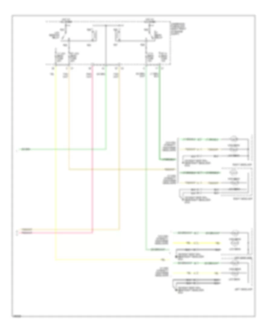
EXTERIOR LIGHTS
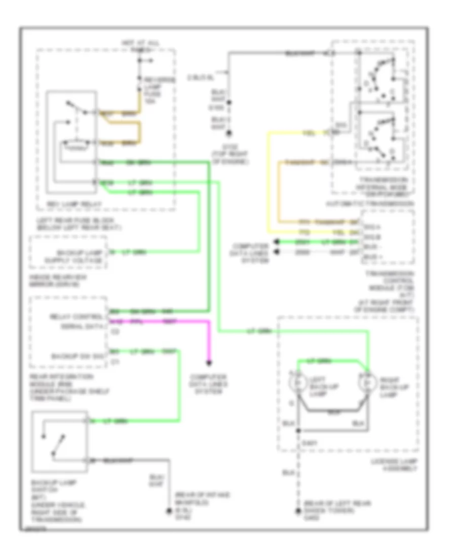
Back-up Lamps Wiring Diagram for Cadillac CTS V 2007
List of elements for Back-up Lamps Wiring Diagram for Cadillac CTS V 2007:
- (rear of intake manifold) (6.0l) g142
- (rear of left rear shock tower) g402
- 2.8l/3.6l
- A12
- Automatic transmission
- Backup lamp switch (m/t) (under vehicle, right side of transmission)
- Backup sw sig
- Bus +
- Bus -
- Computer data lines system
- G132 (top right of engine)
- Hot at all times
- Inside rearview mirror (isrvm)
- Left back-up lamp
- Left rear fuse block (below left rear seat)
- License lamp assembly
- R36
- R37
- R38
- R40
- Rear integration module (rim) (under package shelf trim panel)
- Relay control
- Rev lamp relay
- Reverse lamp fuse 10a
- Right back-up lamp
- S155
- S401
- Serial data
- Sig a
- Sig b
- Transmission control module (tcm) (a/t) (at right front of engine compt)
- Transmission internal mode switch (ims)
Exterior Lamps Wiring Diagram (1 of 2) for Cadillac CTS V 2007
List of elements for Exterior Lamps Wiring Diagram (1 of 2) for Cadillac CTS V 2007:
- (behind left kick panel) g200
- (not used)
- 5v ref
- A11
- A12
- Auto
- Bas rly
- Battery
- Bpp sig
- Brake pedal position (bpp) sensor (near top of brake pedal)
- C12
- C13
- Center high mounted stop lamp (chmsl)
- Class 2 serial data
- Computer data lines system
- Dash integration module (under right side of dash, above right closeout/ insulator panel)
- Dimming fuse 10a
- Drl low control
- Drl low ctrl
- Electronic brake control module (ebcm) (at right front corner of engine compt)
- Flasher fuse 15a
- G104 (on right body rail, near right headlamp)
- G200 (behind left kick panel)
- G402 (rear of left rear shock tower)
- Ground
- Hazard request sig
- Hazard sw sig
- Hazard sw signal
- Hazard switch
- Head
- Headlamps on sig
- Hot at all times
- Hot in run or start
- Ign 1 relay
- Interior lights system
- Left front turn signal lamp
- Left front turn signal/ fog lamp assembly
- Left license lamp
- Left turn signal voltage
- Left turn sw sig
- License lamp assembly
- Low ref
- Off
- Park
- Park lamp relay
- Park lamp rly ctrl
- Park lamp sw on sig
- Pnk
- R31
- R32
- R33
- R34
- R43
- R44
- R45
- R46
- Right front turn signal lamp
- Right front turn signal/ fog lamp assembly
- Right license lamp
- Right turn signal voltage
- Right turn sw sig
- S200
- S207
- S208
- S401
- Sp102
- Sp200 (in left front of passenger compt, under dash, above steering column)
- Strg ctls fuse 10a
- To underhood fuse block (lt park fuse) (diagram 2 of 2)
- Turn signal/ multi-function switch
- Turn signal/hazard flasher module (under dash)
- Underhood fuse block (right front of engine compt)
Exterior Lamps Wiring Diagram (2 of 2) for Cadillac CTS V 2007
List of elements for Exterior Lamps Wiring Diagram (2 of 2) for Cadillac CTS V 2007:
- (behind left kick panel)
- (below left rear seat) left rear fuse block
- (in body harness, 30 cm from c410) s415
- (in body harness, 34 cm from c411) s416
- (on right body rail, near right headlamp) g104
- (rear of right rear shock tower) g401
- (right front of engine compt) underhood fuse block
- Bas fuse 15a
- Bas relay
- Class 2 (dim)
- Class 2 serial data
- Computer data lines system
- E trailering (not used)
- From underhood fuse block (dimming fuse) (diagram 1 of 2)
- G200
- G402 (rear of left rear shock tower)
- Ground
- Horn assembly)
- Hot at all times
- Instrument panel cluster (ipc)
- Joint connector
- Left front marker lamp
- Left front park lamp
- Left headlamp (w/o automatic headlamps control leveling system)
- Left rear marker lamp
- Left rear turn signal lamp
- Left tail lamp
- Left tail lamp assembly
- Left tail/ stop lamp
- Left turn indicator
- Lights on ind
- Logic
- Lt park fuse 10a
- Message center
- Message request
- Radio
- Right front marker lamp
- Right front park lamp
- Right headlamp (w/o automatic headlamps control leveling system)
- Right rear marker lamp
- Right rear turn signal lamp
- Right tail lamp
- Right tail lamp assembly
- Right tail/ stop lamp
- Right turn indicator
- Rt park fuse 10a
- S116 (in forward lamp harness, 40 cm from right cooling fan connector)
- S201
- S24
- S25
- S26
- S27
- S405
- S406
- Turn signal on theft attempted
- W/ hid
- W/o hid
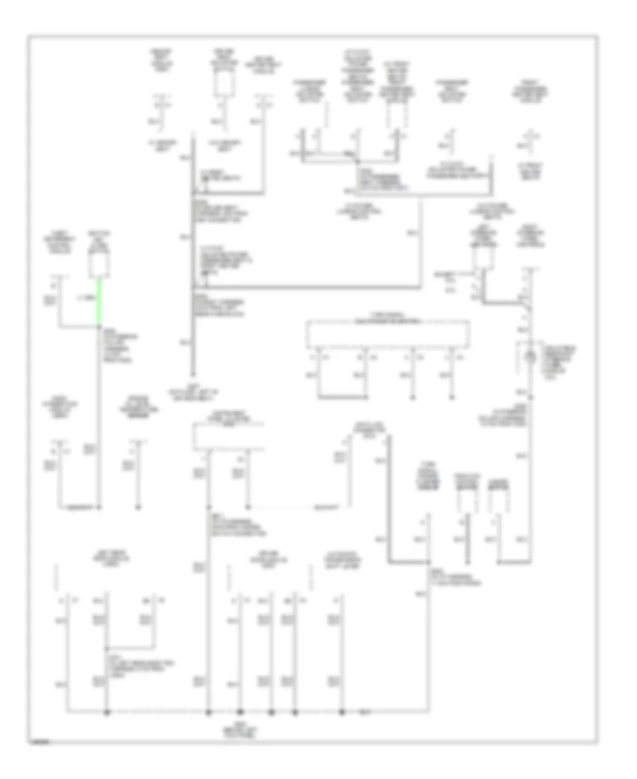
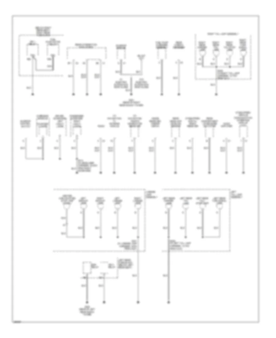
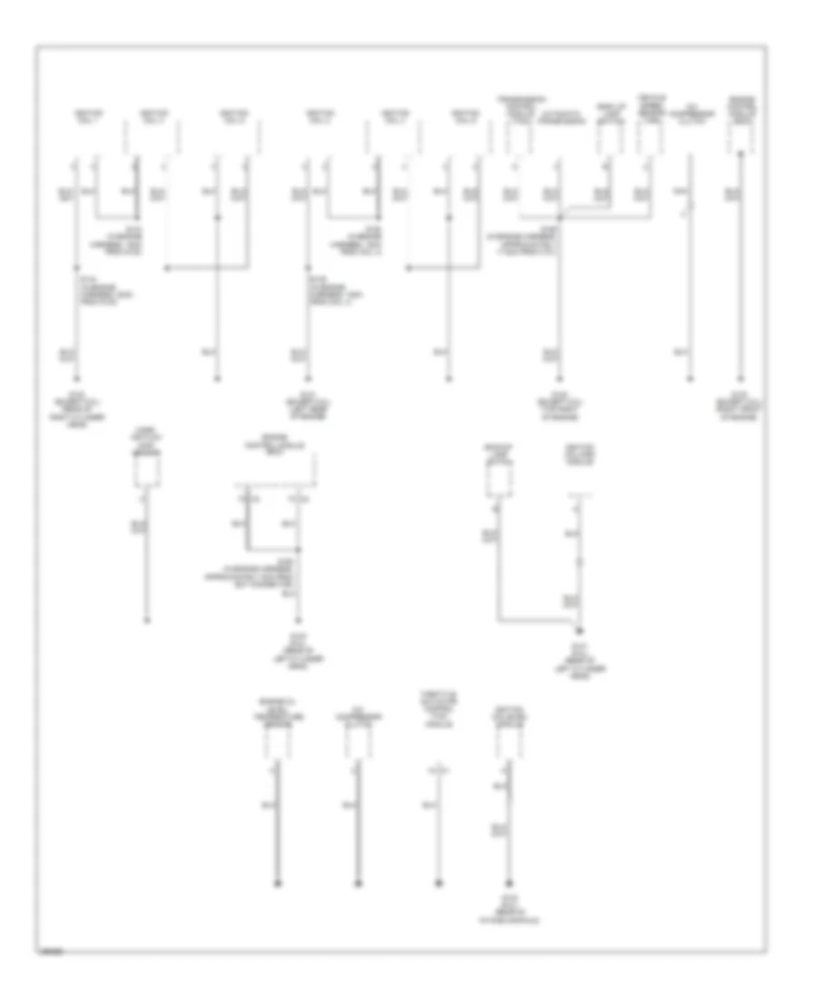
GROUND DISTRIBUTION
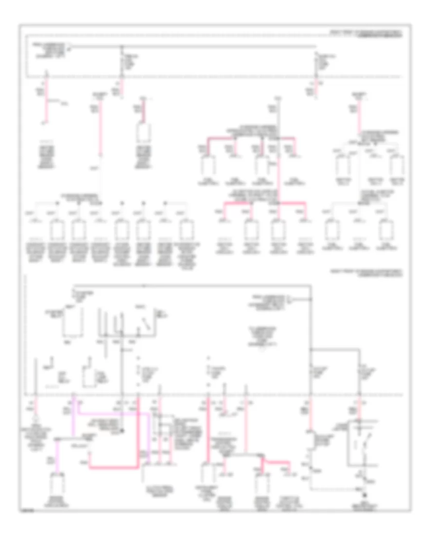
Ground Distribution Wiring Diagram (1 of 5) for Cadillac CTS V 2007
List of elements for Ground Distribution Wiring Diagram (1 of 5) for Cadillac CTS V 2007:
- (2.8l & 3.6l : right side of engine compartment) (6.0l : on inner fender wall, near battery) g105
- (6.0l: on engine block, right side, above starter) g102
- (in cellular antenna coax cable, about 31cm from g304) s309
- (on right frame rail, near abs module) g110
- B12
- Battery
- Brake fluid level switch
- Cellular antenna
- Dash integration module (dim)
- Electronic brake control module (ebcm)
- G101 (near left front strut tower)
- G303 (on right ``c" pillar)
- G304 (on left "c" pillar)
- G306 (under center console)
- Headlamp washer fluid pump
- If equipped
- Inflatable restraint sensing & diagnostic module (sdm)
- Left heated washer nozzle
- Nca
- Passenger presence system
- Rear window defogger
- Right heated washer nozzle
- Vehicle communication interface module (vcim)
- W/ high pressure headlamp washer
- W/o high pressure headlamp washer
- Washer fluid level switch
- Windshield washer fluid pump
- Windshield wiper/ washer module
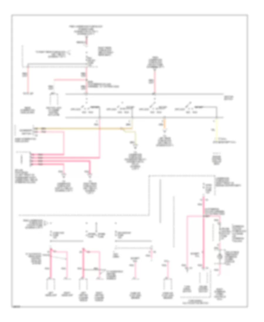
Ground Distribution Wiring Diagram (2 of 5) for Cadillac CTS V 2007
List of elements for Ground Distribution Wiring Diagram (2 of 5) for Cadillac CTS V 2007:
- (right front of engine compartment) underhood fuse block
- (w/ hid) left headlamp
- (w/ hid) right headlamp
- A/t
- Accessory relay
- Auxiliary cooling fan
- Auxiliary power outlet
- B12
- Blower motor control processor
- Cigar lighter
- Electronic prndl
- From c312)
- Front headlamp leveling sensor
- Front passenger door module (fpdm)
- G104 (on right body rail, near right headlamp)
- G201 (behind right kick panel)
- Horn assembly
- Hvac control module
- Ign 1 relay
- Left cooling fan
- Left front fog lamp
- Left front marker lamp
- Left front turn signal lamp
- Left front turn signal/ fog lamp assembly
- Left headlamp
- R16
- R35
- R46
- Right front fog lamp
- Right front marker lamp
- Right front turn signal lamp
- Right front turn signal/ fog lamp assembly
- Right headlamp
- Right rear door module (rrdm)
- S/p fan relay
- S202 (in i/p harness, 48cm from hazard switch connector)
- Trailer provisions
- W/ automatic headlamps control leveling system
- W/ hid
- W/o automatic headlamps control leveling system
- W/o hid
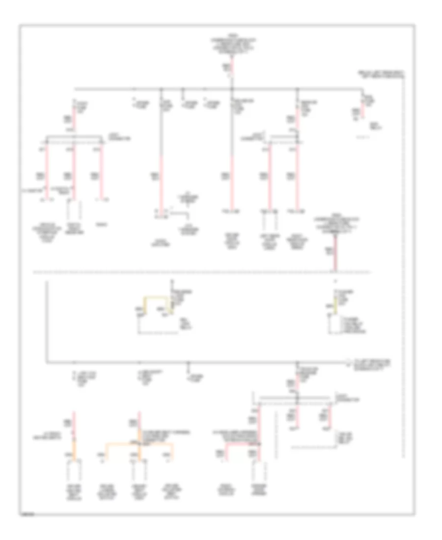
Ground Distribution Wiring Diagram (3 of 5) for Cadillac CTS V 2007
List of elements for Ground Distribution Wiring Diagram (3 of 5) for Cadillac CTS V 2007:
- (w/ 8-way adjuster power passenger seats) passenger seat adjuster switch
- (w/ front heated seats) front passenger heated seat module
- 6.0l
- Automatic transmission shift lever
- B12
- Dash integration module (dim)
- Data link connector (dlc)
- Driver door module (ddm)
- Driver heated seat module
- Driver seat adjuster switch
- Engine oil level temperature sensor
- Except 6.0l
- Front passenger heated seat module
- G200 (behind left kick panel)
- G307 (on floor, left of driver's seat)
- Hazard switch
- Ignition key alarm switch
- Inflatable restraint steering wheel module coil
- Instrument panel cluster (ipc)
- Left rear door module (lrdm)
- Left steering wheel controls
- Memory seat module (msm)
- Passenger lumbar adjuster switch
- Passenger seat adjuster switch
- Right steering wheel controls
- S200 (in i/p harness, 11.5cm from sp200)
- S201 (in i/p harness, 54cm from hazard switch connector)
- S205 (in steering column harness, 12.7cm from c202)
- S208 (in steering column harness, 12.7cm from c202)
- S305 (in body harness, 18cm from left rear fuse block)
- S350 (in driver seat harness, 8cm from msm connector)
- Theft deterrent control module
- Traction control switch
- Turn signal/ hazard flasher module
- Turn signal/ multi-function switch
- W/ 8-way adjuster power passenger seat & front heated seats
- W/ 8-way adjuster power passenger seats
- W/ front heated seats
- W/ memory seat
- W/ power lumbar control seats
- W/o memory seat
- W/o power lumbar control seats
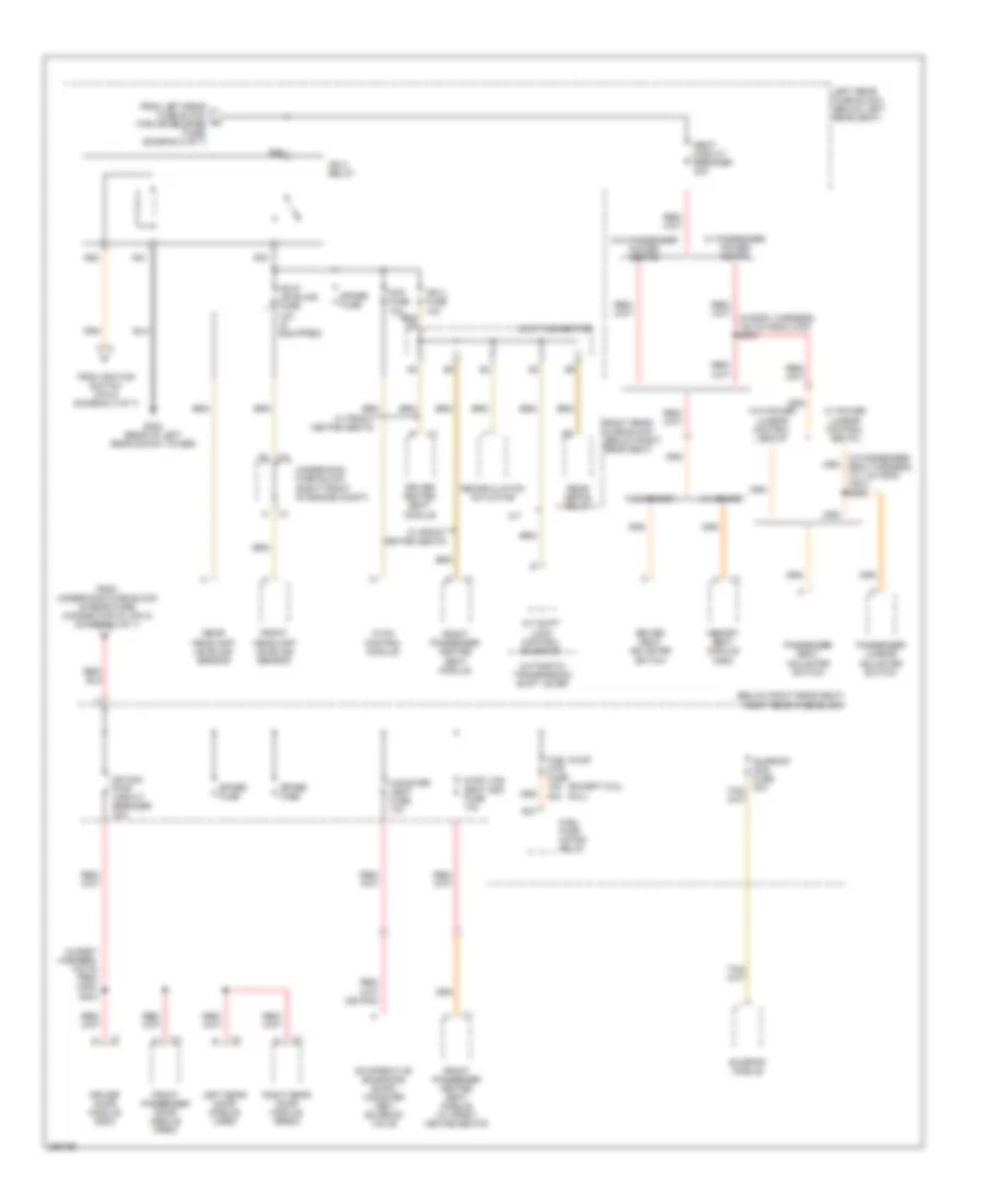
Ground Distribution Wiring Diagram (4 of 5) for Cadillac CTS V 2007
List of elements for Ground Distribution Wiring Diagram (4 of 5) for Cadillac CTS V 2007:
- (below right rear seat) right rear fuse block
- (if equipped) digital radio receiver
- (if equipped) vehicle communication interface module (vcim)
- (w/ navigation) traffic information receiver
- (w/ navigation) tv antenna module
- Audio amplifier
- B11
- Bas relay
- Center high mounted stop lamp (chmsl)
- Coil
- Courtesy lamps
- Driver sunshade
- Fuel pump & sender assembly
- Fuel pump motor relay
- G401 (rear of right rear shock tower)
- G402 (rear of left rear shock tower)
- Ign 1 relay
- Ign 3 relay
- Inside rearview mirror (isrvm)
- Left backup lamp
- Left license lamp
- Left rear fuse block (below left rear seat)
- Left rear marker lamp
- Left rear tail lamp
- Left rear tail/ stop lamp
- Left rear turn signal lamp
- Left tail lamp assembly
- Left vanity lamps
- License lamp assembly
- Nca
- Overhead console
- Passenger sunshade
- R21
- R25
- R36
- Radio
- Rear compartment lid release actuator
- Rear headlamp leveling sensor
- Rear integration module (rim)
- Rear window defogger
- Right backup lamp
- Right license lamp
- Right rear marker lamp
- Right rear tail lamp
- Right rear tail/stop lamp
- Right rear turn signal lamp
- Right tail lamp assembly
- Right vanity lamps
- S401 (in license lamp harness, 40cm from c421)
- S405 (in left tail lamp harness, 12.7cm from c410)
- S406 (in right tail lamp harness, 12.7cm from c411)
- Sunroof control switch
- Sunroof module
- Sunshade)
- W/ electric sliding sun roof glass
- W/o electric sliding sun roof glass
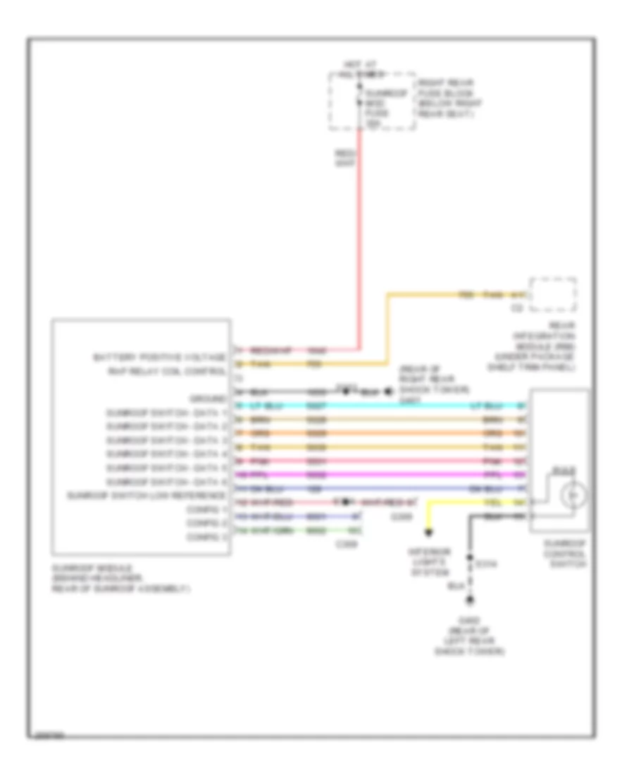
Ground Distribution Wiring Diagram (5 of 5) for Cadillac CTS V 2007
List of elements for Ground Distribution Wiring Diagram (5 of 5) for Cadillac CTS V 2007:
- A/c compressor clutch
- Automatic transmission
- Back up lamp switch
- Backup lamp switch
- Engine control module (ecm)
- Engine oil level/ temperature sensor
- G130 (except 6.0l) (rear of right cylinder head)
- G131 (except 6.0l) (left rear of engine)
- G132 (except 6.0l) (top right of engine)
- G133 (except 6.0l) (right front of engine)
- G140 (6.0l) (rear of left cylinder head)
- G141 (6.0l) (rear of left cylinder head)
- G142 (6.0l) (rear of intake manifold)
- Ignition coil 1
- Ignition coil 2
- Ignition coil 3
- Ignition coil 4
- Ignition coil 5
- Ignition coil 6
- Ignition coil/even module
- Ignition coil/odd module
- Mass air flow (maf) sensor
- Nca
- S143 (in engine harness, 15cm from g130)
- S144 (in engine harness, 20cm from g130)
- S149 (in engine harness, 15cm from coil 4)
- S150 (in engine harness, 15cm from coil 4)
- S155 (in engine harness, approximately 17.5cm from c101)
- S160 (in engine harness, approximately 8cm from ect connector)
- Throttle actuator control (tac) module
- Transmission control module (tcm)
- Vehicle speed sensor (vss)
HEADLIGHTS
Headlights Wiring Diagram (1 of 2) for Cadillac CTS V 2007
List of elements for Headlights Wiring Diagram (1 of 2) for Cadillac CTS V 2007:
- (behind left kick panel) g200
- (in left front of passenger compt, under dash, above steering column) splice pack sp200
- (in steering wheel control harness, 15.2 cm from c208) (m/t) s210
- 6 spd m/t
- A11
- A12
- Ambient light sens sig
- Auto
- B c2
- Class 2 (dim)
- Class 2 serial data
- Coil sply volt ctrl
- Computer data lines system
- Dash integration module (dim) (under right side of dash, above right closeout/insulator panel)
- E10
- F11
- F12
- F13
- F15
- Flash to pass signal
- Flash to pass switch signal
- Fog lamp fuse 15a
- Fog lamp relay
- Fog lamp rly ctrl
- Front fog lamp ind
- Front fog lamp switch
- Ft fog lamp sw sig
- G104 (on right body rail, near right headlamp)
- Head
- Headlamp on signal
- Headlamp relay control
- Hi beam rly ctrl
- High beam ind
- Hot at all times
- Hot in run or start
- Hvac control module (behind center of dash, below radio)
- Instrument panel cluster (ipc)
- J c4
- K c1
- Left front fog lamp
- Left front turn signal/ fog lamp assembly
- Lo beam rly control
- Logic
- Low
- Low reference
- Lt sunload sens sig
- M/t
- Nca
- Off
- Others
- Park
- Park lamp sw on sig
- Right front fog lamp
- Right front turn signal/ fog lamp assembly
- Rt sunload sens sig
- S201
- S208
- Sentinal delay
- Sunload sensor (top center of i/p, on defrost grill)
- Turn signal/ multifunction switch
- Underhood fuse block (right front of engine compt)
Headlights Wiring Diagram (2 of 2) for Cadillac CTS V 2007
List of elements for Headlights Wiring Diagram (2 of 2) for Cadillac CTS V 2007:
- (on right body rail, near right headlamp) g104
- Hi beam relay
- High beam
- Hot at all times
- Left headlamp
- Low beam
- Low beam/hid relay
- Lt hi beam fuse 10a
- Lt low beam fuse 20a
- R23
- R24
- R25
- R26
- R27
- R28
- R29
- R30
- Right headlamp
- Rt hi beam fuse 10a
- Rt low beam fuse 20a
- Underhood fuse block (right front of engine compt)
- W/ high intensity discharge headlamps
- W/o high intensity discharge headlamps
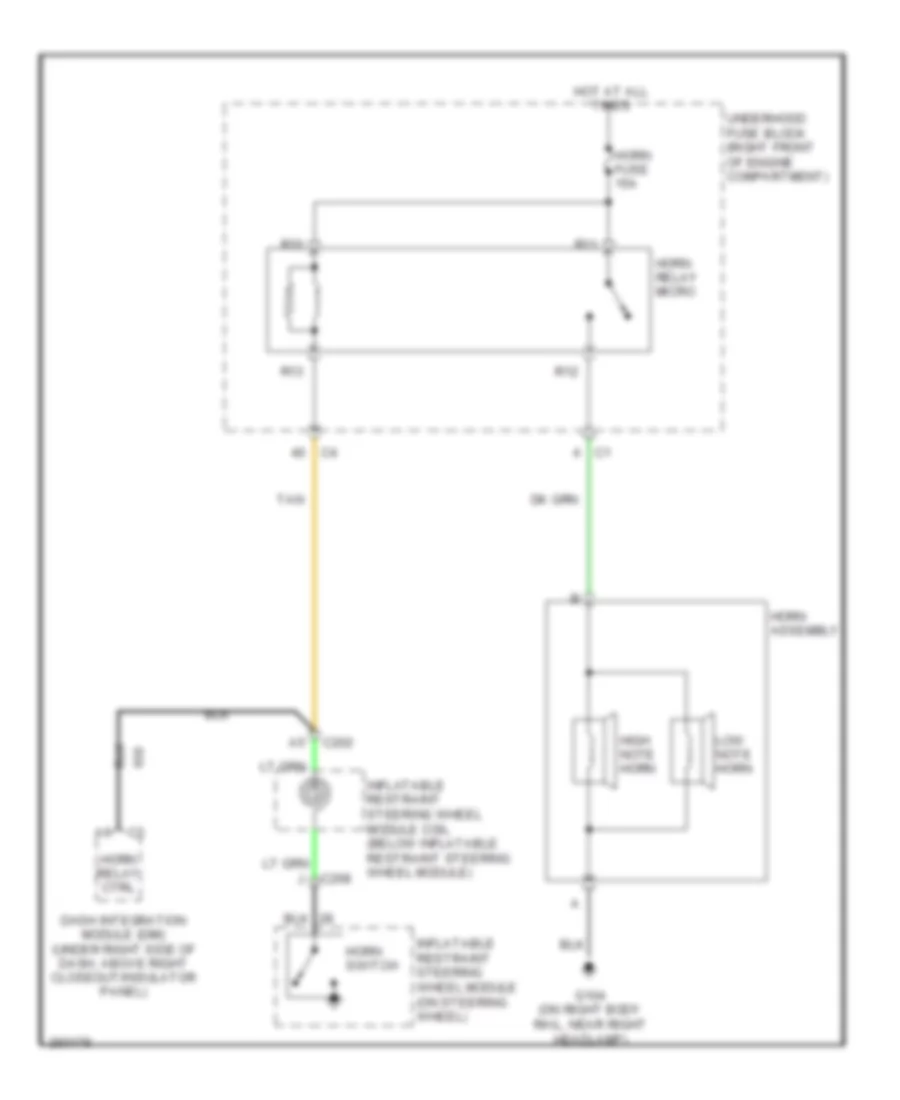
HORN
Horn Wiring Diagram for Cadillac CTS V 2007
List of elements for Horn Wiring Diagram for Cadillac CTS V 2007:
- C202
- C208
- Dash integration module (dim) (under right side of dash, above right closeout/insulator panel)
- G104 (on right body rail, near right headlamp)
- High note horn
- Horn assembly
- Horn fuse 15a
- Horn relay ctrl
- Horn relay micro
- Horn switch
- Hot at all times
- Inflatable restraint steering wheel module (on steering wheel)
- Inflatable restraint steering wheel module coil (below inflatable restraint steering wheel module)
- Low note horn
- R10
- R11
- R12
- R13
- Tan
- Underhood fuse block (right front of engine compartment)
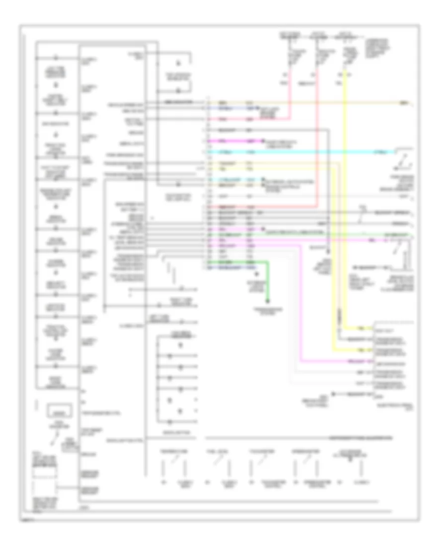
INSTRUMENT CLUSTER
Instrument Cluster Wiring Diagram (1 of 2) for Cadillac CTS V 2007
List of elements for Instrument Cluster Wiring Diagram (1 of 2) for Cadillac CTS V 2007:
- (6.0l) left driver information center (dic)
- (not used)
- 6.0l
- Abs ind sig
- Abs indicator
- Acc volt
- Anti-lock brakes system
- Backlighting
- Backlighting ctrl
- Battery (+)
- Brake fluid level switch (on brake fluid reservoir)
- Break indicator
- Charge indicator
- Class 2
- Class 2 (dim)
- Class 2 (ebcm)
- Class 2 (ecm)
- Class 2 (rim)
- Class 2 (sdm)
- Computer data lines system
- Cruise indicator
- Ecm/tcm fuse 10a
- Elec prndl fuse 10a
- Electronic prndl (a/t)
- Eng speed sig
- Engine controls system
- Engine coolant temperature indicator
- Exterior lights system
- Fasten safety belt indicator
- Front fog lamps indicator
- Fuel level
- G101 (near left front strut tower)
- G200 (behind left kick panel)
- G201 (behind right kick panel)
- Gnd
- Ground
- Ground ground steering wheel ctrl sig serial data
- High beam indicator
- Hot at all times
- Hot in acc or run
- Hot in run or start
- Ignition 1 voltage
- Instrument panel cluster (ipc)
- Led dimming sig
- Left turn indicator
- Level sens sig
- Lights on indicator
- Logic
- Low engine oil pressure ind
- Low tire pressure indicator
- Malfunction ind lamp (mil)
- Message request
- Oil temp sens sig
- Park brake sw sig
- Park brake switch (on park brake assembly)
- Pnk
- Right driver information center (dic) (6.0l)
- Right turn indicator
- S201
- Security indicator
- Serial data
- Sir indicator
- Speedometer
- Speedometer control
- Sport mode indicator
- Tachometer
- Tachometer control
- Tap un/tap down sw enable sig
- Tap up/down enable ind
- Tcm/ipc fuse 15a
- Temperature
- Traction control off indicator
- Transmission range sw sig a
- Transmission range sw sig b
- Transmission range sw sig c
- Transmission range sw sig p
- Transmissions system
- Trip reset sw sig
- Trip reset switch
- Trip/ odometer
- Trip/odometer ctrl
- Underhood fuse block (right front of engine compt)
- Vehicle speed sig
- Wait to start indicator (not used)
- Winter mode indicator
Instrument Cluster Wiring Diagram (2 of 2) for Cadillac CTS V 2007
List of elements for Instrument Cluster Wiring Diagram (2 of 2) for Cadillac CTS V 2007:
- (in engine harness, 20 cm from pcm) (3.6l/2.8l) s140
- (in fuel tank harness, 40 cm from c420) s400
- (or 231)
- (or 2705)
- (or 2755)
- (or tan)
- 2.8l/3.6l
- 5 volt reference 1
- 6.0l
- Back
- C202
- C208
- Clear dic sig
- Clr
- Computer data lines system
- Dic back sig
- Engine control module (ecm) (2.8l/3.6l: front of right valve cover) (6.0l: on front right valve cover)
- Engine controls system
- Engine oil level/ temperature sensor (6.0l)
- Engine oil pressure (eop) sensor (2.8l/3.6l: in oil filter housing) (6.0l: on top rear of engine)
- Engine speed sig
- Fuel level sens sig
- Fuel level sensor
- Fuel pump & sender assembly (in fuel tank)
- G200 (behind left kick panel)
- Ground
- Inflatable restraint steering wheel module coil (below inflatable restraint steering wheel module)
- Info
- Information dn sw sig
- Information up sw sig
- Left steering wheel controls
- Logic
- Low reference
- Message center
- Message request
- Oil lvl sw sig
- Oil pressure sw sig
- Radio
- S148 (3.6l/2.8l) (in engine harness under throttle body, 11.5 cm towards right)
- S156 (3.6l/2.8l) (in engine harness, approximately 24 cm from ebcm connector)
- S201
- Scroll dic sig
- Secondary fuel sender assembly (under vehicle, in fuel tank)
- Serial data
- Steering wheel control assembly
- Switch 1
- Switch 2
- Switch 3
- Switch 4
- Tan
- Tft sens sig
- Transmission fluid temperature (tft) sensor (m/t) (right rear of transmission assembly)
- Tune/sel
- Vehicle speed sig
- Vehicle speed signal
- W/ infotainment system
INTERIOR LIGHTS
Courtesy Lamps Wiring Diagram (1 of 2) for Cadillac CTS V 2007
List of elements for Courtesy Lamps Wiring Diagram (1 of 2) for Cadillac CTS V 2007:
- 5v reference
- A11
- A12
- B10
- C2 g
- Class 2 serial data
- Computer data lines system
- Courtesy lamp switch
- Courtesy lps on signal
- Dash integration module (under right side of dash, above right closeout/ insulator panel)
- Dim/ aldl fuse 10a
- Dimmer sw low reference
- Driver door latch assembly (at rear of driver door)
- Driver door module (on left door, under door trim)
- Driver door open sw sig
- Front passenger door latch assembly (at rear of front passenger door)
- Front passenger door module (on right front door, under door trim panel)
- Front passenger door sw sig
- G402 (rear of left rear shock tower)
- Ground
- Hot at all times
- I/p lamps dimmer switch
- Instrument illumination circuit
- Left courtesy/reading lamp
- Left rear door latch assembly (at rear of left rear door)
- Left rear door module (on left rear door, under door trim panel)
- Left rear door open sw sig
- Overhead console
- Right courtesy/reading lamp
- Right rear door latch assembly (at rear of right rear door)
- Right rear door module (on right rear door, under door trim panel)
- Right rear door open sw sig
- S314
- Tan
- Underhood fuse block (right front of engine compartment)
Courtesy Lamps Wiring Diagram (2 of 2) for Cadillac CTS V 2007
List of elements for Courtesy Lamps Wiring Diagram (2 of 2) for Cadillac CTS V 2007:
- (in headliner harness, 39.5 cm from c305) s312
- (in headliner harness, 69.5 cm from c305) s319
- (part of lid release actuator) rear compartment lid release actuator
- A10
- A12
- B10
- B12
- Class 2 serial data
- Computer data lines system
- Courtesy lamp ctrl
- Courtesy lp ctrl
- Courtesy lp relay ctrl
- Courtesy lp voltage
- Driver sunshade
- Driver vanity lamps
- Fd1
- Fd2
- G402 (rear of left rear shock tower)
- Hot at all times
- Int lamp relay
- Interior lamp fuse 10a
- Joint connector
- Left footwell courtesy lamp
- Left front door courtesy lamp
- Lid ajar sw signal
- Nca
- Passenger sunshade
- Passenger vanity lamps
- R16
- R17
- R18
- R20
- Rear compartment courtesy lamp
- Rear dome lamp
- Rear integration module (under package shelf trim panel)
- Right footwell courtesy lamp
- Right front door courtesy lamp
- Right rear fuse block (below right rear seat)
- S10
- S11
- S314
- Trunk diode
Instrument Illumination Wiring Diagram (1 of 2) for Cadillac CTS V 2007
List of elements for Instrument Illumination Wiring Diagram (1 of 2) for Cadillac CTS V 2007:
- (in i/p harness, 47 cm from hazard switch connector) s203
- 5 volt reference
- A11
- A12
- Auto head
- Automatic transmission shift lever
- B12
- Backlight lamps ctrl
- Battery
- Class 2 serial data
- Computer data lines system
- Control power output
- Dash integration module (under right side of dash, above right closeout/insulator panel)
- Dim/ aldl fuse 10a
- Dimmer switch signal
- Dimming fuse 10a
- Driver door lock switch
- Driver door module (on left door, under door trim panel)
- Driver door switch assembly (ddsa)
- Driver dr mod fuse 10a
- Electronic prndl (a/t)
- G200 (behind left kick panel)
- G201 (behind right kick panel)
- G402 (rear of left rear shock tower)
- Ground
- Hot at all times
- I/p dimmer switch
- Illumination lamp
- Inc dim
- Instrument panel cluster (ipc)
- Joint connector s13
- Led dimming signal
- Left rear fuse block (below left rear seat)
- Low reference
- Memory/ personalization function switch
- Off
- Overhead console
- Park
- Park lamp relay
- Park lamp sw on sig
- Park lp rly ctrl
- Psgr dr mod fuse 10a
- R31
- R32
- R33
- R34
- Rear compartment lid release switch
- Rear dr mod fuse 15a
- Right rear fuse block (below right rear seat)
- S12
- S13
- S14
- S208
- S308
- S314
- S321 (in headliner harness, 32.5 cm from dome lamp)
- S501 (in driver door trim harness, 24 cm from driver door lock switch)
- S502 (in driver door trim harness, 14.5 cm from ddsa)
- Serial data
- Sunroof control switch
- Turn signal/ multi-function switch
- Underhood fuse block (right front of engine compartment)
Instrument Illumination Wiring Diagram (2 of 2) for Cadillac CTS V 2007
List of elements for Instrument Illumination Wiring Diagram (2 of 2) for Cadillac CTS V 2007:
- (in front passenger door trim harness, 24.5 cm from door lock switch) s601
- 6.0l
- A12
- B12
- Backlight lamps ctrl
- Battery
- Computer data lines system
- Dimming fuse 2a
- Except 6.0l
- Front passenger door lock switch
- Front passenger door module (on right front door, under door trim panel)
- Front passenger window switch
- Fuse block (steering column) (at base of steering column)
- G200 (behind left kick panel)
- G201 (behind right kick panel)
- Ground
- Hazard switch
- Illumi- nation lamp
- Inflatable restraint steering wheel module coil (below inflatable restraint steering wheel module)
- Left rear door module (on left rear door, under door trim panel)
- Left rear window switch
- Left steering wheel controls
- Right rear door module (on right rear door, under door trim panel)
- Right rear window switch
- Right steering wheel controls
- S200
- S208
- S602 (in front passenger door trim harness, 8.5 cm from window switch)
- S701
- Serial data
MEMORY SYSTEMS
Memory Mirrors Wiring Diagram (1 of 2) for Cadillac CTS V 2007
List of elements for Memory Mirrors Wiring Diagram (1 of 2) for Cadillac CTS V 2007:
- 5v ref
- 5v reference
- A12
- B11
- B12
- Backlight lamps control
- Battery
- Class 2 serial data
- Computer data lines system
- Door locks system
- Driver door module (on left front door, under door trim panel)
- Driver door switch assembly (ddsa)
- Driver dr mod fuse 10a
- Driver outside rearview mirror
- Exit
- G200 (behind left kick panel)
- Gnd
- Ground
- Ground rtn
- Horiz motor
- Horiz pos sensor
- Horiz posit sensor
- Hot at all times
- Interior lights system
- Left
- Left horiz
- Left rear fuse block (below left rear seat)
- Logic
- Low ref
- Low reference
- Memory 1 switch signal
- Memory 2 switch signal
- Memory/personalization function switch
- Mirror mtr down ctrl
- Mirror mtr left ctrl
- Mirror mtr right ctrl
- Mirror mtr up ctrl
- Nca
- Outside rearview mirror switch
- Right
- Right horiz
- S502 (in left front door trim harness, 14.5 cm from ddsa)
- Sel left
- Sel right
- Vert down
- Vert motor
- Vert pos sensor
- Vert up
- Vertical posit sensor
Memory Mirrors Wiring Diagram (2 of 2) for Cadillac CTS V 2007
List of elements for Memory Mirrors Wiring Diagram (2 of 2) for Cadillac CTS V 2007:
- 5v feed
- 5v reference
- 5v rtn
- A12
- B12
- Battery
- Class 2 serial data
- Computer data lines system
- Dr mod pwr circuit breaker 30a
- Front passenger door module (on right front door, under door trim panel)
- G201 (behind right kick panel)
- Ground
- Horiz motor
- Horiz pos sensor
- Horizontal posit sensor
- Hot at all times
- Left horiz
- Low reference
- Mirror mtr down ctrl
- Mirror mtr left ctrl
- Mirror mtr right ctrl
- Mirror mtr up ctrl
- Passenger outside rearview mirror
- Psgr dr mod fuse 10a
- Right horiz
- Right rear fuse block (below right rear seat)
- S303
- Vert down
- Vert motor
- Vert pos sensor
- Vert up
- Vertical posit sensor
Memory Seat Wiring Diagram (1 of 2) for Cadillac CTS V 2007
List of elements for Memory Seat Wiring Diagram (1 of 2) for Cadillac CTS V 2007:
- 5 volt reference
- Battery positive voltage
- Class 2 serial data
- Dr lumbar horiz posit sens signal
- Driver seat adjuster switch
- E10
- E11
- E12
- E13
- E14
- E15
- E16
- F10
- F11
- F12
- F13
- F14
- F15
- F16 c2
- Front vertical down
- Front vertical motor down control
- Front vertical motor up control
- Front vertical up
- G307 (on floor, left of driver's seat)
- Ground
- Horizontal forward
- Horizontal forward switch signal
- Horizontal motor forward ctrl
- Horizontal motor rearward control
- Horizontal rearward
- Horizontal rearward switch signal
- Hot at all times
- Left rear fuse block (below left rear seat)
- Low reference
- Lumbar forward switch signal
- Lumbar rearward switch signal
- Lumber motor forward control
- Lumber motor rearward control
- Mem/adapt seat fuse 10a
- Memory seat module (msm) (under driver's seat)
- Pnk
- Rear vertical down
- Rear vertical motor down control
- Rear vertical motor up control
- Rear vertical posit sens signal
- Rear vertical up
- Recline back switch signal
- Recline forward
- Recline forward switch signal
- Recline motor forward control
- Recline motor rearward control
- Recline posit sens signal
- Recline rearward
- S350 (w/ heated seats)
- S351
- Seat circuit breaker 30a
- Seat horiz posit sensor signal
- Tan
- Vertical down switch signal
- Vertical posit sens signal
- Vertical up switch signal
Memory Seat Wiring Diagram (2 of 2) for Cadillac CTS V 2007
List of elements for Memory Seat Wiring Diagram (2 of 2) for Cadillac CTS V 2007:
- (in driver seat harness, 10 cm from seat horizontal position sensor) s348
- (in left front seat harness, 15 cm from driver seat rear vertical position sensor) s349
- (under driver seat) driver seat front vertical motor
- (under driver seat) driver seat horizontal motor
- (under driver seat) driver seat rear vertical motor
- (under driver seat) driver seat recline motor
- Backlight lamps control
- Class 2 serial data
- Door locks system
- Driver door module (on left front door, under door trim panel)
- Driver door switch assembly (ddsa)
- Driver lumbar adjuster switch
- Driver lumbar horizontal motor assembly (in left front seat back)
- Driver seat front vertical position sensor (under driver seat, on back of motor)
- Driver seat horizontal position sensor (under driver seat, on back of motor)
- Driver seat rear vertical position sensor (under driver seat, on back of motor)
- Driver seat recline position sensor (under driver seat, on back of motor)
- Exit
- Forward
- Gnd
- Ground
- Interior lights system
- Memory 1 sw signal
- Memory 1 switch signal
- Memory 2 sw signal
- Memory 2 switch signal
- Memory/personalization function switch
- Nca
- Not used
- Pnk
- Rearward
- S502 (in left front door trim harness, 14.5 cm from ddsa)
- Sp300 (in passenger compartment, near left side of driver's seat)
- Tan
NAVIGATION
Navigation Wiring Diagram for Cadillac CTS V 2007
List of elements for Navigation Wiring Diagram for Cadillac CTS V 2007:
- (coaxial cable)
- (or bare)
- Audio amplifier (rear of left strut tower)
- Audio fuse 10a
- Bare
- Battery
- Class 2 serial data
- Computer data lines system
- Drain wire
- G402 (rear of left rear shock tower)
- Gps signal
- Ground
- Hot at all times
- Infotainment system
- Inside rearview mirror (isrvm)
- Joint connector
- Left rear fuse block (below left rear seat)
- Mic out feed
- Mic out return
- Microphone low ref
- Microphone sig
- Nav voice in (-)
- Nav voice out (+)
- Navigation antenna (in center of dash)
- Navigation audio sig (+)
- Navigation audio sig (-)
- Pnk
- Radio
- S18
- Sig
- Vehicle communication interface module (vcim) (in rear compartment, behind right strut tower)
- Vehicle communication system
- W/o vehicle communication system
POWER DISTRIBUTION
Power Distribution Wiring Diagram (1 of 7) for Cadillac CTS V 2007
List of elements for Power Distribution Wiring Diagram (1 of 7) for Cadillac CTS V 2007:
- (6.0l)
- (except 6.0l)
- (in engine harness, 15 cm from coil 1) s145
- (in engine harness, approximately 20 cm from underhood fuse block) s161
- (in fuel injector harness, 10 cm from c121) s151
- (in ignition coil/module harness, on left valve cover, 5 cm from c131) s163
- (not used)
- (right front of engine compartment) underhood fuse block
- 6.0l
- A/t
- Battery
- Blower fuse 40a
- Blower relay
- C1 g
- C2 a12
- Ccp fuse 10a
- Dash integration module (dim)
- Data link connector (dlc)
- Dim/ aldl fuse 10a
- Ecm fuse 15a
- Ecm/tcm fuse 10a
- Engine control module (ecm)
- Evaporative emissions (evap) canister purge solenoid valve
- Except 6.0l
- Flasher fuse 15a
- Fuel injector
- Fusible link
- Generator
- Heated oxygen sensor (ho2s) bank 1 sensor 2
- Heated oxygen sensor (ho2s) bank 2 sensor 2
- Hi fan fuse 30a
- Hi speed fan relay
- Hvac control module
- Ignition coil 1
- Ignition coil 3
- Ignition coil 5
- Ignition coil/ module 1
- Ignition coil/ module 3
- Ignition coil/ module 5
- Ignition coil/ module 7
- Instrument panel cluster (ipc)
- Left rear fuse block (below left rear seat)
- Low fan fuse 30a
- Low speed fan relay
- Main relay
- Odd inj/ coil fuse 20a
- Pnk
- Post o2 fuse 15a
- Pusher fan relay
- R14
- R19
- R20
- R39
- R40
- R47
- R48
- R49
- R50
- R51
- R52
- Reverse lock out solenoid
- S/p fan relay
- S173
- Skip shift solenoid
- Spare fuse
- Starter
- Theft deterrent control module
- To underhood fuse block (horn relay) (diagram 2 of 7)
- To underhood fuse block (pre 2/cam fuse) (diagram 3 of 7)
- Tos fuse 10a
- Trailer provisions
- Transmission control module (tcm)
- Turn signal/ hazard flasher module
- Vehicle speed sensor (vss)
- Volt check fuse 10a
Power Distribution Wiring Diagram (2 of 7) for Cadillac CTS V 2007
List of elements for Power Distribution Wiring Diagram (2 of 7) for Cadillac CTS V 2007:
- (6.0l)
- (except 6.0l)
- (in engine harness, approximately 8 cm from ebcm connector) s130
- (right front of engine compartment) underhood fuse block
- Abs fuse 50a
- Accessory relay
- Comp clutch fuse 10a
- Comp clutch relay
- Elec prndl fuse 10a
- Electronic brake control module (ebcm)
- Electronic prndl (a/t)
- Engine control module (ecm)
- Fog lamp fuse 15a
- Fog lamp relay
- From ignition switch (pin 2) (diagram 4 of 7)
- From underhood fuse block a (main relay) (diagram 1 of 7)
- G104 (on right body rail, near right headlamp)
- Hdlp wash circuit breaker 30a
- Hdlp washer relay
- High beam relay
- Horn fuse 15a
- Horn relay
- Ign sw fuse 10a
- L rear fuse 60a
- Low beam/ hid relay
- Park lamp relay
- R rear fuse 60a
- R10
- R11
- R24
- R28
- R32
- R35
- R36
- R37
- R38
- R56
- R68
- Spare fuse
- Theft deterrent control module
- Theft fuse 7.5a
- To ignition switch (pin 6) (diagram 4 of 7)
- To left rear fuse block (driver dr mod fuse) (diagram 5 of 7)
- To left rear fuse block (pusher fan fuse) (diagram 5 of 7)
- To right rear fuse block (dr mod pwr circuit breaker) (diagram 6 of 7)
- To right rear fuse block (rim/ign sw fuse) (diagram 4 of 7)
- To underhood fuse block (i/p out let fuse) (diagram 3 of 7)
- Transmission control module (tcm) (a/t)
- Windshield wiper/ washer module
- Windshield wiper/ washer switch
- Wpr mod fuse 30a
- Wpr sw fuse 10a
Power Distribution Wiring Diagram (3 of 7) for Cadillac CTS V 2007
List of elements for Power Distribution Wiring Diagram (3 of 7) for Cadillac CTS V 2007:
- (accessory relay) (diagram 2 of 7)
- (in engine harness, 15 cm from coil 5) s142
- (in engine harness, 24.5 cm from ect sensor) s146
- (in engine harness, approximately 20 cm from underhood fuse block) s162
- (in fuel injector harness, 10 cm from c121) s152
- (in ignition coil/module harness, on right valve cover, 5 cm from c132) s164
- (on right body rail, near right headlamp) g104
- (right front of engine compartment) underhood fuse block
- 6.0l
- A/t
- Auxiliary power outlet
- Camshaft actuator solenoid exhaust bank 1
- Camshaft actuator solenoid exhaust bank 2
- Camshaft actuator solenoid intake bank 1
- Camshaft actuator solenoid intake bank 2
- Cigar lighter
- Clutch pedal position (cpp) sensor
- Cmp clu relay
- Engine control module (ecm)
- Evaporative emission (evap) canister purge solenoid valve
- Even inj/ coil fuse 20a
- Except 6.0l
- Fog lamp relay
- From ignition switch (via splice pack sp200) (pin 8) (diagram 4 of 7)
- From underhood fuse block b (ecm fuse) (diagram 1 of 7)
- From underhood fuse block h
- Fuel injector 2
- Fuel injector 4
- Fuel injector 6
- Fuel injector 8
- G201 (behind right kick panel)
- Heated oxygen sensor (ho2s) bank 1 sensor 1
- Heated oxygen sensor (ho2s) bank 2 sensor 1
- Htr vlv/ cltch fuse 10a
- I/p outlet fuse 20a
- Ign 1 relay
- Ignition coil 2
- Ignition coil 4
- Ignition coil 6
- Ignition coil/ module 2
- Ignition coil/ module 4
- Ignition coil/ module 6
- Ignition coil/ module 8
- Instrument panel cluster (ipc)
- Intake manifold runner control (imrc) solenoid
- Outlet fuse 30a
- Pnk
- Pre o2/ cam fuse 15a
- R43
- R44
- R45
- R46
- R55
- R63
- R64
- S202
- S308
- Splice pack sp200 (in left front of passenger compt, under dash, above steering column)
- Starter fuse 30a
- Starter relay
- Tcm/ipc fuse 15a
- Throttle actuator control (tac) module
- To underhood fuse block (wash noz fuse) (diagram 4 of 7)
- Transmission control module (tcm)
Power Distribution Wiring Diagram (4 of 7) for Cadillac CTS V 2007
List of elements for Power Distribution Wiring Diagram (4 of 7) for Cadillac CTS V 2007:
- (6.0l)
- (except 6.0l)
- (in steering column harness, 12.7 cm from c202) s207
- (not used)
- 6.0l
- A11
- Acc
- Accessory
- Cruise control switch
- Cruise control switch fuse 2a
- Dash integration module (dim)
- Engine control module (ecm)
- Except 6.0l
- From underhood fuse block (ign sw fuse) (diagram 2 of 7)
- From underhood fuse block (r rear fuse) (connector c3, pin 1) (diagram 2 of 7)
- From underhood fuse block (tcm/ipc fuse) (diagram 3 of 7)
- Ign mod/maf fuse 15a
- Ignition 1
- Ignition lock cylinder control actuator
- Ignition switch
- Inflatable restraint steering wheel module coil
- Left headlamp
- Left heated washer nozzle
- Mass air flow (maf) sensor
- Off/lock
- Pnk
- Rear integration module (rim)
- Right headlamp
- Right heated washer nozzle
- Right rear fuse block (below right rear seat)
- Right steering wheel controls (6.0l)
- Rim/ ign sw fuse 10a
- Run
- S206 (in steering column harness, 12.7 cm from c202)
- Spare fuse
- Splice pack sp200 (in left front of passenger compt, under dash, above steering column)
- Start
- Steering column fuse block (at base of steering column)
- Strg ctls fuse 10a
- To left rear fuse block (ign 3 relay) (diagram 6 of 7)
- To right rear fuse block (ign 1 relay) (diagram 7 of 7)
- To underhood fuse block (accessory relay) (connector c4, pin 37) (diagram 2 of 7)
- To underhood fuse block (cmp clu relay) (diagram 3 of 7)
- Turn signal switch
- Turn signal/ multifunction switch
- Underhood fuse block (right front of engine compartment)
- W/ automatic headlamps control leveling system
- W/ windshield heated washer nozzels
- Wash noz fuse 10a
Power Distribution Wiring Diagram (5 of 7) for Cadillac CTS V 2007
List of elements for Power Distribution Wiring Diagram (5 of 7) for Cadillac CTS V 2007:
- (below left rear seat) left rear fuse block
- (in driver seat harness, 8 cm from msm connector) s351
- (in headliner harness, 22.5 cm from radio antenna module) s313
- A12
- Amp fuse 30a
- Audio amplifier
- Audio fuse 10a
- Bas fuse 15a
- Bas relay
- Digital radio receiver
- Driver adjuster seat switch
- Driver door module (ddm)
- Driver dr mod fuse 10a
- Driver heated seat module
- Driver lumbar adjuster switch
- F11
- From underhood fuse block (l rear fuse) (connector c2, pin 1) (diagram 2 of 7)
- From underhood fuse block (l rear fuse, 60a) (connector c2, pin 2) (diagram 2 of 7)
- Garage door opener
- Joint connector
- L frt htd seat mod fuse 10a
- Left rear door module (lrdm)
- Mem/adapt seat fuse 10a
- Memory seat module (msm)
- Pusher fan fuse 30a
- Pusher fan relay (trailer provisions)
- R31
- R32
- R36
- R37
- Radio
- Radio antenna module
- Rear dr mod fuse 15a
- Rev lamp relay
- Reverse lamp fuse 10a
- Right rear door module (rrdm)
- S12
- S13
- S14
- S15
- S17
- S18
- S19
- S20
- S21
- S22
- S23
- Spare fuse
- To left rear fuse block (ign 3 relay) (diagram 6 of 7)
- Trk dr rel sol relay
- Trunk dr release fuse 10a
- Vehicle communication interface module (vcim)
- W/ 7 speaker system
- W/ digital radio
- W/ front heated seats
- W/ onstar
- W/o 7 speaker system
Power Distribution Wiring Diagram (6 of 7) for Cadillac CTS V 2007
List of elements for Power Distribution Wiring Diagram (6 of 7) for Cadillac CTS V 2007:
- (below right rear seat) right rear fuse block
- (except 6.0l) (6.0l)
- (in body harness, 108 cm from c700) s304
- (in body harness, 108 cm from c800) s303
- (in passenger seat harness, 12.7 cm from c307) s352
- A/t
- A/t shift lock control solenoid
- Automatic transmission shift lever
- Canister vent fuse 10a
- Ccp fuse 10a
- Dr mod pwr circuit breaker 30a
- Driver door module (ddm)
- Driver heated seat module
- Driver seat adjuster switch
- Evaporative emissions (evap) canister vent solenoid valve
- From ignition switch (pin 5) (diagram 4 of 7)
- From left rear fuse block (trk dr release fuse) (diagram 5 of 7)
- From underhood fuse block (r rear fuse) (connector c3, pin 2) (diagram 2 of 7)
- Front headlamp leveling sensor
- Front passenger door module (fpdm)
- Front passenger heated seat module
- Front passenger heated seat module (w/ front heated seats)
- Fuel pump motor relay
- Fuel pump mtr fuse 15a 20a
- G402 (rear of left rear shock tower)
- Hdlp leveling fuse 10a (if equipped)
- Hvac control module
- Ign 3 fuse 10a
- Ign 3 relay
- Joint connector
- Left rear door module (lrdm)
- Left rear fuse block (below left rear seat)
- Memory seat module (msm)
- Passenger lumbar adjuster switch
- Passenger seat adjuster switch
- R frt htd seat mod fuse 10a
- R21
- R22
- R23
- R25
- R37
- Rear defog relay
- Rear headlamp leveling sensor
- Recirculation actuator
- Right rear door module (rrdm)
- Right rear fuse block (below right rear seat)
- Seat circuit breaker 30a
- Spare fuse
- Sunroof module
- Underhood fuse block (right front of engine compt)
- W/ front heated seats
- W/ memory
- W/ passenger power seats
- W/ power lumbar control seats
- W/o memory
- W/o passenger power seats
- W/o power lumbar control seats
Power Distribution Wiring Diagram (7 of 7) for Cadillac CTS V 2007
List of elements for Power Distribution Wiring Diagram (7 of 7) for Cadillac CTS V 2007:
- (in i/p harness, 11.5 cm from sp200) s200
- A11
- A12
- Abs fuse 10a
- Air bag fuse 10a
- Electronic brake control module (ebcm)
- From ignition switch (via splice pack sp200, pin 9) (diagram 4 of 7)
- From right rear fuse block (rim/ign sw fuse) (diagram 4 of 7)
- Front passenger door module (fpdm)
- G401 (rear of right rear shock tower)
- If equipped
- Ign 1 relay
- Ignition lock cylinder control actuator
- Ignition switch
- Inflatable restraint sensing & diagnostic module (sdm)
- Inside rear view mirror
- Int lamp relay
- Interior lamp fuse 10a
- Joint connector
- Pnk
- Psgr dr mod fuse 10a
- R16
- R17
- R21
- R22
- R23
- R25
- R31
- R32
- Rear defog fuse 40a
- Rear defog relay
- Rear fog lamp fuse 10a
- Rear fog lamp relay
- Rear integration module
- Rear integration module (rim)
- Right rear fuse block (below right rear seat)
- Rim fuse 10a
- Rim/ign sw fuse 10a
- S21
- S22
- S23
- Spare fuse
POWER DOOR LOCKS
Power Door Locks Wiring Diagram (1 of 2) for Cadillac CTS V 2007
List of elements for Power Door Locks Wiring Diagram (1 of 2) for Cadillac CTS V 2007:
- (behind left kick panel) g200
- (behind right kick panel) g201
- A12
- B10
- B11
- B12
- Backlight lamps ctrl
- Battery
- Class 2 serial data
- Computer data lines system
- Door ajar signal
- Door ajar sw signal
- Door ajar switch signal
- Door key unlock switch signal
- Door lock act lock ctrl
- Door lock act unlk ctrl
- Door lock sw lock sig
- Door lock sw unlock sig
- Door open signal
- Door open switch signal
- Dr mod pwr circuit breaker 30a
- Driver door latch assembly
- Driver door module (on left door, under door trim panel)
- Driver door open sw sig
- Driver door switch assembly (ddsa)
- Driver dr key sw unlk sig
- Driver dr mod fuse 10a
- Front passenger door latch assembly
- Front passenger door module (on right front door, under door trim panel)
- Gnd
- Ground
- Hot at all times
- Interior lights system
- Joint connector
- Keyless entry/ tire pressure antenna signal
- Left rear fuse block (below left rear seat)
- Memory seat switch
- Psgr dr mod fuse 10a
- Radio antenna module (above headliner, near rear window)
- Rear compartment lid release switch
- Rear dr mod fuse 15a
- Rear glass antenna
- Rfa grid
- Right rear fuse block (below right rear seat)
- S12
- S13
- S14
- S20
- S22
- S303
- S313
- S502 (in left front door trim harness, 14.5 cm from ddsa)
- Tan
- Trunk dr release fuse 10a
Power Door Locks Wiring Diagram (2 of 2) for Cadillac CTS V 2007
List of elements for Power Door Locks Wiring Diagram (2 of 2) for Cadillac CTS V 2007:
- (behind left kick panel) g200
- (behind right kick panel) g201
- A12
- Ajar
- B10
- B12
- Backlight lamps control
- Backlight lamps ctrl
- Battery
- Class 2 serial data
- Computer data lines system
- Door act lock ctrl
- Door ajar switch signal
- Door lock act lock ctrl
- Door lock act unlk ctrl
- Door open switch signal
- Driver door lock switch
- Front passenger door lock switch
- Front passenger window switch
- Ground
- Interior lights system
- Left rear door latch assembly
- Left rear door module (under door trim panel)
- Lock
- Open
- Right rear door latch assembly
- Right rear door module (on right rear door, under door trim panel)
- S602 (in right front door trim harness, 8.5 cm from window switch)
- S701
- Tan
- Unlock
POWER MIRRORS
Automatic Day/Night Mirror Wiring Diagram for Cadillac CTS V 2007
List of elements for Automatic Day/Night Mirror Wiring Diagram for Cadillac CTS V 2007:
- (or bare)
- (rear of left rear shock tower) g402
- A12
- Backup lamp voltage
- Bare
- Class 2 serial data
- Computer data lines system
- Drain wire
- Exterior lights system
- Ground
- Hot at all times
- Hot in run or start
- Ignition voltage
- Inside rearview mirror (isrvm)
- Joint connector
- Key pad sig
- Led signal
- Left rear fuse block (below left rear seat)
- Microphone
- Microphone low ref
- Microphone sig
- Passenger presence system/static supression module
- Pnk
- Pnk s21
- Psir off
- Psir off ind
- Psir on
- Psir on ind
- R36
- R37
- R38
- R40
- Radio
- Rear integration module (under package shelf trim panel)
- Rev lamp relay
- Reverse lamp ctrl
- Reverse lamp fuse 10a
- Right rear fuse block (below right rear seat)
- Rim fuse 10a
- S23
- Vehicle communication interface module (vcim) (w/ onstar) (in rear compt, behind right strut tower)
- W/ onstar
- W/o onstar
Power Mirrors Wiring Diagram for Cadillac CTS V 2007
List of elements for Power Mirrors Wiring Diagram for Cadillac CTS V 2007:
- 5v ref
- A12
- B11
- B12
- Battery
- Class 2 serial data
- Computer data lines system
- Defogger system
- Door locks system
- Down
- Dr mod pwr circuit breaker 30a
- Driver door module (on left front door, under door trim panel)
- Driver door switch assembly (ddsa)
- Driver dr mod fuse 10a
- Driver mir hor pos sens sig
- Driver mir ver pos sens sig
- Driver outside rearview mirror
- Front passenger door module (fpdm) (on right front door, under door trim panel)
- G200 (behind left kick panel)
- G201 (behind right kick panel)
- Ground
- Horiz motor
- Hot at all times
- Left
- Left mirror mtr-down
- Left mirror mtr-left
- Left mirror mtr-right
- Left mirror mtr-up
- Left rear fuse block (below left rear seat)
- Logic
- Low ref
- Outside rearview mirror switch
- Pass mir hor pos sens sig
- Pass mir ver pos sens sig
- Passenger outside rearview mirror
- Psgr dr mod fuse 10a
- Right
- Right mirror motor-up
- Right mirror mtr-down
- Right mirror mtr-left
- Right mirror mtr-right
- Right rear fuse block (below right rear seat)
- S303
- S502 (in left front door trim harness, 14.5 cm from ddsa)
- Sel left
- Sel right
- Vert motor
POWER SEATS
Heated Seats Wiring Diagram for Cadillac CTS V 2007
List of elements for Heated Seats Wiring Diagram for Cadillac CTS V 2007:
- (on floor, left of driver's seat) g307
- A11
- A12
- B12
- Battery
- Class 2 serial data
- Computer data lines system
- Dash integration module (dim) (under right side of dash, above right closeout/insulator panel)
- Driver heated seat
- Driver heated seat status
- Driver heated seat switch
- Driver high/low signal
- Driver seat back heated seat element
- Driver seat front cushion heated seat element
- Driver seat rear cushion heated seat element
- Driver's heated seat module (under driver's seat)
- E10
- Front passenger heated seat
- Front passenger seat back heated seat element
- Front passenger seat cushion front heated seat element
- Front passenger seat cushion rear heated seat element
- Ground
- Heated seat element control
- Heated seat element voltage
- Heated seat high/low signal
- Heated seat module status sig
- Heated seat module status signal
- Heated seat sensor low ref
- Heated seat temp sens signal
- Hot at all times
- Hot w/ ign 3 relay energized
- Hvac control module (behind center of dash, below radio)
- Ign 3 fuse 10a
- Ignition 3 voltage
- Joint connector
- Left rear fuse block (below left rear seat)
- Logic
- Lt frt htd seat mod fuse 10a
- Passenger heated seat status
- Passenger heated seat switch
- Passenger high/low signal
- Passenger's heated seat module (under passenger's seat)
- Pnk
- R frt htd seat mod fuse 10a
- Radio
- Rear integration module (under package shelf trim panel)
- Right rear fuse block (below right rear seat)
- S305 (w/o power lumbar)
- S320 (w/ power lumbar)
- S350
- Seat temp sensor low ref
- Seat temp sensor signal
- Thermistor
Passenger"s Lumbar Wiring Diagram for Cadillac CTS V 2007
List of elements for Passenger"s Lumbar Wiring Diagram for Cadillac CTS V 2007:
- Forward
- G307 (on floor, left of driver's seat)
- Hot at all times
- Left rear fuse block (below left rear seat)
- Passenger lumbar adjuster switch
- Passenger lumbar horizontal motor (in right front seat back)
- Rearward
- S320
- S352
- Seat circuit breaker 30a
Power Seats Wiring Diagram for Cadillac CTS V 2007
List of elements for Power Seats Wiring Diagram for Cadillac CTS V 2007:
- (on floor, left of driver's seat) g307
- (under passenger seat)
- Aft
- Battery
- Down
- Driver seat adjuster switch
- Driver seat front vertical motor (under driver seat)
- Driver seat horizontal motor (under driver seat)
- Driver seat rear vertical motor (under driver seat)
- Driver seat recline motor (under driver seat)
- Front vertical down
- Front vertical up
- Fwd
- Gnd
- Horizontal forward
- Horizontal rearward
- Hot at all times
- Left rear fuse block (below left rear seat)
- Passenger seat adjuster switch
- Passenger seat front vertical motor (under passenger seat)
- Passenger seat horizontal motor (under passenger seat)
- Passenger seat rear vertical motor (under passenger seat)
- Passenger seat recline motor
- Rear vertical down
- Rear vertical up
- Recline forward
- Recline rearward
- S304 (w/ passenger power seats)
- S305 (w/o power lumbar)
- S320 (w/ power lumbar)
- S350 (w/ heated seats)
- S352 (w/ power lumbar)
- Seat circuit breaker 30a
- Tan
POWER TOP/SUNROOF
Power Top/Sunroof Wiring Diagram for Cadillac CTS V 2007
List of elements for Power Top/Sunroof Wiring Diagram for Cadillac CTS V 2007:
- (rear of right rear shock tower) g401
- Battery positive voltage
- Bulb
- C309
- Config 1
- Config 2
- Config 3
- G309
- G402 (rear of left rear shock tower)
- Ground
- Hot at all times
- Interior lights system
- Pnk
- Rap relay coil control
- Rear integration module (rim) (under package shelf trim panel)
- Right rear fuse block (below right rear seat)
- S314
- S353
- S354
- Sunroof control switch
- Sunroof mod fuse 30a
- Sunroof module (behind headliner, rear of sunroof assembly)
- Sunroof switch - data 1
- Sunroof switch - data 2
- Sunroof switch - data 3
- Sunroof switch - data 4
- Sunroof switch - data 5
- Sunroof switch - data 6
- Sunroof switch low reference
- Tan
POWER WINDOWS
Power Windows Wiring Diagram (1 of 2) for Cadillac CTS V 2007
List of elements for Power Windows Wiring Diagram (1 of 2) for Cadillac CTS V 2007:
- A12
- B11
- B12
- Battery
- Battery positive voltage
- Class 2 serial data
- Computer data lines system
- Door locks system
- Down control
- Down sig
- Dr mod pwr c/b circuit breaker 30a
- Driver door module (on left door, under door trim)
- Driver dr mod fuse 10a
- Driver window motor
- Express signal
- Front passenger door module (on right front door, under door trim panel)
- Front passenger window motor
- Front passenger window switch
- G200 (behind left kick panel)
- G201 (behind right kick panel)
- Ground
- High speed serial data
- Hot at all times
- Interior lights system
- Joint connector
- Left rear fuse block (below left rear seat)
- Low reference
- Low speed serial data
- Pnk
- Psgr dr mod fuse 10a
- Rear dr mod fuse 15a
- Right rear fuse block (below right rear seat)
- S12
- S13
- S14
- S303
- S602 (in right front door trim harness, 8.5 cm from window switch)
- Up control
- Up signal
Power Windows Wiring Diagram (2 of 2) for Cadillac CTS V 2007
List of elements for Power Windows Wiring Diagram (2 of 2) for Cadillac CTS V 2007:
- (on right rear door, under door trim panel) right rear door module
- A12
- B12
- Backlights lamps ctrl
- Battery
- Class 2 serial data
- Computer data lines system
- Door locks system
- Down control
- Down signal
- Driver door switch assembly (ddsa)
- Drv window down sig
- Drv window express sig
- Drv window up sig
- Express signal
- Front passenger down sig
- Front passenger express sig
- Front passenger up sig
- G200 (behind left kick panel)
- G201 (behind right kick panel)
- Ground
- Left rear door module (under door trim panel)
- Left rear window motor
- Left rear window switch
- Logic
- Lr window down sig
- Lr window express sig
- Lr window up sig
- Right rear window motor
- Right rear window switch
- Rr window down sig
- Rr window express sig
- Rr window up sig
- S701
- Up control
- Up signal
- Window lock out
RADIO
7-Speaker System Wiring Diagram, Base (1 of 2) for Cadillac CTS V 2007
List of elements for 7-Speaker System Wiring Diagram, Base (1 of 2) for Cadillac CTS V 2007:
- (in center of dash) (w/o gps) navigation antenna
- (not used)
- (or 1782)
- (or 655)
- (or bare)
- (or coax)
- (rear of left rear shock tower) g402
- Am/fm antenna signal
- Amp fuse 30a
- Antenna signal
- Audio fuse 10a
- Bare
- Battery
- Cellular microphone sig
- Cellular microphone signal
- Class 2 serial data
- Coil 1
- Coil 2
- Computer data lines system
- Drain wire
- Fm antenna signal
- Fm composite signal
- Gps sig
- Ground
- Hot at all times
- Info down switch signal
- Information up sw signal
- Infotainment system
- Inside rearview mirror (isrvm)
- Instrument cluster system
- Joint connector
- Keyless entry/tire pressure antenna signal
- Left "a" pillar tweeter speaker
- Left front door speaker
- Left low audio signal (+)
- Left low audio signal (-)
- Left rear fuse block (below left rear seat)
- Microphone low ref
- Modem ground
- Modem receive
- Modem transmit
- Pnk
- Radio
- Radio antenna module (above headliner, near rear window)
- Radio front glass antenna
- Radio rear glass antenna (in rear window glass)
- Rear subwoofer speaker
- Remote radio ctrl voltage
- Rfa rear glass antenna (top of rear window)
- Right low audio signal (+)
- Right low audio signal (-)
- S18
- S22
- S313
- Steering wheel ctrls sig
- Tan
- Vehicle communication system
- Vehicle speed signal
7-Speaker System Wiring Diagram, Base (2 of 2) for Cadillac CTS V 2007
List of elements for 7-Speaker System Wiring Diagram, Base (2 of 2) for Cadillac CTS V 2007:
- (rear of left rear shock tower) g402
- A10
- A11
- Audio amplifier (rear of left strut tower)
- B10
- B11
- B12
- Bare
- Battery
- Cellular telephone voice low ref
- Cellular telephone voice signal
- Class 2 serial data
- Computer data lines system
- Drain wire
- Dw sig
- G200 (behind left kick panel)
- Ground
- Inflatable restraint steering wheel module coil (below inflatable restraint steering wheel module)
- Interior lights system
- Left front midrange spkr out (+)
- Left front midrange spkr out (-)
- Left front tweeter spkr out (+)
- Left front tweeter spkr out (-)
- Left low level audio sig (+)
- Left low level audio sig (-)
- Left rear door speaker
- Left rear midrange spkr out (+)
- Left rear midrange spkr out (-)
- Left steering wheel controls
- Low ref
- Mic low ref
- Mic sig
- Pnk
- Right "a" pillar tweeter speaker
- Right fnt midrange spkr out (+)
- Right fnt midrange spkr out (-)
- Right front door speaker
- Right front tweeter spkr out (+)
- Right front tweeter spkr out (-)
- Right low level audio sig (+)
- Right low level audio sig (-)
- Right rear door speaker
- Right rear midrange spkr out (+)
- Right rear midrange spkr out (-)
- Right steering wheel controls
- S208
- Steering wheel control assembly (2.8l & 3.6l)
- Subwoofer spkr coil 1 out (+)
- Subwoofer spkr coil 1 out (-)
- Subwoofer spkr coil 2 out (+)
- Subwoofer spkr coil 2 out (-)
- Sw 1
- Sw 2
- Sw 3
- Sw 4
- Sw audio
- Sw vox
- Tan
- Up sig
- Vehicle communication interface module (vcim) (in rear compartment, behind right strut tower)
- Voice signal
7-Speaker System Wiring Diagram, Luxury (1 of 2) for Cadillac CTS V 2007
List of elements for 7-Speaker System Wiring Diagram, Luxury (1 of 2) for Cadillac CTS V 2007:
- (in center of dash) (w/o gps) navigation antenna
- (not used)
- (or 1782)
- (or 655)
- (or bare)
- (or coax)
- (rear of left rear shock tower) g402
- Am/fm antenna signal
- Amp fuse 30a
- Antenna assembly
- Antenna signal
- Audio common
- Audio fuse 10a
- Bare
- Battery
- Cellular microphone sig
- Cellular microphone signal
- Class 2 serial data
- Coax
- Coil 1
- Coil 2
- Computer data lines system
- Digital radio antenna
- Digital radio receiver (left side of rear package shelf)
- Drain wire
- Fm antenna signal
- Fm composite signal
- Gps sig
- Ground
- Hot at all times
- Info down switch signal
- Information up sw signal
- Infotainment system
- Inside rearview mirror (isrvm)
- Instrument cluster system
- Joint connector
- Keyless entry/tire pressure antenna signal
- L audio sig(+)
- Left audio signal (+)
- Left audio signal (-)
- Left audio signal(+)
- Left rear fuse block (below left rear seat)
- Microphone low ref
- Modem ground
- Modem receive
- Modem transmit
- Pnk
- R audio sig(+)
- Radio
- Radio antenna module (above headliner, near rear window)
- Radio front glass antenna
- Radio rear glass antenna (in rear window glass)
- Rear subwoofer speaker
- Remote radio ctrl voltage
- Rfa rear glass antenna (top of rear window)
- Right audio signal (+)
- Right audio signal (-)
- S18
- S19
- S22
- S313
- Serial data
- Steering wheel ctrls sig
- Tan
- Vehicle communication system
- Vehicle speed signal
7-Speaker System Wiring Diagram, Luxury (2 of 2) for Cadillac CTS V 2007
List of elements for 7-Speaker System Wiring Diagram, Luxury (2 of 2) for Cadillac CTS V 2007:
- (rear of left rear shock tower) g402
- A10
- A11
- Audio amplifier (rear of left strut tower)
- B10
- B11
- B12
- Bare
- Battery
- Cellular telephone voice low ref
- Cellular telephone voice signal
- Class 2 serial data
- Computer data lines system
- Dn sw
- Drain wire
- G200 (behind left kick panel)
- Ground
- Inflatable restraint steering wheel module coil (below inflatable restraint steering wheel module)
- Interior lights system
- Left "a" pillar tweeter speaker
- Left front door speaker
- Left front midrange spkr out (+)
- Left front midrange spkr out (-)
- Left front tweeter spkr out (+)
- Left front tweeter spkr out (-)
- Left low level audio sig (+)
- Left low level audio sig (-)
- Left rear door speaker
- Left rear midrange spkr out (+)
- Left rear midrange spkr out (-)
- Left steering wheel controls
- Low ref
- Mic low ref
- Mic out
- Pnk
- Right "a" pillar tweeter speaker
- Right fnt midrange spkr out (+)
- Right fnt midrange spkr out (-)
- Right front door speaker
- Right front tweeter spkr out (+)
- Right front tweeter spkr out (-)
- Right low level audio sig (+)
- Right low level audio sig (-)
- Right rear door speaker
- Right rear midrange spkr out (+)
- Right rear midrange spkr out (-)
- Right steering wheel controls
- S208
- Steering wheel control assembly (2.8l & 3.6l)
- Subwoofer spkr coil 1 out (+)
- Subwoofer spkr coil 1 out (-)
- Subwoofer spkr coil 2 out (+)
- Subwoofer spkr coil 2 out (-)
- Sw1 audio
- Sw2 vox
- Tan
- Up sw
- Vehicle communication interface module (vcim) (in rear compartment, behind right strut tower)
- Voice signal
8-Speaker System Wiring Diagram, Base (1 of 2) for Cadillac CTS V 2007
List of elements for 8-Speaker System Wiring Diagram, Base (1 of 2) for Cadillac CTS V 2007:
- (in center of dash) (w/o gps) navigation antenna
- (not used)
- (or 1782)
- (or 655)
- (or bare)
- (or coax)
- Am/fm antenna signal
- Amp fuse 30a
- Antenna signal
- Audio fuse 10a
- Bare
- Battery
- Cellular microphone sig
- Cellular microphone signal
- Class 2 serial data
- Computer data lines system
- Drain wire
- Fm antenna signal
- Fm composite signal
- G402 (rear of left rear shock tower)
- Gps sig
- Ground
- Hot at all times
- Info down switch signal
- Information up sw signal
- Infotainment system
- Inside rearview mirror (isrvm)
- Instrument cluster system
- Joint connector
- Keyless entry/tire pressure antenna signal
- Left "a" pillar tweeter speaker
- Left front door speaker
- Left low audio signal (+)
- Left low audio signal (-)
- Left rear fuse block (below left rear seat)
- Microphone low ref
- Modem ground
- Modem receive
- Modem transmit
- Navigation audio sig (+)
- Navigation audio sig (-)
- Pnk
- Radio
- Radio antenna module (above headliner, near rear window)
- Radio front glass antenna
- Radio rear glass antenna (in rear window glass)
- Remote radio ctrl voltage
- Rfa rear glass antenna (top of rear window)
- Right low audio signal (+)
- Right low audio signal (-)
- S18
- S22
- S313
- Splice pack sp300 (in passenger compt, near left side of driver's seat)
- Steering wheel ctrls sig
- Tan
- Vehicle communication system
- Vehicle speed signal
8-Speaker System Wiring Diagram, Base (2 of 2) for Cadillac CTS V 2007
List of elements for 8-Speaker System Wiring Diagram, Base (2 of 2) for Cadillac CTS V 2007:
- (rear of left rear shock tower)
- A10
- A11
- A12
- Audio amplifier (rear of left strut tower)
- B10
- B11
- B12
- Bare
- Battery
- Cellular telephone voice low ref
- Cellular telephone voice sig
- Class 2 serial data
- Computer data lines system
- Dn sig
- Drain wire
- Front center speaker
- Front center spkr out (+)
- Front center spkr out (-)
- G200 (behind left kick panel)
- G402
- Ground
- Inflatable restraint steering wheel module coil (below inflatable restraint steering wheel module)
- Interior lights system
- Left front tweeter spkr out (+)
- Left front tweeter spkr out (-)
- Left low lvl audio sig (+)
- Left low lvl audio sig (-)
- Left rear door speaker
- Left rear midrange spkr out (+)
- Left rear midrange spkr out (-)
- Left steering wheel controls
- Low ref
- Mic low ref
- Mic sig
- Navigation audio sig (+)
- Navigation audio sig (-)
- Noise compensation microphone (in overhead console)
- Noise microphone voltage
- Pnk
- Rear subwoofer speaker
- Rear subwoofer spkr out (+)
- Rear subwoofer spkr out (-)
- Right "a" pillar speaker tweeter
- Right front door speaker
- Right front tweeter spkr out (+)
- Right front tweeter spkr out (-)
- Right low lvl audio sig (+)
- Right low lvl audio sig (-)
- Right rear door speaker
- Right rear midrange spkr (+)
- Right rear midrange spkr (-)
- Right steering wheel controls
- S208
- Splice pack sp300 (in passenger compt, near left side of driver's seat)
- Steering wheel control assembly (2.8l & 3.6l)
- Sw1 audio
- Sw2 vox
- Tan
- Up sig
- Vehicle communication interface module (vcim) (in rear compartment, behind right strut tower)
- Voice signal
8-Speaker System Wiring Diagram, Luxury (1 of 2) for Cadillac CTS V 2007
List of elements for 8-Speaker System Wiring Diagram, Luxury (1 of 2) for Cadillac CTS V 2007:
- (in center of dash) (w/o gps) navigation antenna
- (not used)
- (or 1782)
- (or 655)
- (or bare)
- (or coax)
- (rear of left rear shock tower)
- (rear of left rear shock tower) g402
- Am/fm antenna signal
- Amp fuse 30a
- Antenna assembly
- Antenna signal
- Audio common
- Audio fuse 10a
- Bare
- Battery
- Cellular microphone sig
- Cellular microphone signal
- Class 2 serial data
- Coax
- Computer data lines system
- Digital radio antenna
- Digital radio receiver (left side of rear package shelf)
- Drain wire
- Fm antenna signal
- Fm composite signal
- G402
- Gps sig
- Ground
- Hot at all times
- Info down switch signal
- Information up sw signal
- Infotainment system
- Inside rearview mirror (isrvm)
- Instrument cluster system
- Joint connector
- Keyless entry/tire pressure antenna signal
- L audio sig (+)
- Left "a" pillar tweeter speaker
- Left audio signal (+)
- Left front door speaker
- Left low audio signal (+)
- Left low audio signal (-)
- Left rear fuse block (below left rear seat)
- Microphone low ref
- Modem ground
- Modem receive
- Modem transmit
- Navigation audio sig (+)
- Navigation audio sig (-)
- Pnk
- R audio sig (+)
- Radio
- Radio antenna module (above headliner, near rear window)
- Radio front glass antenna
- Radio rear glass antenna (in rear window glass)
- Remote radio ctrl voltage
- Rfa rear glass antenna (top of rear window)
- Right audio signal (+)
- Right low audio signal (+)
- Right low audio signal (-)
- S18
- S19
- S22
- S313
- Serial data
- Splice pack sp300 (in passenger compt, near left side of driver's seat)
- Steering wheel ctrls sig
- Tan
- Vehicle communication system
- Vehicle speed signal
8-Speaker System Wiring Diagram, Luxury (2 of 2) for Cadillac CTS V 2007
List of elements for 8-Speaker System Wiring Diagram, Luxury (2 of 2) for Cadillac CTS V 2007:
- (rear of left rear shock tower)
- A10
- A11
- A12
- Audio amplifier (rear of left strut tower)
- B10
- B11
- B12
- Bare
- Battery
- Cellular telephone voice low ref
- Cellular telephone voice sig
- Class 2 serial data
- Computer data lines system
- Drain wire
- Dw sig
- Front center spkr out (+)
- Front center spkr out (-)
- Front speaker center
- G200 (behind left kick panel)
- G402
- Ground
- Inflatable restraint steering wheel module coil (below inflatable restraint steering wheel module)
- Interior lights system
- Left front tweeter spkr out (+)
- Left front tweeter spkr out (-)
- Left low lvl audio sig (+)
- Left low lvl audio sig (-)
- Left rear door speaker
- Left rear midrange spkr out (+)
- Left rear midrange spkr out (-)
- Left steering wheel controls
- Low ref
- Mic low ref
- Mic sig
- Navigation audio sig (+)
- Navigation audio sig (-)
- Noise compensation microphone (in overhead console)
- Noise microphone voltage
- Pnk
- Rear subwoofer speaker
- Rear subwoofer speaker out (+)
- Rear subwoofer speaker out (-)
- Right "a" pillar tweeter speaker
- Right front door speaker
- Right front tweeter spkr out (+)
- Right front tweeter spkr out (-)
- Right low lvl audio sig (+)
- Right low lvl audio sig (-)
- Right rear door speaker
- Right rear midrange spkr (+)
- Right rear midrange spkr (-)
- Right steering wheel controls
- S208
- Splice pack sp300 (in passenger compt, near left side of driver's seat)
- Steering wheel control assembly (2.8l & 3.6l)
- Sw1 audio
- Sw2 vox
- Tan
- Up sig
- Vehicle communication interface module (vcim) (in rear compartment, behind right strut tower)
- Voice signal
SHIFT INTERLOCK
Ignition Lock Solenoid Wiring Diagram for Cadillac CTS V 2007
List of elements for Ignition Lock Solenoid Wiring Diagram for Cadillac CTS V 2007:
- A11
- A12
- Automatic transmission shift lever
- Class 2 serial data
- Computer data lines system
- Dash integration module (under right side of dash, above right closeout/insulator panel)
- Hot at all times
- Ignition lock cyl ctrl
- Ignition lock cylinder control actuator (on steering column)
- Ignition lock cylinder control switch (closed in park)
- Right rear fuse block (below right rear seat)
- Rim/ign sw fuse 10a
- S200
- Tan
Shift Interlock Wiring Diagram for Cadillac CTS V 2007
List of elements for Shift Interlock Wiring Diagram for Cadillac CTS V 2007:
- A/t shift lock control solenoid
- A12
- Automatic transmission shift lever
- B12
- Class 2 serial data
- Computer data lines system
- G402 (rear of left rear shock tower)
- Hot at all times
- Hot in run
- Ign 3 fuse 10a
- Ign 3 relay
- Joint connector
- Left rear fuse block (below left rear seat)
- R21
- R22
- R25
- Rear integration module (under package shelf trim panel)
- Shift lock solenoid control
STARTING/CHARGING
2.8L VIN T
2.8L VIN T, Charging Wiring Diagram for Cadillac CTS V 2007
List of elements for 2.8L VIN T, Charging Wiring Diagram for Cadillac CTS V 2007:
- (right side of engine compt) g105
- Battery
- Charge indicator
- Class 2
- Class 2 serial data
- Computer data lines system
- Engine control module (ecm) (front of right valve cover)
- Fusible link
- G102
- Gen duty cycle sig
- Gen turn on sig
- Generator
- Ground distribution system
- Ign
- Instrument panel cluster (ipc)
- Logic
- Power distribution system
- Red
- Serial data class 2
- Starter
2.8L VIN T, Starting Wiring Diagram for Cadillac CTS V 2007
List of elements for 2.8L VIN T, Starting Wiring Diagram for Cadillac CTS V 2007:
- (not used)
- (on right body rail, near right headlamp) g104
- (right side of engine compt) g105
- A/t
- Acc
- Automatic transmission (a/t)
- Battery
- Charging circuit
- Clutch pedal position switch (m/t) (on clutch pedal bracket)
- Computer data lines system
- Crank
- Crank voltage
- Engine control module (ecm) (front of right valve cover)
- G102
- Ground distribution system
- Hot at all times
- Hot in run or start
- Htr vlv/ cltch fuse 10a
- Ign 1 relay
- Ignition switch
- Off/ lock
- Park/neutral signal (a/t)
- Pnk
- R43
- R44
- R45
- R46
- R63
- R64
- R65
- R66
- Red
- Run
- Serial data
- Splice pack sp200 (in right front of passenger compartment, under dash, above steering column)
- Starter
- Starter fuse 30a
- Starter relay
- Starter relay coil ctrl
- Underhood fuse block (right front of engine compartment)
3.6L VIN 7
3.6L VIN 7, Charging Wiring Diagram for Cadillac CTS V 2007
List of elements for 3.6L VIN 7, Charging Wiring Diagram for Cadillac CTS V 2007:
- (right side of engine compt) g105
- Battery
- Charge indicator
- Class 2
- Class 2 serial data
- Computer data lines system
- Engine control module (ecm) (front of right valve cover)
- Fusible link
- G102
- Gen duty cycle sig
- Gen turn on sig
- Generator
- Ground distribution system
- Ign
- Instrument panel cluster (ipc)
- Logic
- Power distribution system
- Red
- Serial data class 2
- Starter
3.6L VIN 7, Starting Wiring Diagram for Cadillac CTS V 2007
List of elements for 3.6L VIN 7, Starting Wiring Diagram for Cadillac CTS V 2007:
- (not used)
- (on right body rail, near right headlamp) g104
- (right side of engine compt) g105
- A/t
- Acc
- Automatic transmission (a/t)
- Battery
- Charging circuit
- Clutch pedal position switch (m/t) (on clutch pedal bracket)
- Computer data lines system
- Crank
- Crank voltage
- Engine control module (ecm) (front of right valve cover)
- G102
- Ground distribution system
- Hot at all times
- Hot in run or start
- Htr vlv/ cltch fuse 10a
- Ign 1 relay
- Ignition switch
- Off/ lock
- Park/neutral signal (a/t)
- Pnk
- R43
- R44
- R45
- R46
- R63
- R64
- R65
- R66
- Red
- Run
- Serial data
- Splice pack sp200 (in right front of passenger compartment, under dash, above steering column)
- Starter
- Starter fuse 30a
- Starter relay
- Starter relay coil ctrl
- Underhood fuse block (right front of engine compartment)
6.0L VIN U
6.0L VIN U, Charging Wiring Diagram for Cadillac CTS V 2007
List of elements for 6.0L VIN U, Charging Wiring Diagram for Cadillac CTS V 2007:
- (on engine block, right side, above starter) g102
- (on inner fender wall, near battery) g105
- Battery
- Charge indicator
- Class 2
- Class 2 serial data
- Computer data lines system
- Engine control module (ecm) (on front right valve cover)
- Fusible link
- Gen duty cycle sig
- Gen turn on sig
- Generator
- Ground distribution system
- Ign b+
- Instrument panel cluster (ipc)
- Logic
- Power distribution system
- Serial data class 2
- Starter
6.0L VIN U, Starting Wiring Diagram for Cadillac CTS V 2007
List of elements for 6.0L VIN U, Starting Wiring Diagram for Cadillac CTS V 2007:
- (on engine block, right side, above starter) g102
- (on inner fender wall, near battery) g105
- (on right body rail, near right headlamp) g104
- Acc
- Battery
- Charging circuit
- Clutch pedal position switch (m/t) (on clutch pedal bracket)
- Cpp switch signal
- Crank
- Crank voltage
- Engine control module (ecm) (on front right valve cover)
- Ground distribution system
- Hot at all times
- Hot in run or start
- Htr vlv/ cltch fuse 10a
- Ign 1 relay
- Ignition switch
- Off/ lock
- Pnk
- R43
- R44
- R45
- R46
- R63
- R64
- R65
- R66
- Run
- Splice pack sp200 (in left front of passenger compartment, under dash, above steering column)
- Starter
- Starter fuse 30a
- Starter relay
- Starter relay coil ctrl
- Starter relay coil voltage
- Underhood fuse block (right front of engine compartment)
SUPPLEMENTAL RESTRAINTS
Supplemental Restraints Wiring Diagram (1 of 2) for Cadillac CTS V 2007
List of elements for Supplemental Restraints Wiring Diagram (1 of 2) for Cadillac CTS V 2007:
- (right side of driver's seat) driver seat belt switch
- (right side of passenger seat) passenger seat belt switch
- Airbag fuse 10a
- Auto occupant sens
- Automatic occupant sens
- Case ground
- Computer data lines system
- Driver inflatable restraint roof rail module (above right "b" pillar)
- Driver inflatable restraint side impact module (on left side of left front seat)
- Driver inflatable restraint side impact sensing module
- Driver seat belt pretensioner (right side of driver's seat)
- G306 (under center console)
- Gnd
- Ground
- High control
- Hot in run or crank
- Ign
- Ign 1
- Ignition 1 voltage
- Inflatable restraint sensing & diagnostic module (sdm) (under center console)
- Inflatable restraint steering wheel module (on steering wheel)
- Inflatable restraint steering wheel module coil (below inflatable restraint steering wheel module)
- Inside rearview mirror
- Left seat belt switch
- Low control
- Low reference
- Nca
- Passenger inflatable restraint side impact sensing module
- Passenger presence system/static suppression module
- Pnk
- Psir off
- Psir off ind
- Psir on
- Psir on ind
- Right rear fuse block (below right rear seat)
- Right seat belt switch
- Sensor signal
- Sensor voltage
- Serial data
- Shorting bar
- Stage 1
- Stage 2
- Tan
Supplemental Restraints Wiring Diagram (2 of 2) for Cadillac CTS V 2007
List of elements for Supplemental Restraints Wiring Diagram (2 of 2) for Cadillac CTS V 2007:
- (6.0l)
- (except 6.0l)
- (in seat)
- Class 2
- Computer data lines system
- Data link connector (under left side of dash)
- Ign
- Inflatable restraint front end discriminating sensor
- Inflatable restraint i/p module (above glove box)
- Instrument panel cluster
- Logic
- Message center
- Nca
- Passenger inflatable restraint roof rail module (above right "b" pillar)
- Passenger inflatable restraint side impact module (on right side of right front seat)
- Passenger seat belt pretensioner (right side of driver's seat)
- Radio
- Serial data
- Service air bag
- Shorting bar
- Sir indicator
- Splice pack sp200 (in right front passenger compartment, under dash, above steering column)
- Splice pack sp300 (in passenger compartment, near left side of driver's seat)
- Stage 1
- Stage 2
- Underhood fuse block (right front of engine compartment)
TRANSMISSION
2.8L VIN T
2.8L VIN T, A/T Wiring Diagram (1 of 2) for Cadillac CTS V 2007
List of elements for 2.8L VIN T, A/T Wiring Diagram (1 of 2) for Cadillac CTS V 2007:
- (in engine harness, approximately 17.5 cm from c101) s155
- (partial) (under left side of dash)
- 1-2 shift sol
- 1-2 shift sol vlv
- 2-3 shift sol
- 2-3 shift sol vlv
- 4-5 shift sol
- 4-5 shift sol vlv
- A/t iss hi sig
- A/t iss lo sig
- Acc volt
- Anti-lock brakes system
- Automatic transmission
- Automatic transmission shift lever
- Bas rly ctrl
- Battery
- Data link connector
- Ecm/tcm fuse 10a
- G132 (top right of engine)
- G200 (behind left kick panel)
- G401 (rear of right rear shock tower)
- Ground
- Hi spd gmlan +
- Hi spd gmlan -
- Hot at all times
- Hot in acc or run
- Hot in run or start
- Ign 1 fuse 10a pnk
- Ign 1 relay
- Ign 1 volt
- Interior lights system
- Joint connector
- Oss sens high
- Oss sens low
- Pc sol vlv hi ctrl
- Pc sol vlv lo ctrl
- Pnk
- Power distribution system
- Pressure control solenoid valve
- R21
- R22
- R25
- Right rear fuse block (below right rear seat)
- S127
- S17
- S19
- Ser data (can) +
- Ser data (can) -
- Sol pwr feed
- Tan
- Tap up/down sw sig
- Tcc sol valve
- Tcc sol vlv ctrl
- Tcm/ipc fuse 15a
- Tft sens lo ref
- Tft sens sig
- Theft fuse 7.5a
- Transmission control module (tcm) (at right front of engine compt)
- Transmission fluid temperature sensor
- Transmission input shaft speed sensor
- Transmission output shaft speed sensor
- Trs sig a
- Trs sig b
- Trs sig c
- Trs sig p
- Underhood fuse block (right front of engine compt)
2.8L VIN T, A/T Wiring Diagram (2 of 2) for Cadillac CTS V 2007
List of elements for 2.8L VIN T, A/T Wiring Diagram (2 of 2) for Cadillac CTS V 2007:
- A11
- A12
- A13
- A14
- Automatic transmission
- B12
- Dash integration module (under right side of dash, above right closeout/ insulator panel)
- E10
- Elec prndl fuse 10a
- Electronic brake control module (ebcm) (at right front corner of engine compt)
- Electronic prndl
- Engine control module (ecm) (on front of right valve cover)
- G132 (top right of engine)
- G201 (behind right kick panel)
- Hi spd gmlan +
- Hi spd gmlan -
- Hot w/ accessory relay energized
- Hvac control module (behind center of dash, below radio)
- Inflatable restraint sensing & diagnostic module (under center console)
- Instrument panel cluster
- Logic
- Message center
- P/n
- P/n sig
- Radio
- Rear integration module (under package shelf trim panel)
- S154 (in engine harness, approximately, 18 cm from tcm connector)
- S155 (in engine harness, approximately 17.5 cm from c101)
- Serial data
- Service transmission trans hot idle engine
- Splice pack sp200 (in left front of passenger compt, under dash, above steering column)
- Splice pack sp300 (in passenger compt, near left side of driver's seat)
- Splice pack sp303 (in passenger compt, near right rear fuse block)
- Tap up/ down enable ind
- Tap up/ down sw sig
- Transmission internal mode switch
- Trs sig a
- Trs sig b
- Trs sig c
- Trs sig p
- Underhood fuse block (right front of engine compt)
3.6L VIN 7
3.6L VIN 7, A/T Wiring Diagram (1 of 2) for Cadillac CTS V 2007
List of elements for 3.6L VIN 7, A/T Wiring Diagram (1 of 2) for Cadillac CTS V 2007:
- (in engine harness, approximately 17.5 cm from c101) s155
- (partial) (under left side of dash)
- 1-2 shift sol
- 1-2 shift sol vlv
- 2-3 shift sol
- 2-3 shift sol vlv
- 4-5 shift sol
- 4-5 shift sol vlv
- A/t iss hi sig
- A/t iss lo sig
- Acc volt
- Anti-lock brakes system
- Automatic transmission
- Automatic transmission shift lever
- Bas rly ctrl
- Battery
- Data link connector
- Ecm/tcm fuse 10a
- G132 (top right of engine)
- G200 (behind left kick panel)
- G401 (rear of right rear shock tower)
- Ground
- Hi spd gmlan +
- Hi spd gmlan -
- Hot at all times
- Hot in acc or run
- Hot in run or start
- Ign 1 fuse 10a pnk
- Ign 1 relay
- Ign 1 volt
- Interior lights system
- Joint connector
- Oss sens high
- Oss sens low
- Pc sol vlv hi ctrl
- Pc sol vlv lo ctrl
- Pnk
- Power distribution system
- Pressure control solenoid valve
- R21
- R22
- R25
- Right rear fuse block (below right rear seat)
- S127
- S17
- S19
- Ser data (can) +
- Ser data (can) -
- Sol pwr feed
- Tan
- Tap up/down sw sig
- Tcc sol valve
- Tcc sol vlv ctrl
- Tcm/ipc fuse 15a
- Tft sens lo ref
- Tft sens sig
- Theft fuse 7.5a
- Transmission control module (tcm) (at right front of engine compt)
- Transmission fluid temperature sensor
- Transmission input shaft speed sensor
- Transmission output shaft speed sensor
- Trs sig a
- Trs sig b
- Trs sig c
- Trs sig p
- Underhood fuse block (right front of engine compt)
3.6L VIN 7, A/T Wiring Diagram (2 of 2) for Cadillac CTS V 2007
List of elements for 3.6L VIN 7, A/T Wiring Diagram (2 of 2) for Cadillac CTS V 2007:
- A11
- A12
- A13
- A14
- Automatic transmission
- B12
- Dash integration module (under right side of dash, above right closeout/ insulator panel)
- E10
- Elec prndl fuse 10a
- Electronic brake control module (ebcm) (at right front corner of engine compt)
- Electronic prndl
- Engine control module (ecm) (on front of right valve cover)
- G132 (top right of engine)
- G201 (behind right kick panel)
- Hi spd gmlan +
- Hi spd gmlan -
- Hot w/ accessory relay energized
- Hvac control module (behind center of dash, below radio)
- Inflatable restraint sensing & diagnostic module (under center console)
- Instrument panel cluster
- Logic
- Message center
- P/n
- P/n sig
- Radio
- Rear integration module (under package shelf trim panel)
- S154 (in engine harness, approximately, 18 cm from tcm connector)
- S155 (in engine harness, approximately 17.5 cm from c101)
- Serial data
- Service transmission trans hot idle engine
- Splice pack sp200 (in left front of passenger compt, under dash, above steering column)
- Splice pack sp300 (in passenger compt, near left side of driver's seat)
- Splice pack sp303 (in passenger compt, near right rear fuse block)
- Tap up/ down enable ind
- Tap up/ down sw sig
- Transmission internal mode switch
- Trs sig a
- Trs sig b
- Trs sig c
- Trs sig p
- Underhood fuse block (right front of engine compt)
6.0L VIN U
6.0L VIN U, M/T Wiring Diagram for Cadillac CTS V 2007
List of elements for 6.0L VIN U, M/T Wiring Diagram for Cadillac CTS V 2007:
- A12
- Anti-lock brakes system
- B12
- Backup lamp switch (under vehicle, right side of transmission)
- Backup lp sw sig
- Class 2 serial data
- Clutch pedal position (cpp) switch (on clutch pedal bracket)
- Computer data lines system
- Cpp switch sig
- Engine control module (ecm) (on front right valve cover)
- G104 (on right body rail, near right headlamp)
- G141 (rear of left cylinder head)
- Hot at all times
- Hot in run or start
- Htr vlv/ cltch fuse 10a
- Ign 1 relay
- Low ref
- Main relay
- Main rly ctrl
- Nca
- Pnk
- R43
- R44
- R45
- R46
- R47
- R48
- R49
- R50
- R63
- R64
- R65
- R66
- Rear integration module (rim) (under package shelf trim panel)
- Reverse lockout sol
- Reverse lockout solenoid (left rear of transmission)
- S173
- Skip shift sol ctrl
- Skip shift solenoid (left side of transmission)
- Splice pack sp200 (in left front of passenger compt, under dash, above steering column)
- Start rly coil volt
- Starter fuse 30a
- Starter relay
- Starter rly coil ctrl
- Starting/ charging system
- Tft sensor sig
- Tos fuse 10a
- Transmission fluid temperature (tft) sensor (right rear of transmission assembly)
- Under- hood fuse block (right front of engine compt)
- Vehicle speed sensor (vss) (on left rear of transmission)
- Vss sig hi
- Vss sig lo
TRUNK, TAILGATE, FUEL DOOR
Trunk Release Wiring Diagram for Cadillac CTS V 2007
List of elements for Trunk Release Wiring Diagram for Cadillac CTS V 2007:
- (in driver door trim harness, 14.5 cm from ddsa) s502
- (not used)
- (rear of left rear shock tower) g402
- A12
- Computer data lines system
- Door locks system
- Driver door module (ddm) (on respective front door, under door trim panel)
- Driver door switch assembly (ddsa)
- Fd1
- Fd2
- Gnd
- Ground
- Hot at all times
- Interior lights system
- Joint connector
- Left rear fuse block (below left rear seat)
- Logic
- Message center
- Message request
- R31
- R32
- R33
- R35
- Radio
- Rear compartment lid ajar switch signal
- Rear compartment lid release actuator (part of lid release actuator)
- Rear compartment lid release switch
- Rear integration module (rim) (under package shelf trim panel)
- Relay ctrl
- Release switch
- Right rear fuse block (below right rear seat)
- S20
- S21
- S23
- Serial data
- Switch signal
- Tan
- Trk dr rel sol relay micro
- Trunk diode
- Trunk dr release fuse 10a
- Trunk open
WARNING SYSTEMS
Warning Systems Wiring Diagram for Cadillac CTS V 2007
List of elements for Warning Systems Wiring Diagram for Cadillac CTS V 2007:
- (behind left kick panel) g200
- A11
- A12
- Audio amplifier (rear of left strut tower)
- Auto
- B10
- B11
- Base
- Battery
- Check tire pressure, service monitor
- Class 2 (dim)
- Class 2 (sdm)
- Class 2 serial data
- Computer data lines system
- Dash integration module (under right side of dash, above right closeout/insulator panel)
- Dim/aldl fuse 10a
- Door ajar signal
- Door open signal
- Driver door latch assembly (at rear of driver door)
- Driver door module (on left front door, under door trim panel)
- Driver seat belt switch (part of seat belt assembly)
- Driver sig
- Dvr dr ajar sw sig
- Dvr dr open sw sig
- Fasten safety belt indicator
- G200 (behind left kick panel)
- Gnd
- Ground
- Head
- Headlamps on sig
- Hot at all times
- Ignition key alarm switch (on steering column)
- Inflatable restraint sensing & diagnostic module (sdm) (under center console)
- Instrument panel cluster (ipc)
- Key in ign sw sig
- Keyless entry/ tire pressure antenna signal
- Left front tire pressure monitor sensor
- Left rear tire pressure monitor sensor
- Lights on indicator
- Logic
- Low ref
- Low tire pressure indicator
- Luxury
- Message center
- Message request
- Nca
- Off
- Park
- Park lamp on sw sig
- Pnk
- Radio
- Radio antenna module (above headliner, near rear window)
- Rfa rear window antenna
- Right front tire pressure monitor sensor
- Right rear tire pressure monitor sensor
- S201
- S205
- S208
- Serial data
- Solid state
- Tan
- Turn signal/multi-function switch
- Underhood fuse block (right front of engine compt)
- Volt check fuse 10a
WIPER/WASHER
Wiper/Washer Wiring Diagram for Cadillac CTS V 2007
List of elements for Wiper/Washer Wiring Diagram for Cadillac CTS V 2007:
- A11
- A12
- Accy voltage
- Check washer fluid
- Class 2 serial data
- Computer data lines system
- Dash integration module (under right side of dash, above right closeout/insulator panel)
- Delay
- G101 (near left front strut tower)
- G101 front strut tower) (near left
- G104 (on right body rail, near right headlamp)
- Ground
- Hdlp wash circuit breaker 30a
- Hdlp wash relay
- Headlamp washer fluid pump (behind right front corner of bumper, in washer reservoir)
- Headlamp washer gnd
- Hot at all times
- Hot in run or start
- Hot w/ accessory relay energized
- Ign 1 relay
- Int
- Left heated washer nozzle (top of hood, left of center, near windshield)
- Lo d5
- Logic
- Message center
- Message request
- Mist
- Nca
- Off
- Off d1
- Pnk
- R43
- R44
- R45
- R46
- Radio
- Right heated washer nozzle (top of hood, right of center, near windshield)
- S204 (w/ headlamp washer) (in i/p harness, 37 cm from c103)
- Serial data
- Sp200 (in left front of passenger compartment, under dash, above steering column)
- Tan
- Underhood fuse block (right front of engine compartment)
- Underhood fuse block (right front of engine compt)
- Wash
- Wash noz fuse 10a
- Washer fluid level signal
- Washer fluid level switch (at base of washer fluid reservoir)
- Washer pump ctrl
- Washer switch signal
- Windshield washer fluid pump (at base of washer fluid reservoir)
- Windshield wiper/ washer module (at left rear of engine compt, near windshield)
- Windshield wiper/washer switch
- Wiper mtr high speed
- Wiper sw on signal
- Wiper sw signal 1
- Wiper sw signal 2
- Wiper switch
- Wpr mod fuse 30a
- Wpr sw fuse 10a

 Čeština
 Dansk
Dansk Deutsch
 Ελληνικά
 English
 English
 Español
 Suomi
Suomi Français
 Français
 עברית
עברית Hrvatski
 Magyar
 Italiano
 日本語
日本語 한국어
한국어 Nederlands
 Polski
 Português
 Română
 Русский
 Slovenčina
 Slovenščina
 Svenska
 Türkçe
 中文 (中国)