AIR CONDITIONING
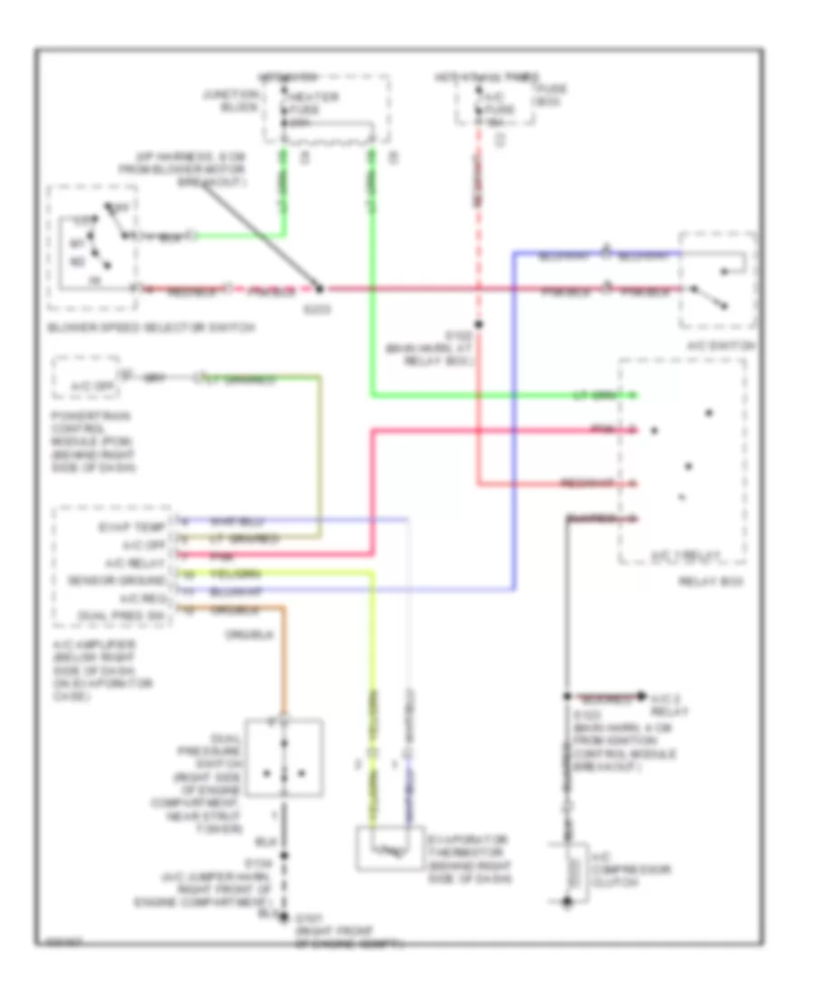
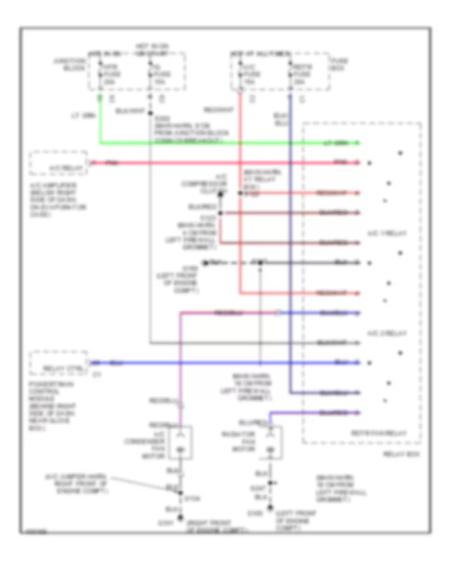
A/C Wiring Diagram for Chevrolet Metro LSi 1998
 https://portal-diagnostov.com/license.html
Automotive Electricians Portal FZCO
Automotive Electricians Portal FZCO
https://portal-diagnostov.com/license.html
https://portal-diagnostov.com/license.html
Automotive Electricians Portal FZCO
Automotive Electricians Portal FZCO
List of elements for A/C Wiring Diagram for Chevrolet Metro LSi 1998:
- (i/p harness, 8 cm from blower motor breakout)
- (i/p harness, behind right side of dash)
- (main harn, 18 cm from left firewall grommet)
- (main harn, behind left side of dash)
- 1995 vftc c
- A/c 1 relay
- A/c 2 relay
- A/c amplifier (below right side of dash, on evaporator case)
- A/c compressor clutch
- A/c condenser fan motor
- A/c fuse 15a
- A/c off
- A/c relay
- A/c req
- A/c switch
- Blower motor
- Blower motor resistor (in blower housing assembly)
- Blower speed selector switch
- Dual pres sw
- Dual pressure switch (right side of engine compartment, near strut tower)
- Engine controls system
- Evap temp
- Evaporator thermistor (behind right side of dash)
- Fuse box
- G100 (left front of engine compt)
- G101 (right front of engine compt)
- G200 (left kick panel)
- G206 (center of dash)
- Ground
- Heater fuse 20a
- Hot at all times
- Hot in on
- Hot in on or start
- Idle up
- Idle-up
- Ig-coil fuse 15a
- Ign
- Junction block
- Off
- Pnk
- Powertrain control module (pcm) (behind right side of dash, near glove box)
- Radiator fan motor
- Rdtr fan relay
- Rdtr fuse 30a
- Relay box
- Relay ctrl
- S122 (main harn, at relay box)
- S123 (main harn, 4 cm from ignition control module breakout)
- S134 (a/c jumper harn, right front of engine compartment)
- S202 (main harn, 8 cm from junction block connector c6 breakout)
- S210
- S232 (i/p harn, center of dash)
- S233
- S238 (i/p harness, 3 cm from blower motor breakout)
- S247
- S247 (main harn, 18 cm from left firewall grommet)
- S254
- Sensor ground
Compressor Wiring Diagram for Chevrolet Metro LSi 1998
List of elements for Compressor Wiring Diagram for Chevrolet Metro LSi 1998:
- (i/p harness, 8 cm from blower motor breakout)
- A/c 1 relay
- A/c 2 relay
- A/c amplifier (below right side of dash, on evaporator case)
- A/c compressor clutch
- A/c fuse 15a
- A/c off
- A/c relay
- A/c req
- A/c switch
- Blower speed selector switch
- Dual pres sw
- Dual pressure switch (right side of engine compartment, near strut tower)
- Evap temp
- Evaporator thermistor (behind right side of dash)
- Fuse box
- G101 (right front of engine compt)
- Heater fuse 20a
- Hot at all times
- Hot in on
- Junction block
- Off
- Pnk
- Powertrain control module (pcm) (behind right side of dash)
- Relay box
- S122 (main harn, at relay box)
- S134 (a/c jumper harn, right front of engine compartment)
- S233
- Sensor ground
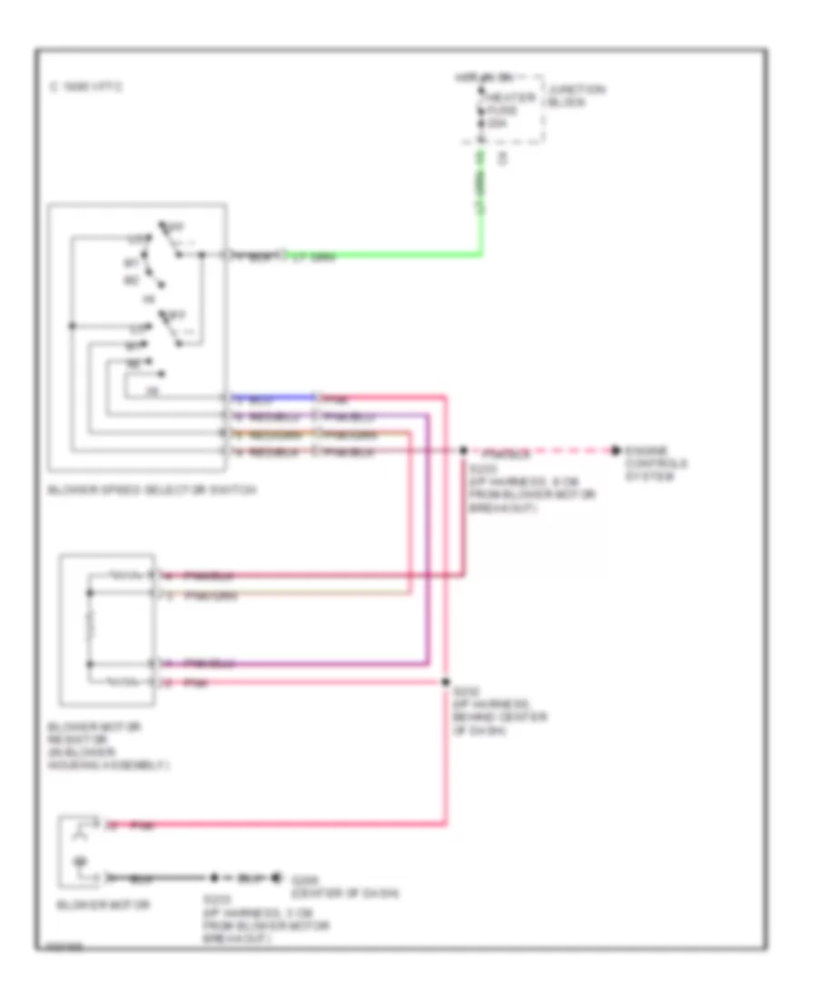
Heater Wiring Diagram for Chevrolet Metro LSi 1998
List of elements for Heater Wiring Diagram for Chevrolet Metro LSi 1998:
- 1995 vftc c
- Blower motor
- Blower motor resistor (in blower housing assembly)
- Blower speed selector switch
- Engine controls system
- G206 (center of dash)
- Heater fuse 20a
- Hot in on
- Junction block
- Off
- Pnk
- S232 (i/p harness, behind center of dash)
- S233 (i/p harness, 3 cm from blower motor breakout)
- S233 (i/p harness, 8 cm from blower motor breakout)
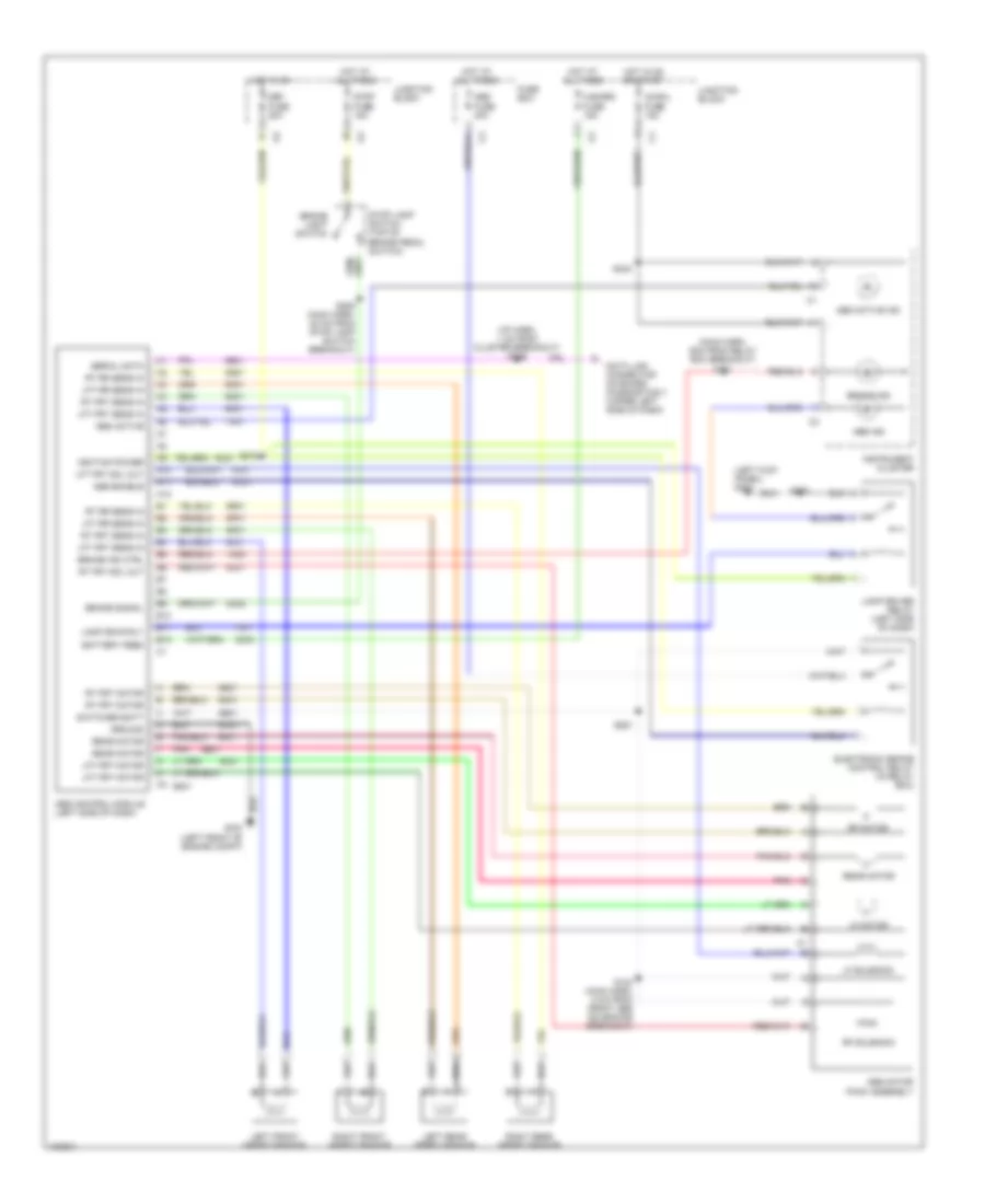
ANTI-LOCK BRAKES
Anti-lock Brake Wiring Diagrams for Chevrolet Metro LSi 1998
List of elements for Anti-lock Brake Wiring Diagrams for Chevrolet Metro LSi 1998:
- (i/p harn, 1 cm from cluster breakout) s249
- (left kick panel) g200
- (main harn, 9cm from relay box breakout) s121
- 1m03
- 2c03
- 2o02
- 6b01
- 6c01
- 6d01
- 6e01
- 6f01
- 6g01
- 6h01
- 6i01
- 6j01
- 6k01
- 6l01
- 6m01
- 6n01
- 6o01
- 6p01
- 6q01
- 6r01
- 6s01
- 6u01
- 6v01
- 6w01
- 7h01
- 7i01
- A10
- A11
- A12
- Abs active
- Abs active ind
- Abs control module (left side of dash)
- Abs enable
- Abs fuse 40a
- Abs ind
- Abs motor pack assembly
- B10
- B11
- B12
- Battery feed
- Brake ind
- Brake ind ctrl
- Brake light switch
- Brake signal
- Data link connector on board diagnostics ii (upper left side of dash)
- Def fuse 20a
- Electronic brake control relay (in relay box)
- Fuse box
- G100 (left front of engine compt)
- Ground
- Hazard fuse 15a
- Hot at all times
- Hot in on
- Hot in on or start
- Ig-coil fuse 15a
- Ignition power
- Instrument cluster
- Junction block
- Lamp driver relay (left side of dash)
- Lamp drvr rly
- Left front speed sensor
- Left rear speed sensor
- Lf motor
- Lf solenoid
- Lft frt motor
- Lft frt sens in
- Lft frt sol out
- Lft rr sens in
- Pnk
- Rear motor
- Rf motor
- Rf solenoid
- Right front speed sensor
- Right rear speed sensor
- Rt frt motor
- Rt frt sens in
- Rt frt sol out
- Rt rr sens in
- S124 (main harn, 5 cm from front abs solenoids breakout)
- S206 (main harn, 22 cm from stop lamp switch breakout)
- S208
- S215
- S242
- S251
- Serial data
- Stop fuse 15a
- Stop lamp switch (top of brake pedal switch)
- Switched batt
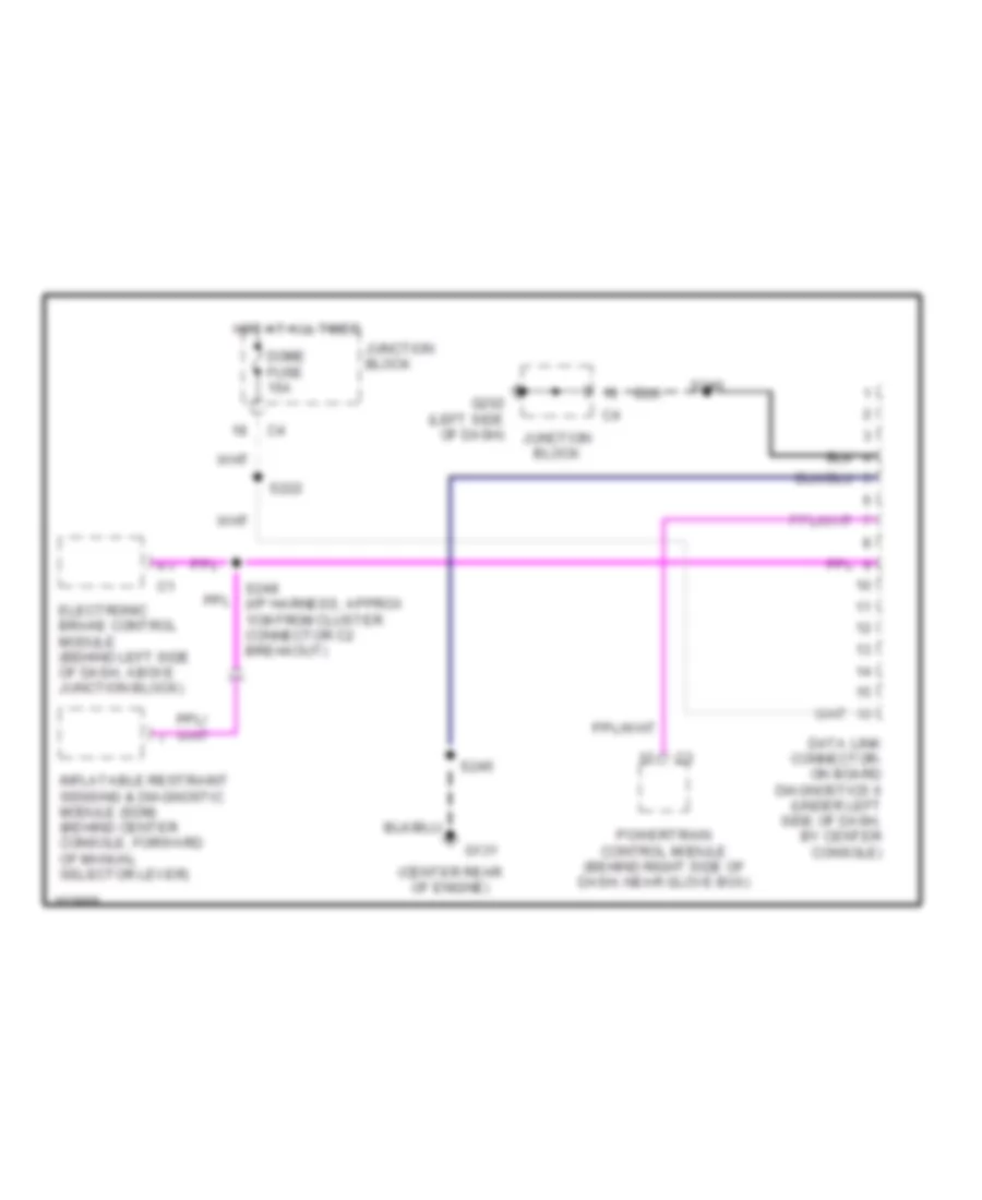
COMPUTER DATA LINES
Computer Data Lines for Chevrolet Metro LSi 1998
List of elements for Computer Data Lines for Chevrolet Metro LSi 1998:
- (center rear of engine)
- Data link connector- on board diagnostics ii (under left side of dash, by center console)
- Dome fuse 15a
- Electronic brake control module (behind left side of dash, above junction block)
- G131
- G202 (left side of dash)
- Hot at all times
- Inflatable restraint sensing & diagnostic module (sdm) (behind center console, forward of manual selector lever)
- Junction block
- Powertrain control module (behind right side of dash, near glove box)
- S222
- S240
- S245
- S249 (i/p harness, approx 1cm from cluster connector c2 breakout)
COOLING FAN
Cooling Fan Wiring Diagram for Chevrolet Metro LSi 1998
List of elements for Cooling Fan Wiring Diagram for Chevrolet Metro LSi 1998:
- (a/c jumper harn, right front of engine compt)
- (left front of engine compt)
- (main harn, 18 cm from left firewall grommet)
- (main harn, at relay box) s122
- (right front of engine compt)
- A/c 1 relay
- A/c 2 relay
- A/c amplifier (below right side of dash, on evaporator case)
- A/c compressor clutch
- A/c condenser fan motor
- A/c fuse 15a
- A/c relay
- Fuse box
- G100
- G100 (left front of engine compt)
- G101
- Hot at all times
- Hot in on junction block
- Hot in on or start
- Htr fuse 20a
- Ig fuse 15a
- Pnk
- Powertrain control module (behind right side of dash, near glove box)
- Radiator fan motor
- Rdtr fan relay
- Rdtr fuse 30a
- Relay box
- Relay ctrl
- S123 (main harn, 4 cm from left firewall grommet)
- S134
- S202 (main harn, 8 cm from junction block conn c6 breakout)
- S247
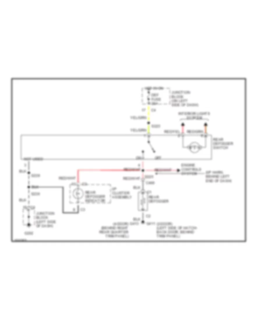
DEFOGGERS
Defogger Wiring Diagram for Chevrolet Metro LSi 1998
List of elements for Defogger Wiring Diagram for Chevrolet Metro LSi 1998:
- (2-door) (left side of hatch- back door, behind trim panel)
- (i/p harn, behind left end of dash)
- C406
- Def fuse 20a
- Engine controls system
- G202
- G411
- G413 (4-door) (behind right rear quarter trim panel)
- Hot in on
- I/p cluster assembly
- Interior lights system
- Junction block (left side of dash)
- Junction block (on left side of dash)
- Not used
- Off
- Rear defogger switch
- Rear defogger
- Rear defogger indicator
- S223
- S236
- S239
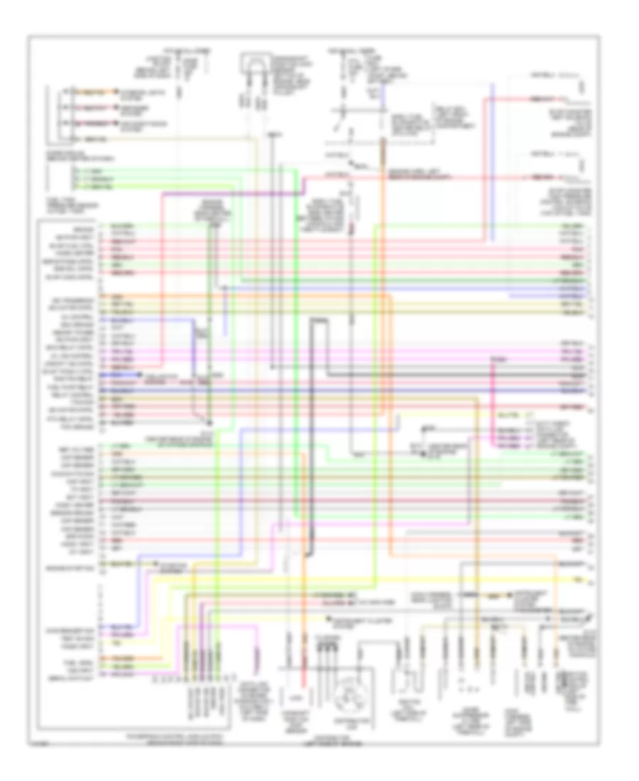
ENGINE PERFORMANCE
1.0L
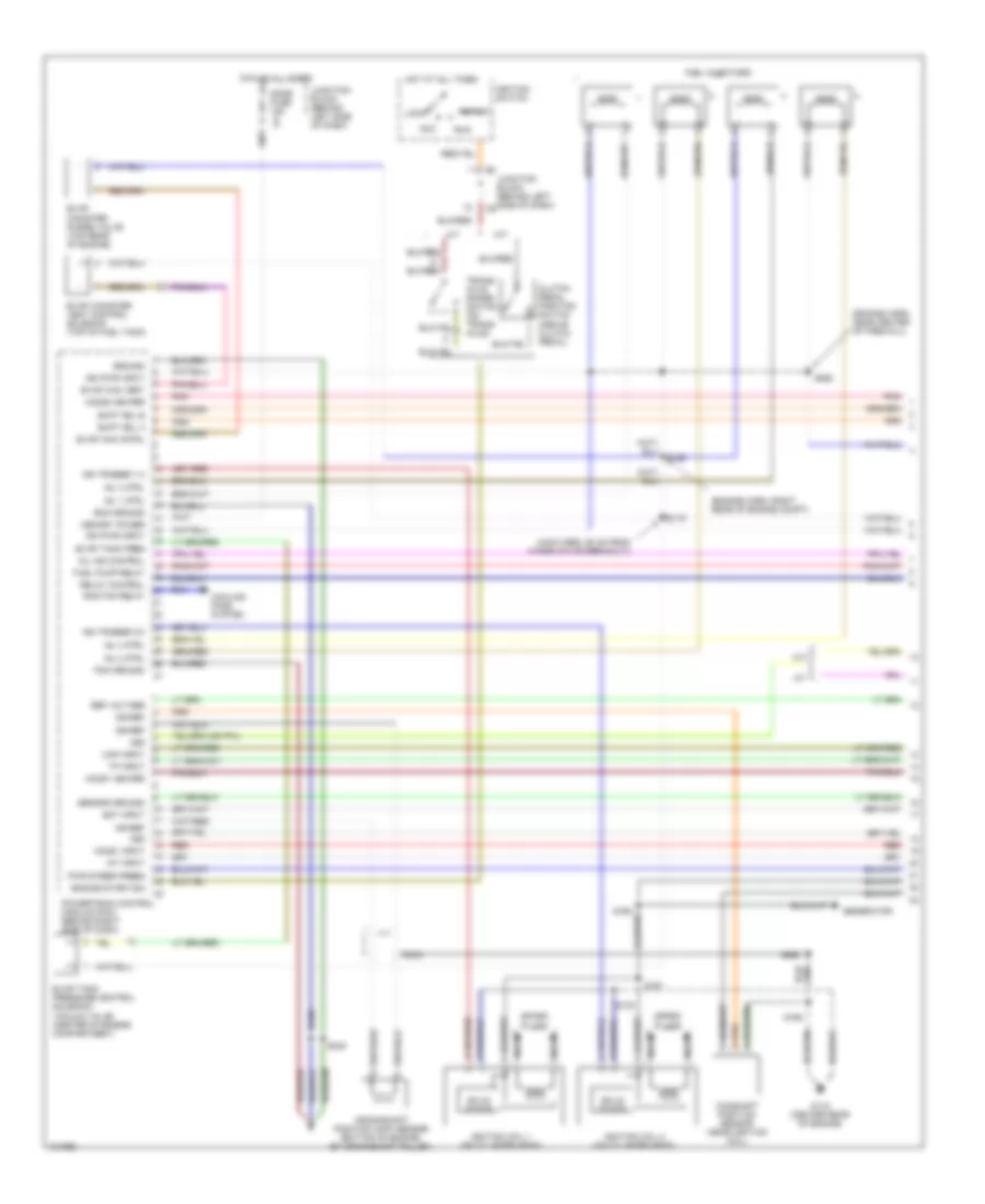
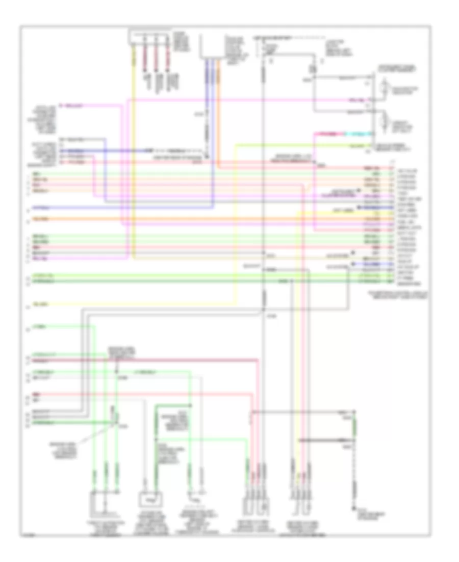
1.0L (VIN 6), Engine Performance Wiring Diagrams (1 of 2) for Chevrolet Metro LSi 1998
List of elements for 1.0L (VIN 6), Engine Performance Wiring Diagrams (1 of 2) for Chevrolet Metro LSi 1998:
- (center rear of engine) g115
- (engine harn, left rear of engine compt)
- (engine harness, near center of firewall) s262
- (main harness, left side of engine compt)
- (main harness, near junction block)
- A/c amplifier
- A/c cut-out
- Air conditioning system
- Camshaft position (cmp) sensor
- Ckp sensor
- Cmp sensor
- Cooling fan system
- Crankshaft position (ckp) sensor (bottom of engine, near crankshaft pulley)
- Data link connector on board diagnostics ii (dlc-obd ii) (left side of dash)
- Defogger system
- Diag request sig
- Diode module (behind center of dash)
- Distributor (left side of engine)
- Distributor cap
- Dome fuse 15a
- Duty check data link connector (left rear of engine compt)
- Early fuel evaporative (efe) heater (between intake manifold and red
- Early fuel evaporative heater relay (ptc htr)
- Ecm ground
- Ect input
- Efe on sig
- Egr bypass cntrl
- Egr sol cntrl
- Engine start sig
- Evap canister tank pressure control solenoid vacuum valve (top of fuel tank)
- Evap canister vent solenoid valve (rear of engine compt)
- Evap cann cntrl
- Evap cvsv ctrl
- Evap tpcsvv ctrl
- Fuel level
- Fuel pres
- Fuel pump relay
- Fuel tank pressure sensor (in fuel tank)
- Fuse box (left of eng compt, behind battery)
- G115 (center rear of engine, on intake manifold)
- Ground
- Ho2s1 heater
- Ho2s1 input
- Ho2s2 heater
- Ho2s2 input
- Hot at all times
- Iat input
- Idle switch sig
- Idle-up sig
- Ign coil control
- Ign pwr input
- Ign trig input ignition control module (left side of fire- wall)
- Ign trigger sig
- Ignition
- Ignition coil (left side of firewall)
- Inj control
- Instrument cluster system
- Instrument cluster system (tachometer)
- Interior lights system
- Isc motor cntrl
- Isca relay cntrl
- Junction block (behind left side of dash)
- Map input
- Memory power
- Mil ind control
- Nca
- Noise suppressor filter (left rear of firewall)
- Pcm ground
- Pnk
- Powertrain control module (pcm) (behind right side of dash)
- Ptc fuse 30a
- Ptc relay cntrl
- Rad fan relay
- Red
- Ref voltage
- Relay box (left front of engine compartment)
- Relay control
- S110
- S111
- S130
- S167
- S170
- S200
- S248
- S261
- Sensor ground
- Serial data out
- Starting system
- Tach sig
- Test sw sig
- Throttle body)
- To spark plugs
- Tp input
- Upshift ind cntrl
- Vss input
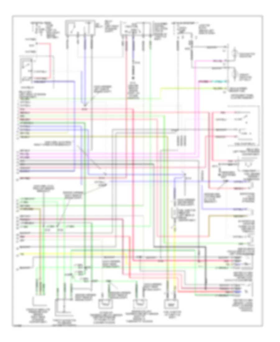
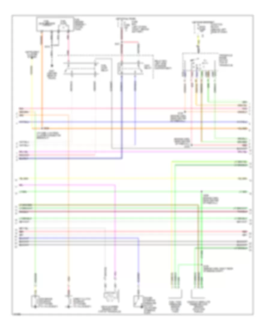
1.0L (VIN 6), Engine Performance Wiring Diagrams (2 of 2) for Chevrolet Metro LSi 1998
List of elements for 1.0L (VIN 6), Engine Performance Wiring Diagrams (2 of 2) for Chevrolet Metro LSi 1998:
- (center of engine, attached to air cleaner housing)
- (center rear of engine compt, on intake manifold)
- (engine harn, 4 cm from egr sv valve breakout)
- (engine harness, right rear of engine compt)
- (main harn, 23 cm from map sensor breakout)
- (main harn, 28 cm from front wiper motor breakout)
- (main harness, center rear of eng compt)
- (main harness, left side of engine compt)
- (main harness, right rear of eng compt)
- (near deck lid striker) g407
- (right of engine, in thermostat housing)
- Compartment)
- Egr bypass valve (top rear of engine)
- Egr solenoid vacuum (egr sv) valve (left side of engine)
- Engine coolant temperature (ect) sensor
- Evaporative canister purge valve (center of firewall)
- Fi fuse 15a c1
- Fuel injector (in throttle body)
- Fuel injector resistor (left rear of engine compartment)
- Fuel pump
- Fuel pump relay
- Fuel sender assembly (in fuel tank)
- Fuse box (left of eng compt, behind battery)
- G115
- Heated oxygen sensor 1 (ho2s) (front of engine in exhaust manifold)
- Heated oxygen sensor 2 (ho2s) (after 3-way catalytic converter)
- Hot at all times
- Hot in on or start
- Idle
- Idle speed control (isc) motor (top of engine, on throttle body)
- Ig-coil fuse 15a
- Instrument panel cluster assembly
- Intake air temperature (iat) sensor
- Isc relay
- Junction block (behind left side of dash)
- Main relay
- Malfunction indicator
- Manifold absolute pressure (map) sensor (right rear of engine compartment)
- Nca
- Open at idle
- Pnk
- Red
- Relay box (left front of engine
- Relay box (left front of engine compt)
- S118
- S119
- S120
- S126
- S129
- S130
- S131
- S148
- S151
- S152
- S153
- S156
- S168
- S169
- S257
- S313
- Switch
- Throttle position (tp) sensor (on throttle body)
- Upshift indicator (m/t only)
- Vehicle speed sensor (vss)
1.3L
1.3L (VIN 2), Engine Performance Wiring Diagrams (1 of 3) for Chevrolet Metro LSi 1998
List of elements for 1.3L (VIN 2), Engine Performance Wiring Diagrams (1 of 3) for Chevrolet Metro LSi 1998:
- (engine harn, near center of firewall)
- (engine harn, right rear of engine compt)
- (main harn, 50 cm from wimer motor breakout)
- A/t
- Acc
- Camshaft position sensor (near ignition coil)
- Clutch pedal position switch (above clutch pedal)
- Cooling fans system
- Crankshaft position (ckp) sensor (bottom of engine, by crankshaft pulley)
- Dome fuse 15a
- Ecm ground
- Ect input
- Engine start sig
- Evap can cntrl
- Evap can vent
- Evap canister purge valve (top rear of engine)
- Evap canister vent control solenoid (top of fuel tank)
- Evap tank pres
- Evap tank pressure control solenoid vacuum valve (center of engine compartment)
- Fuel injectors
- Fuel pump relay
- G115 (center rear of engine)
- Generator
- Ground
- Ho2s1 heater
- Ho2s1 input
- Ho2s2 heater
- Hot at all times
- Iat input
- Ign pwr input
- Ign ref
- Ign trigger 1-4
- Ign trigger 2-3
- Ignition coil 1 (on cylinder head)
- Ignition coil 2 (on cylinder head)
- Ignition switch
- Inj 1 ctrl
- Inj 2 ctrl
- Inj 3 ctrl
- Inj 4 ctrl
- Junction block (behind left side of dash)
- Junction block (behind left side of dash)
- Lock
- M/t
- Map input
- Memory power
- Mil ind control
- Nca
- Pcm ground
- Pnk
- Powertrain control module (pcm) (behind right side of dash)
- Pwr steer press
- Rad fan relay
- Red
- Ref voltage
- Relay control
- Run
- S119
- S130
- S159
- S160
- S161
- S165
- S248
- S262
- S263
- Sensor ground
- Shift sol a
- Shift sol b
- Solid state
- Spark plugs
- Start
- Tp input
- Trans- axle range switch (on trans- axle)
- Vss
1.3L (VIN 2), Engine Performance Wiring Diagrams (2 of 3) for Chevrolet Metro LSi 1998
List of elements for 1.3L (VIN 2), Engine Performance Wiring Diagrams (2 of 3) for Chevrolet Metro LSi 1998:
- (engine harn, near center of firewall)
- (i/p harn, 3 cm from cluster connector breakout)
- (left of eng compt, behind battery)
- 2nd brake solenoid (attached to valve body)
- Back fuse 15a
- Direct clutch solenoid (attached to valve body)
- Fi fuse 15a c1
- Fuel level sensor
- Fuel pump
- Fuel pump relay
- Fuel sender assembly (in fuel tank)
- Fuel tank pressure sensor (in fuel tank)
- Fuse box
- G407 (center rear of trunk)
- Hot at all times
- Hot in on or start
- Instrument cluster system
- Junction block (behind left side of dash)
- Main relay
- Manifold absolute pressure (map) sensor (on intake plenum)
- N d
- Pnk
- Power steering pressure switch (on power steering pump)
- Red
- Relay box (left side of engine compartment)
- S129 (engine harn, right rear of engine compt)
- S151
- S154
- S158
- S226
- S259
- S315
- Transaxle range switch (top of transaxle)
- Vehicle speed sensor (vss) (top of transaxle)
1.3L (VIN 2), Engine Performance Wiring Diagrams (3 of 3) for Chevrolet Metro LSi 1998
List of elements for 1.3L (VIN 2), Engine Performance Wiring Diagrams (3 of 3) for Chevrolet Metro LSi 1998:
- (center rear of engine) g115
- (engine harn, 4 cm from pcm breakout)
- (engine harn, 8 cm from map sensor breakout)
- (engine harn, near center of firewall)
- (not used)
- 2 pos sig
- A/c cut
- A/c idle up
- A/c system
- D pos sig
- Data link connector on board diagnostics ii (dlc-obdii) (left side of dash)
- Defogger system
- Diag req
- Diode module (behind center of dash)
- Duty check data link connector (left rear side of engine compt)
- Duty out
- Engine coolant temperature (ect) sensor (left side of engine, in thermostat housing)
- Ft pres
- Fuel lev
- G115 (center rear of engine)
- Heated oxygen sensor 1 (ho2s) (in exhaust manifold)
- Heated oxygen sensor 2 (ho2s) (after 3-way catalytic converter)
- Ho2s 2 sig
- Hot in on or start
- Iac valve
- Idle air control valve (top of engine, on throtle body)
- Idle up
- Ig-coil fuse 15a
- Ignition
- Instrument cluster system
- Instrument panel cluster assembly
- Intake air temperature (iat) sensor (center of eng, attached to air cleaner housing)
- Interior
- Junction block (behind left side of dash)
- L pos sig
- Lights system
- Malfunction indicator
- N pos sig
- Nca
- Not used
- P pos sig
- Pnk
- Powertrain control module (behind right side of dash)
- R pos sig
- Red
- S101
- S126
- S130
- S131 (engine harn, 9cm from generator breakout)
- S152
- S153
- S156
- S163 (engine harn, 2 cm from injector breakout)
- S164
- S167
- S242
- S248
- S261
- S263
- Sensor gnd
- Serial data
- Tach
- Test sw sig
- Throttle position (tp) sensor (on side of throttle body)
- Upshift indicator (m/t only)
- Vehicle speed sensor (vss) (m/t)
EXTERIOR LIGHTS
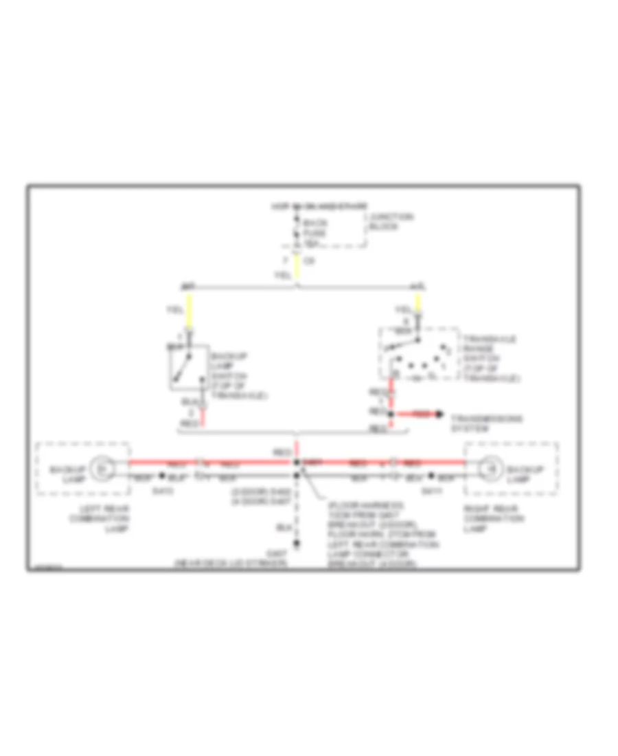
Backup Lamps Wiring Diagram for Chevrolet Metro LSi 1998
List of elements for Backup Lamps Wiring Diagram for Chevrolet Metro LSi 1998:
- (2-door) s402 (4 door) s407
- (floor harness, 13cm from g407 breakout (2-door), floor harn, 27cm from left rear combination lamp connector breakout (4 door)
- A/t
- Back fuse 15a
- Backup lamp
- Backup lamp switch (top of transaxle)
- G407 (near deck lid striker)
- Hot in on and start
- Junction block
- Left rear combination lamp
- M/t
- Red
- Red red
- Right rear combination lamp
- S401
- S411
- S413
- Transaxle range switch (top of transaxle)
- Transmissions system
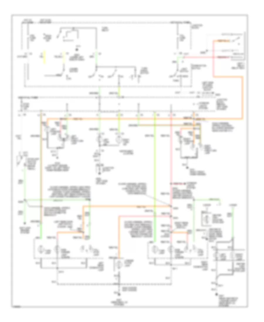
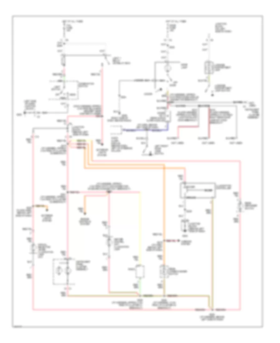
Exterior Lamps Wiring Diagram for Chevrolet Metro LSi 1998
List of elements for Exterior Lamps Wiring Diagram for Chevrolet Metro LSi 1998:
- (2 door)
- (a/t)
- (floor harness, approx 13cm (2-door) 34cm (4-dr) from left rear combination lamp conn breakout)
- (floor harness, approx 36cm from hatchback door harness breakout (2-door), floor harness, approx 39cm from left rear combination lamp connector breakout (4-door) s400
- (floor harness, approx 8cm from g407 breakout (2-door), floor harness, approx 10cm from luggage compt lamp switch connector breakout (4-door)
- (left rear comb lamp pigtail)
- (left side of dash) junction block
- (m/t)
- (main harness, approx 2cm from bulkhead grommet near master cyl)
- (main harness, approx 4cm from stoplamp switch connector breakout)
- (right rear comb lamp pigtail)
- 2 door
- 4 door
- Anti-lock brakes system
- Back fuse 15a
- Center high- mounted stoplamp
- Center of hatchback door, near rear wiper motor g410
- Combination switch
- G100 (lh front engine compt, on left front inner fender near
- G101 (right front inner fender)
- G202
- G202 (left side of dash)
- G202 (under left side of dash)
- G407 (near deck lid striker)
- G407 (rear center of luggage compt, near deck lid striker)
- Haz fuse 15a
- Hazard switch
- Head
- Hot at all times
- Hot in on and start
- Instrument cluster
- Interior lights system
- Junction block
- Junction block (behind left side of dash)
- Left front park/turn lamp
- Left parking lamp
- Left rear combination lamp
- Left stop lamp
- Left turn ind
- License plate lamp
- Light 1 relay (relay box)
- Light switch
- Off
- Park
- Right front park/turn lamp
- Right parking lamp
- Right rear combination lamp
- Right stop lamp
- Right turn ind
- S100
- S102
- S113
- S117
- S204
- S206
- S240
- S256
- S302 (floor harness, approx 5cm from center console branch breakout)
- S402 (2-door) s407 (4-door)
- S404
- S405
- S410 (2 door)
- S411
- S412
- S413
- Side marker lamp (2 door)
- Stop fuse 15a
- Stoplamp switch (top of brake pedal)
- Tail fuse 15a
- Tail/ stop lamp
- Turn lamp
- Turn relay
- Turn signal switch
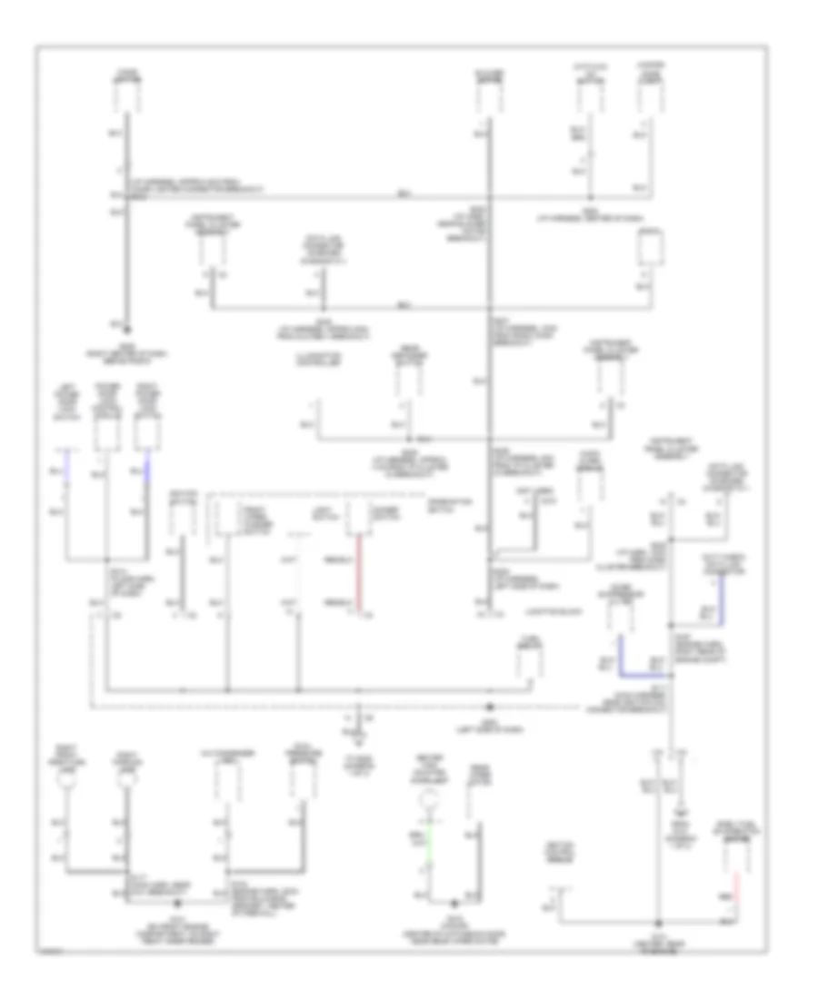
GROUND DISTRIBUTION
Ground Distribution Wiring Diagram (1 of 3) for Chevrolet Metro LSi 1998
List of elements for Ground Distribution Wiring Diagram (1 of 3) for Chevrolet Metro LSi 1998:
- c1
- (main harness, approx 8cm from bulkhead grommet, near master cylinder)
- (with abs) lamp driver relay
- A/c 2 relay (condenser
- A/c amplifier
- Battery
- Braid
- Brake fluid level switch
- Camshaft position sensor
- Crankshaft position sensor shield
- D c2
- Daytime running lamps control module
- Distributor shield
- Electronic brake control module
- Engine fan motor
- Fan)
- From j/b (diagram 2 of 3)
- Front washer pump
- G100 (lh front engine compartment, on lh front inner fender near battery)
- G108 (lh front engine compartment, front of battery)
- G130 (mounted on top lh side of transaxle)
- G131 (center rear of engine,on intake manifold)
- G200 (behind left kick panel)
- Heated oxygen sensor #1 shield
- Heated oxygen sensor 2 shield
- Horn
- Idle air control valve
- Idle speed control motor
- Ignition ccoil no 1
- Ignition ccoil no 2
- Left front turn lamp
- Left parking lamp
- Light 2 relay
- Powertrain control module
- Rear washer pump
- Relay box
- S113 (main harness, approx 6cm from left front turn lamp connector breakout)
- S115 (main harness, near rear washer pump)
- S130 engine harness, near generator connector breakout)
- S165 (engine harn, near starter breakout)
- S207 (main harness, approx 15cm from g200)
- S208 (main harness, 2cm from junction block connector c8 breakout)
- S209
- S210 (main harness, left side of dash)
- S213 (main harn, near master cylinder)
- S247 (main harness, left rear of engine compt))
- S248 (engine harn, at pcm branch breakout)
- S263 (engine harn, at pcm branch breakout)
- To s111 (diagram 2 of 3)
- Vin 2
- W/ abs
Ground Distribution Wiring Diagram (2 of 3) for Chevrolet Metro LSi 1998
List of elements for Ground Distribution Wiring Diagram (2 of 3) for Chevrolet Metro LSi 1998:
- (4-door)
- (i/p harness, approx 5cm from cigar lighter connector breakout) s243
- (not used)
- (with a/c) a/c switch
- A/c condenser fan
- Audio alarm module
- Blower motor
- C210
- Center high mounted stop lamp
- Cigar lighter
- Combination switch
- Data link connector on-board diagnostic ii
- Data link connector- on-board diagnostic ii
- Dimmer switch
- Dome lamp
- Dual pressure switch
- Duty check data link connector
- Early fuel evaporation heater
- From g131 (diagram 1 of 3)
- Front wiper/ washer switch
- G101 (rh front engine compartment, on right front inner fender)
- G131 (center rear of engine)
- G202 (left side of dash)
- G206 (right center of dash, behind radio)
- G410 (2-door) (center of hatchback door, near rear wiper motor)
- Ignition control module
- Ignition switch
- Illumination controller
- Instrument panel cluster assembly
- Junction block
- Left power door lock switch
- Light switch
- Noise suppressor filter
- Power door lock control module
- Radio
- Rear defogger switch
- Rear wiper motor
- Red
- Right front park/turn lamp
- Right parking lamp
- Right power door lock switch
- S111 (main harness, near ignition coil connector breakout)
- S117 (main harn, near g101 breakout)
- S134 (engine harn, 22cm from bulkhead grommet, center of firewall)
- S167 (engine harn, right rear of engine compt)
- S235 (i/p harness, left side of dash)
- S236 (i/p harness, 8cm from i/p cluster c3 breakout)
- S237 (i/p harness, 10cm from radio conn breakout)
- S238 (i/p harn, near blower motor breakout)
- S239 (i/p harness, approx 11cm from i/p cluster c3 breakout)
- S240 (i/p harness, approx 6cm from dlc-obd ii breakout)
- S245 (i/p harn, 12cm from dash cluster breakout)
- S254 (i/p harness, center of dash)
- S314 (floor harn, left side of dash)
- To s209 (diagram 1 of 3)
- Turn relay
- Vin
Ground Distribution Wiring Diagram (3 of 3) for Chevrolet Metro LSi 1998
List of elements for Ground Distribution Wiring Diagram (3 of 3) for Chevrolet Metro LSi 1998:
- (floor harness, approx 20cm from center console branch breakout) s301
- (floor harness, approx 20cm from left rear combination lamp conn breakout) s407
- (floor harness, approx 5cm from left rear combination lamp connector breakout) s402
- 2 door
- 4 door
- Below right rear seat)
- Center high mounted stop lamp
- Forward discriminating sensor
- Fuel assembly unit
- Fuel sender assembly
- G203 (behind right kick panel)
- G407 (rear center of lug- gage compartment, near deck lid striker)
- G411 (2-door) (left side of hatch- back door, behind trim panel)
- G413 (4-door) (behind right rear quarter trim panel)
- Left rear combination lamp
- License plate lamp
- Rear defogger
- Red
- Right rear combination lamp
- S311 (floor harness, approx 10cm from breakout to luggage compartment harness)
- S315 (fuel tank jumper harness,
- S403 (floor harness, approx 5cm from g407 breakout)
- S406 (floor harness, approx 10cm from left rear combination lamp connector breakout)
- S408 (floor harness)
- S411 (right rear combination lamp pigtail, approx 6cm from grommet at right rear of trunk)
- S413 (left rear combination lamp pigtail, approx 6cm from grommet at left rear of trunk)
- Seat belt switch
- Sensing and diagnostic module
- Shift lock solenoid
- Under right rear seat)
HEADLIGHTS
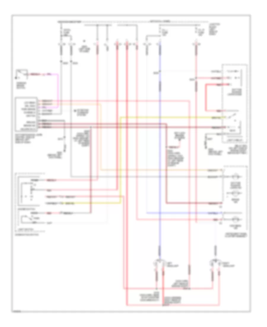
Headlight Wiring Diagram for Chevrolet Metro LSi 1998
List of elements for Headlight Wiring Diagram for Chevrolet Metro LSi 1998:
- (main harn, left rear of engine compt) s104
- (main harness, right rear of engine compt) s107
- Anti-lock brakes systems
- Brake ind
- C5 red
- Charge in
- Combination switch
- Daytime running lamps control module (behind left side of dash)
- Daytime running lamps diode
- Daytime running lamps ind
- Dimmer switch
- Drl indic
- G200 (behind left kick panel)
- G202 (left side of dash)
- Ground
- H/l, l fuse 15a
- H/l, r fuse 15a
- Hdlmps on in
- Head
- High beam ind
- Hot at all times
- Hot in on and start
- Ig-coil fuse 15a
- Ignition
- Instrument panel cluster assembly
- Junction block (left side of dash)
- Left headlamp
- Light 2 relay
- Light switch
- Low beam
- Off
- Park
- Park brake
- Parking brake switch
- Pass
- Red
- Relay box (on left side of engine compt, behind battery)
- Right headlamp
- S105 (main harn, near evap canister conn breakout)
- S202
- S205 (main harn, approx 1cm from grommet at left rear of engine compt)
- S207
- S210
- S223 (main harn, approx 10cm from grommet at left rear of engine compt)
- S242
- S246
- Starting/ charging system
HORN
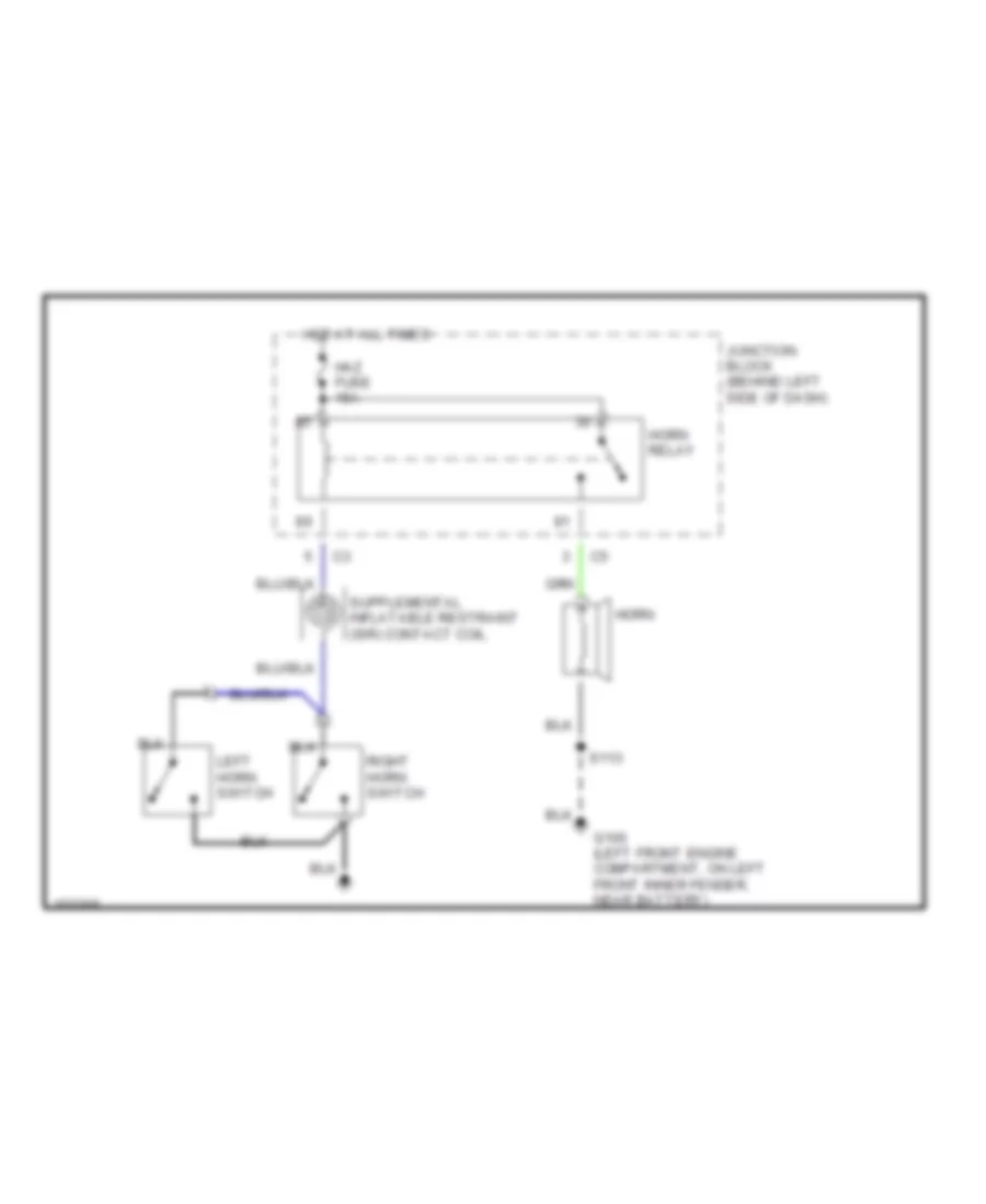
Horn Wiring Diagram for Chevrolet Metro LSi 1998
List of elements for Horn Wiring Diagram for Chevrolet Metro LSi 1998:
- G100 (left front engine compartment, on left front inner fender, near battery)
- Haz fuse 15a
- Horn
- Horn relay
- Hot at all times
- Junction block (behind left side of dash)
- Left horn switch
- Right horn switch
- S113
INSTRUMENT CLUSTER
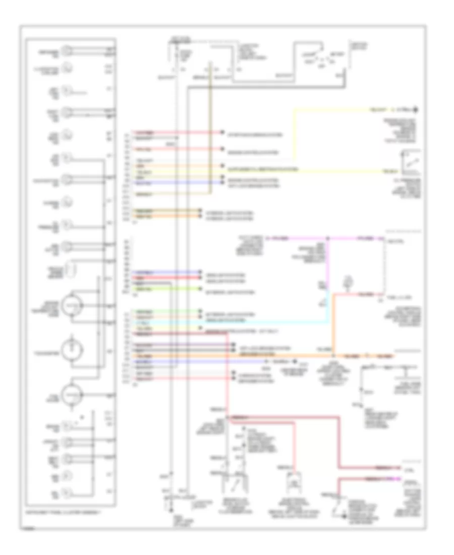
Instrument Cluster Wiring Diagram for Chevrolet Metro LSi 1998
List of elements for Instrument Cluster Wiring Diagram for Chevrolet Metro LSi 1998:
- (center rear of engine)
- (m/t only)
- 1.3l vin 9 only
- A10
- A11
- A12
- A13
- A14
- A15
- A16
- A16 c1
- Abs active ind
- Abs ind
- Accy
- Air bag ind
- Anti-lock brakes system
- B10
- B10 c2
- Brake fluid level switch (in brake fluid reservoir)
- Brake ind
- C1 b5
- C10
- C11
- C12
- C13
- C13 c3
- Charge ind
- Ctrl
- Data link connector (behind right side of dash)
- Daytime running lamps control module (behind left side of dash)
- Defogger ind
- Defogger system
- Drl ind
- Duty check
- Electronic brake control module (behind left side of dash, above junction block)
- Engine controls system
- Engine coolant temperature gage
- Engine coolant temperature sensor (on rear of engine, in t'stat housing)
- Exterior lights system
- Fuel gage sending unit (in fuel tank)
- Fuel gauge
- Fuel lvl sig
- G100 (lh front engine compt, on lh front inner fender, near battery)
- G131
- G202 (left side of dash)
- G407 (rear center of luggage compt, near deck lid striker)
- Headlights system
- High beam ind
- Hot in on and start
- Ig-coil fuse 15a
- Ignition switch
- Illumination (2 bulbs)
- Ind ctrl
- Instrument panel cluster assembly
- Interior lights system
- Junction block
- Junction block (on left side of dash)
- Left turn ind
- Lock
- Malfunction ind
- Off
- Oil pressure ind
- Oil pressure switch (left side of engine, above oil filter)
- Parking brake switch (under floor console, on parking brake lever base)
- Powertrain control module (behind right side of dash, near glove box)
- Red
- Right turn ind
- S213
- S223 (main harn, left rear of engine compt)
- S226 (dash harn, approx 2cm from cluster connector c3 breakout)
- S240
- S242
- S245
- S261 (engine harn, 4cm from pcm connectors breakout)
- S315
- Seat belt ind
- Signal
- Start
- Starting/charging system
- Tachometer
- Upshift ind (m/t)
- Vehicle speed sensor
- Warning system
INTERIOR LIGHTS
Interior Light Wiring Diagram for Chevrolet Metro LSi 1998
List of elements for Interior Light Wiring Diagram for Chevrolet Metro LSi 1998:
- (4-door)
- (i/p harn, behind left side of dash) s217
- (i/p harness, approx 4 cm from data link connector- on board diagnostics ii breakout) s252
- (i/p harness, approx 6 cm from diode module connector breakout)
- (left side of dash) junction block
- (main harness, approx 2 cm from bulkhead grommet near master cylinder) s204
- (not used)
- (not used)
- (right side of dash, behind radio)
- 2-door
- Audio alarm module (behind dash, left of steering column)
- Bulbs
- C10
- Combination switch
- Diode no 1 (near audio alarm module)
- Dome fuse 15a
- Dome lamp
- Door
- Engine controls system
- Exterior lights system
- G202
- G206
- Ground
- Head
- Heater control unit illumination lamp
- Hot at all times
- Illumination controller
- Instrument panel cluster assembly
- Junction block (behind left side of dash)
- Junction block (on left side of dash)
- Left front door jamb switch
- Light 1 relay (on relay box)
- Light switch
- Luggage compartment lamp
- Luggage compartment lamp switch
- Manual selector lever illumination lamp (a/t)
- Off
- Park
- Power
- Radio
- Rear defogger switch
- Rear wiper/washer switch
- S218 (i/p harness, approx 3 cm from i/p cluster c3 breakout)
- S219 (i/p harn, behind left side of dash)
- S221 (i/p harness, approx 7 cm from i/p cluster c2 breakout)
- S222
- S228 (i/p harness, behind left side of dash)
- S229 (i/p harness, approx 4 cm from i/p cluster c1 breakout)
- S230 (i/p harness, 13 cm from i/p cluster c3 breakout)
- S239
- S254
- S302 (floor harn, behind left side of dash)
- S310 (floor harness, approx 6 cm from junction block conn breakout)
- S419 (floor harness, approx 21 cm from right rear door jamb sw conn breakout)
- Tail fuse 15a
- Warning system
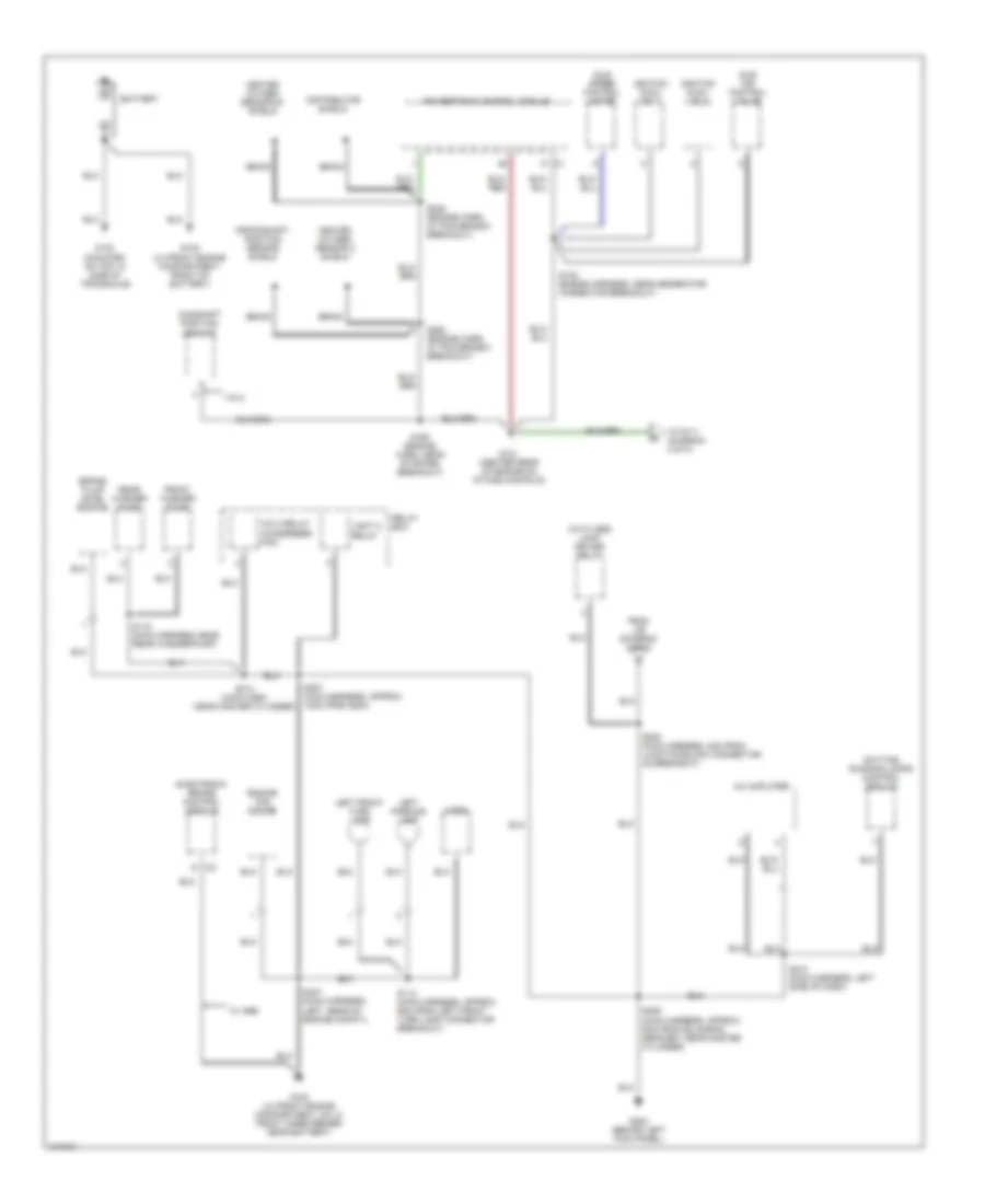
POWER DISTRIBUTION
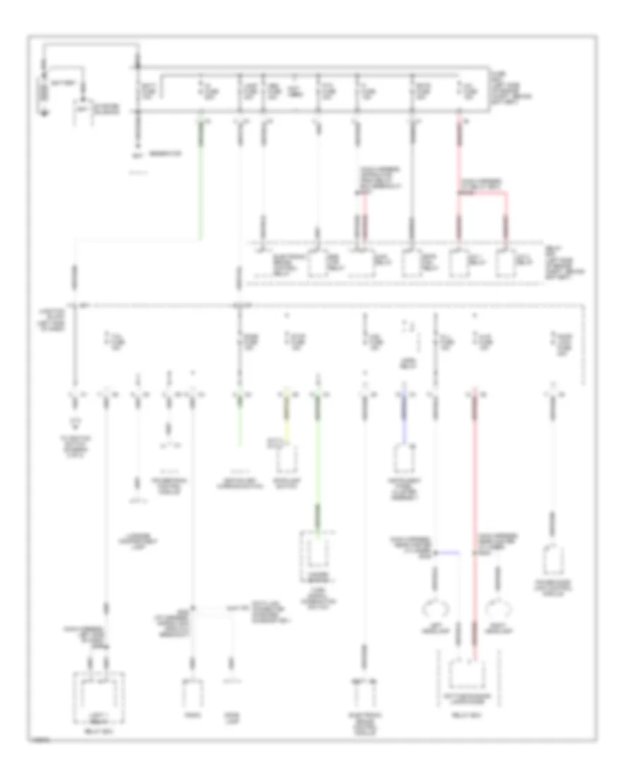
Power Distribution Wiring Diagram (1 of 2) for Chevrolet Metro LSi 1998
List of elements for Power Distribution Wiring Diagram (1 of 2) for Chevrolet Metro LSi 1998:
- (m/t) (a/t)
- (main harness, approx 5cm from relay box breakout) s151
- (main harness, at relay box) s122
- (main harness, left side of dash) s256
- (main harness, near master cylinder) s244
- (main harness, near master cylinder) s246
- (not used)
- A/c 1 relay
- A/c 2 relay
- A/c fuse 15a
- Abs fuse 40a
- B12
- Bat
- Batt fuse 70a
- Battery
- Data link connector- on-board diagonstics ii
- Daytime running lamps diode
- Dome fuse 15a
- Dome lamp
- Door lock fuse 20a
- Efe htr relay
- Electronic brake control module
- Electronic brake control relay
- Fi fuse 15a
- Fuse box (left side of engine compt, behind battery)
- Generator
- Haz fuse 15a
- Hazard switch
- Hl-l fuse 15a
- Hl-r fuse 15a
- Horn relay
- Ig fuse 60a
- Ignition key warning switch
- Instrument panel cluster assembly
- Junction block (left side of dash)
- Lamp fuse 40a
- Left headlamp
- Light 1 relay
- Luggage compartment lamp
- Main relay
- Power door lock control module
- Powertrain control module
- Ptc fuse 30a
- Radio
- Rdtr fan relay
- Rdtr fuse 30a
- Relay box
- Relay box (left side of engine compt, behind battery)
- Right headlamp
- S222 (i/p harness, approx 6cm from dlc breakout)
- Starter solenoid
- Stop fuse 15a
- Stoplamp switch
- Tail fuse 15a
- To ignition switch (diagram 2 of 2)
- Turn signal/ combination switch
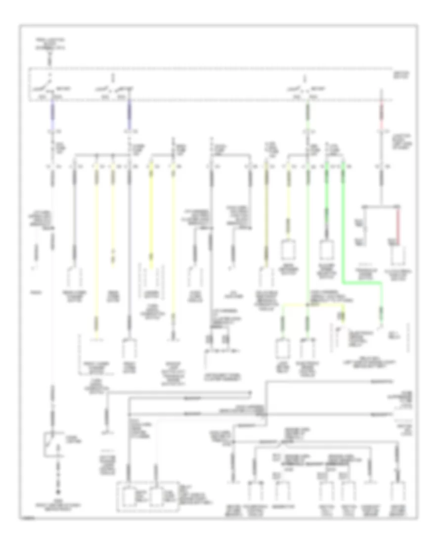
Power Distribution Wiring Diagram (2 of 2) for Chevrolet Metro LSi 1998
List of elements for Power Distribution Wiring Diagram (2 of 2) for Chevrolet Metro LSi 1998:
- (engine harn, center of firewall) s126
- (engine harn, near generator breakout)
- (i/p harn, approx 6cm from dlc breakout) s224
- (i/p harness, 5cm from cluster conn breakout) s241
- (i/p harness, at cluster conn breakout) s242
- (main harn, 8cm from junction block breakout) s202
- (main harn, center of firewall) s152
- (main harness, approx 10cm from breakout to i/p harn) s215
- (main harness, near master cylinder) s100
- A/c 1 relay
- A/c amplifier
- A/t
- Acc
- Acc fuse 15a
- Air bag fuse 15a
- Audio alarm module
- Back fuse 15a
- Backup lamp switch (m/t) transaxle range switch (a/t)
- Blower speed selector switch
- Camshaft position sensor
- Cigar lighter
- Clutch pedal position switch
- Daytime running lamps control module
- Def fuse 20a
- Electronic brake control module
- Electronic brake control relay
- From junction block (diagram 1 of 2)
- Front wiper motor
- Front wiper/ washer switch
- Fuel pump relay
- G206 (right center of dash) behind radio)
- Generator
- Hazard switch
- Heated oxygen sensor 1
- Heated oxygen sensor 2
- Htr fuse 20a
- Ig-coil fuse 15a
- Ignition coil (vin 6)
- Ignition coil 1 (vin 2)
- Ignition coil 2 (vin 2)
- Ignition switch
- Inflatable restraint sensing & diagnostics module
- Instrument panel cluster assembly
- Junction block (left side of dash)
- Lamp driver relay
- Lock
- M/t
- Noise suppressor filter (vin 6)
- Powertrain control module
- Radio
- Rdtr fan relay
- Rear defogger switch
- Rear wiper motor
- Rear wiper/ washer switch
- Relay box (left side of engine compt, behind battery)
- Run
- S101 (main harn, near master cylinder)
- S160
- S161
- Start
- Transaxle range switch
- Turn/ signal combination switch
- Wiper fuse 15a
POWER DOOR LOCKS
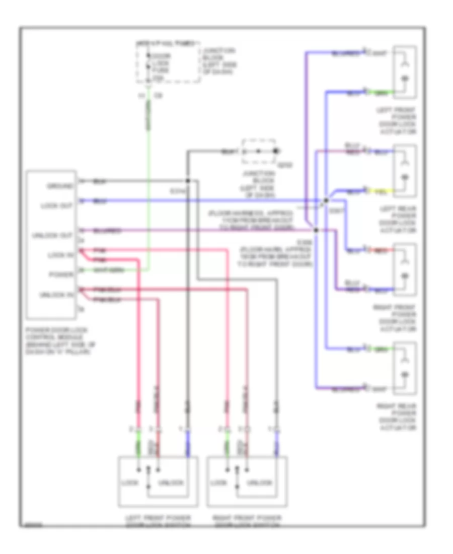
Power Door Lock Wiring Diagram for Chevrolet Metro LSi 1998
List of elements for Power Door Lock Wiring Diagram for Chevrolet Metro LSi 1998:
- (floor harness, approx 11cm from breakout to right front door)
- Door lock fuse 20a
- G202
- Ground
- Hot at all times
- Junction block (left side of dash)
- Left front power door lock actuator
- Left front power door lock switch
- Left rear power door lock actuator
- Lock
- Lock in
- Lock out
- Pnk
- Power
- Power door lock control module (behind left side of dash on "a" pillar)
- Red
- Right front power door lock actuator
- Right front power door lock switch
- Right rear power door lock actuator
- S307
- S308 (floor harn, approx 19cm from breakout to right front door)
- S314
- Unlock
- Unlock in
- Unlock out
RADIO
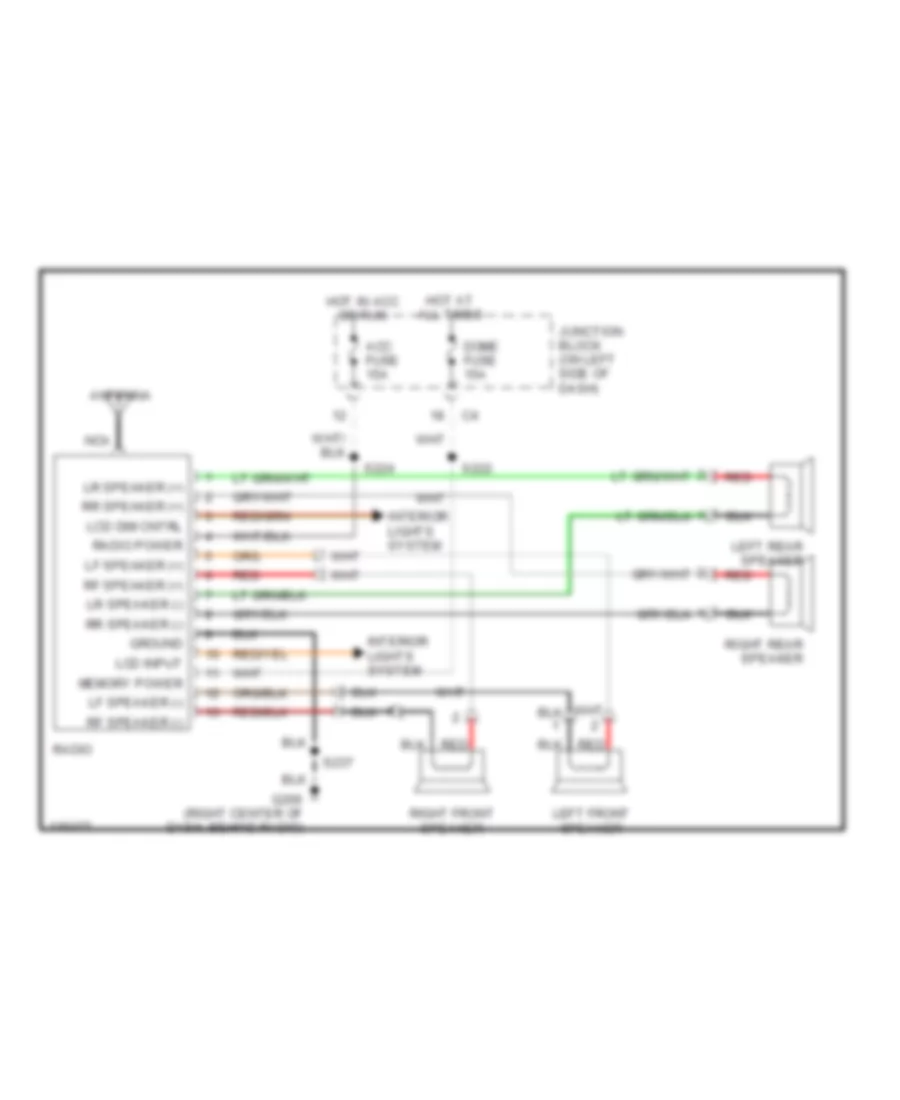
Radio Wiring Diagrams for Chevrolet Metro LSi 1998
List of elements for Radio Wiring Diagrams for Chevrolet Metro LSi 1998:
- Acc fuse 15a
- Antenna
- Dome fuse 15a
- G206 (right center of dash, behind radio)
- Ground
- Hot at all times
- Hot in acc or run
- Interior lights system
- Junction block (on left side of dash)
- Lcd dim cntrl
- Lcd input
- Left front speaker
- Left rear speaker
- Lf speaker (+)
- Lf speaker (-)
- Lr speaker (+)
- Lr speaker (-)
- Memory power
- Nca
- Radio
- Radio power
- Red
- Rf speaker (+)
- Rf speaker (-)
- Right front speaker
- Right rear speaker
- Rr speaker (+)
- Rr speaker (-)
- S222
- S224
- S237
SHIFT INTERLOCKS
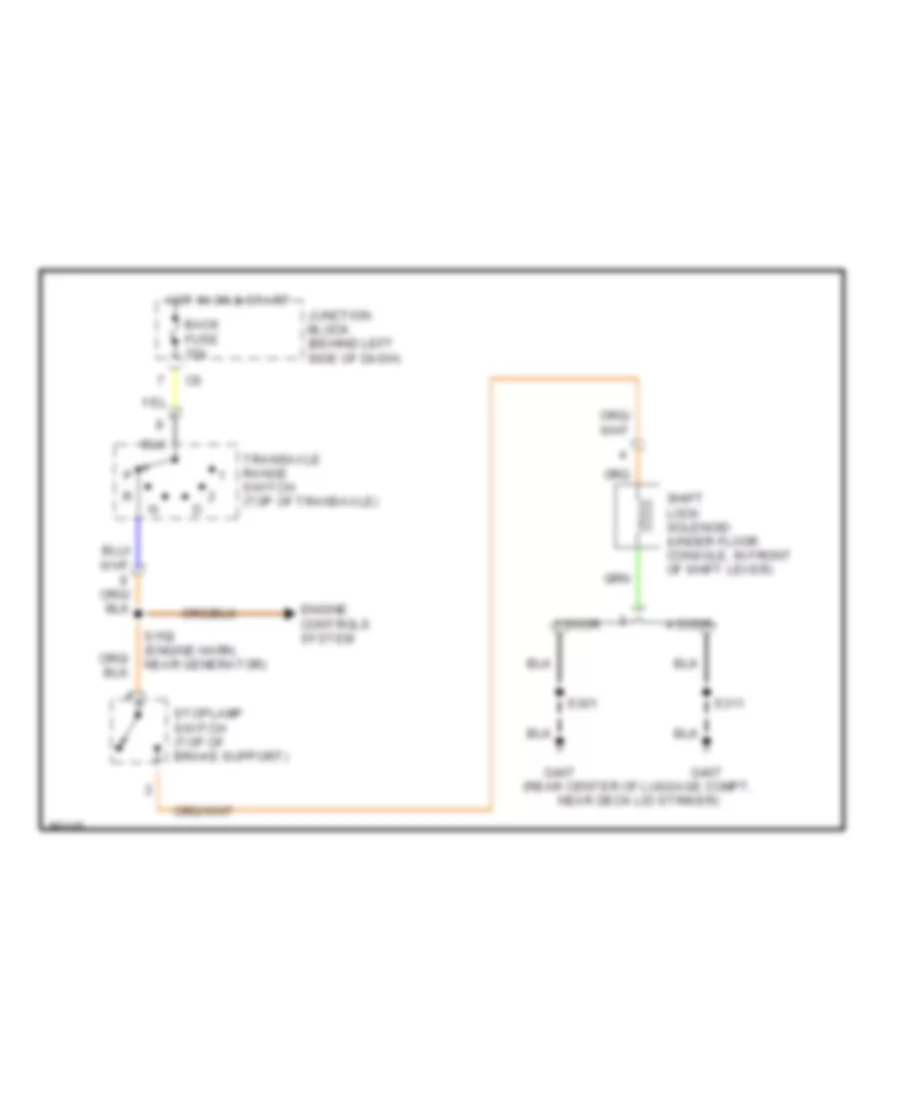
Shift Interlock Wiring Diagram for Chevrolet Metro LSi 1998
List of elements for Shift Interlock Wiring Diagram for Chevrolet Metro LSi 1998:
- (rear center of luggage compt, near deck lid striker)
- 2 door
- 4 door
- Back fuse 15a
- Engine controls system
- G407
- Hot in on & start
- Junction block (behind left side of dash)
- S158 (engine harn, near generator)
- S301
- S311
- Shift lock solenoid (under floor console, in front of shift lever)
- Stoplamp switch (top of brake support)
- Transaxle range switch (top of transaxle)
STARTING/CHARGING
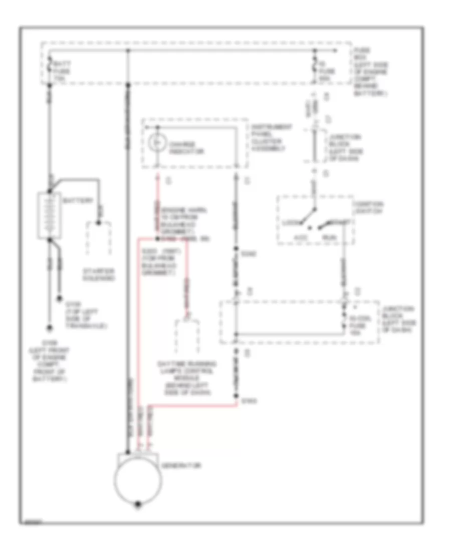
Charging Wiring Diagram for Chevrolet Metro LSi 1998
List of elements for Charging Wiring Diagram for Chevrolet Metro LSi 1998:
- (1997)
- (1998, 99)
- (engine harn, 10 cm from bulkhead grommet) s162
- Acc
- Batt fuse 70a
- Battery
- Charge indicator
- Daytime running lamps control module (behind left side of dash)
- Fuse box (left side of engine compt, behind battery)
- G108 (left front of engine compt, front of battery)
- G130 (top left side of transaxle)
- Generator
- Ig fuse 60a
- Ig-coil fuse 15a
- Ignition switch
- Instrument panel cluster assembly
- Junction block (left side of dash)
- Lock
- Run
- S160
- S203 (1cm from bulkhead grommet)
- S242
- Start
- Starter solenoid
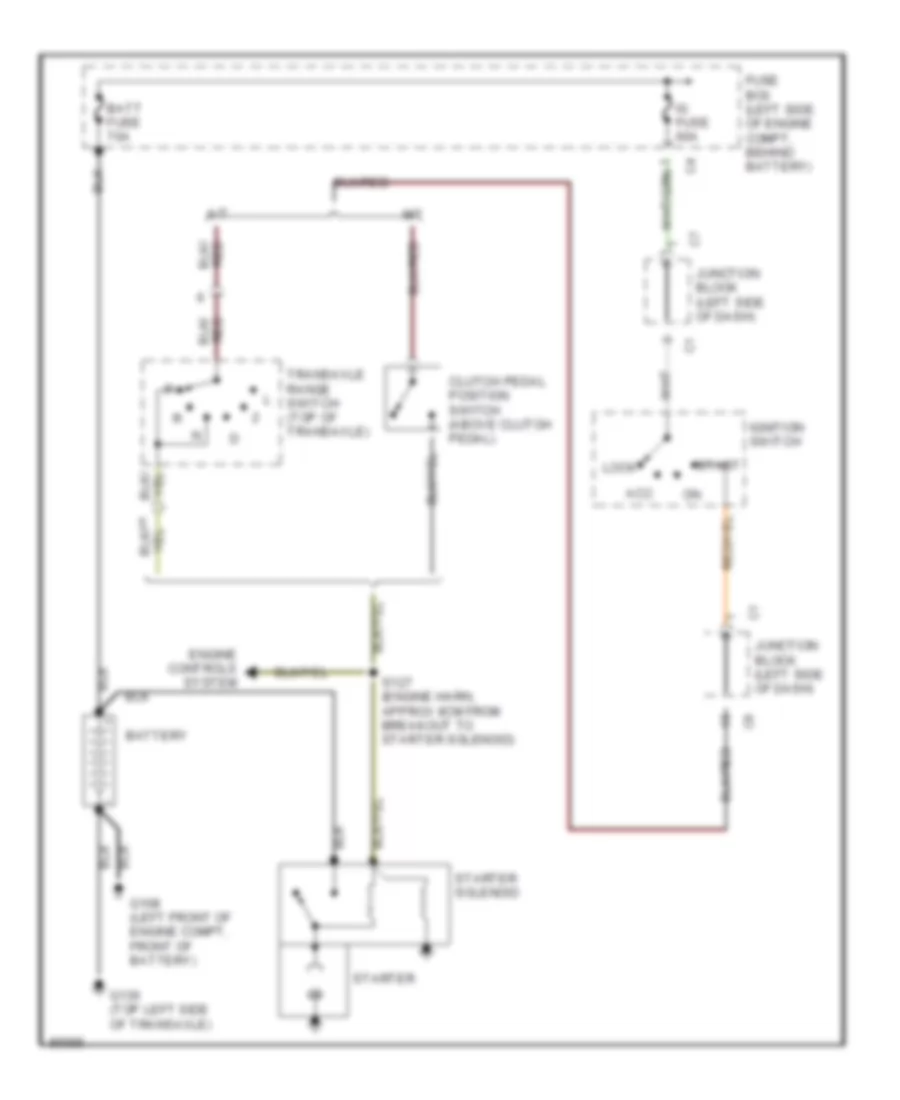
Starting Wiring Diagram for Chevrolet Metro LSi 1998
List of elements for Starting Wiring Diagram for Chevrolet Metro LSi 1998:
- A/t
- Acc
- Batt fuse 70a
- Battery
- Clutch pedal position switch (above clutch pedal)
- Engine controls system
- Fuse box (left side of engine compt, behind battery)
- G108 (left front of engine compt, front of battery)
- G130 (top left side of transaxle)
- Ig fuse 60a
- Ignition switch
- Junction block (left side of dash)
- Lock
- M/t
- S127 (engine harn, approx 8cm from breakout to starter solenoid)
- Start
- Starter
- Starter solenoid
- Transaxle range switch (top of transaxle)
SUPPLEMENTAL RESTRAINTS
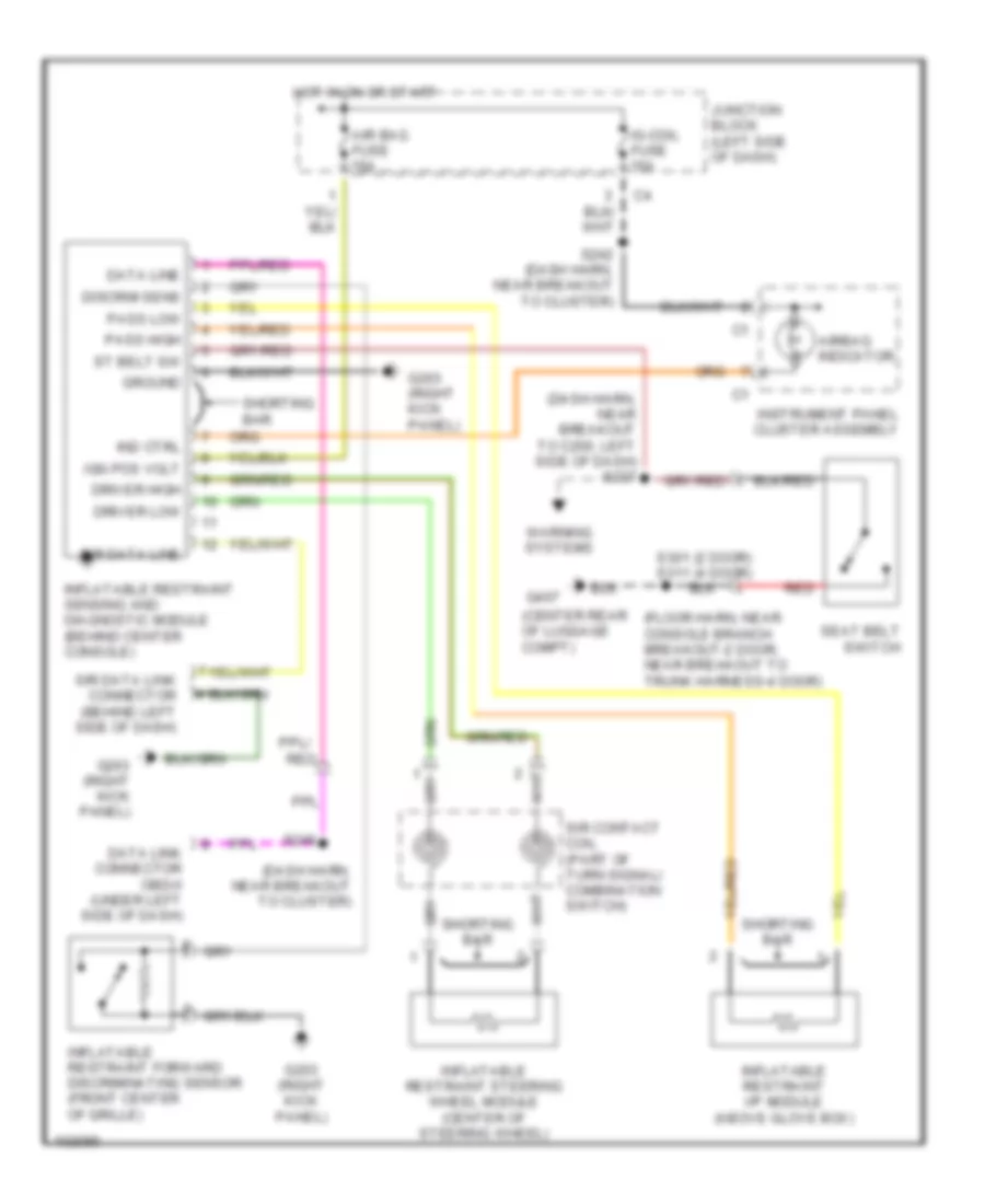
Supplemental Restraint Wiring Diagram for Chevrolet Metro LSi 1998
List of elements for Supplemental Restraint Wiring Diagram for Chevrolet Metro LSi 1998:
- (center rear of luggage compt)
- (dash harn, near breakout to c200, left side of dash) s227
- (dash harn, near breakout to cluster)
- (floor harn, near console branch breakout-2 door, near breakout to trunk harness-4 door)
- Air bag fuse 15a
- Airbag indicator
- Data line
- Data link connector obd-ii (under left side of dash)
- Discrim sens
- Driver high
- Driver low
- G203 (right kick panel)
- G407
- Ground
- Hot in on or start
- Ig-coil fuse 15a
- Ign pos volt
- Ind ctrl
- Inflatable restraint forward discriminating sensor (front center of grille)
- Inflatable restraint i/p module (above glove box)
- Inflatable restraint sensing and diagnostic module (behind center console)
- Inflatable restraint steering wheel module (center of steering wheel)
- Instrument panel cluster assembly
- Junction block (left side of dash)
- Pass high
- Pass low
- Red
- S242 (dash harn, near breakout to cluster)
- S249
- S301 (2 door) s311 (4 door)
- Seat belt switch
- Shorting bar
- Sir contact coil (part of turn signal/ combination switch)
- Sir data line
- Sir data link connector (behind left side of dash)
- St belt sw
- Warning systems
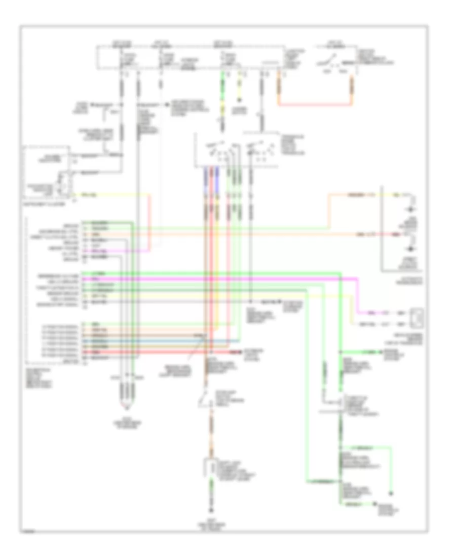
TRANSMISSION
1.3L
1.3L (VIN 2), Transmission Wiring Diagram, 3-Speed Transmission for Chevrolet Metro LSi 1998
List of elements for 1.3L (VIN 2), Transmission Wiring Diagram, 3-Speed Transmission for Chevrolet Metro LSi 1998:
- "2" position signal
- "d" position signal
- "l" position signal
- "n" position signal
- "p" position signal
- "r" position signal
- (dash harn, near breakout to cluster assy)
- (engine harn, near engine compt grommet)
- 2nd brake solenoid
- 2nd brake sol ctrl
- Acc
- Air conditioning, headlights (drl), & engine controls system
- Audio alarm module
- Automatic transmission
- Back fuse 15a
- Direct clutch sol ctrl
- Direct clutch solenoid
- Dome fuse 15a
- Engine controls system
- Engine start signal
- Exterior lights system
- G133 (center rear of engine)
- G407 (center rear of trunk)
- Gauges/ indicators
- Ground
- Hazard switch
- Hot at all times
- Hot in on or start
- Ig-coil fuse 15a
- Ignition
- Ignition switch (right side of steering column)
- Instrument cluster
- Interior lights system
- Junction block (left side of dash)
- Lock
- Malfunction indicator lamp
- Memory power
- Mil ctrl
- Powertrain control module (behind right side of dash)
- Red
- Reference voltage
- Run
- S127 (engine harn, near firewall grommet)
- S130
- S154 (engine harn, near firewall grommet)
- S156 (engine harn, near firewall grommet)
- S158
- S164 (engine harn, 8 cm from map sensor breakout)
- S241
- S242
- S248
- S259 (engine harn, near firewall grommet)
- Sensor ground
- Shift lock solenoid (under floor console, in front of shift lever)
- Start
- Starting/ charging system
- Stoplamp switch (top of brake pedal)
- Throttle position in
- Throttle position sensor (on side of throttle body)
- Transaxle range switch (top of transaxle)
- Vehicle speed sensor (top of transaxle)
- Vss hi (signal)
- Vss lo (ground)
1.3L VIN 2, A/T Wiring Diagram for Chevrolet Metro LSi 1998
List of elements for 1.3L VIN 2, A/T Wiring Diagram for Chevrolet Metro LSi 1998:
- "2" position signal
- "d" position signal
- "l" position signal
- "n" position signal
- "p" position signal
- "r" position signal
- (dash harn, near breakout to cluster assy)
- (engine harn, near engine compt grommet)
- 2nd brake solenoid
- 2nd brake sol ctrl
- Acc
- Air conditioning, headlights (drl), & engine controls system
- Audio alarm module
- Automatic transmission
- Back fuse 15a
- Direct clutch sol ctrl
- Direct clutch solenoid
- Dome fuse 15a
- Engine controls system
- Engine start signal
- Exterior lights system
- G133 (center rear of engine)
- G407 (center rear of trunk)
- Gauges/ indicators
- Ground
- Hazard switch
- Hot at all times
- Hot in on or start
- Ig-coil fuse 15a
- Ignition
- Ignition switch (right side of steering column)
- Instrument cluster
- Interior lights system
- Junction block (left side of dash)
- Lock
- Malfunction indicator lamp
- Memory power
- Mil ctrl
- Powertrain control module (behind right side of dash)
- Red
- Reference voltage
- Run
- S127 (engine harn, near firewall grommet)
- S130
- S154 (engine harn, near firewall grommet)
- S156 (engine harn, near firewall grommet)
- S158
- S164 (engine harn, 8 cm from map sensor breakout)
- S241
- S242
- S248
- S259 (engine harn, near firewall grommet)
- Sensor ground
- Shift lock solenoid (under floor console, in front of shift lever)
- Start
- Starting/ charging system
- Stoplamp switch (top of brake pedal)
- Throttle position in
- Throttle position sensor (on side of throttle body)
- Transaxle range switch (top of transaxle)
- Vehicle speed sensor (top of transaxle)
- Vss hi (signal)
- Vss lo (ground)
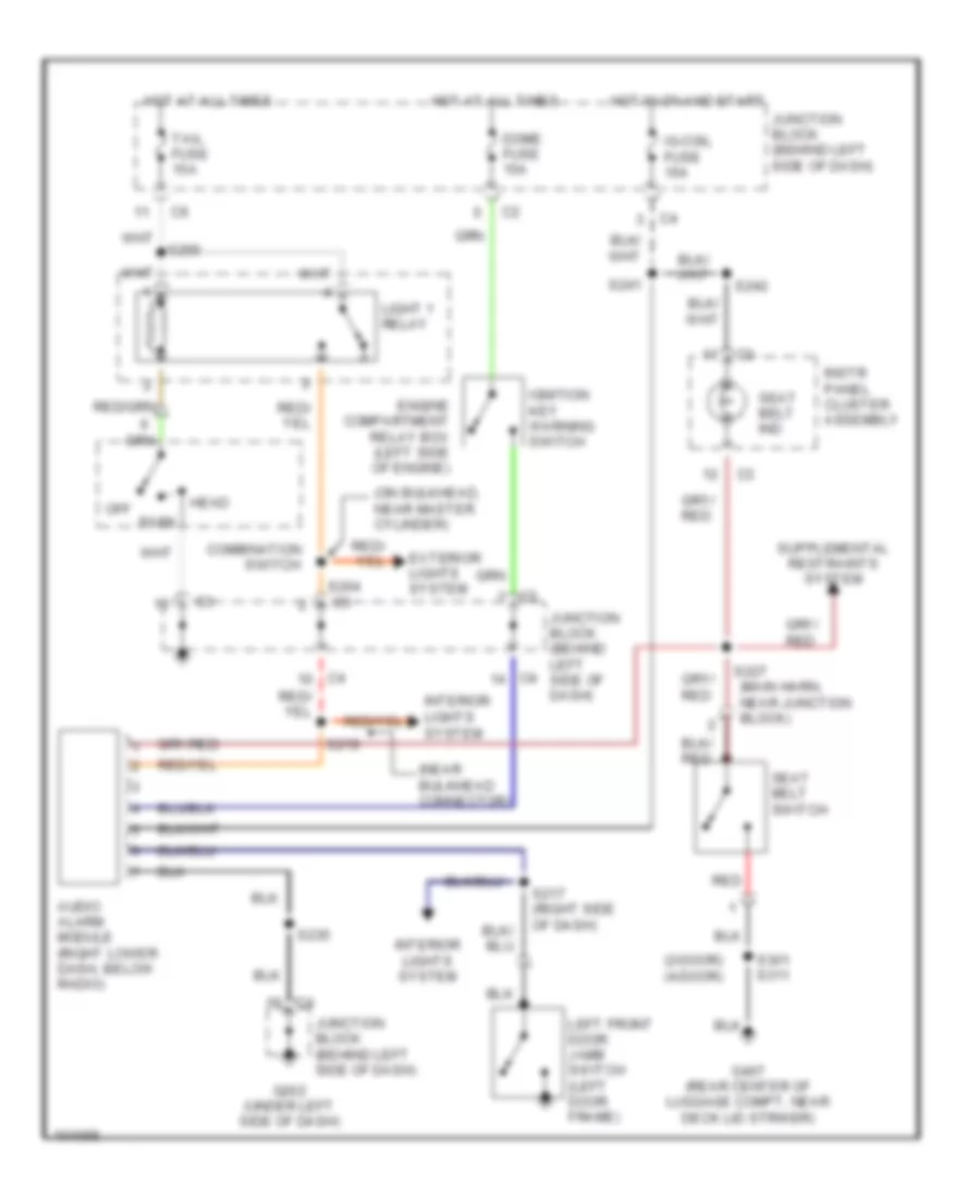
WARNING SYSTEMS
Warning System Wiring Diagrams for Chevrolet Metro LSi 1998
List of elements for Warning System Wiring Diagrams for Chevrolet Metro LSi 1998:
- (2-door) (4-door)
- (near bulkhead connector)
- (on bulkhead, near master cylinder)
- Audio alarm module (right lower dash, below radio)
- Combination switch
- Dome fuse 15a
- Engine compartment relay box (left side of engine)
- Exterior lights system
- G202 (under left side of dash)
- G407 (rear center of luggage compt, near deck lid striker)
- Head
- Hot at all times
- Hot in on and start
- Ig-coil fuse 15a
- Ignition key warning switch
- Instr panel cluster assembly
- Interior lights system
- Junction block (behind left side of dash)
- Left front door jamb switch (left door frame)
- Light 1 relay
- Off park
- Red
- S204
- S217 (right side of dash)
- S219
- S227 (main harn, near junction block)
- S235
- S241
- S242
- S256
- S301 s311
- Seat belt ind
- Seat belt switch
- Tail fuse 15a
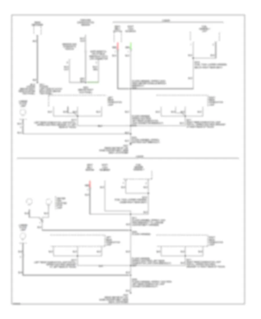
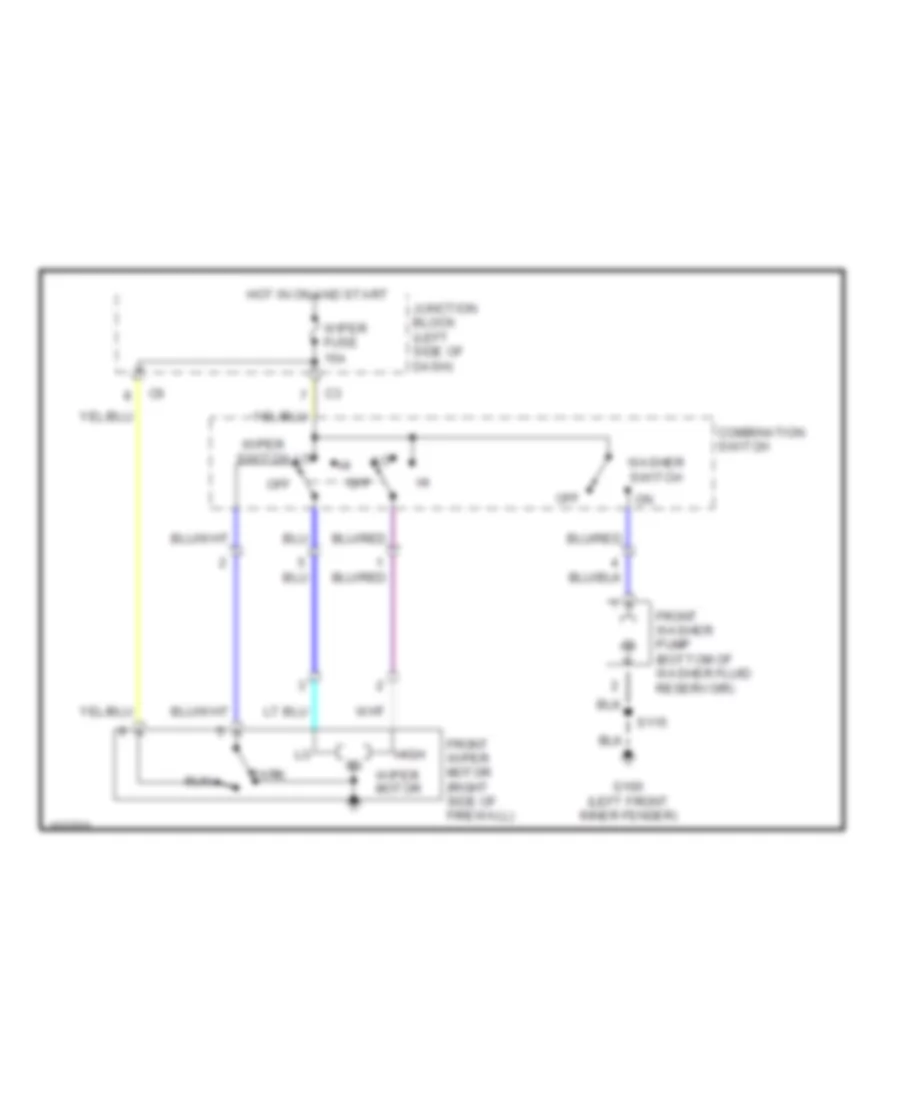
WIPER/WASHER
2-Speed Wiper/Washer Wiring Diagram for Chevrolet Metro LSi 1998
List of elements for 2-Speed Wiper/Washer Wiring Diagram for Chevrolet Metro LSi 1998:
- Combination switch
- Front washer pump (bottom of washer fluid reservoir)
- Front wiper motor (right side of firewall)
- G100 (left front inner fender)
- High
- Hot in on and start
- Junction block (left side of dash)
- Off
- Park
- Run
- S115
- Washer switch
- Wiper fuse 15a
- Wiper motor
- Wiper switch
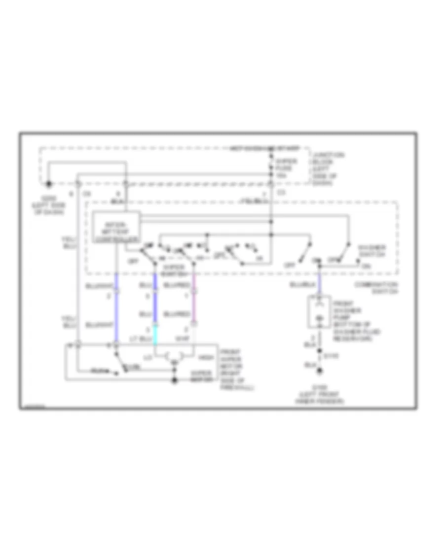
Intermittent Wiper/Washer Wiring Diagram for Chevrolet Metro LSi 1998
List of elements for Intermittent Wiper/Washer Wiring Diagram for Chevrolet Metro LSi 1998:
- Combination switch
- Front washer pump (bottom of washer fluid reservoir)
- Front wiper motor (right side of firewall)
- G100 (left front inner fender)
- G202 (left side of dash)
- High
- Hot in on and start
- Int
- Inter- mittent controller
- Junction block (left side of dash)
- Off
- Park
- Run
- S115
- Washer switch
- Wiper fuse 15a
- Wiper motor
- Wiper switch
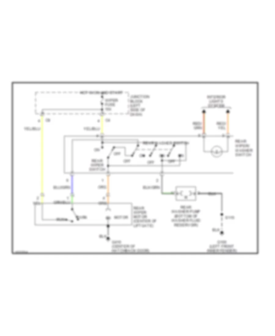
Rear Wiper/Washer Wiring Diagram for Chevrolet Metro LSi 1998
List of elements for Rear Wiper/Washer Wiring Diagram for Chevrolet Metro LSi 1998:
- G100 (left front inner fender)
- G410 (center of hatchback door)
- Hot in on and start
- Interior lights system
- Junction block (left side of dash)
- Motor
- Off
- Park
- Rear washer pump (bottom of washer fluid reservoir)
- Rear washer switch
- Rear wiper motor (center of liftgate)
- Rear wiper switch
- Rear wiper/ washer switch
- Run
- S115
- Wiper fuse 15a

 Čeština
 Dansk
Dansk Deutsch
 Ελληνικά
 English
 English
 Español
 Suomi
Suomi Français
 Français
 עברית
עברית Hrvatski
 Magyar
 Italiano
 日本語
日本語 한국어
한국어 Nederlands
 Polski
 Português
 Română
 Русский
 Slovenčina
 Slovenščina
 Svenska
 Türkçe
 中文 (中国)