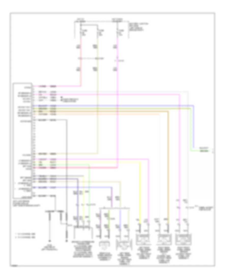
AIR CONDITIONING
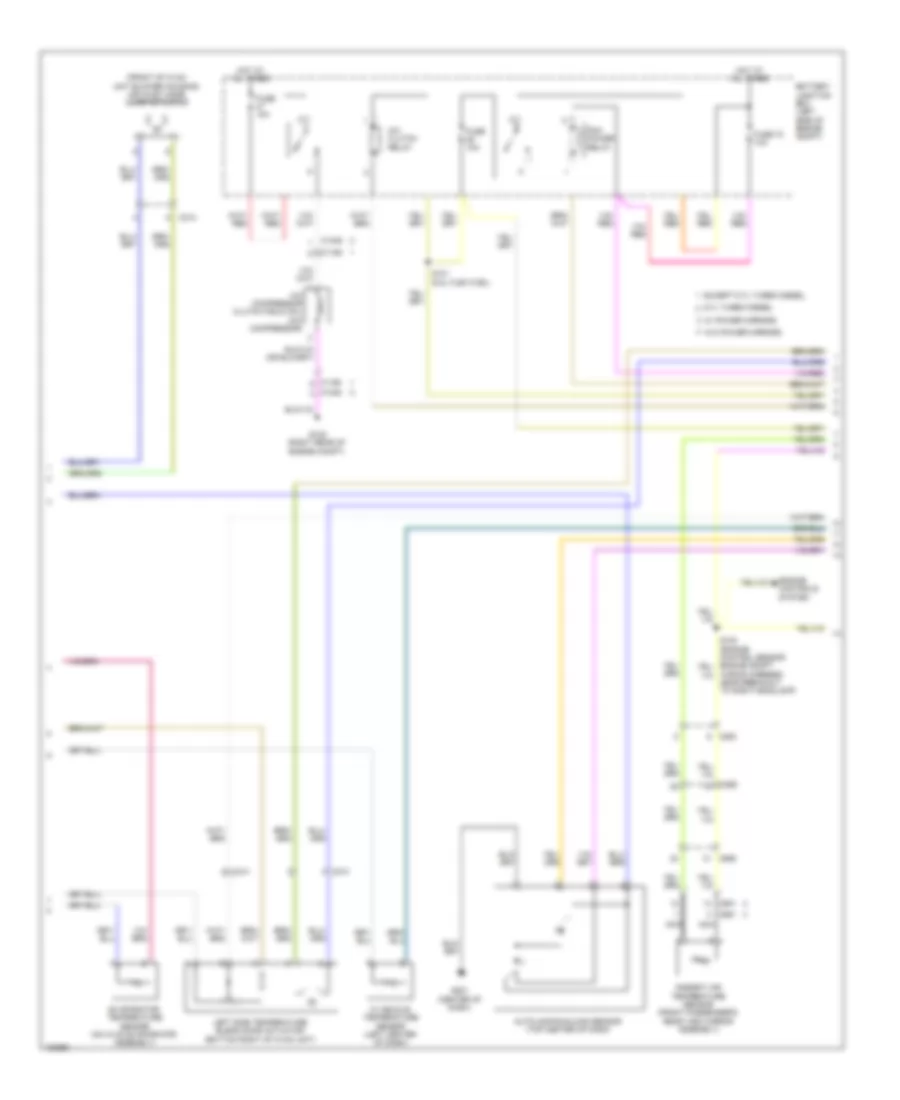
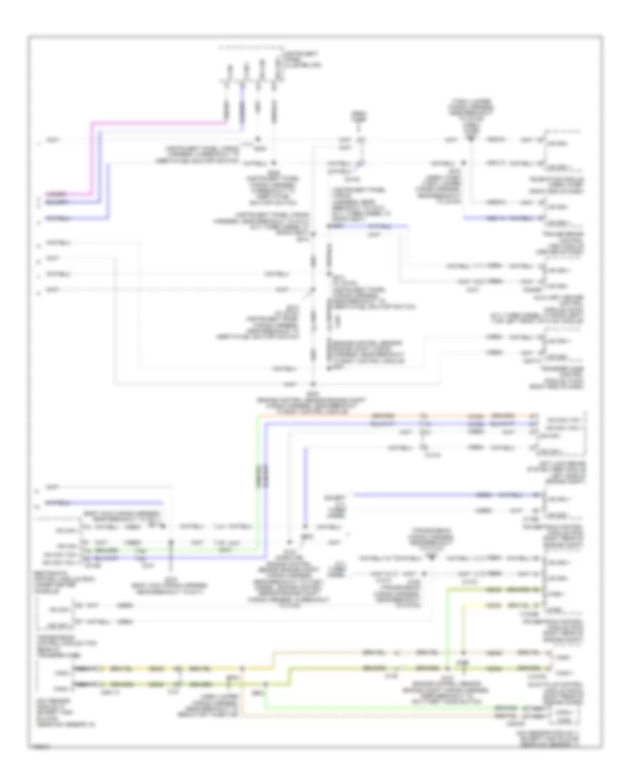
Automatic A/C Wiring Diagram (1 of 3) for Ford F-250 Super Duty King Ranch 2014
 https://portal-diagnostov.com/license.html
Automotive Electricians Portal FZCO
Automotive Electricians Portal FZCO
https://portal-diagnostov.com/license.html
https://portal-diagnostov.com/license.html
Automotive Electricians Portal FZCO
Automotive Electricians Portal FZCO
List of elements for Automatic A/C Wiring Diagram (1 of 3) for Ford F-250 Super Duty King Ranch 2014:
- (center of dash) g201
- (hvac jumper wiring harness, near breakout to evaporator temperature sensor) s251
- (top left front of hvac unit) (diesel w/ rapid heat) auxiliary heater control module (ahcm)
- Autolamp sensor in
- Batt
- Battery
- Battery junction box (bjb) (left side of engine compt)
- Blower motor (right end of hvac unit)
- Blower motor relay
- Blower motor speed control (right front of hvac assembly)
- Body control module (right kick panel)
- C1617e
- C1617f
- C211
- C213
- C214
- C2280a
- C2280b
- C228a
- Cbp37
- Ch122
- Ch123
- Ch202
- Ch203
- Ch207
- Ch208
- Ch238
- Ch239
- Computer data lines system
- Defogger system
- Defrost request
- Defrost/panel/floor mode door actuator (left side of hvac unit)
- Evap temp sensor
- Front blower rly
- Fuse 10a
- Fuse 40a
- G101 (lower right rear of engine)
- G203 (lower left center of dash)
- Gd108
- Gd184
- Gnd
- Harness, near breakout to g201)
- High current battery junction box (bjb) (right side of engine compt)
- Hot at all times
- Hot in start or run
- Hs can+
- Hs can-
- Hvac module
- Lh111
- Mega fuse 125a
- Micro
- Mode 1 act fdbk
- Mode dr 1 ccw
- Mode dr 1 cw
- Motor+
- Motor-
- Ms can+
- Ms can-
- Nca
- Pass temp act fdbk
- Pass temp dr ccw
- Pass temp dr cw
- Pwm
- Recirc ccw
- Recirc cw
- Red
- Return
- Rh111
- Right side temperature blend door actuator (top right side of hvac unit)
- S250 (hvac jumper wiring harness, near breakout to evaporator temperature sensor)
- S257 (hvac jumper wiring harness, near breakout to blower motor)
- Sbp46
- Sdf05
- Variable blower ctrl
- Vbat
- Vdb04
- Vdb05
- Vdb06
- Vdb07
- Vh101
- Vh406
- Vh437
- Vh440
- Vlf14
- Vpwr
- Vref
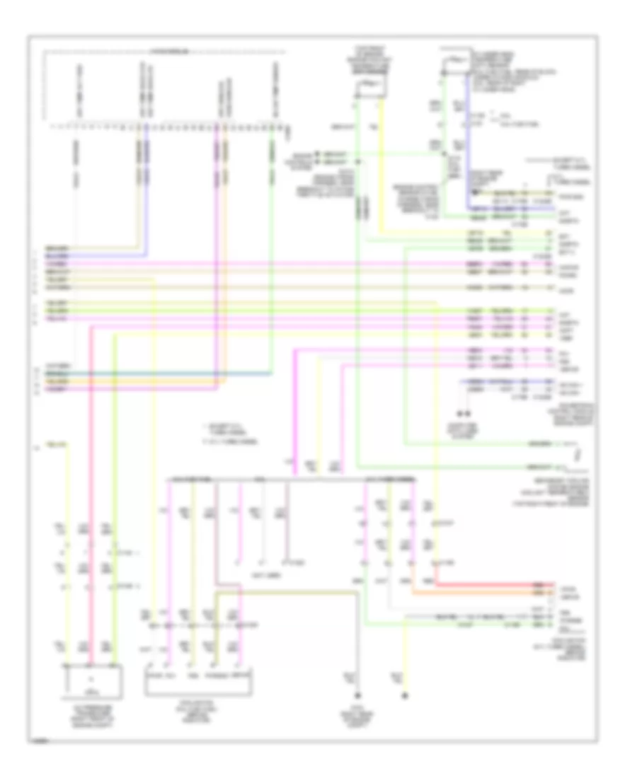
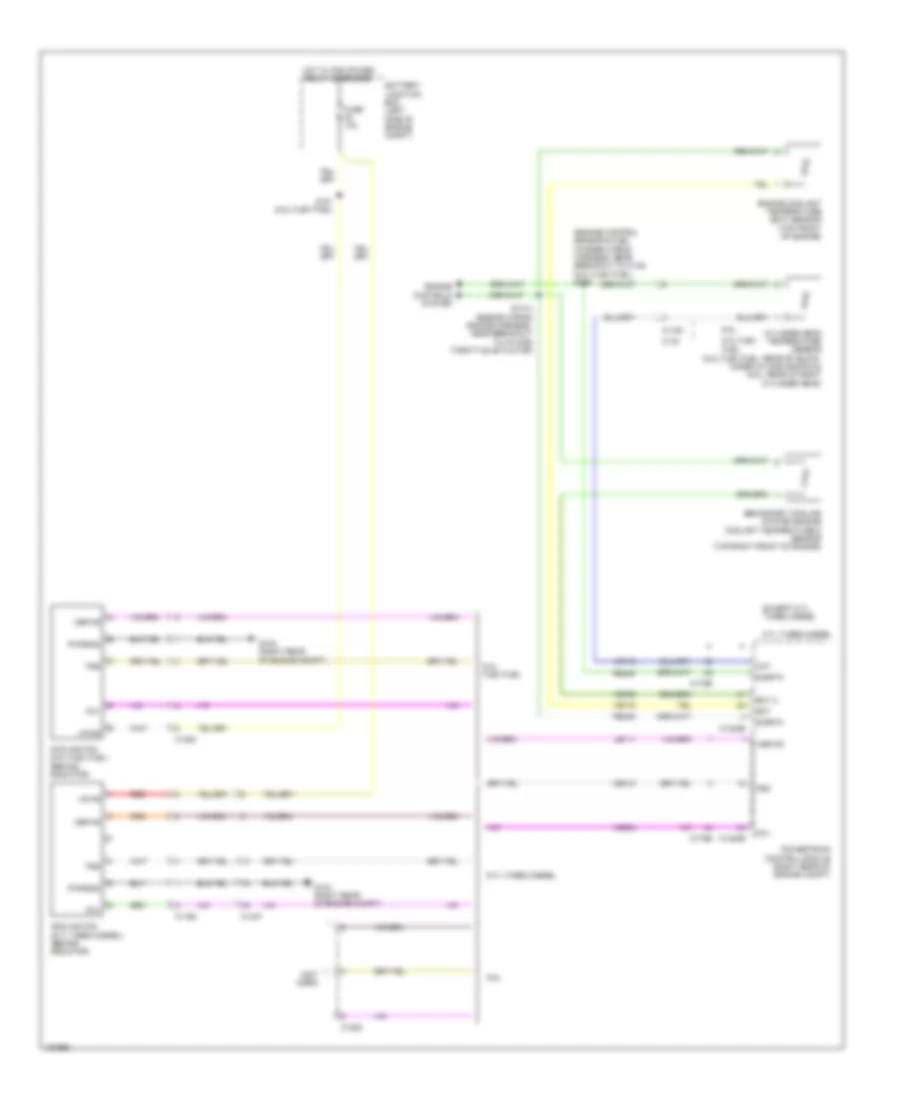
Automatic A/C Wiring Diagram (2 of 3) for Ford F-250 Super Duty King Ranch 2014
List of elements for Automatic A/C Wiring Diagram (2 of 3) for Ford F-250 Super Duty King Ranch 2014:
- (front of hvac unit blower housing) air inlet mode door actuator
- 6.7l turbo diesel
- A/c clutch relay
- A/c compressor clutch field coil (a/c compressor)
- Ambient air temperature sensor (front passenger's rear view mirror assembly)
- Autolamp/sunload sensor (top center of dash)
- Battery junction box (left side of engine compt)
- C1046
- C1168
- C213
- C214
- C263
- C265
- C601
- C651
- C655
- Engine controls system
- Evaporator temperature sensor (on hvac evaporator assembly)
- Except 6.7l turbo diesel
- Fuse 10a
- Fuse 72 10a
- G108 (right rear of engine compt)
- G201 (center of dash)
- Hot at all times
- In vehicle temperature sensor (left center of dash)
- Left side temperature blend door actuator (bottom right of hvac unit)
- Nca
- Pcm power relay
- S101 (6.2l flex fuel)
- W/ power mirrors
- W/o power mirrors
- Wiring harness, near breakout to right headlamp)
Automatic A/C Wiring Diagram (3 of 3) for Ford F-250 Super Duty King Ranch 2014
List of elements for Automatic A/C Wiring Diagram (3 of 3) for Ford F-250 Super Duty King Ranch 2014:
- (engine control sensor & fuel charge wiring harness, near breakout to c133)
- (not used)
- (right rear of engine compt) g103
- (top front of engine) engine coolant temperature (ect) sensor
- 6.2l flex fuel
- 6.7l turbo diesel
- 6.8l
- A/c pressure transducer (right front of engine compt)
- Aat
- Accr
- Acpt
- C1046
- C1047
- C1148
- C1163
- C1165
- C1220
- C1232b
- C1232e
- C133
- C175b
- C175e
- C228b
- Ce237
- Ch212
- Ch213
- Ch302
- Cht
- Computer data lines system
- Cooling fan (6.2l flex fuel) (behind radiator)
- Cooling fan (6.7l turbo diesel) (behind radiator)
- Cylinder head temperature (cht) sensor (6.2l flex fuel: rear of block, under intake manifold) (6.8l: rear of right cylinder head)
- Drv sunload
- Drv temp act fdbk
- Drv temp door ccw
- Drv temp door cw
- Ect
- Ect 2
- Engine controls system
- Except 6.7l
- Except 6.7l turbo diesel
- Fcv
- Fss
- G103 (right rear of engine compt)
- Gd113
- Hs can +
- Hs can -
- Hvac module
- In car temp sensor
- Kapwr
- Le111
- Le424
- Pass sunload
- Pcmrc
- Powertrain control module (right rear of engine compt)
- Pwr gnd
- Pwrgnd
- Re405
- Re407
- Red
- S116 (6.2l flex fuel)
- Sbb72
- Secondary cooling system engine coolant temperature 2 sensor (top right front of engine)
- Sigrtn
- Turbo diesel
- Vbpwr
- Vdb04
- Vdb05
- Ve203
- Ve712
- Ve716
- Ve759
- Vec10
- Vh407
- Vh414
- Vh416
- Vh417
- Vh433
- Vh441
- Vpwr
- Vref
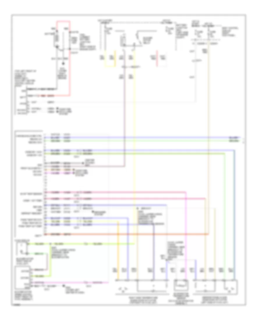
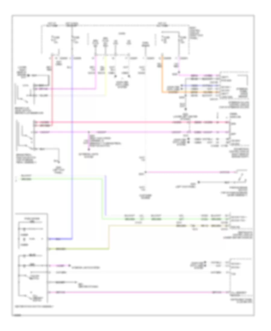
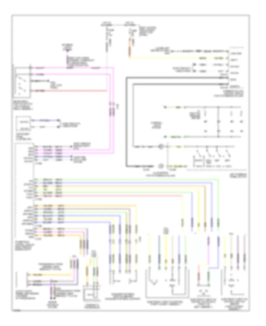
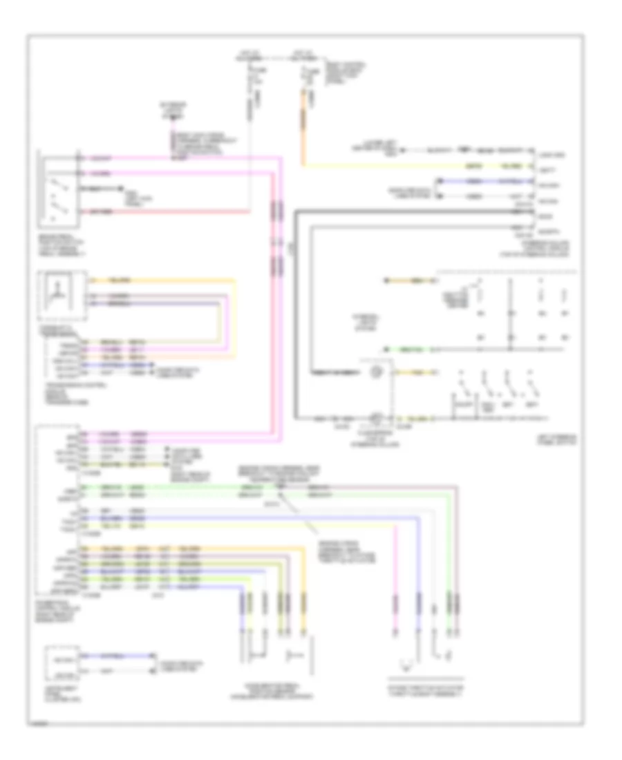
Manual A/C Wiring Diagram (1 of 2) for Ford F-250 Super Duty King Ranch 2014
List of elements for Manual A/C Wiring Diagram (1 of 2) for Ford F-250 Super Duty King Ranch 2014:
- (center of dash) g201
- (top left front of hvac unit) (diesel w/ rapid heat) auxiliary heater control module (ahcm)
- Batt
- Battery
- Battery junction box (left side of engine compt)
- Blower motor (right end of hvac unit)
- Blower motor relay
- Blower motor speed control (right front of hvac assembly)
- Body control module (right kick panel)
- C1617e
- C1617f
- C211
- C213
- C214
- C2280a
- C2280b
- Cbp37
- Ch122
- Ch123
- Ch202
- Ch203
- Ch207
- Ch208
- Ch238
- Ch239
- Computer data lines system
- Defogger system
- Defrost request
- Defrost/panel/floor mode door actuator (left side of hvac unit)
- Evap temp sensor
- Evaporator temperature sensor (on hvac evaporator assembly)
- Front blower rly
- Fuse 10a
- Fuse 40a
- G101 (lower right rear of engine)
- G203 (lower left center of dash)
- Gd108
- Gd184
- Gnd
- High current battery junction box (right side of engine compt)
- Hot at all times
- Hot in start or run
- Hs can+
- Hs can-
- Hvac module
- Lh111
- Mega fuse 125a
- Mode 1 act fdbk
- Mode dr 1 ccw
- Mode dr 1 cw
- Motor+
- Motor-
- Ms can+
- Ms can-
- Nca
- Pass temp act fdbk
- Pass temp dr ccw
- Pass temp dr cw
- Pwm
- Recirc ccw
- Recirc cw
- Red
- Return
- Rh111
- Right side temperature blend door actuator (top right of hvac unit)
- S250 (hvac jumper wiring harness, near breakout to evaporator temperature sensor)
- S257 (hvac jumper wiring harness, near breakout to blower motor)
- Sbp46
- Sdf05
- Variable blower ctrl
- Vbatt
- Vdb04
- Vdb05
- Vdb06
- Vdb07
- Vh101
- Vh406
- Vh437
- Vh440
- Vpwr
- Vref
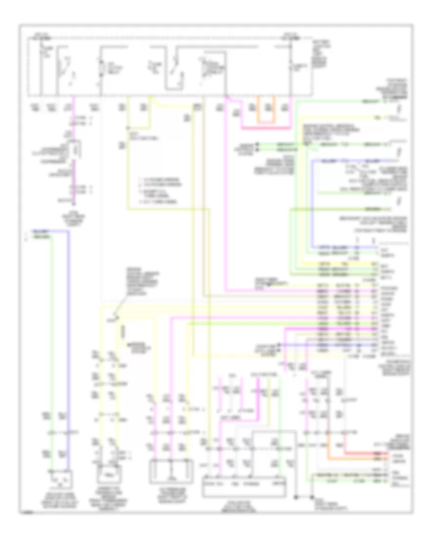
Manual A/C Wiring Diagram (2 of 2) for Ford F-250 Super Duty King Ranch 2014
List of elements for Manual A/C Wiring Diagram (2 of 2) for Ford F-250 Super Duty King Ranch 2014:
- (behind radiator) (6.7l turbo diesel) cooling fan
- (engine control sensor & fuel charge wiring harness, near breakout to c133) (6.2l flex fuel) s116
- (engine control sensor engine compt wiring harness, near breakout to right headlamp)
- (not used)
- (right rear of engine compt) g103
- (top front of engine) engine coolant temperature (ect) sensor
- 6.2l flex fuel
- 6.7l turbo diesel
- 6.8l
- A/c clutch relay
- A/c compressor clutch field coil (a/c compressor)
- A/c pressure transducer (right front of engine compt)
- Aat
- Accr
- Acpt
- Air inlet mode door actuator (front of hvac unit blower housing)
- Ambient air temperature sensor (front passenger's rear view mirror assembly)
- Battery junction box (left side of engine compt)
- C1046
- C1047
- C1148
- C1163
- C1165
- C1168
- C1220
- C1232b
- C1232e
- C133
- C175b
- C175e
- C213
- C263
- C265
- C601
- C651
- C655
- Ce237
- Ch302
- Cht
- Computer data lines system
- Cooling fan (6.2l flex fuel) (behind radiator)
- Cylinder head temperature sensor (6.2l flex fuel: rear of block, under intake manifold) (6.8l: rear of right cylinder head)
- Ect
- Ect 2
- Engine controls system
- Except 6.7l
- Fcv
- Fss
- Fuse 10a
- Fuse 72 10a
- G103 (right rear of engine compt)
- G108 (right rear of engine compt)
- Gd113
- Hot at all times
- Hs can +
- Hs can -
- Kapwr
- Le111
- Le424
- Nca
- Pcm power relay
- Pcmrc
- Powertrain control module (right rear of engine compt)
- Pwr gnd
- Pwrgnd
- Re405
- Re407
- Red
- S100
- S101 (6.2l flex fuel)
- S1013 (engine wiring harness, near breakout to intake throttle actuator)
- Sbb72
- Secondary cooling system engine coolant temperature 2 sensor (top right front of engine)
- Sigrtn
- Turbo diesel
- Vbpwr
- Vdb04
- Vdb05
- Ve203
- Ve712
- Ve716
- Ve759
- Vec10
- Vh407
- Vh433
- Vpwr
- Vref
- W/ power mirrors
- W/o power mirrors
ANTI-LOCK BRAKES
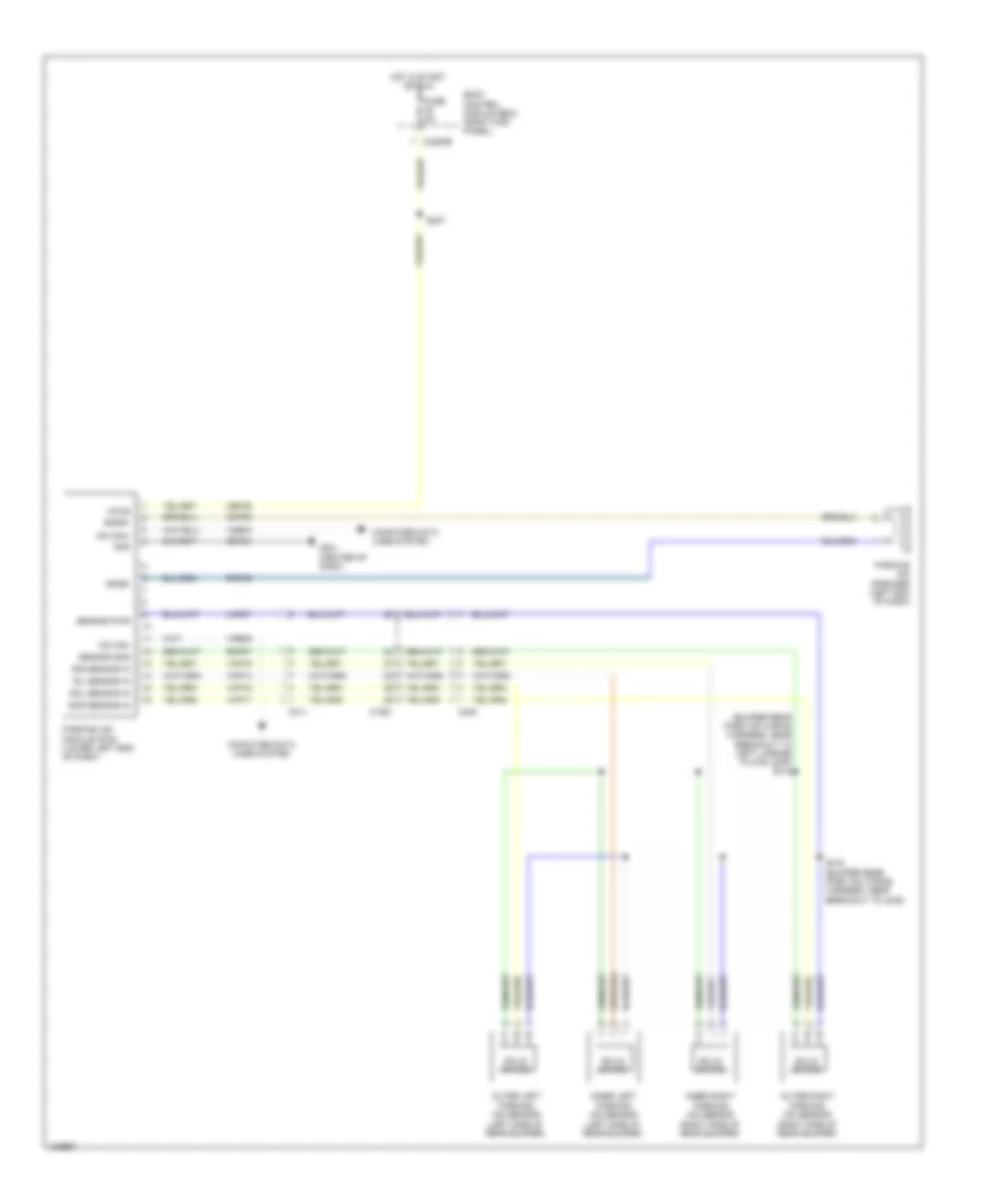
Anti-lock Brakes Wiring Diagram (1 of 2) for Ford F-250 Super Duty King Ranch 2014
List of elements for Anti-lock Brakes Wiring Diagram (1 of 2) for Ford F-250 Super Duty King Ranch 2014:
- Anti-lock brake system module (left side of engine compt)
- Battery junction box (bjb) (left side of engine compt)
- Bpt gnd
- Bpt sense
- Bpt sub
- Brake fluid pressure transducer (w/ 3 channel abs) brake booster vacuum sensor (w/ 4 channel abs) (on brake vacuum booster assembly)
- C110
- C1415
- C1581
- C438
- Cbb54
- Computer data lines system
- Diesel
- Diesel except high sulfur
- Fuse 10a
- Fuse 25a
- Fuse 50a
- G135 (center of left frame rail)
- Gd163
- Hc can +
- Hc can -
- Hot at all times
- Hot in run or start
- Hs can yaw +
- Hs can yaw -
- Lca16
- Left front wheel speed sensor (on left front wheel hub assembly)
- Left rear wheel speed sensor (on left rear wheel hub assembly)
- Lf sensor hi
- Lf sensor lo
- Logic gnd
- Lr sensor hi dss+
- Lr sensor lo dss-
- Motor gnd
- Mtr b+
- Nca
- Rca16
- Rca17
- Rca19
- Rca20
- Rca21
- Rear axle speed sensor (differential assembly)
- Rf sensor hi
- Rf sensor lo
- Right front wheel speed sensor (on right front wheel hub assembly)
- Right rear wheel speed sensor (w/ 4 channel abs) (on right rear wheel hub assembly)
- Rr sensor hi
- Rr sensor lo
- S170
- Sbb86
- Sbb96
- Valve b+
- Vca03
- Vca05
- Vca06
- Vca07
- Vca13
- Vca23
- Vca24
- Vdb04
- Vdb05
- Vpwr
- W/ 3 channel abs
- W/ 4 channel abs
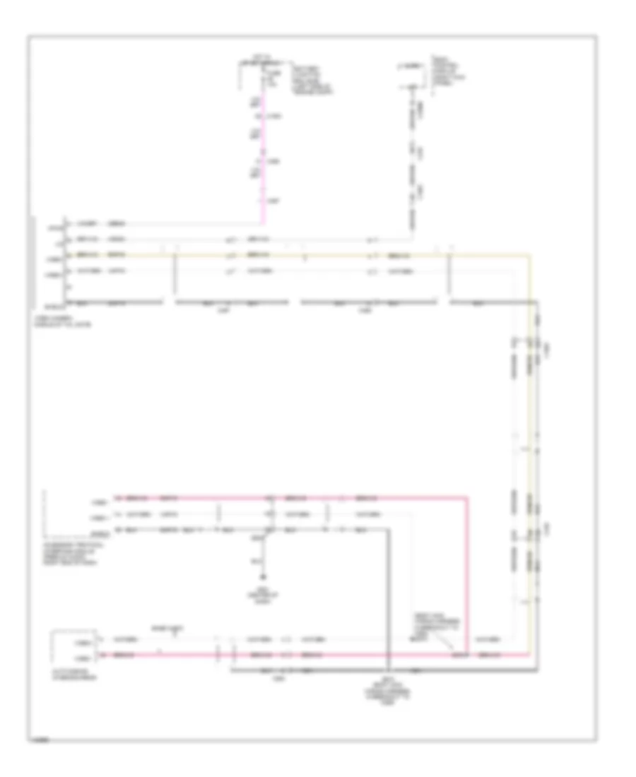
Anti-lock Brakes Wiring Diagram (2 of 2) for Ford F-250 Super Duty King Ranch 2014
List of elements for Anti-lock Brakes Wiring Diagram (2 of 2) for Ford F-250 Super Duty King Ranch 2014:
- (lower right rear of engine) g101
- (not used)
- Amber
- Body control module (right kick panel)
- Bpp
- Bps
- Brake fluid level switch (brake fluid reservoir)
- Brake pedal position switch (top of brake pedal assembly)
- Brk fluid sw
- Brk fluid sw rtn
- C1232b
- C1415
- C175b
- C210
- C212
- C2280a
- C2280b
- C2280c
- C2280d
- C2280f
- C2414a
- C2414b
- C310a
- C310b
- Ccb08
- Center stack switch assembly
- Ces09
- Cmc19
- Cmc25
- Computer data lines system
- Customer access
- Diesel
- Exterior lights system
- Fuse 10a
- Fuse 15a
- Fuse 5a
- Fuse 7.5a
- G201 (center of dash)
- G202 (lower left center of dash)
- G300 (left kick panel)
- Gasoline
- Gd185
- Hill descent switch
- Hot at all times
- Hot in run or start
- Hs can +
- Hs can -
- Hs can yaw +
- Hs can yaw -
- Hs can+
- Hs can-
- Instrument panel cluster (ipc)
- Interior lights system
- Logic gnd
- Micro
- Pad ind
- Park brake
- Parking brake switch (top of parking brake lever assembly)
- Pass air bag off
- Powertrain control module (right rear of engine compt)
- Pwr gnd
- Red
- Restraints control module (under center console)
- Rmc19
- Rr116
- S207 (body main wiring harness, in breakout to brake pedal position switch)
- S228
- S239
- S304
- Sbp24
- Sbp26
- Steering column control module (top of steering column)
- Steering wheel angle sensor
- Tcs
- Tcs off switch
- Vbatt
- Vca23
- Vca24
- Vdb04
- Vdb05
ANTI-THEFT
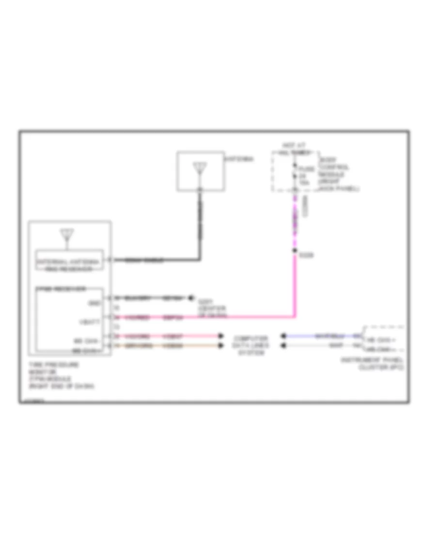
Forced Entry Wiring Diagram (1 of 2) for Ford F-250 Super Duty King Ranch 2014
List of elements for Forced Entry Wiring Diagram (1 of 2) for Ford F-250 Super Duty King Ranch 2014:
- (body main wiring harness, near breakout to c312) (crew cab) s382
- (body main wiring harness, near breakout to c312) s302
- (body main wiring harness, near breakout to c312) s305
- Accessory delay relay
- All lock/ unlock relay
- Body control module (right kick panel)
- C2280c
- C2280d
- C555
- C655
- C755
- C855
- Computer data lines system
- Cpk19
- Cpk23
- Door lock
- Door unlock
- Driver door unlock relay
- Driver side door lock switch
- Fuse 15a
- Fuse 20a
- G300 (left kick panel)
- G302 (right kick panel)
- Hot at all times
- Internal antenna rke receiver
- Left front door lock actuator
- Left rear door lock actuator (crew cab)
- Lock
- Micro
- Ms can +
- Ms can -
- Passenger side door lock switch
- Right front door lock actuator
- Right rear door lock actuator (crew cab)
- S306 (body main wiring harness, near breakout to c312)
- S314
- S505 (w/ power equipment)
- S638 (w/ power equipment)
- Tire pressure monitor module (right end of dash)
- Unlock
- Vdb06
- Vdb07
Forced Entry Wiring Diagram (2 of 2) for Ford F-250 Super Duty King Ranch 2014
List of elements for Forced Entry Wiring Diagram (2 of 2) for Ford F-250 Super Duty King Ranch 2014:
- (left kick panel) g300
- (w/ power equipment) s505
- 1/2
- 3/4
- 5/6
- 7/8
- 9/0
- Anti-theft hood switch (left front of engine compt)
- Body control module (right kick panel)
- C2280b
- C2280c
- C2280f
- C2414a
- C555
- C655
- C755
- C756
- C855
- C856
- Clf24
- Computer data lines system
- Cpk29
- Cpk30
- Cpk31
- Cpl25
- Cpl26
- Cpl31
- Cpl36
- Cpl39
- Crew cab
- Crh04
- Driver side front door ajar switch (lower rear of driver side front door)
- Driver side rear door ajar switch (super cab & crew cab) (crew cab: lower rear of driver side rear door) (super cab: lower front of driver side rear door)
- Fuse 10a
- G104 (left rear of engine compt)
- G300 (left kick panel)
- G302 (right kick panel)
- Hdlp on
- Headlights system
- Hood ajar
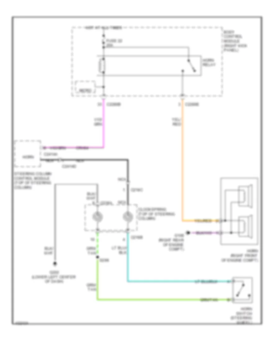
- Horn
- Horns system
- Hot at all times
- Hs can +
- Hs can -
- Keyless entry keypad
- Keypad illum (fet)
- Keypad sw a
- Keypad sw b
- Keypad sw c
- Lf door ajar
- Lr door ajar
- Micro
- Ms can +
- Ms can -
- Passenger side front door ajar switch (lower rear of passenger side front door)
- Passenger side rear door ajar switch (super cab & crew cab) (crew cab: lower rear of passenger side rear door) (super cab: lower front of passenger side rear door)
- Rf door ajar
- Rr door ajar
- S505
- S638
- S700
- S802
- Steering column control module (top of steering column)
- Super cab
- Vdb04
- Vdb05
- Vdb06
- Vdb07
- W/ heated rear seats
- W/ power equipment
- W/o heated rear seats
- W/o power equipment
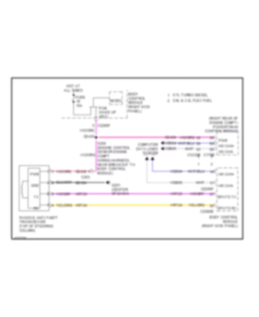
Passive Anti-theft Wiring Diagram for Ford F-250 Super Duty King Ranch 2014
List of elements for Passive Anti-theft Wiring Diagram for Ford F-250 Super Duty King Ranch 2014:
- (right rear of engine compt) powertrain control module
- 6.7l turbo diesel
- 6.8l & 3.2l flex fuel
- Body control module (right kick panel)
- C1232b
- C175b
- C2280b
- C2280f
- C263
- Ce436
- Computer data lines system
- Epats rx
- Epats tx
- Fuse 10a
- G201 (center of dash)
- Gd184
- Gnd
- Hot at all times
- Hs can+
- Hs can-
- Micro
- Passive anti-theft transceiver (top of steering column)
- Pcm wake up (fet)
- Pwr
- Vdb04
- Vdb05
- Vrt23
- Vrt24
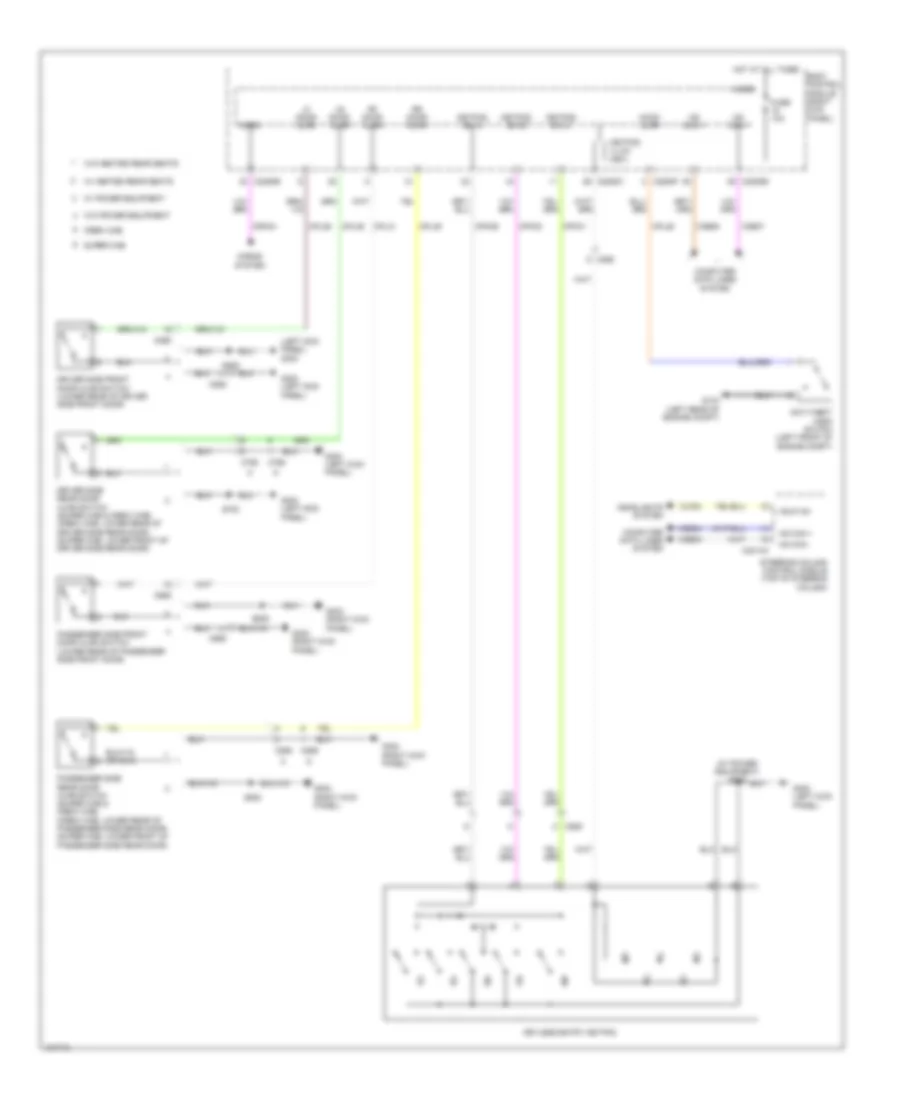
BODY CONTROL MODULES
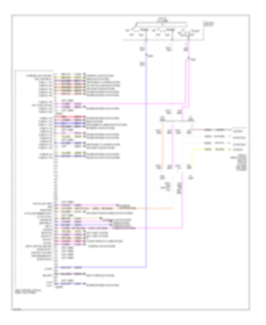
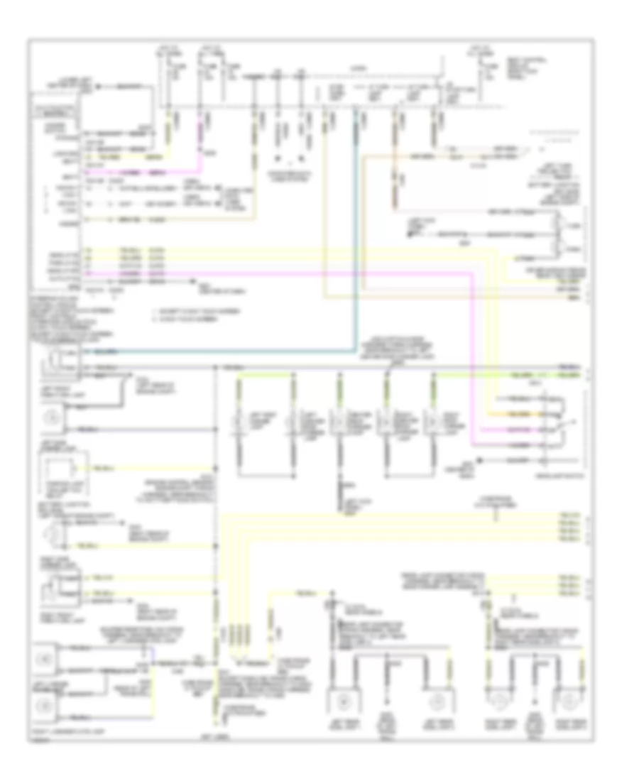
Body Control Modules Wiring Diagram (1 of 2) for Ford F-250 Super Duty King Ranch 2014
List of elements for Body Control Modules Wiring Diagram (1 of 2) for Ford F-250 Super Duty King Ranch 2014:
- (not used)
- (or cdc62)
- (or cdc63)
- Acc
- Acc/run
- Air conditioning & headlights systems
- Air conditioning system
- Anti-theft system
- Autolamp sensor input
- Back lighting led (fet)
- Body control module (right kick panel)
- Bpp
- Bsi (fet)
- C2280a
- C2280b
- Cbp31
- Cbp32
- Cbp34
- Cbp35
- Cbp36
- Cbp37
- Cbp38
- Cbp41
- Cbp44
- Ccb08
- Cdc30
- Cdc33
- Cdc34
- Cdc35
- Cdc62
- Cdc63
- Cet53
- Circuit deactivation ignition module (w/ cdim) (left end of dash)
- Clf12
- Cls32
- Clutch input
- Computer data lines system
- Crh04
- Epats rx
- Epats tx
- Exterior lights system
- Fog lamp relay
- Fuse 11, 10a
- Fuse 23, 15a
- Fuse 24, 15a
- Fuse 26, 5a
- Fuse 27, 20a
- Fuse 28, 15a
- Fuse 29, 20a
- Fuse 31, 5a
- Fuse 32, 15a
- Fuse 34, 10a
- Fuse 35, 5a
- Fuse 36, 10a
- Fuse 37, 10a
- Fuse 38, 10a
- Fuse 41, 7.5a
- Fuse 42, 5a
- Fuse 44, 10a
- Fuse 45, 5a
- Fuse 46, 10a
- Fuse 9, 10a
- Hazard sw
- Headlights system
- Horn relay
- Horns system
- Hot at all times
- Hot in run or acc
- Ignition switch
- Instrument cluster system
- Interior lighting (fet)
- Interior lights system
- Key in
- Lin 01
- Lin 04
- Ms can +
- Ms can -
- Navigation & sound systems
- Off
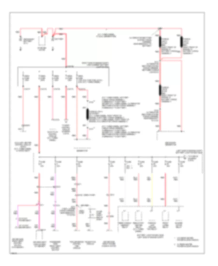
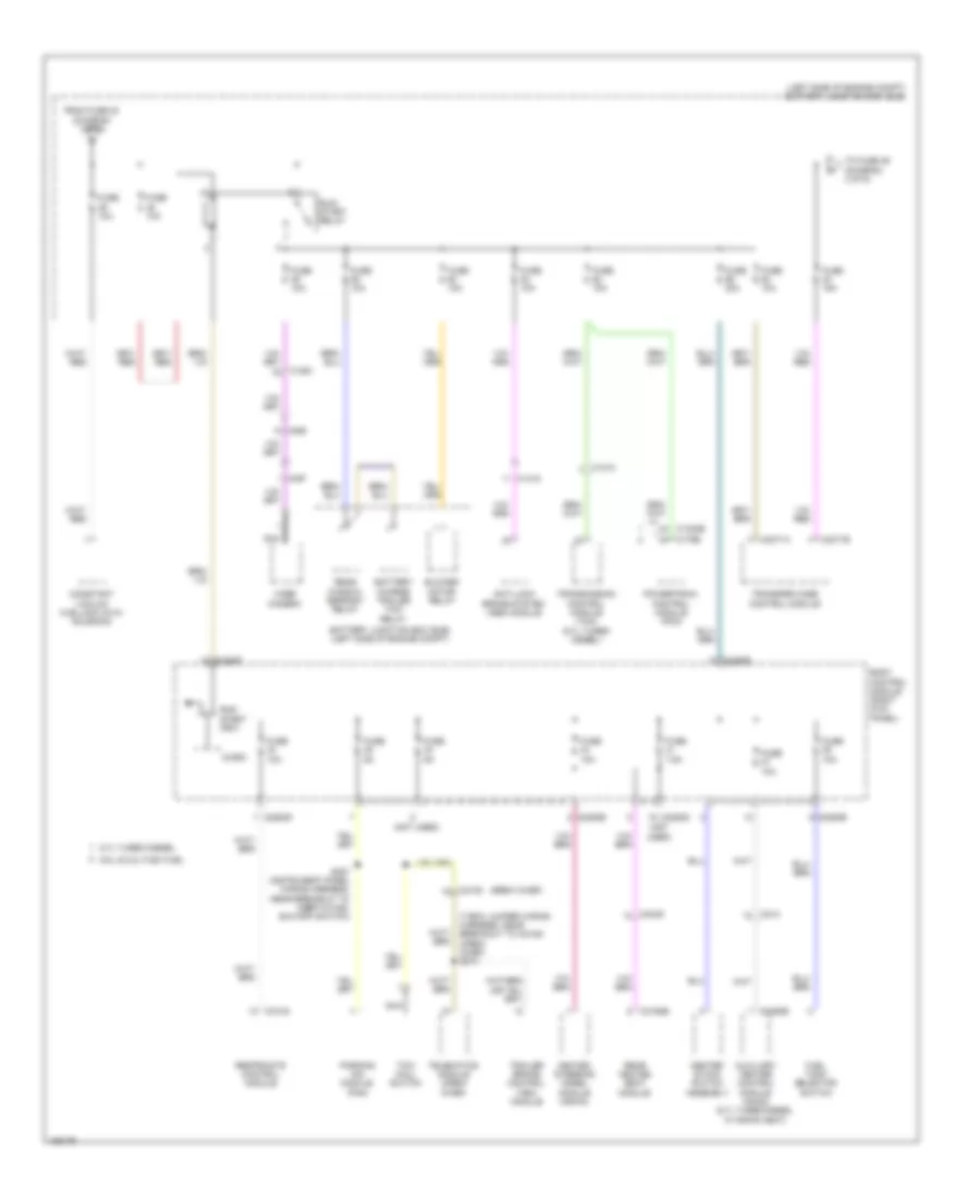
- Power distribution system
- Red
- Ripcord security
- Run
- Run/start
- S284
- S285
- Sbp09
- Sbp11
- Sbp24
- Sbp26
- Sbp28
- Sbp29
- Sbp46
- Seats system
- Shift interlock system
- Sound & navigation systems
- Start
- Start/run
- Start/stop 1
- Start/stop 2
- Strt button (fet)
- Vdb06
- Vdb07
- Vdn01
- Vlf14
- Vln04
- Vln33
- Vrt23
- Vrt24
- W/ cdim
- W/o cdim
- Warning & shift interlock systems
- White light (fet)
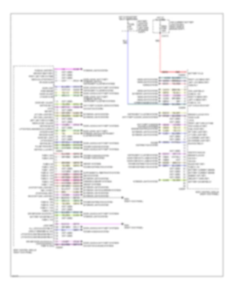
Body Control Modules Wiring Diagram (2 of 2) for Ford F-250 Super Duty King Ranch 2014
List of elements for Body Control Modules Wiring Diagram (2 of 2) for Ford F-250 Super Duty King Ranch 2014:
- (not used)
- 3rd row seat (fet)
- All lock/unlock relay
- Anti-theft & door locks systems
- Anti-theft & engine controls systems engine controls system
- Battery current sense
- Battery junction box (bjb) (left side of engine compt)
- Battery plus
- Battery saver relay
- Body control module (right kick panel)
- Brake fluid sw
- Brake fluid sw rtn
- Bsi (fet)
- C1617c
- C2280c
- C2280d
- C2280e
- C2280f
- C2280g
- Cbb56
- Cbp01
- Cbp30
- Cbp31
- Cbp32
- Cbp33
- Cbp34
- Cbp40
- Cbp43
- Cdc55
- Cdc64
- Ce226
- Ce436
- Circuit breaker 48, 30a
- Clf02
- Clf03
- Clf04
- Clf05
- Clf12
- Cln09
- Cln25
- Cls18
- Cls19
- Cls21
- Cls23
- Cls25
- Cls27
- Cls28
- Cls52
- Cmc19
- Cmc25
- Computer data lines system
- Cpk19
- Cpk23
- Cpk28
- Cpk29
- Cpk30
- Cpk31
- Cpl11
- Cpl25
- Cpl26
- Cpl31
- Cpl36
- Cpl39
- Cpl51
- Cpl52
- Cpw73
- Decklid key unlock
- Decklid/liftgate sw
- Door key lock
- Door key unlock
- Door lock
- Door locks & anti-theft systems
- Door locks, anti-theft, interior lights & instrument cluster systems
- Door unlock
- Driver door unlock & all lock/unlock rly fuse 19, 20a
- Driver door unlock rly
- Energy mgt (fet)
- Exterior lights & mirrors systems
- Exterior lights system
- Fog lamp relay
- Front led turn outage
- Fuel pump (fet)
- Fuse 1, 30a
- Fuse 2, 15a
- Fuse 20a
- Fuse 21, 10a
- Fuse 3, 30a
- Fuse 30, 15a
- Fuse 31, 5a
- Fuse 32, 15a
- Fuse 33, 10a
- Fuse 34, 10a
- Fuse 4, 10a
- Fuse 40, 10a
- Fuse 41, 7.5a
- Fuse 43, 10a
- Fuse 5, 20a
- Fuse 6, 5a
- Fuse 7, 7.5a
- Fuse 8, 10a
- Fuse 9, 10a
- G302 (right kick panel)
- Gd179
- Gnd
- Gnd rtn analog
- Headlights system
- High current battery junction box (right side of engine compt)
- Hood ajar
- Horn rly
- Horns system
- Hot at all times
- Hot in run or start
- Hot w/ run/start relay energized
- Hs can +
- Hs can -
- Instrument cluster system
- Interior lights system
- Keypad illum (fet)
- Keypad sw a
- Keypad sw b
- Keypad sw c
- Left hi beam (fet)
- Left led turn outage
- Left low beam (fet)
- Lf door ajar
- Lf turn lamp (fet)
- Lh corner lamp (fet)
- Liftgate glass release relay
- Liftgate sw
- Liftgate/glass/decklid ajar sw
- Lin 02
- Lin 03
- Logic gnd
- Lr door ajar
- Lr stop/turn lamp (fet)
- Lr turn lamp (fet)
- Mega fuse 125a
- Memory systems
- Mirrors & memory systems
- Navigation & sound systems
- Navigation system
- Park brake
- Pcm wake up (fet)
- Power distribution system
- Power tops system
- Power windows system
- Puddle lamp (fet)
- Pulse train (fet)
- Red
- Rev lp (fet)
- Rf door ajar
- Rf turn lamp (fet)
- Rh corner lamp (fet)
- Right hi beam (fet)
- Right led turn outage
- Right low beam (fet)
- Rmc19
- Rr door ajar
- Rr stop/turn lamp (fet)
- Rr turn lamp (fet)
- Run/acc relay
- Run/start (fet)
- Sbf03
- Sbp02
- Sbp03
- Sbp05
- Sbp06
- Sbp07
- Sbp08
- Sbp19
- Sbp21
- Seats system
- Security horn (fet)
- Srh01
- Stop/chmsl (fet)
- Vdb04
- Vdb05
- Vdn03
- Wiper/washer system
COMPUTER DATA LINES
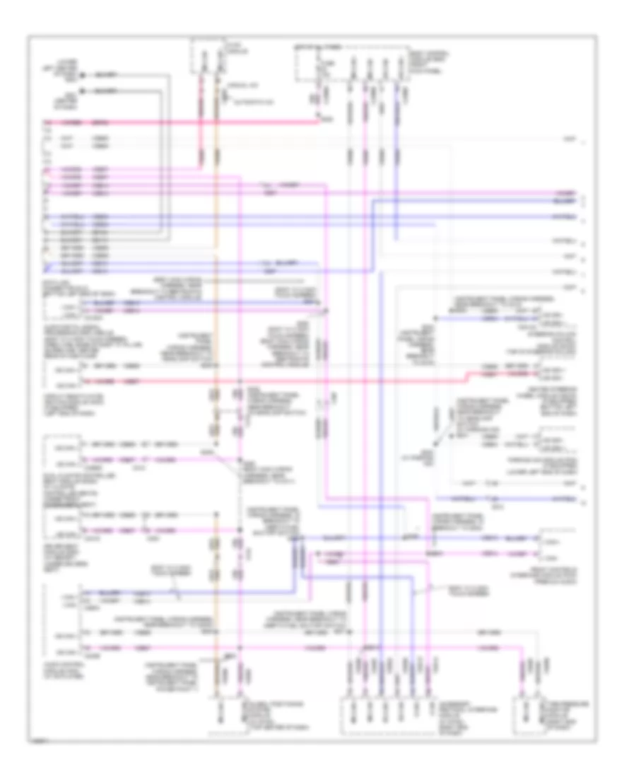
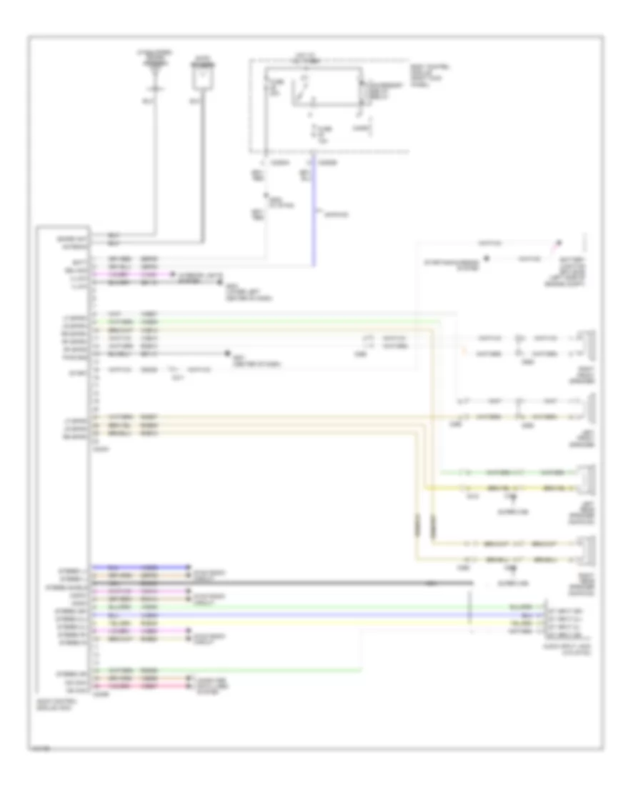
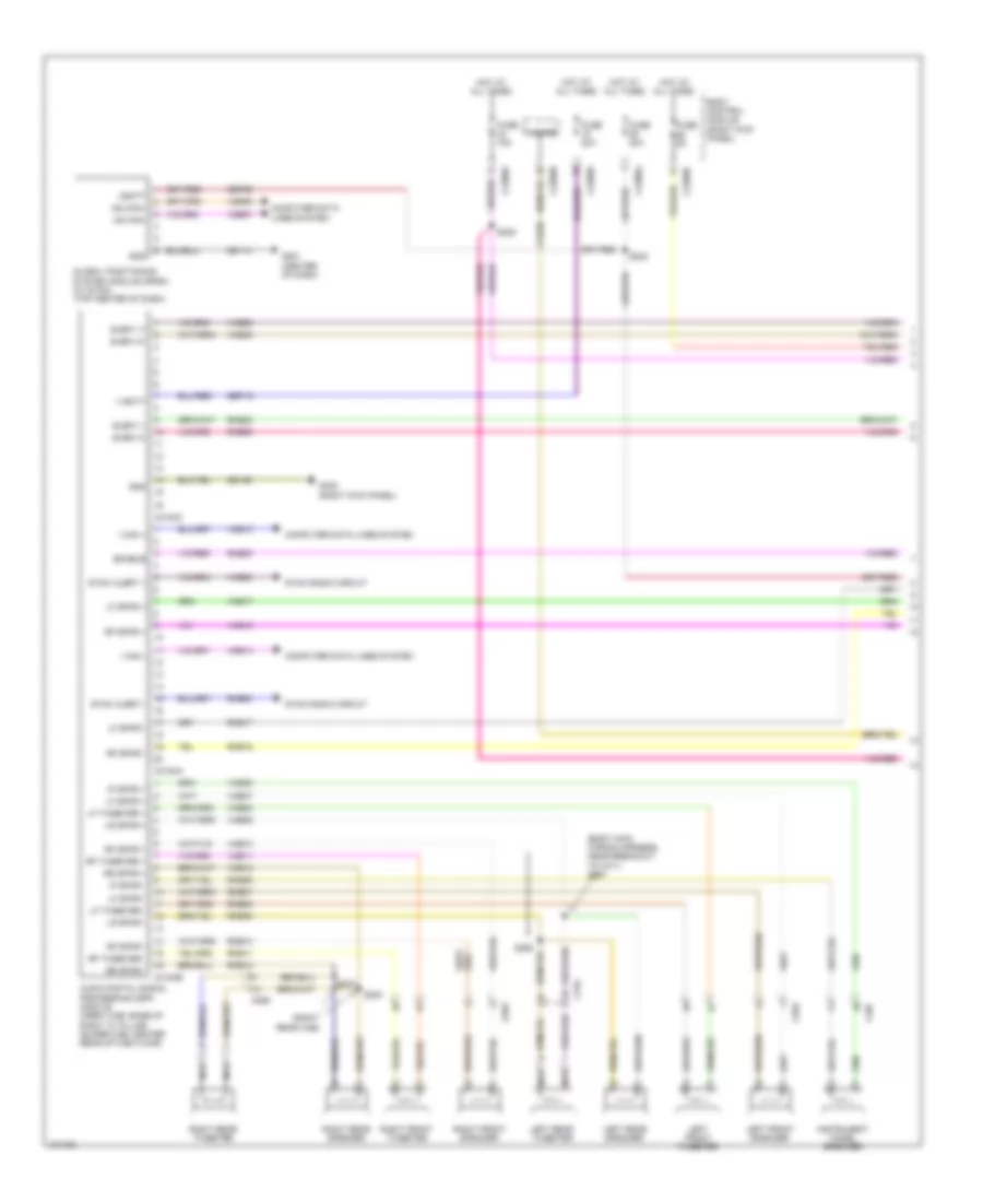
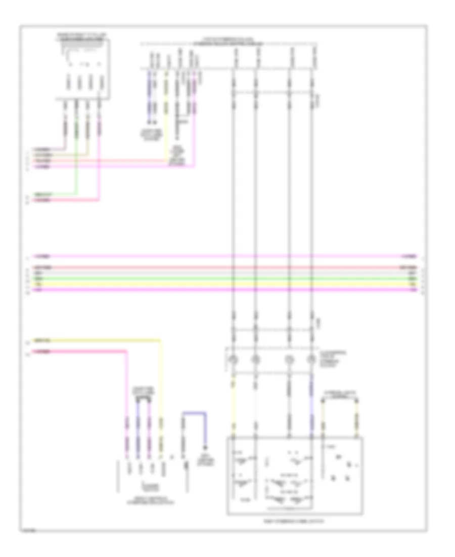
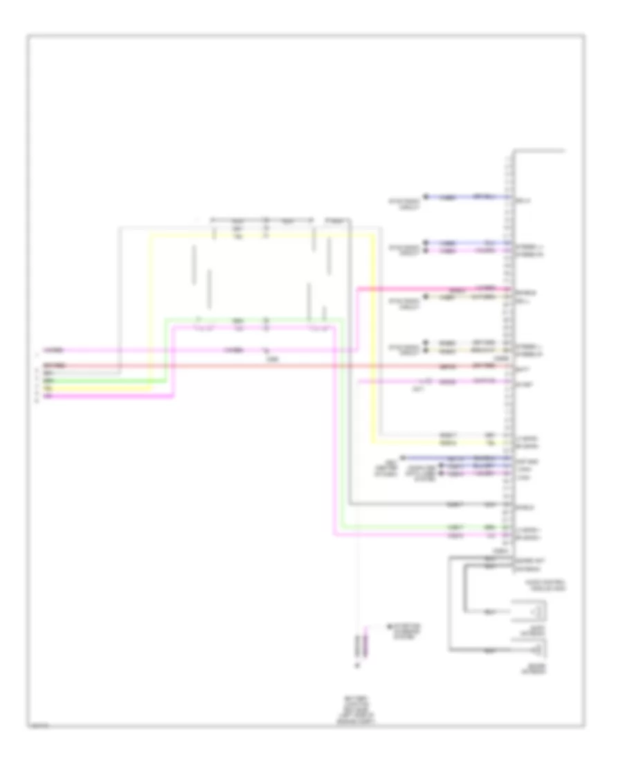
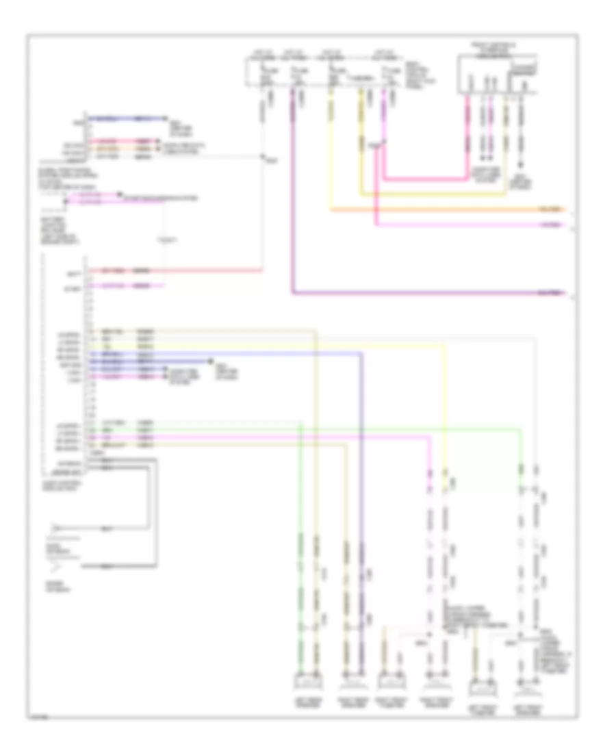
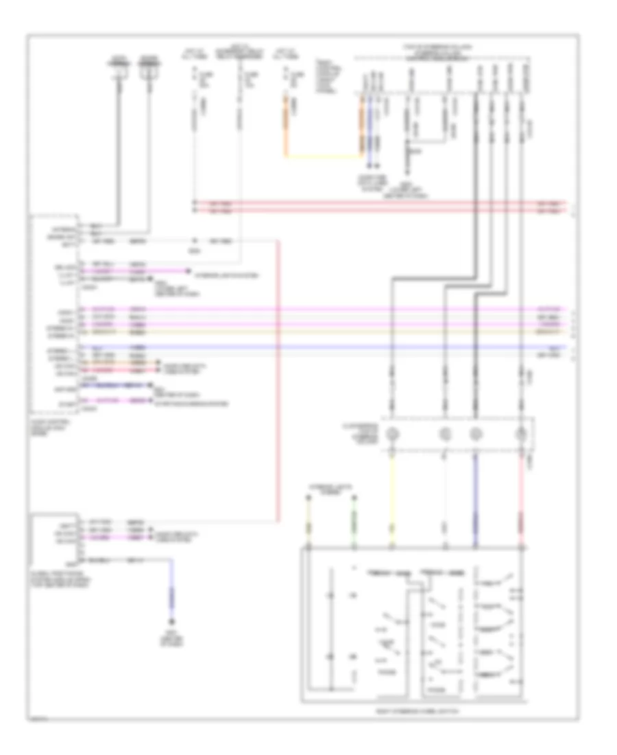
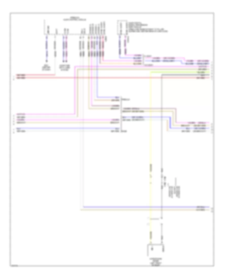
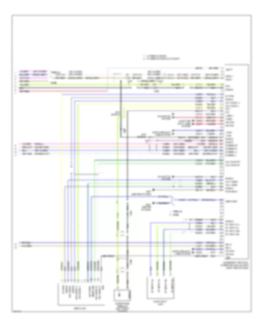
Computer Data Lines Wiring Diagram (1 of 2) for Ford F-250 Super Duty King Ranch 2014
List of elements for Computer Data Lines Wiring Diagram (1 of 2) for Ford F-250 Super Duty King Ranch 2014:
- (body main wiring harness, near breakout to restraints control module)
- (instrument panel wiring harness, in breakout to g203)
- (instrument panel wiring harness, in breakout to inertia fuel shutoff switch) s254
- (instrument panel wiring harness, near breakout to c215) s233
- (instrument panel wiring harness, near breakout to c240c) s224
- (instrument panel wiring harness, near breakout to headlamp switch) (w/ parking aid) s241
- (instrument panel wiring harness, near breakout to headlamp switch) s235
- (instrument panel wiring harness, near breakout to inertia fuel shutoff switch) s211
- (instrument panel wiring harness, near breakout to instrument panel power point 1)
- (lower left center of dash) g203
- (sony w/ 8 inch touch screen) s307
- Accessory protocol interface module (w/ sync) (right end of dash)
- Audio control module (acm) (w/ cd player)
- Audio digital signal processing (dsp) module (sony w/ 8 inch touch screen) (crew cab: base of right "c" pillar) (super cab: center rear of cab floor)
- Automatic a/c
- Body control module (bcm) (right kick panel)
- C207
- C212
- C2280a
- C2280b
- C2280f
- C228a
- C240b
- C2414a
- C290a
- C300
- C312
- C3154a
- C3265c
- C341d
- Circuit deactivation ignition module (cdim) (if equipped) (left end of dash)
- Data link connector (dlc) (bottom left end of dash)
- Driver seat module (dsm) (w/ memory) (under driver's seat)
- Dual climate controlled seat module (dcsm) (w/ climate controlled seats) (under front passenger's seat)
- Front controls interface module (fcim) (premium audio)
- Fuse 15a
- G201 (center of dash)
- Gd115
- Gd184
- Global positioning system module (w/ sync) (top center of dash)
- Heated steering wheel module (hswm) (if equipped) (bottom left end of dash)
- Hot at all times
- Hs can +
- Hs can -
- Hvac module
- I can +
- I can -
- Manual a/c
- Ms can +
- Ms can -
- Parking aid module (pam) (if equipped) (lower left end of dash)
- S210
- S223
- S228
- S234 (instrument panel wiring harness, near breakout to c215)
- S236 (instrument panel wiring harness, near breakout to headlamp switch) c212
- S240 (w/ parking aid)
- S253
- S255
- S256
- S308 (sony w/ 8 inch touch screen) (body main wiring harness, near breakout to restraints control module)
- S380 (body main wiring harness, near breakout to c311)
- S381
- Sbp24
- Sony w/ 8 inch touch screen
- Steering column control module (sccm) (top of steering column)
- Tire pressure monitor module (right end of dash)
- Vdb04
- Vdb05
- Vdb06
- Vdb07
- Vdb13
- Vdb14
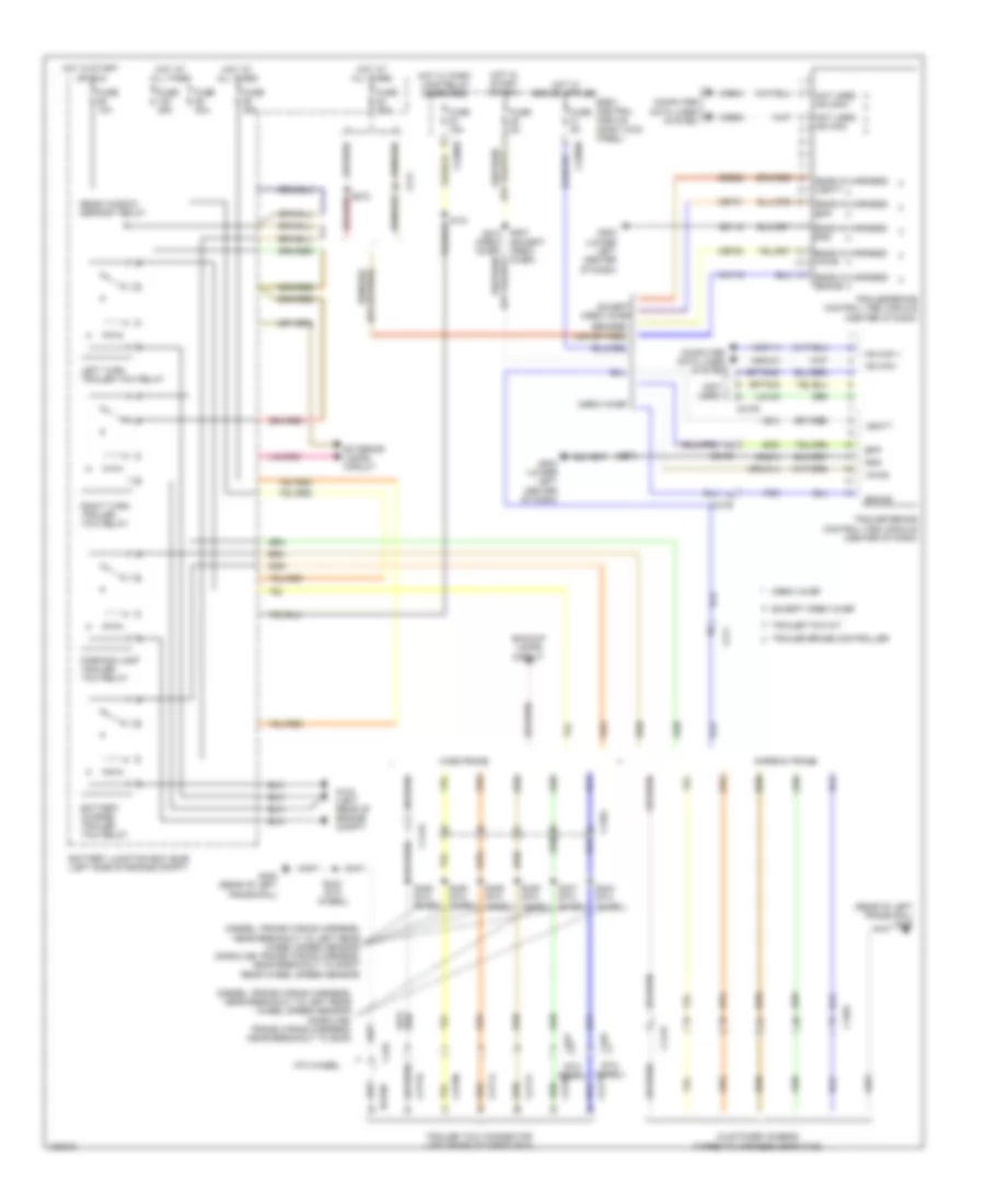
Computer Data Lines Wiring Diagram (2 of 2) for Ford F-250 Super Duty King Ranch 2014
List of elements for Computer Data Lines Wiring Diagram (2 of 2) for Ford F-250 Super Duty King Ranch 2014:
- (body main wiring harness, near breakout to c311) s377
- (instrument panel wiring harness, in breakout to inertia fuel shutoff switch)
- (instrument panel wiring harness, near breakout to c213) (6.7l turbo diesel w/ rapid heat) s218
- (instrument panel wiring harness, near breakout to c213) (6.7l turbo diesel w/ rapid heat) s221
- (t-box jumper wiring harness, near breakout to c2108) (crew chief) s271
- (transmission wiring harness, near breakout to c1010) s187
- (urea jumper wiring harness, near breakout to reductant injector)
- 6.7l turbo diesel
- Anti-lock brake system (abs) module (left side of engine compt)
- Auxiliary heater control module (ahcm) (6.7l turbo diesel w/ rapid heat) (top left front of hvac module)
- C1010
- C1232b
- C1273c
- C1415
- C146
- C175b
- C1i0
- C210
- C2108
- C214
- C2371a
- C2463b
- C263
- C310b
- C3611a
- C3619a
- Can2 +
- Can2 -
- Crew chief
- Except 6.7l turbo diesel
- Glow plug control module (gpcm) (right rear of engine compt)
- Hs can +
- Hs can -
- Hs can yaw +
- Hs can yaw -
- Hsc1-a
- Hsc1-c
- Hsc2-a
- Hsc2-c
- I can +
- I can -
- Instrument panel cluster (ipc)
- Nca
- Nox sensor module 11 (except high sulfur) (near nox sensor 11)
- Nox sensor module 12 (except high sulfur) (near nox sensor 12)
- Powertrain control module (pcm) (right rear of engine compt)
- Restraints control module (rcm) (under center console)
- S102
- S103 (gasoline: engine control sensor engine compt wiring harness, near breakout to c1581) (diesel: engine control sensor engine compt wiring harness, in breakout to c140)
- S106
- S107 (engine control sensor engine compt wiring harness, near breakout to anti-theft hood switch)
- S188 (transmission wiring harness, near breakout to c1010)
- S202 (engine control sensor engine compt wiring harness, near breakout to body control module)
- S212 (w/ sync) (instrument panel wiring harness, near breakout to inertia fuel shutoff switch)
- S213 (w/ sync) (instrument panel wiring harness, near breakout to inertia fuel shutoff switch)
- S229 (instrument panel wiring harness, in breakout to inertia fuel shutoff switch)
- S230
- S270 (crew chief) (t-box jumper wiring harness, near breakout to c2108)
- S378 (body main wiring harness, near breakout to c311)
- S403
- S404
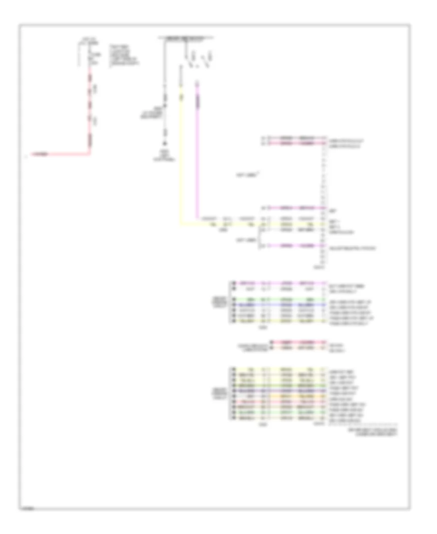
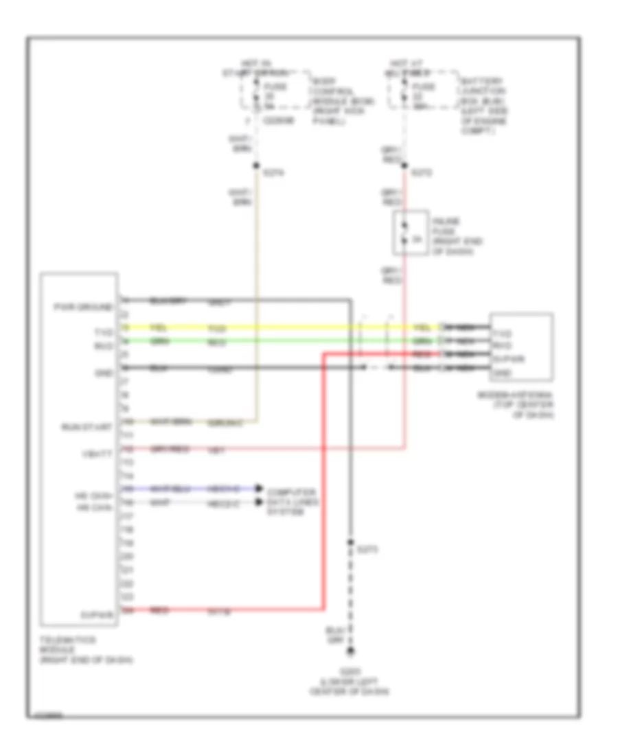
- Telematics module (crew chief) (right end of dash)
- Trailer brake control (tbc) module (center of dash)
- Transfer case control module (tccm) (right end of dash)
- Transmission control module (tcm) (rear of transfer case)
- Vca23
- Vca24
- Vdb04
- Vdb05
- Ve348
- Ve349
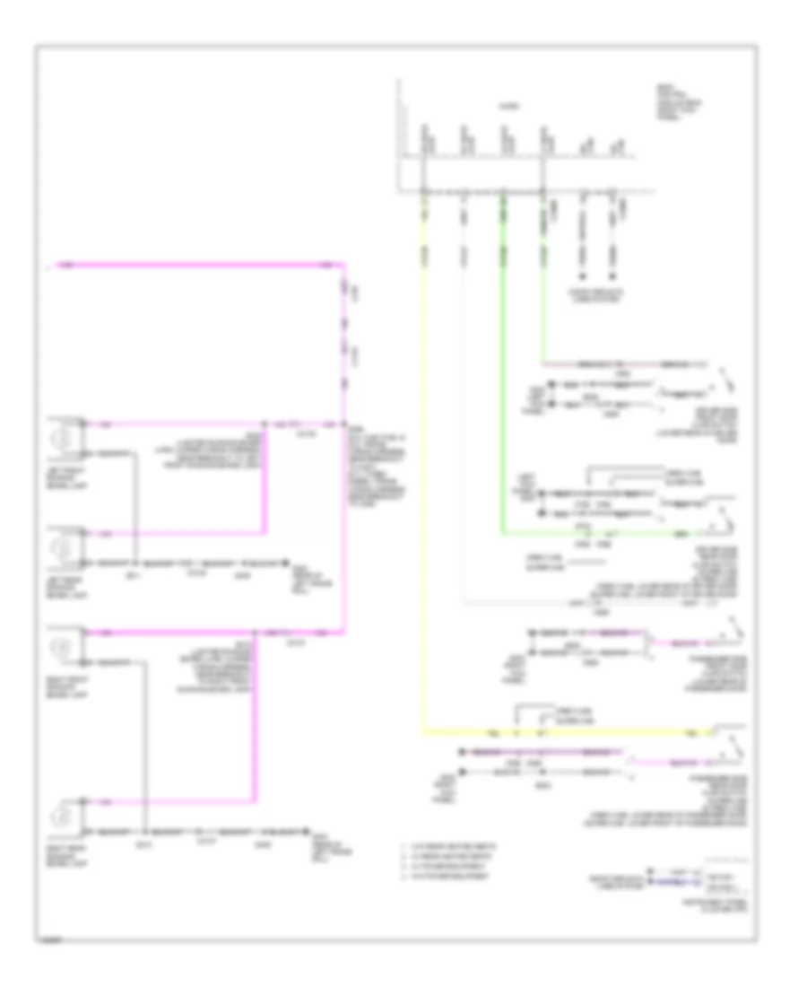
COOLING FAN
Cooling Fan Wiring Diagram for Ford F-250 Super Duty King Ranch 2014
List of elements for Cooling Fan Wiring Diagram for Ford F-250 Super Duty King Ranch 2014:
- (engine control sensor & fuel charge wiring harness, near breakout to c133) (6.2l flex fuel) s116
- (not used)
- 6.2l flex fuel
- 6.7l turbo diesel
- 6.8l
- Battery junction box (left side of engine compt)
- C1047
- C1163
- C1165
- C1220
- C1232b
- C1232e
- C133
- C175b
- C175e
- Cht
- Cooling fan (6.2l flex fuel) (behind radiator)
- Cooling fan (6.7l turbo diesel) (behind radiator)
- Cylinder head temperature sensor (6.2l flex fuel: rear of block, under intake manifold) (6.8l: rear of right cylinder head)
- Ect
- Ect 2
- Engine controls system
- Engine coolant temperature (ect) sensor (top front of engine)
- Except 6.7l turbo diesel
- Fcv
- Fss
- Fuse 10a
- G103 (right rear of engine compt)
- Hot w/ pcm power relay energized
- Le111
- Powertrain control module (right rear of engine compt)
- Pwrgnd
- Re405
- Red
- S101 (6.2l flex fuel)
- S1013 (engine wiring engine harness, near breakout to intake throttle actuator)
- Secondary cooling system engine coolant temperature 2 sensor (top right front of engine)
- Sigrtn
- Vbpwr
- Ve203
- Ve712
- Ve716
- Ve759
- Vec10
- Vpwr
CRUISE CONTROL
6.2L FLEX FUEL
6.2L Flex Fuel, Cruise Control Wiring Diagram for Ford F-250 Super Duty King Ranch 2014
List of elements for 6.2L Flex Fuel, Cruise Control Wiring Diagram for Ford F-250 Super Duty King Ranch 2014:
- (body main wiring harness, in breakout to brake pedal position switch) s207
- (lower left center of dash) g202
- (right rear of engine compt) g103
- (transmission wiring harness, near breakout to c145)
- 6.2l flex fuel
- 6.8l
- Accelerator pedal position sensor (accelerator pedal support)
- App1
- App2
- Apprtn
- Apprtn2
- Appverf2
- Appvref
- Body control module (bcm) (right kick panel)
- Bpp
- Bps
- Brake pedal position switch (top of brake pedal assembly)
- C175b
- C175e
- C175t
- C210
- C218b
- C218c
- C2280b
- C2280d
- C2414a
- C2414d
- Ccb08
- Ce412
- Ce426
- Ces09
- Clockspring (top of steering column)
- Cncl/ rsm
- Computer data lines system
- Electronic throttle control (throttle body assembly)
- Electronic throttle control motor (etc) (throttle body assembly)
- Electronic throttle control position sensor (throttle body assembly)
- Engine controls system
- Etcref
- Etcrtn
- Exterior lights system
- Fuse 10a
- Fuse 5a
- G300 (left kick panel)
- Gd113
- Gd185
- Gnd
- Hot at all times
- Hs can +
- Hs can -
- Hs can+
- Hs can-
- Instrument panel cluster (ipc)
- Interior lights system
- Le111
- Le134
- Le136
- Le137
- Left steering wheel switch
- Logic gnd
- Nca
- On/off
- Oss
- Output shaft speed (oss) sensor (top rear of transmission)
- Powertrain control module (right rear of engine compt)
- Re134
- Re136
- Re137
- Ret04
- Ret24
- S184
- S239
- Sbp26
- Sccrtn
- Sccs
- Set+
- Set-
- Steering column control module (top of steering column)
- Tacm+
- Tacm-
- Tan
- Torqshift 6 transmission
- Tp1
- Tp2
- Tr gnd
- Vbatt
- Vbpwr
- Vdb04
- Vdb05
- Ve701
- Ve702
- Ve818
- Ve819
- W/ 5-button message center
6.7L TURBO DIESEL
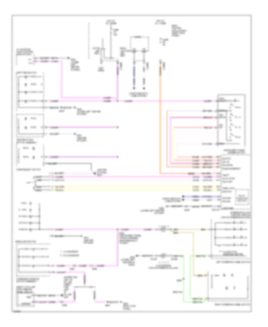
6.7L Turbo Diesel, Cruise Control Wiring Diagram for Ford F-250 Super Duty King Ranch 2014
List of elements for 6.7L Turbo Diesel, Cruise Control Wiring Diagram for Ford F-250 Super Duty King Ranch 2014:
- (engine wiring harness, near breakout to engine coolant temperature sensor) s123
- (engine wiring harness, near breakout to intake throttle actuator)
- (lower left center of dash) g202
- Accelerator pedal position sensor (accelerator pedal support)
- App
- App2
- Apprtn
- Apprtn2
- Appverf2
- Appvref
- Body control module (bcm) (right kick panel)
- Bps bpp
- Brake pedal position switch (top of brake pedal assembly)
- C1232b
- C1232e
- C210
- C218b
- C218c
- C2280b
- C2280d
- C2414a
- C2414d
- Ccb08
- Ce412
- Ce426
- Ces09
- Clockspring (top of steering column)
- Cncl/ rsm
- Computer data lines system
- Exterior lights system
- Fuse 10a
- Fuse 5a
- G103 (right rear of engine compt)
- G300 (left kick panel)
- Gd113
- Gd185
- Gnd
- Hot at all times
- Hs can +
- Hs can -
- Hs can+
- Hs can-
- Instrument panel cluster (ipc)
- Intake throttle actuator (throttle body assembly)
- Interior lights system
- Le111
- Le136
- Le137
- Le423
- Left steering wheel switch
- Logic gnd
- Nca
- On/off
- Oss hall
- Powertrain control module (right rear of engine compt)
- Re136
- Re137
- Re405
- Ret04
- Ret24
- S1013
- S207
- S239
- Sbp26
- Sccrtn
- Sccs
- Set+
- Set-
- Sigrtn
- Steering column control module (top of steering column)
- Tacm+
- Tacm-
- Tan
- Torqshift 6 transmission
- Transmission control module (rear of transfer case)
- Trgnd
- Vbatt
- Vbpwr
- Vdb04
- Vdb05
- Ve701
- Ve702
- Ve820
- Vref
- W/ 5-button message center
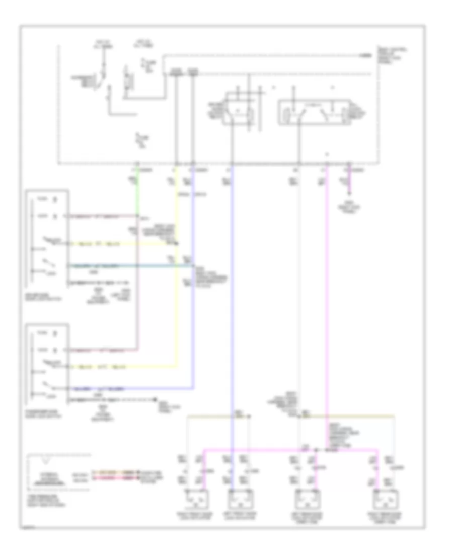
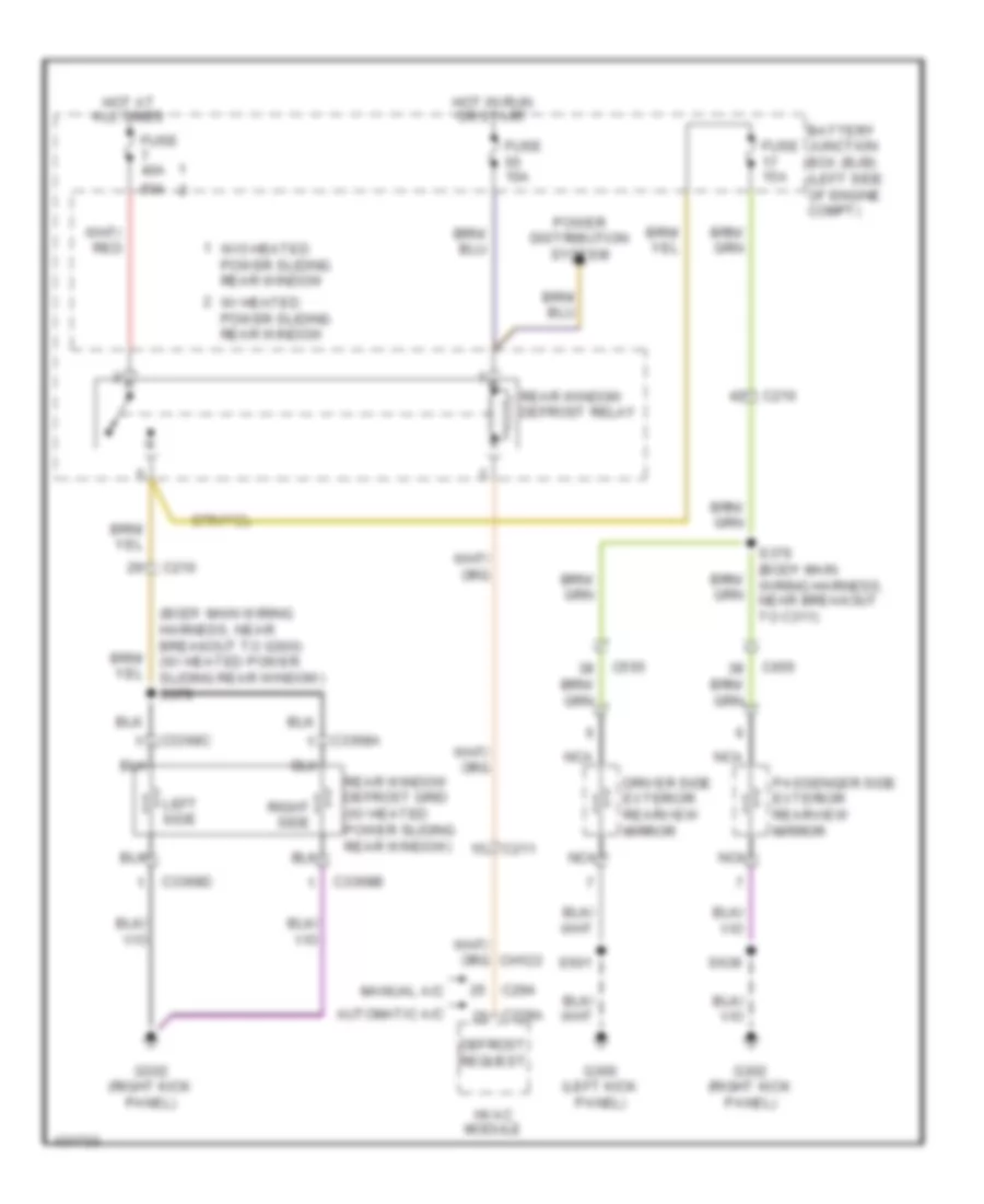
DEFOGGERS
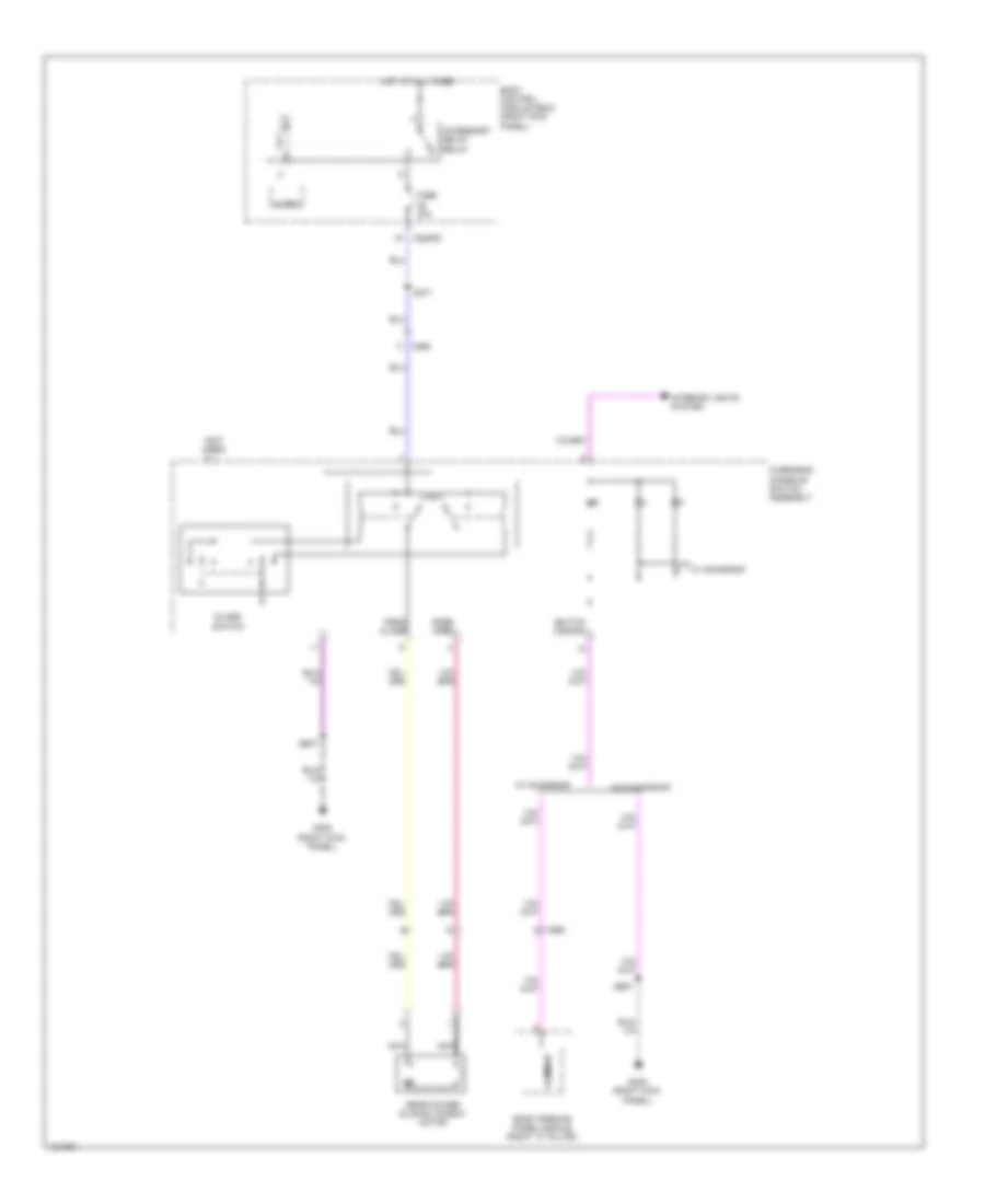
Defoggers Wiring Diagram for Ford F-250 Super Duty King Ranch 2014
List of elements for Defoggers Wiring Diagram for Ford F-250 Super Duty King Ranch 2014:
- (body main wiring harness, near breakout to g300) (w/ heated power sliding rear window) s379
- 50a
- Automatic a/c
- Battery junction box (bjb) (left side of engine compt)
- C210
- C211
- C228a
- C294
- C3368a
- C3368b
- C3368c
- C3368d
- C555
- C655
- Defrost request
- Driver side exterior rearview mirror
- Fuse 10a
- Fuse 15a
- Fuse 40a
- G300 (left kick panel)
- G302 (right kick panel)
- Hot at all times
- Hot in run or start
- Hvac module
- Left side
- Manual a/c
- Nca
- Passenger side exterior rearview mirror
- Power distribution system
- Rear window defrost grid (w/ heated power sliding rear window)
- Rear window defrost relay
- Right side
- S376 (body main wiring harness, near breakout to c311)
- S501
- S639
- W/ heated power sliding rear window
- W/o heated power sliding rear window
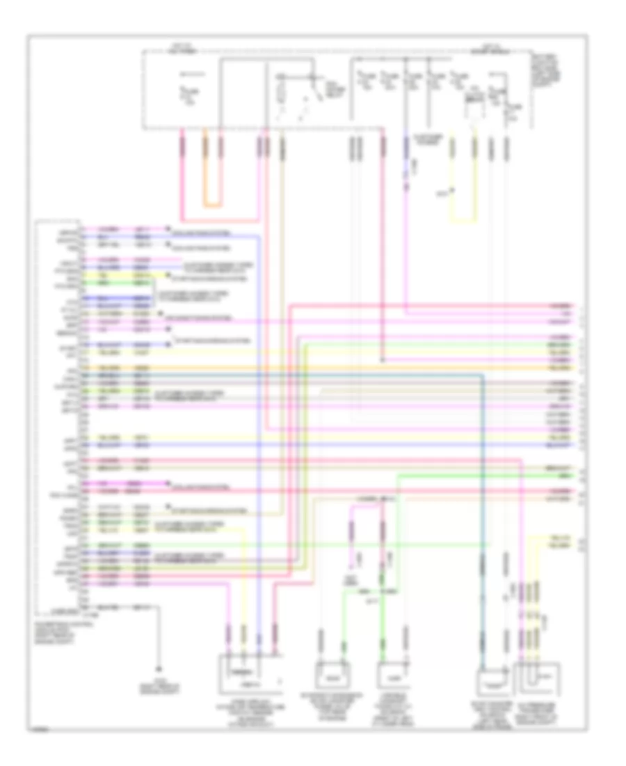
ENGINE PERFORMANCE
6.2L FLEX FUEL
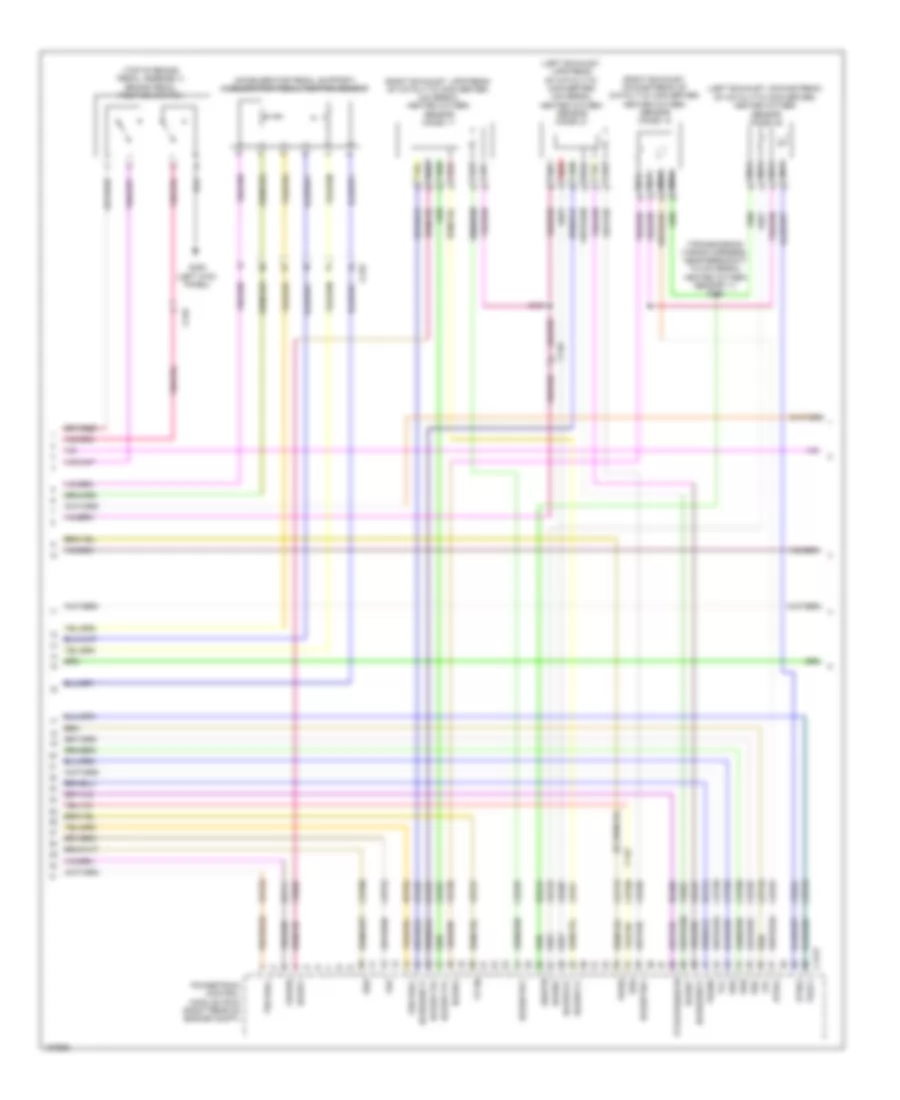
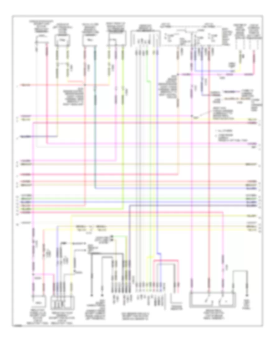
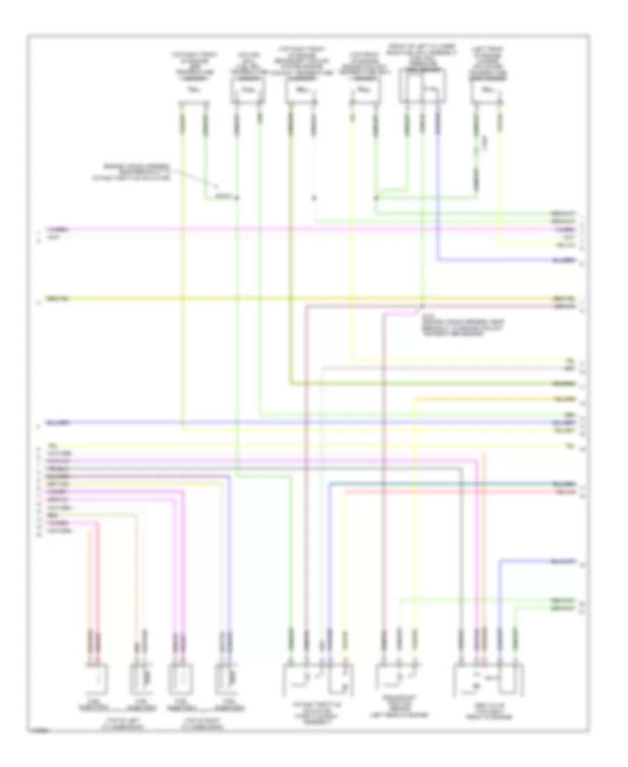
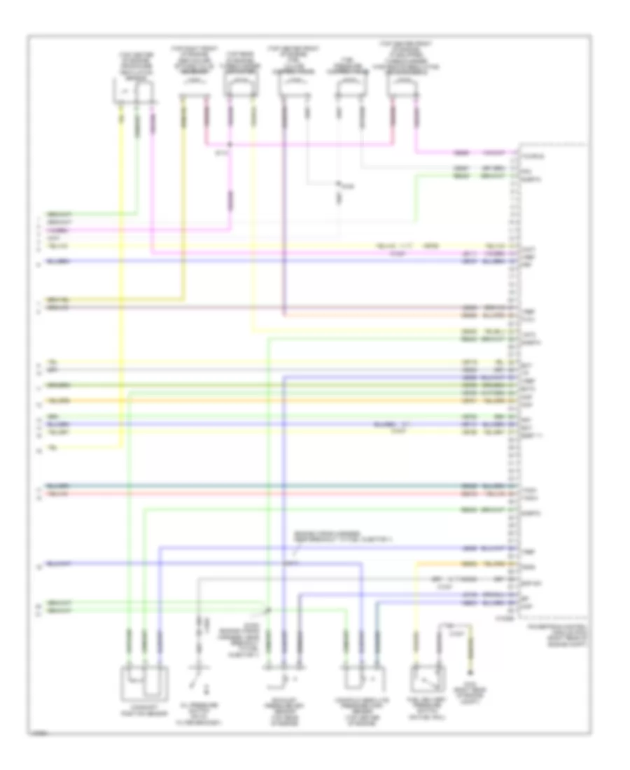
6.2L Flex Fuel, Engine Performance Wiring Diagram (1 of 6) for Ford F-250 Super Duty King Ranch 2014
List of elements for 6.2L Flex Fuel, Engine Performance Wiring Diagram (1 of 6) for Ford F-250 Super Duty King Ranch 2014:
- (customer access taped to harness near c210)
- (customer access)
- (not used)
- 10a
- A/c clutch relay
- A/c pressure transducer (right front of engine compt)
- Aat
- Accr
- Acpt
- Air conditioning system
- App1
- App2
- Apprtn
- Appvref
- Battery junction box (bjb) (left side of engine compt)
- Bpp
- Bps
- C1148
- C1168
- C1581
- C175b
- Canv
- Case gnd
- Cbb52
- Ccb08
- Cdc12
- Cdc15
- Cdc35
- Cdc38
- Ce114
- Ce237
- Ce326
- Ce436
- Ce608
- Ce912
- Ce913
- Ce914
- Ce933
- Ces09
- Cet21
- Cet42
- Cet43
- Ch302
- Cls05
- Cooling fans system
- Cto
- Digital
- Evap canister vent control solenoid (left rear side of frame)
- Evaporative emission (evap) canister purge valve (top rear of engine)
- Fcv
- Fpc
- Fpm
- Fss
- Fuse
- Fuse 10a
- Fuse 15a
- Fuse 20a
- Fuse n/a
- G103 (right rear of engine compt)
- Gd113
- Genmon
- Hot at all times
- Hot in start or run
- Iat
- Injpwrm
- Isp-r
- Le111
- Le136
- Maf
- Mass airflow/ intake air temperature (maf/iat) sensor (on engine intake air duct)
- Pcm power relay
- Pcm wake
- Pcmrc
- Powertrain control module (pcm) (right rear of engine compt)
- Pt oil
- Pto
- Pto eng
- Pto rpm
- Re136
- Re320
- S101
- S104
- S117
- Sig rtn
- Smc
- Smrc
- Sst-d
- Sst-u
- Start
- Starting/charging system
- Tron
- Trop
- Variable camshaft timing (vct 21) solenoid (front of left cylinder head)
- Vbpwr
- Ve203
- Ve225
- Ve518
- Ve701
- Ve702
- Ve740
- Ve807
- Vec10
- Vh407
- Vh433
- Vmc05
- Vref 5v
- Vsout
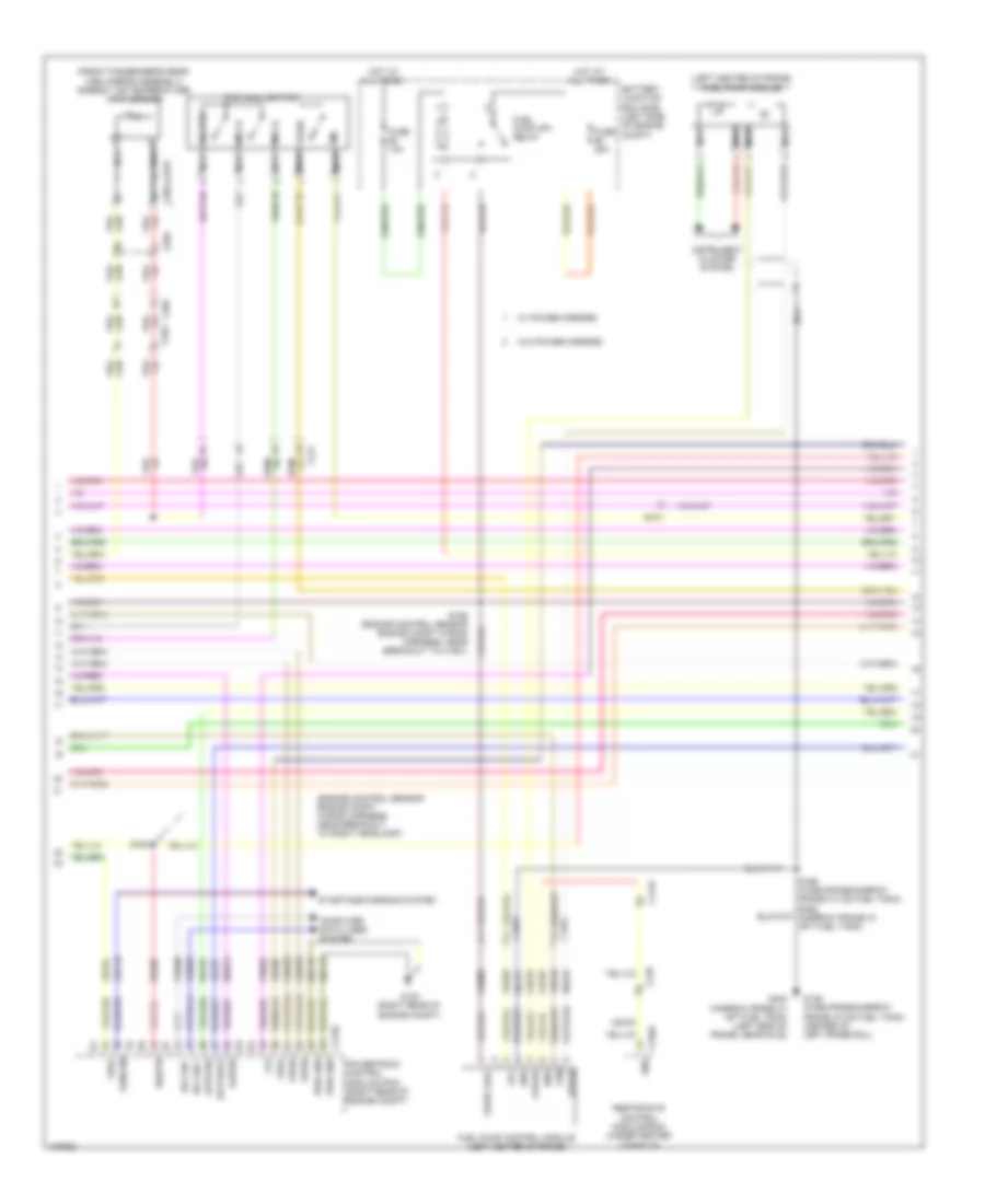
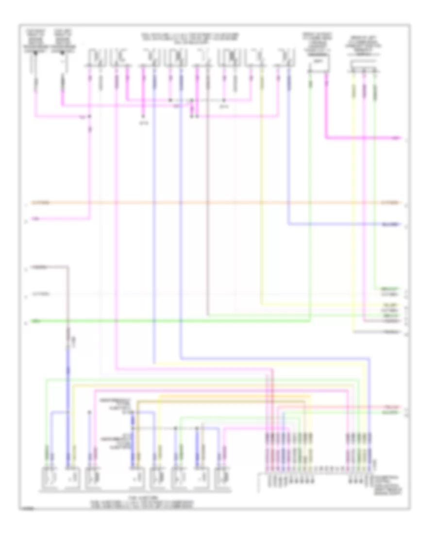
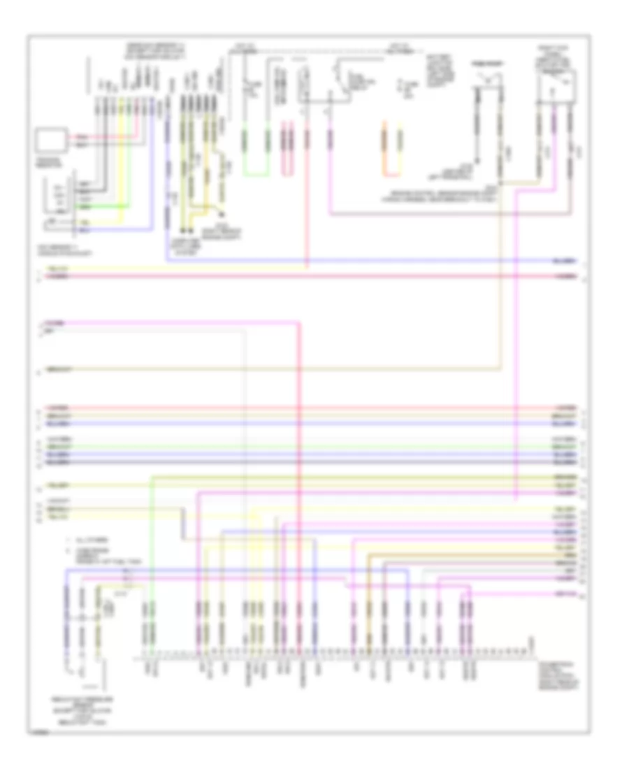
6.2L Flex Fuel, Engine Performance Wiring Diagram (2 of 6) for Ford F-250 Super Duty King Ranch 2014
List of elements for 6.2L Flex Fuel, Engine Performance Wiring Diagram (2 of 6) for Ford F-250 Super Duty King Ranch 2014:
- (engine control sensor engine compt wiring harness, near breakout to right headlamp)
- (front passenger's rear view mirror assembly) ambient air temperature (aat) sensor
- (left center of frame) fuel pump module
- Apprtn2
- Appvref2
- Battery junction box (bjb) (left side of engine compt)
- C1415
- C1581
- C175b
- C210
- C211
- C263
- C265
- C310a
- C601
- C651
- C655
- Cbb33
- Cdc10
- Ce515
- Ce608
- Computer data lines system
- Cr167
- Ens
- Fpc
- Fpm
- Fppwr
- Fprtn
- Ftp
- Fuel pump (fp) relay
- Fuel pump control module (left center of frame)
- Fuse 10a
- Fuse 20a
- G103 (right rear of engine compt)
- G136 (wide frame/narrow frame w/ mid fuel tank) (center of left frame rail)
- G402 (narrow frame w/ aft fuel tank) (left side of frame, near axle)
- Gd113
- Gd177
- Gencom
- Gnd
- Hot at all times
- Hs can +
- Hs can -
- Instrument cluster system
- Kapwr
- Le137
- Le230
- Le424
- Nca
- Powertrain control module (pcm) (right rear of engine compt)
- Pwr gnd
- R/s
- Re137
- Re407
- Re515
- Restraints control module (rcm) (under center console)
- S100
- S156 (engine control sensor engine compt wiring harness, near breakout to c1581)
- S196 (wide frame/narrow frame w/ mid fuel tank) s462 (narrow frame w/ aft fuel tank)
- Sbb72
- Sig rtn
- Sigrtn
- Sst-d
- Sst-u
- Starting/charging system
- Tow haul switch
- Tows
- Vdb04
- Vdb05
- Ve225
- Ve518
- Ve922
- Vpwr
- Vpwr fuel
- Vref
- W/ power mirrors
- W/o power mirrors
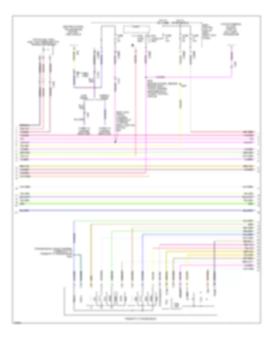
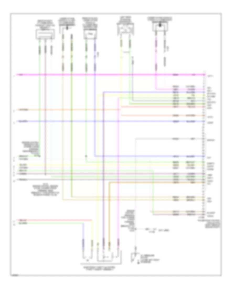
6.2L Flex Fuel, Engine Performance Wiring Diagram (3 of 6) for Ford F-250 Super Duty King Ranch 2014
List of elements for 6.2L Flex Fuel, Engine Performance Wiring Diagram (3 of 6) for Ford F-250 Super Duty King Ranch 2014:
- (body main wiring harness, in breakout to brake pedal position switch) s207
- (center of dash) trailer brake control (tbc) module
- (taped to harness near c422)
- (taped to harness near c465)
- (top of fuel tank) fuel tank pressure (ftp) transducer sensor
- (top of steering column) passive anti-theft transceiver
- (transmission wiring harness, in breakout to torqshift 6 transmission) s182
- Body control module (bcm) (right kick panel)
- Boo
- C1415
- C1581
- C2108
- C212
- C2280b
- C2280d
- C2280f
- C263
- C465
- Crew chief
- Fuel pump (fet)
- Fuse 10a
- Fuse 5a
- Hot at all times
- Hot in start or run
- Lpc
- Micro
- Narrow frame
- Oss
- Pcm wake up (fet)
- S200 (engine control sensor engine compt wiring harness, near breakout to body control module)
- S227
- Ssa
- Ssb
- Ssc
- Ssd
- Sse
- Tcc
- Tftin
- Tftout/sigrtn
- Torqshift 6 transmission
- Trgnd
- Trs/ tr-p
- Tspc1
- Tspc2
- Tss
- Vbpwr
- Wide frame
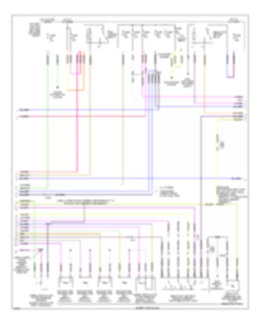
6.2L Flex Fuel, Engine Performance Wiring Diagram (4 of 6) for Ford F-250 Super Duty King Ranch 2014
List of elements for 6.2L Flex Fuel, Engine Performance Wiring Diagram (4 of 6) for Ford F-250 Super Duty King Ranch 2014:
- (accelerator pedal support) accelerator pedal position sensor
- (left exhaust, downstream of catalytic converter) heated oxygen sensor (ho2s) 22
- (left exhaust, upstream of catalytic converter) universal heated oxygen sensor (ho2s) 21
- (right exhaust, downstream of catalytic converter) heated oxygen sensor (ho2s) 12
- (right exhaust, upstream of catalytic converter) universal heated oxygen sensor (ho2s) 11
- (top of brake pedal assembly) brake pedal position switch
- (transmission wiring harness, near breakout to universal heated oxygen sensor 11) s180
- C145
- C175t
- C210
- Cat15
- Ce233
- Ce234
- Ce235
- Ce236
- Cet05
- Cet06
- Cet07
- Cet08
- Cet09
- Cet22
- Cet25
- Cet49
- Cet50
- G300 (left kick panel)
- Ho2s12
- Ho2s22
- Htr12
- Htr22
- Le111
- Le448
- Le449
- Le450
- Le451
- Le452
- Le453
- Lpc
- Nca
- Oss hall
- Powertrain control module (pcm) (right rear of engine compt)
- Re242
- Re406
- Red
- Ret04
- Ret24
- S181
- Sigrtn
- Ssa
- Ssb
- Ssc
- Ssd
- Sse
- Tcc
- Tftin
- Tftout/sigrtn
- Tows
- Trgnd
- Trp
- Tspc1
- Tss hall
- Uo2s11
- Uo2s21
- Uo2sgref11
- Uo2sgref21
- Uo2shtr11
- Uo2shtr21
- Uo2spc11
- Uo2spc21
- Uo2spct11
- Uo2spct21
- Vbpwr
- Ve730
- Ve733
- Ve826
- Ve827
- Vet27
- Vet33
6.2L Flex Fuel, Engine Performance Wiring Diagram (5 of 6) for Ford F-250 Super Duty King Ranch 2014
List of elements for 6.2L Flex Fuel, Engine Performance Wiring Diagram (5 of 6) for Ford F-250 Super Duty King Ranch 2014:
- (coil on plugs 1, 2, 3, & 4: top of right valve cover) (coil on plugs 5, 6, 7 & 8: top of left valve cover) coil on plug (cop)
- (front of right cylinder head) variable camshaft timing (vct 11) solenoid
- (near breakout to fuel injector 3) s119
- (rear of left cylinder bank) camshaft position sensor 21 (cmp 21)
- (top left front of engine) ignition transformer capacitor 2
- (top right front of engine) ignition transformer capacitor 1
- C1168
- C175e
- Ce205
- Ce206
- Ce207
- Ce208
- Ce209
- Ce210
- Ce211
- Ce212
- Ce303
- Ce304
- Ce308
- Ce310
- Ce412
- Ce426
- Cop1a
- Cop2h
- Cop6e
- Cop8d powertrain control module (pcm) (right rear of engine compt)
- Fuel injectors (fuel injectors 1, 2, 3 & 4: top of right cylinder bank) (fuel injectors 5, 6, 7 & 8: top of left cylinder bank)
- Inj-1
- Inj-2
- Inj-3
- Inj-4
- Inj-5
- Inj-6
- Inj-7
- Inj-8
- S113 (near breakout to fuel injector 6)
- S114
- S118
- Tacm +
- Tacm -
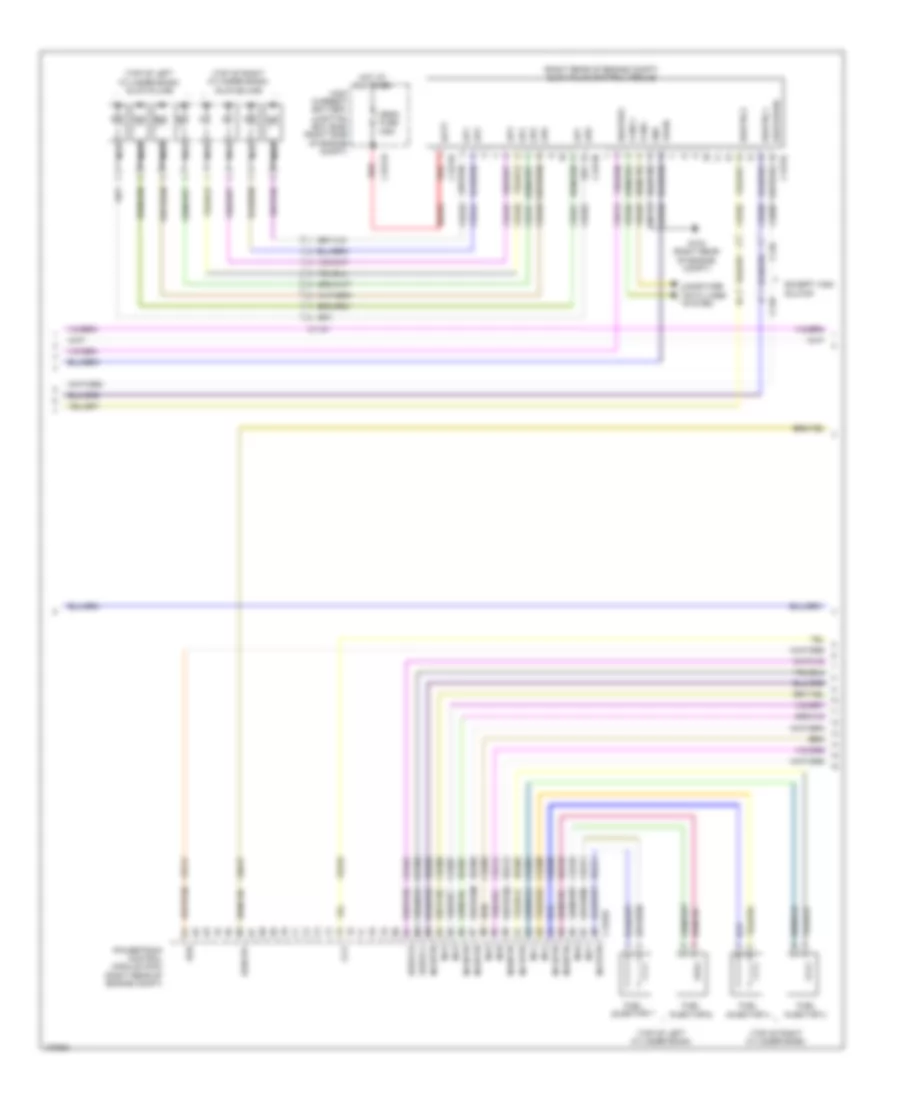
6.2L Flex Fuel, Engine Performance Wiring Diagram (6 of 6) for Ford F-250 Super Duty King Ranch 2014
List of elements for 6.2L Flex Fuel, Engine Performance Wiring Diagram (6 of 6) for Ford F-250 Super Duty King Ranch 2014:
- (engine control sensor & fuel charge wiring harness, near breakout to c1168) s120
- (engine control sensor & fuel charge wiring harness, near breakout to c133) s116
- (left rear of engine) crankshaft position sensor
- (not used)
- (rear of block, under intake manifold) cylinder head temperature (cht) sensor
- (rear of right cylinder bank) camshaft position sensor 11 (cmp 11)
- (under intake manifold, in left cylinder bank) knock sensor 2
- (under intake manifold, in right cylinder bank) knock sensor 1
- C1168
- C133
- C175e
- Ce113
- Ce305
- Ce306
- Ce307
- Ce309
- Ce421
- Ce422
- Cht
- Ckp+
- Ckp-
- Cmc24
- Cmp11
- Cmp21
- Cop3f
- Cop4c
- Cop5b
- Cop7g
- De135
- Electronic throttle control (throttle body assembly)
- Eop-sw
- Etc ref
- Etc rtn
- Evapcp
- Ks1+
- Ks1-
- Ks2+
- Ks2-
- Le111
- Le134
- Oil pressure switch (lower left front of engine)
- Powertrain control module (pcm) (right rear of engine compt)
- Re134
- Re135
- Re323
- Re324
- Re405
- S115 (engine control sensor & fuel charge wiring harness, near breakout to evaporative emission purge valve)
- Shd rtn
- Sigrtn
- Tp1
- Tp2
- Vct11
- Vct21
- Ve711
- Ve712
- Ve736
- Ve738
- Ve801
- Ve802
- Ve818
- Ve819
- Vref
6.7L TURBO DIESEL
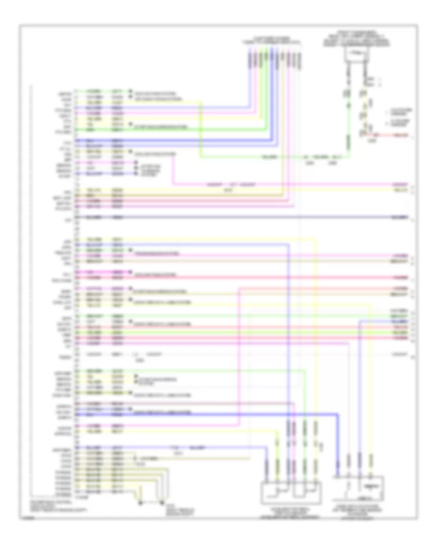
6.7L Turbo Diesel, Engine Performance Wiring Diagram (1 of 7) for Ford F-250 Super Duty King Ranch 2014
List of elements for 6.7L Turbo Diesel, Engine Performance Wiring Diagram (1 of 7) for Ford F-250 Super Duty King Ranch 2014:
- (customer access taped to harness near c210)
- (front passenger's rear view mirror assembly) (except w/ manual aero mirrors) ambient air temperature sensor
- Aat
- Accelerator pedal position sensor (accelerator pedal support)
- Accr
- Acpt
- Air conditioning system
- App
- App2
- Apprtn
- Apprtn2
- Appvref
- Appvref2
- Bcp lamp
- Bcp sw
- Bpp
- Bps
- C1232b
- C210
- C263
- C265
- C601
- C651
- C655
- Can2 high
- Can2 low
- Cbb33
- Cbb52
- Ccb08
- Cdc09
- Cdc12
- Cdc15
- Cdc35
- Cdc38
- Cdc47
- Cdc48
- Ce140
- Ce226
- Ce237
- Ce326
- Ce436
- Ce911
- Ce912
- Ce913
- Ce914
- Ce926
- Ce933
- Ces09
- Cet40
- Ch302
- Computer data lines system
- Cooling fans system
- Cto
- Digital
- Fc-v
- Fdsom
- Fpc
- Fpm
- Fss
- G103 (right rear of engine compt)
- Gd113
- Gencom
- Genmon
- Hs can+
- Hs can-
- Iat
- Isp-r
- Kapwr
- Le111
- Le136
- Le137
- Le424
- Le434
- Maf
- Mass air flow/intake air temperature sensor (on engine intake air duct)
- Nca
- Pcm wake
- Pcmrc
- Powertrain control module (pcm) (right rear of engine compt)
- Pt oil
- Pto
- Pto eng
- Pto ref
- Pto rpm
- Pto rtn
- Pwrgnd
- Re136
- Re137
- Re320
- Re327
- Re407
- S105
- Sbb72
- Sigrtn
- Smc
- Smrc
- Start
- Starting/ charging system
- Starting/charging system
- Transmissions system
- Trsw-pn
- Vbpwr
- Vdb04
- Vdb05
- Ve203
- Ve348
- Ve349
- Ve518
- Ve701
- Ve702
- Ve740
- Ve807
- Ve823
- Vec10
- Vh407
- Vh433
- Vmc05
- Vpwr
- Vref
- Vref 5v
- Vsout
- W/ power mirrors
- W/o power mirrors
- Wif
6.7L Turbo Diesel, Engine Performance Wiring Diagram (2 of 7) for Ford F-250 Super Duty King Ranch 2014
List of elements for 6.7L Turbo Diesel, Engine Performance Wiring Diagram (2 of 7) for Ford F-250 Super Duty King Ranch 2014:
- (body main wiring harness, in breakout to brake pedal position switch)
- (center of dash) trailer brake control module
- (middle of exhaust) (except high sulfur) reductant injector
- (middle of left frame rail) water- in-fuel sensor
- (near nox sensor 12) nox sensor 12
- (on oil filter bracket) engine oil temperature sensor
- (right front of engine compt) a/c pressure transducer
- (taped to harness near c422)
- (top of steering column) passive anti-theft transceiver
- 10a
- All others
- B00
- Body control module (bcm) (right kick panel)
- Brake pedal position switch (top of brake pedal assembly)
- C1046
- C110
- C139 c3047
- C1415
- C1581
- C210
- C2108
- C212
- C2280b
- C2280d
- C2280f
- C263
- C3047 c139
- C3611a
- C3611b
- C465
- Can2 +
- Can2 -
- Cbb36
- Ccb08
- Com
- Computer data lines system
- Crew chief
- Fuse
- G300 (left kick panel)
- G400 (rear of left frame rail)
- G401 (except narrow frame) g403 (narrow frame) (except narrow frame: middle of left frame rail)
- Gd180
- Gnd
- Heater +
- Heater -
- Hot at all times
- Ip1
- Ip2
- Memory +
- Memory -
- Micro
- Narrow frame
- Narrow frame w/ aft fuel tank
- Nca
- Nox sensor module 12 (except high sulfur) (near nox sensor 12)
- Pcm wake up (fet)
- Pnk
- Pwr gnd
- Rdpc
- Reductant pump assembly (except high sulfur) (top of reductant tank)
- Reductant purge valve (except high sulfur) (top of reductant tank)
- S100 (engine control sensor engine compt wiring harness, near breakout to right headlamp)
- S207
- S3000
- S3002
- S405
- Sig gnd
- Trimming resistor
- Ve348
- Ve349
- Vpwr
- Vs +
- Wide frame
- Wide frame/
6.7L Turbo Diesel, Engine Performance Wiring Diagram (3 of 7) for Ford F-250 Super Duty King Ranch 2014
List of elements for 6.7L Turbo Diesel, Engine Performance Wiring Diagram (3 of 7) for Ford F-250 Super Duty King Ranch 2014:
- (near nox sensor 11) (except high sulfur) nox sensor module 11
- (right kick panel) inertia fuel shutoff (ifs) switch
- 20a
- All others
- Battery junction box (bjb) (left side of engine compt)
- C110
- C1232t
- C146
- C1581
- C211
- C3047 c139
- C3619a
- C3619b
- Can2 +
- Can2 -
- Cbb36
- Ce354
- Ce355
- Com
- Computer data lines system
- Dpf
- Dpf12
- Egt 11
- Egt 12
- Egt 13
- Egt 14
- Fuel pump
- Fuel pump (fp) motor diode
- Fuel pump (fp) relay
- Fuse
- Fuse 10a
- G103 (right rear of engine compt)
- G135 (center of left frame rail)
- Gd113
- Heater +
- Heater -
- Hot at all times
- Ip1
- Ip2
- Le425
- Le461
- Memory +
- Memory -
- Nca
- Nox sensor 11 (middle of exhaust)
- Pnk
- Powertrain control module (pcm) (right rear of engine compt)
- Pwr gnd
- Rdinjgnd
- Rdinjpwr
- Rdl1
- Rdl2
- Rdl3
- Rdlrtn
- Rdp
- Rdpc
- Rdpgc
- Rdt
- Re406
- Re839
- Reductant pressure sensor (except high sulfur) (top of reductant tank)
- S124 (engine control sensor engine compt wiring harness, near breakout to c1581)
- Sig gnd
- Sigrtn
- Trimming resistor
- Ve348
- Ve349
- Ve350
- Ve351
- Ve713
- Ve722
- Ve726
- Ve747
- Ve752
- Ve754
- Ve833
- Ve838
- Ve839
- Ve840
- Ve841
- Vpwr
- Vref
- Vs +
- Wide frame/ narrow frame w/ aft fuel tank
6.7L Turbo Diesel, Engine Performance Wiring Diagram (4 of 7) for Ford F-250 Super Duty King Ranch 2014
List of elements for 6.7L Turbo Diesel, Engine Performance Wiring Diagram (4 of 7) for Ford F-250 Super Duty King Ranch 2014:
- (customer access)
- (exhaust aftertreatment pump injector tank wiring harness, near breakout to reductant heater & sensor assembly) s3001
- (urea jumper wiring harness, near breakout to exhaust gas temperature sensor 1)
- (urea jumper wiring harness, near breakout to reductant injector)
- 10a
- A/c clutch relay
- All others
- Battery junction box (bjb) (left side of engine compt)
- C1047
- C110
- C139 c3047
- C1581
- Cooling fans system
- Diesel particulate filter pressure sensor 1 bank 1 (right frame rail)
- Diesel particulate filter pressure sensor 2 (except high sulfur) (right frame rail)
- Except high sulfur
- Exhaust gas temperature (egt) sensor 1 (in exhaust)
- Exhaust gas temperature (egt) sensor 2 (in exhaust)
- Exhaust gas temperature (egt) sensor 3 (in exhaust)
- Exhaust gas temperature (egt) sensor 4 (in exhaust)
- Fuse
- Fuse 10a
- Fuse 15a
- Fuse 25a
- Fuse n/a
- G104 (left rear of engine compt)
- G400 (rear of left frame rail)
- Hot at all times
- Hot in start or run
- Nca
- Pcm power relay
- Power distribution system
- Reductant heater & sensor assembly (top of reductant tank)
- Reductant heater relay
- Reductant pressure line heater assembly (top of reductant tank)
- S108
- S122
- S3002
- S405
- S408
- Wide frame/ narrow frame w/ aft fuel tank
6.7L Turbo Diesel, Engine Performance Wiring Diagram (5 of 7) for Ford F-250 Super Duty King Ranch 2014
List of elements for 6.7L Turbo Diesel, Engine Performance Wiring Diagram (5 of 7) for Ford F-250 Super Duty King Ranch 2014:
- (right rear of engine compt) glow plug control module
- (top of left cylinder bank)
- (top of left cylinder bank) glow plugs
- (top of right cylinder bank)
- (top of right cylinder bank) glow plugs
- 125a
- Batt
- C110
- C1147
- C1232e
- C1273a
- C1273b
- C1273c
- C146
- C1617b
- Can2 +
- Can2 -
- Cbb36
- Ccv
- Ce101
- Ce102
- Ce205
- Ce206
- Ce207
- Ce208
- Ce209
- Ce210
- Ce211
- Ce212
- Ce243
- Ce244
- Ce245
- Ce246
- Ce247
- Ce248
- Ce251
- Ce252
- Ce352
- Ce356
- Ce513
- Ce609
- Computer data lines system
- Egr
- Egrcbv
- Egrvch
- Egrvcl
- Except high sulfur
- Fuel injector 1
- Fuel injector 4
- Fuel injector 6
- Fuel injector 7
- G103 (right rear of engine compt)
- Gd113
- Gnd
- Gp1
- Gp2
- Gp3
- Gp4
- Gp5
- Gp6
- Gp7
- Gp8
- High current battery junction box (bjb) (right side of engine compt)
- Hot at all times
- Inj1
- Inj1rtn
- Inj2
- Inj2rtn
- Inj3
- Inj3rtn
- Inj4
- Inj4rtn
- Inj5
- Inj5rtn
- Inj6
- Inj6rtn
- Inj7
- Inj7rtn
- Inj8
- Inj8rtn
- Mega fuse
- Nca
- Powertrain control module (pcm) (right rear of engine compt)
- Rdhtrc1
- Rdhtrc2
- Rdhtrpc
- Rdhtrpwr
- Re205
- Re206
- Re207
- Re208
- Re209
- Re210
- Re211
- Re212
- Red
- Sbf04
- Ve348
- Ve349
- Ve721
- Ve763
- Ve917
- Vpwr
6.7L Turbo Diesel, Engine Performance Wiring Diagram (6 of 7) for Ford F-250 Super Duty King Ranch 2014
List of elements for 6.7L Turbo Diesel, Engine Performance Wiring Diagram (6 of 7) for Ford F-250 Super Duty King Ranch 2014:
- (engine wiring harness, near breakout to intake throttle actuator)
- (front of left cylinder bank fuel rail assembly) fuel rail pressure (frp) sensor
- (left front of engine) charge air cooler temperature (cact) sensor
- (on fuel rail) fuel rail temperature sensor
- (top front of engine) engine coolant temperature (ect) sensor
- (top of left cylinder bank)
- (top of right cylinder bank)
- (top right front of engine) egr temperature sensor
- (top right front of engine) secondary cooling system engine coolant temperature 2 sensor
- C1047
- Crankshaft position sensor (left rear of engine)
- Egr valve (top right front of engine)
- Fuel injector 2
- Fuel injector 3
- Fuel injector 5
- Fuel injector 8
- Intake throttle actuator (throttle body assembly)
- S1013
- S123 (engine wiring harness, near breakout to engine coolant temperature sensor)
6.7L Turbo Diesel, Engine Performance Wiring Diagram (7 of 7) for Ford F-250 Super Duty King Ranch 2014
List of elements for 6.7L Turbo Diesel, Engine Performance Wiring Diagram (7 of 7) for Ford F-250 Super Duty King Ranch 2014:
- (engine wiring harness, near breakout to fuel injector 1)
- (top center front of engine) (if equipped) turbocharger wastegate regulating valve solenoid
- (top center front of engine) fuel volume control valve
- (top center of engine) crankcase ventilation sensor
- (top rear of engine) turbocharger actuator
- (top right front of engine) egr cooler bypass valve solenoid
- C1046
- C1047
- C1232e
- Cact
- Camshaft position sensor
- Ce256
- Ce257
- Ce412
- Ce426
- Ce435
- Ce460
- Ce932
- Ckp
- Cmc24
- Cmp
- Ect
- Ect2
- Egrt 11
- Eop sw
- Eot
- Exhaust pressure (ep) sensor (top rear of engine)
- Fdps
- Fpc
- Frp
- Frt
- Fuel delivery pressure switch (on fuel rail)
- Fuel pressure control valve
- Fvcv
- G103 (right rear of engine compt)
- Le111
- Le152
- Le423
- Le458
- Manifold absolute pressure (map) sensor (top center of engine)
- Map
- Oil pressure switch (on oil filter bracket)
- Powertrain control module (pcm) (right rear of engine compt)
- Re405
- S1002 (engine wiring harness, near breakout to fuel injector 1)
- S109
- S110
- S111
- Sigrtn
- Tacm+
- Tacm-
- Tcwrvs
- Ve701
- Ve716
- Ve718
- Ve726
- Ve727
- Ve728
- Ve736
- Ve755
- Ve759
- Ve803
- Ve820
- Vgtc
- Vref
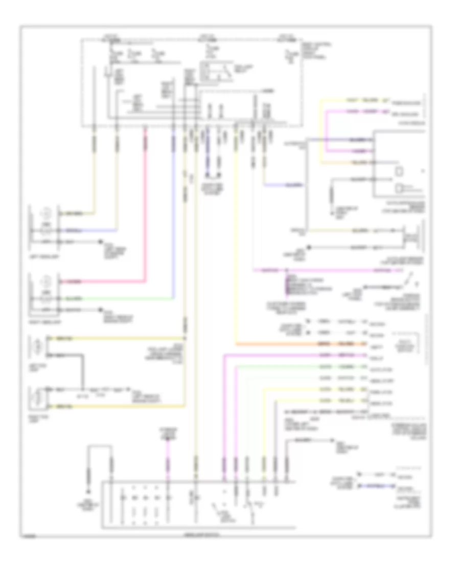
EXTERIOR LIGHTS
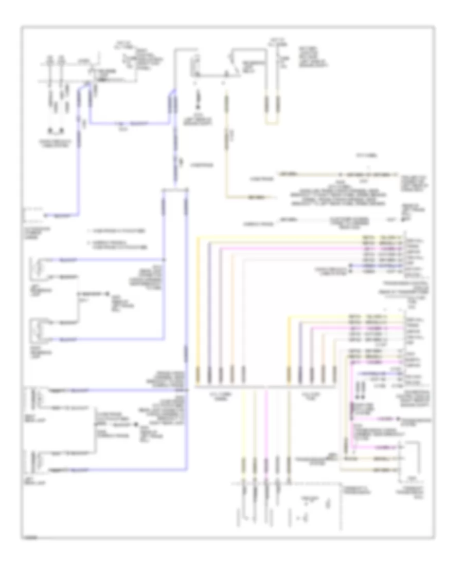
Backup Lamps Wiring Diagram for Ford F-250 Super Duty King Ranch 2014
List of elements for Backup Lamps Wiring Diagram for Ford F-250 Super Duty King Ranch 2014:
- (customer access) (taped to harness near c422)
- (frame wiring harness, near breakout to g400) (narrow frame) s440
- (rear of left frame rail) g400
- (wide frame w/o pickup bed) s400
- 5th wheel
- 6.2l flex fuel
- 6.7l turbo
- 6.8l
- Auto-dimming interior mirror
- Battery junction box (bjb) (left side of engine compt)
- Body control module (bcm) (right kick panel)
- C1415
- C175b
- C175t
- C210
- C2280d
- C2280f
- C264
- C431
- C465
- Cet22
- Computer data lines system
- Diesel
- Fuse 10a
- Fuse 15a
- G104 (left rear of engine compt)
- G400 (rear of left frame rail)
- Hot at all times
- Hs can +
- Hs can -
- Hs can+
- Hs can-
- Le111
- Left rear lamp
- Left reversing lamp
- Micro
- Narrow frame
- Narrow frame & wide frame w/o pickup bed
- Nca
- Oss
- Oss hall
- Powertrain control module (right rear of engine compt)
- Ret04
- Ret24
- Reverse lamp (fet)
- Reversing
- Reversing lamp relay
- Right rear lamp
- Right reversing lamp
- S184 (transmission wiring harness, near breakout to c145)
- S185
- S402 (wide frame w/o pickup bed) (rear lamp connector wiring harness, in breakout to right rear lamp)
- S405 (narrow frame)
- S411
- S414 (rear lamp connector wiring harness near breakout to c465)
- S446 (5th wheel) (gasoline: frame wiring harness, near breakout to right rear wheel speed sensor) (diesel: frame wiring harness, near breakout to left rear wheel speed sensor)
- Sigrtn
- Torqshift 6 transmission
- Torqshift transmission (6.8l)
- Tr-p
- Trailer tow connector (left rear of cargo box)
- Transmission control module (rear of transfer case)
- Transmissions system
- Trgnd
- Trp
- Trs/tr-p
- Tss
- Tss hall
- Vbpwr
- Vdb04
- Vdb05
- Vet33
- Wide frame
- Wide frame w/ pickup bed
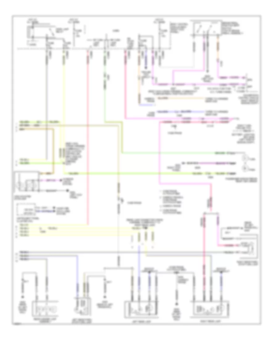
Exterior Lamps Wiring Diagram (1 of 2) for Ford F-250 Super Duty King Ranch 2014
List of elements for Exterior Lamps Wiring Diagram (1 of 2) for Ford F-250 Super Duty King Ranch 2014:
- (air curtain & roof markers wiring harness, near breakout to left center roof marker lamp) s906
- (bumper rear park aid wiring harness, near breakout to left license plate lamp)
- (left kick panel) g300
- (lower left center of dash) g202
- (not used)
- (rear lamp connector wiring c4000 harness, near breakout to right rear side lamp 2) s424
- (rear lamp connector wiring harness, near breakout to rear marker lamp assembly) s412
- (rear lamp connector wiring harness, near c4002 breakout to left rear side lamp 2) s423
- 8-inch touch screen
- Auto
- Auto lp on
- Battery junction box (bjb) (left side of engine compt)
- Body control module (right kick panel)
- C1415
- C210
- C2280a
- C2280b
- C2280c
- C2280d
- C2280f
- C2402
- C2414a
- C2414b
- C408
- C465
- C555
- C913
- Center roof marker lamp
- Clf19
- Clf23
- Clf24
- Clf34
- Cls32
- Computer data lines system
- Driver side exterior rear view mirror
- Except 8-inch touch screen
- Fuse 15a
- Fuse 5a
- G104 (left rear of engine compt)
- G108 (right rear of engine compt)
- G201 (center of dash)
- G400 (rear of left frame rail)
- Gd184
- Gd185
- Gnd
- Hazard
- Hazard switch
- Head
- Head lp off
- Head lp on
- Headlamp switch
- Hot at all times
- Hs can +
- Hs can -
- I can +
- I can -
- Left center roof marker lamp
- Left front park/turn lamp
- Left license plate lamp
- Left rear side lamp 1
- Left rear side lamp 2
- Left roof marker lamp
- Left side marker lamp
- Left turn trailer tow relay
- Lf turn lamp (fet)
- Logic gnd
- Lr stop/turn lamp (fet)
- Lr turn lamp (fet)
- Micro
- Multi-fuction switch
- Nca
- Off
- Park
- Park lp on
- Parking lamp trailer tow relay
- Pwr gnd
- Right center roof marker lamp
- Right front park/turn lamp
- Right license plate lamp
- Right rear side lamp 1
- Right rear side lamp 2
- Right roof marker lamp
- Right side marker lamp
- S121 (engine control sensor engine compt wiring harness, near breakout to anti-theft hood switch)
- S228
- S239
- S418
- S425
- S426
- S436
- S441 (except gasoline: frame wiring harness, near breakout to g400) (gasoline: frame wiring harness, near breakout to c465)
- S501
- S905
- Sbp24
- Sbp26
- Steering column control module (except 8-inch touch screen) front controls interface module (fcim) (8-inch touch screen) (except 8-inch touch screen: top of steering column)
- Stop/ chmsl (fet)
- Turn
- Vbatt
- Vdb04
- Vdb04 (or vdb13)
- Vdb05
- Vdb05 (or vdb14)
- W/ dual rear wheels
- Wide frame w/ pickup bed
- Wide frame w/o pickup bed
Exterior Lamps Wiring Diagram (2 of 2) for Ford F-250 Super Duty King Ranch 2014
List of elements for Exterior Lamps Wiring Diagram (2 of 2) for Ford F-250 Super Duty King Ranch 2014:
- (body main wiring harness, in breakout to dual climate controlled seat module) (w/ power mirrors) s374
- (rear lamp connector wiring harness, in breakout to right rear lamp) s422
- (rear of left frame rail) g400
- (wide frame w/o pickup bed) s400
- 6.7l turbo diesel
- 6.8l & 6.2l flex fuel
- Backup lamps circuit
- Battery junction box (bjb) (left side of engine compt)
- Body control module (bcm) (right kick panel)
- Bpp
- Bps
- Brake pedal position (bpp) switch (top of brake pedal assembly)
- C1232b
- C1415
- C175b
- C210
- C212
- C2280b
- C2280c
- C2280d
- C2280e
- C2280f
- C465
- C555
- C655
- Ccb08
- Ces09
- Computer data lines system
- Fuse 10a
- Fuse 15a
- Fuse 5a
- G300 (left kick panel)
- G302 (right kick panel)
- G400 (rear of left frame rail)
- High mounted stoplamp
- Hot at all times
- Hs can +
- Hs can -
- Instrument panel cluster (ipc)
- Interior lights system
- Left rear lamp
- Left rear park/ stop/turn lamp
- Micro
- Narrow frame
- Narrow frame &
- Nca
- Park
- Park lamp relay
- Passenger side exterior rear view mirror
- Powertrain control module (right rear of engine compt)
- Rear marker lamp assembly
- Reversing
- Rf turn lamp (fet)
- Right rear lamp
- Right rear park/ stop/turn lamp
- Right turn trailer tow relay
- Rr stop/ turn lamp (fet)
- Rr turn lamp (fet)
- S207 (body main wiring harness, in breakout to brake pedal position switch)
- S405 (narrow frame)
- S411
- S639
- Stop/ turn
- Stop/turn
- Taped to harness near c422
- Taped to harness near c465
- Trailer tow circuit
- Turn
- W/o pickup bed
- Wide frame
- Wide frame w/ pickup bed
- Wide frame w/o pickup bed
Trailer Tow Wiring Diagram for Ford F-250 Super Duty King Ranch 2014
List of elements for Trailer Tow Wiring Diagram for Ford F-250 Super Duty King Ranch 2014:
- (5th wheel)
- (customer access) (taped to harness near c422)
- (diesel: frame wiring harness, near breakout to left rear wheel speed sensor) (gasoline: frame wiring harness, near breakout to g400)
- (diesel: frame wiring harness, near breakout to left rear wheel speed sensor) (gasoline: frame wiring harness, near breakout to right rear wheel speed sensor)
- (except crew chief)
- (not used)
- (rear of left frame rail) g400
- 5th wheel
- Backup lamps circuit
- Battery charge trailer tow relay
- Battery junction box (bjb) (left side of engine compt)
- Body control module (right kick panel)
- Boo
- Bpp
- Bptgnd
- Bptsig
- Brake
- C1415
- C1581
- C2108
- C211
- C2280b
- C2280e
- C431
- C432
- Cat06
- Cat09
- Cat14
- Cat16
- Cat17
- Cat19
- Cbp31
- Cbp35
- Computer data lines system
- Crew chief
- Ends in harness bpp
- Ends in harness brake
- Ends in harness gnd
- Ends in harness vbatt
- Ends in harness vpwr
- Except crew chief
- Exterior lamps circuit
- Fuse 10a
- Fuse 15a
- Fuse 25a
- Fuse 30a
- Fuse 5a
- G104 (left rear of engine compt)
- G203 (lower left center of dash)
- G400 (rear of left frame rail)
- Gd115
- Gnd
- Gnd-a
- Hot at all times
- Hot in start or run
- Hot w/ park lamp relay energized
- Hs can +
- Hs can -
- Hsc1-a
- Hsc2-a
- Igrun-a
- Lca16
- Left turn trailer tow relay
- Narrow frame
- Not used hs can+
- Not used hs can-
- Parking lamp trailer tow relay
- Rat08
- Rear window defrost relay
- Right turn trailer tow relay
- S121
- S272
- S273
- S443 (5th wheel)
- S444 (5th wheel)
- S445 (5th wheel)
- S446 (5th wheel)
- S447 (5th wheel)
- S448 (5th wheel)
- S449 (5th wheel)
- Sbb22
- Tbo
- Trailer brake control (tbc) module (center of dash)
- Trailer brake controller
- Trailer tow connector (left rear of cargo box)
- Trailer tow kit
- Vb-a
- Vbatt
- Vdb04
- Vdb05
- Vpwr
- Wide frame
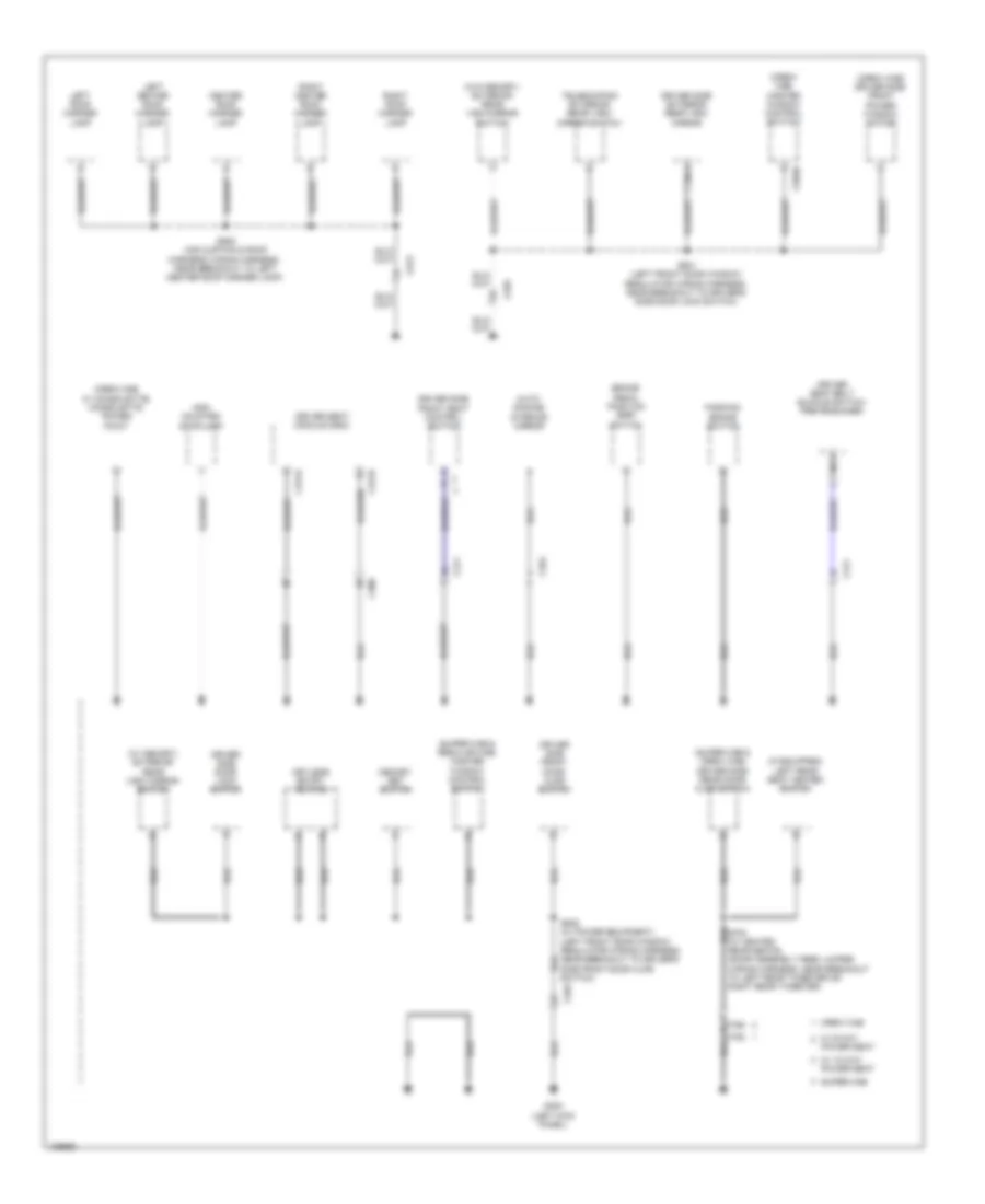
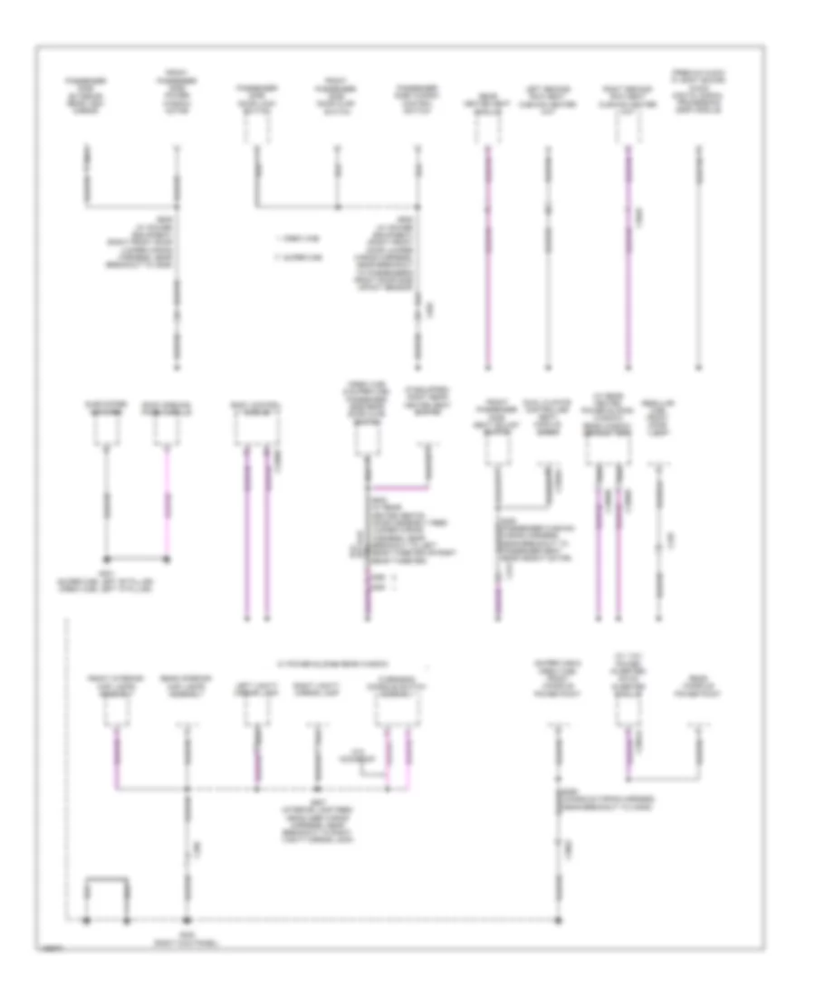
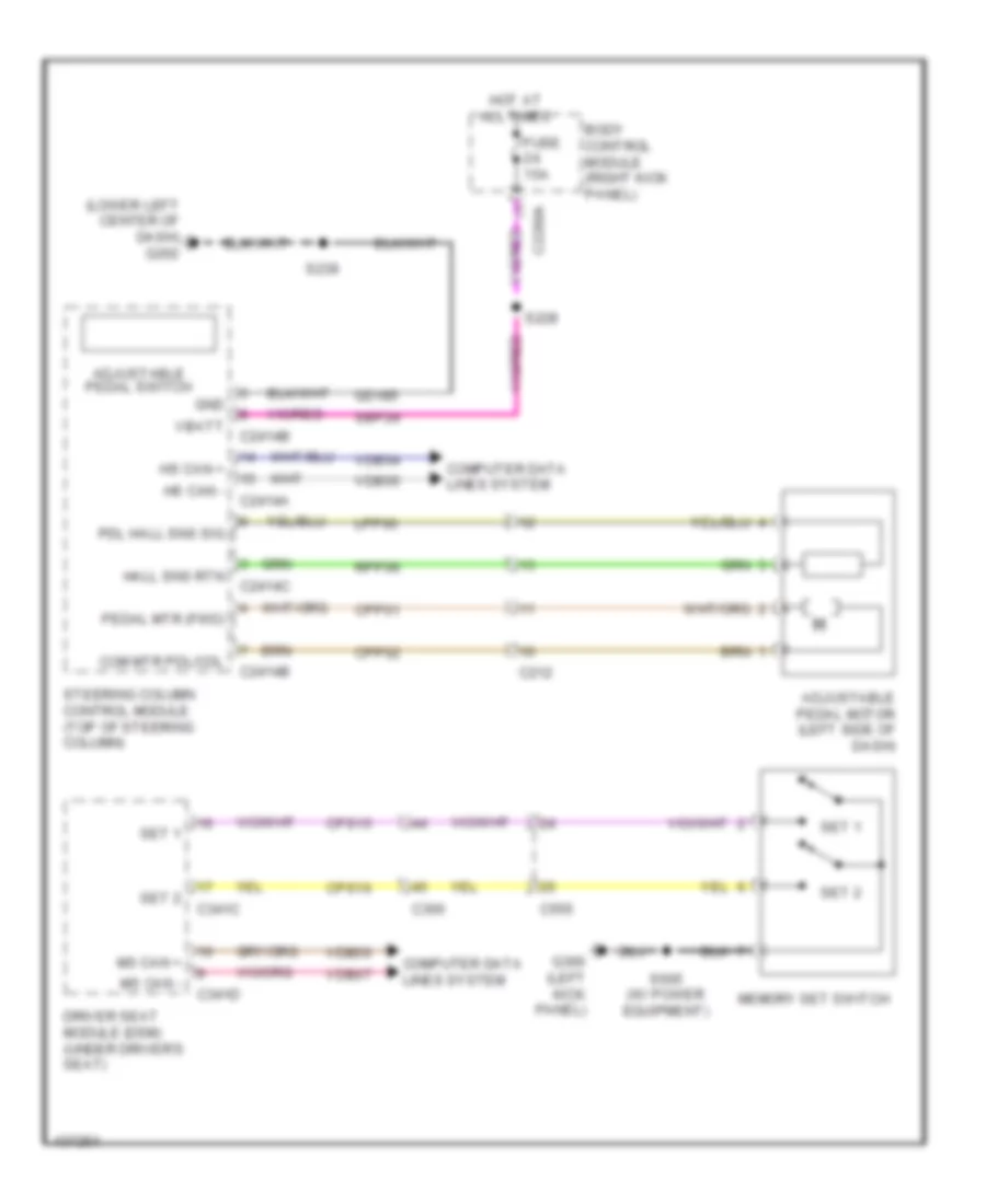
GROUND DISTRIBUTION
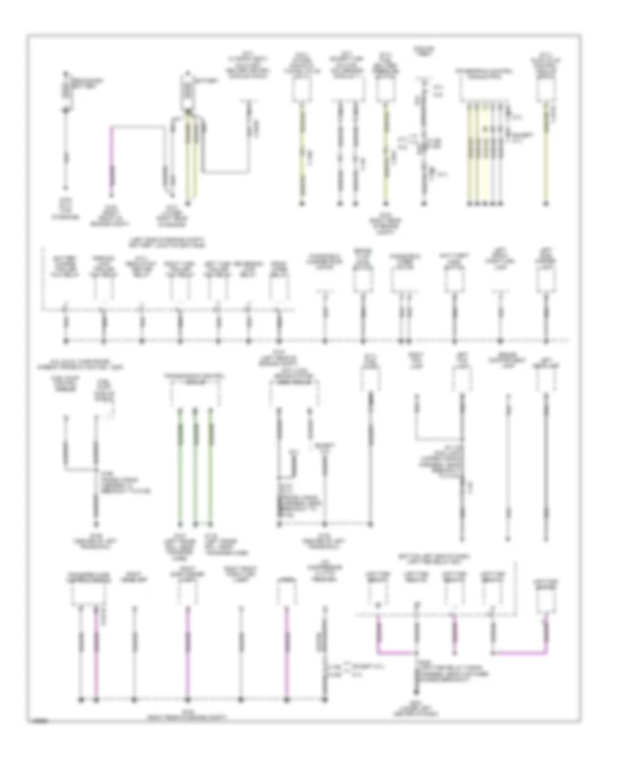
Ground Distribution Wiring Diagram (1 of 5) for Ford F-250 Super Duty King Ranch 2014
List of elements for Ground Distribution Wiring Diagram (1 of 5) for Ford F-250 Super Duty King Ranch 2014:
- (6.7l except high sulfur) nox sensor module 11
- (6.7l w/ rapid heat) auxiliary heater control module (ahcm)
- (6.7l) fuel delivery pressure switch
- (6.7l) fuel pump
- (6.7l) glow plug control module (gpcm)
- (6.7l) reductant heater relay
- (6.8l) intake manifold tuning valve (imtv)
- (bottom left end of dash) upfitter relay box
- (left side of engine compt) battery junction box (bjb)
- 6.2l
- 6.2l & 6.8l wide frame/ narrow frame w/ mid fuel tank
- 6.7l
- A/c compressor clutch field coil
- Anti-lock brake system (abs) module
- Anti-theft hood switch
- Battery
- Battery charge trailer tow relay
- Brake fluid level switch
- C1046
- C1047
- C1168
- C1232b
- C1273c
- C134
- C146
- C175b
- C2371b
- C2463a
- Cooling fan
- Engine compartment lamp
- Except 6.7l
- Front wiper relay
- Fuel pump control module
- Fuel pump module shield
- G100 (right front of engine compt)
- G101 (lower right rear of engine)
- G102 (6.7l) (top of engine)
- G103 (right rear of engine compt)
- G104 (left rear of engine compt)
- G107 (left frame rail, near transfer case)
- G108 (right rear of engine compt)
- G116 (left frame rail, near transfer case)
- G135 (center of left frame rail)
- G136 (center of left frame rail)
- G204 (lower left center of dash)
- Horn
- Left fog lamp
- Left front park/turn lamp
- Left headlamp
- Left side marker lamp
- Left turn trailer tow relay
- Nca
- Parking lamp trailer tow relay
- Powertrain control module (pcm)
- Reversing lamp relay
- Right fog lamp
- Right front park/turn lamp
- Right headlamp
- Right side marker lamp
- Right turn trailer tow relay
- S170 (6.7l) (frame wiring harness, near breakout to g135)
- S196 (frame wiring harness, in breakout to g136)
- S249 (upfitter relay wiring harness, near customer access breakout)
- Secondary battery
- Transfer case control module
- Transmission control module
- Upfitter relay 1
- Upfitter relay 2
- Upfitter relay 3
- Upfitter relay 4
- Upfitter switch
- Windshield washer pump motor
- Windshield wiper motor
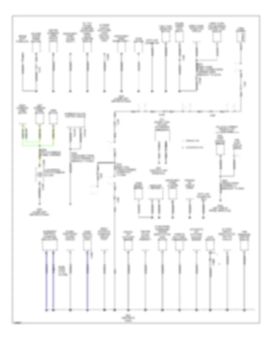
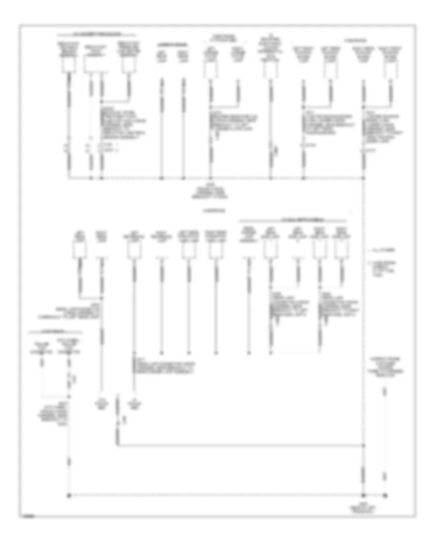
Ground Distribution Wiring Diagram (2 of 5) for Ford F-250 Super Duty King Ranch 2014
List of elements for Ground Distribution Wiring Diagram (2 of 5) for Ford F-250 Super Duty King Ranch 2014:
- (6.7l except high sulfur) nox sensor module 12
- (automatic a/c) autolamp/ sunload sensor
- (crew chief) telematics module
- (crew chief) trailer brake control (tbc) module
- (if equipped) passenger air bag deactivation (pad) switch
- (manual a/c) autolamp sensor
- (pia to steering wheel harness)
- (w/ 110v power inverter instrument panel) dc/ac inverter module
- (w/ base audio & cd player) audio control module (acm)
- (w/ cdim) circuit deactivation ignition module
- 6.2l & 6.8l narrow frame w/ aft fuel tank
- Accessory protocol interface module (apim)
- Audio control module (acm)
- Automatic a/c
- Base audio w/ cd player
- Blower motor speed control
- Brake shift interlock
- C1581
- C210
- C2108
- C213
- C218a
- C218b
- C228a
- C238
- C240a
- C2414a
- C2414b
- C264
- C265
- C465
- C497
- Center stack switch assembly
- Cigar lighter
- Clockspring (top of steering column)
- Data link connector
- Data link connector (dlc)
- Front controls interface module (fcim)
- Fuel pump control module
- Fuel pump module shield
- Fuel tank selector switch
- G201 (center of dash)
- G202 (lower left center of dash)
- G203 (lower left center of dash)
- G401 (middle of left frame rail)
- G402 (left side of frame, near axle)
- Global positioning system module
- Headlamp switch
- Heated steering wheel module (hswm)
- Horn switch
- Hvac module
- Instrument panel cluster (ipc)
- Instrument panel power point 1
- Instrument panel power point 2
- Left steering wheel switch
- Manual a/c
- Mode select switch
- Nca
- Parking aid module (pam)
- Passive anti-theft transceiver
- Power mirror fold relay
- Right steering wheel switch
- S239 (instrument panel wiring harness, in breakout to g203)
- S340 (body main wiring harness, in breakout to c265)
- Shield
- Steering column control module
- Tire pressure monitor module
- Video camera
Ground Distribution Wiring Diagram (3 of 5) for Ford F-250 Super Duty King Ranch 2014
List of elements for Ground Distribution Wiring Diagram (3 of 5) for Ford F-250 Super Duty King Ranch 2014:
- (crew cab w/ consolette) consolette power point
- (crew cab) driver side front power window motor
- (crew cab) master window control switch
- (if equipped) left rear seat heated switch
- (super cab & crew cab) driver side rear door ajar switch
- (super cab & regular cab) master window control switch
- (w/ memory) exterior rear view mirror switch
- (w/o memory) exterior rear view mirror switch
- Auto- dimming interior mirror
- Brake pedal position (bpp) switch
- C264
- C300
- C311
- C341a
- C341b
- C555
- C566b
- C756 c755
- C913
- Center roof marker lamp
- Crew cab
- Driver seat belt buckle switch/ pretensioner
- Driver seat module (dsm)
- Driver side door lock switch
- Driver side exterior rear view mirror
- Driver side front door ajar switch
- Driver side front seat control switch
- G300 (left kick panel)
- High mounted stoplamp
- Keyless entry keypad
- Left center roof marker lamp
- Left roof marker lamp
- Memory set switch
- Nca
- Parking brake switch
- Power seat
- Right center roof marker lamp
- Right roof marker lamp
- S501 (left front door window regulator wiring harness, near breakout to driver's side door lock switch)
- S505 (w/ power equipment) (left front door window regulator wiring harness, near breakout to driver's side front door ajar switch)
- S905 (air curtain & roof markers wiring harness, near breakout to left center roof marker lamp)
- Super cab
- Telescoping exterior rear view mirror switch
- W/ 10-way power seat
- W/ 6-way
Ground Distribution Wiring Diagram (4 of 5) for Ford F-250 Super Duty King Ranch 2014
List of elements for Ground Distribution Wiring Diagram (4 of 5) for Ford F-250 Super Duty King Ranch 2014:
- (5th wheel) trailer tow connector
- (bumper rear park aid wiring harness, near breakout to left license plate lamp)
- (if equipped) electronic locking differential (eld) field coil
- (narrow frame) customer access taped to harness near c422
- 6.7l except high sulfur
- All others
- C139
- C3007
- C3047
- C3138
- C4000
- C4002
- C408
- C432
- C465
- G400 (rear of left frame rail)
- Jumper wiring harness, near breakout to right front running board lamp)
- Left front running board lamp
- Left license plate lamp
- Left rear lamp
- Left rear park/stop/ turn lamp
- Left rear running board lamp
- Left rear side lamp
- Left reversing lamp
- Lh/rh jumper wiring harness, near breakout to left front running board)
- Narrow frame
- Narrow w/ aft fuel tank
- Nca
- Rear marker lamp assembly
- Reductant heater & sensor assembly
- Reductant pressure line heater assembly
- Reductant pump assembly
- Right front running board lamp
- Right license plate lamp
- Right rear lamp
- Right rear park/stop/ turn lamp
- Right rear running board lamp
- Right rear side lamp
- Right reversing lamp
- S400 (rear lamp connector wiring harness, in in breakout to left rear lamp)
- S405 (frame wiring harness, near breakout to g400)
- S411 (rear lamp connector wiring harness, near breakout to rear marker lamp assembly)
- S443 (5th wheel) (frame wiring harness, near breakout to g400)
- Trailer tow connector
- W/ dual rear wheels
- W/ pickup bed
- W/o pickup bed
- Wide frame
- Wide frame w/ pickup bed
- Wide frame/
Ground Distribution Wiring Diagram (5 of 5) for Ford F-250 Super Duty King Ranch 2014
List of elements for Ground Distribution Wiring Diagram (5 of 5) for Ford F-250 Super Duty King Ranch 2014:
- (console wiring harness, near breakout to c3052)
- (crew cab & super cab) passenger side rear door ajar switch
- (if equipped) right rear heated seat switch
- (premium audio w/ sony sound) audio digital signal processing (dsp) module
- (regular cab) front dome lamp
- (super cab & crew cab) front console power point
- (w/ 110v power inverter) dc/ac inverter module
- (w/ rear heated power sliding window) rear window defrost grid
- Body control module
- C2280d
- C248
- C268
- C3049
- C3052
- C312
- C3265a
- C3368b
- C3368d
- C3501a
- C655
- C856 c855
- Crew cab
- Dual climate controlled seat module (dcsm)
- Front interior/ map lamps assembly
- Front passenger side door ajar switch
- Front passenger side power window motor
- Front passenger side seat adjust switch
- G301 (super cab: left "b" pillar) (crew cab: left "c" pillar)
- G302 (right kick panel)
- Left second row seat cushion heater mat
- Left vanity mirror lamp
- Nca
- Overhead console switch assembly
- Passenger side door lock switch
- Passenger side exterior rear view mirror
- Passenger side window control switch
- Rear console power point
- Rear heated seat module
- Rear interior/ map lamps assembly
- Right second row seat cushion heater mat
- Right vanity mirror lamp
- Roof opening panel module
- S638 (w/ power equipment) (right front door jumper wiring harness, near breakout to passenger's front door side impact sensor)
- S639 (w/ power equipment) (right front door jumper wiring harness, near breakout to c646)
- S907 (interior lamp feed headliner wiring harness, near breakout to right vanity mirror lamp)
- Subwoofer amplifier
- Super cab
- W/ power sliding rear window
- W/o moonroof
HEADLIGHTS
Headlights Wiring Diagram for Ford F-250 Super Duty King Ranch 2014
List of elements for Headlights Wiring Diagram for Ford F-250 Super Duty King Ranch 2014:
- (center of dash) g201
- (customer access) (taped to harness near c210)
- Auto
- Auto lp on
- Auto lp sens in
- Autolamp sensor (top center of dash)
- Autolamp/sunload sensor (top center of dash)
- Automatic a/c
- Body control module (right kick panel)
- C134
- C2280a
- C2280b
- C2280c
- C2280e
- C2280f
- C2414a
- Clf19
- Clf21
- Clf23
- Clf24
- Clf34
- Cmc25
- Computer data lines system
- Drv sunload
- Fog ind
- Fog lamp relay
- Fog lamp switch
- Fog lp
- Fuse 10a
- Fuse 15a
- Fuse 5a
- G104 (left rear of engine compt)
- G108 (right rear of engine compt)
- G201 (center of dash)
- G202 (lower left center of dash)
- G300 (left kick panel)
- Gd185
- Head
- Head lp off
- Head lp on
- Headlamp switch
- High
- Hot at all times
- Hs can+
- Hs can-
- Hvac module
- Instrument panel cluster (ipc)
- Interior lights system
- Left fog lamp
- Left headlamp
- Left high beam (fet)
- Left low beam (fet)
- Logic gnd
- Low
- Manual a/c
- Micro
- Multi- function switch
- Off
- Park
- Park brake
- Park lp on
- Parking brake switch (top of parking brake lever assembly)
- Pass sunload
- Right fog lamp
- Right headlamp
- Right high beam (fet)
- Right low beam (fet)
- S1119
- S142 (fog lamp jumper wiring harness, near breakout to c134)
- S239
- Sbp26
- Solid state
- Steering column control module (top of steering column)
- Vbatt
- Vdb04
- Vdb05
- Vh416
- Vh417
- Vlf14
HORN
Horn Wiring Diagram for Ford F-250 Super Duty King Ranch 2014
List of elements for Horn Wiring Diagram for Ford F-250 Super Duty King Ranch 2014:
- Body control module (right kick panel)
- C218a
- C218b
- C218c
- C2280b
- C2280e
- C2414a
- C2414d
- Clockspring (top of steering column)
- Crh04
- Fuse 22 20a
- G108 (right rear of engine compt)
- G202 (lower left center of dash)
- Horn
- Horn (right front of engine compt)
- Horn relay
- Horn switch (steering wheel)
- Hot at all times
- Micro
- Nca
- S299
- Steering column control module (top of steering column)
INSTRUMENT CLUSTER
Instrument Cluster Wiring Diagram (1 of 2) for Ford F-250 Super Duty King Ranch 2014
List of elements for Instrument Cluster Wiring Diagram (1 of 2) for Ford F-250 Super Duty King Ranch 2014:
- (customer access) (taped to harness near c210)
- 4x4 high
- 4x4 low
- Ajar lf door
- Ajar lr door
- Anti-lock brakes system
- Body control module (right kick panel)
- Brake fluid sw
- Brake park
- C1581
- C211
- C218a
- C218b
- C2280a
- C2280b
- C2280c
- C2280f
- C263
- Can+ hs
- Can+ ms
- Can- hs
- Can- ms
- Cca10
- Ccf06
- Ccf22
- Cdc30
- Ce929
- Cet52
- Cet59
- Clockspring (top of steering column)
- Cmc19
- Cmc25
- Cmc29
- Computer data lines system
- Cpl26
- Cpl31
- Cpl36
- Cpl39
- Diesel
- Down
- Fuel level sensor (diesel w/ dual fuel tanks) (in fuel tank)
- Fuel level sensor (in fuel tank)
- Fuel pump (fp) assembly (top of fuel tank)
- Fuel sender 1
- Fuel sender 2
- Fuel sender rtn 1
- Fuel sender rtn 2
- Fuel tank select
- Fuse 10a
- Fuse 15a
- G201 (center of dash)
- G300 (left kick panel)
- Gasoline
- Gd184
- Gnd
- Hill descent sw
- Hot at all times
- Hot in run or start
- Hs can +
- Hs can -
- I can +
- I can -
- Ignition switch
- Info
- Instrument panel cluster (ipc)
- Key in
- Key in ignition
- Left
- Left steering wheel switch
- Message cntrl sw
- Micro
- Ms rtn
- Nca
- Park detect
- Parking brake switch (top of parking brake lever assembly)
- Reset
- Rf door ajar
- Right
- Rmc19
- Rmc27
- Rmc32
- Rmc33
- Rr door ajar
- S304 (body main wiring harness, in breakout to parking brake switch)
- Sbp11
- Setup
- Shift interlock system
- Sw rtn brake fluid
- Tcs
- Vbatt
- Vdb04
- Vdb05
- Vdb06
- Vdb07
- Vdb13
- Vdb14
- Vmc11
- Vmc23
- W/ 3-button message center
- W/ 5-button message center
Instrument Cluster Wiring Diagram (2 of 2) for Ford F-250 Super Duty King Ranch 2014
List of elements for Instrument Cluster Wiring Diagram (2 of 2) for Ford F-250 Super Duty King Ranch 2014:
- (diesel)
- (engine control sensor & fuel charge wiring harness, in breakout to c1168) (6.2l) s120
- (gasoline)
- (instrument panel wiring harness, near breakout to instrument panel power point 1) s245
- (not used)
- 2h (off)
- 4x4 high/low indicator switch (w/ msof) (top rear of transmission)
- 6.2l
- 6.8l & 6.2l
- B-sigrtn
- Brake fluid level switch (brake fluid reservoir)
- C1010
- C1046
- C1047
- C1168
- C1232b
- C1232e
- C145
- C1581
- C175b
- C175e
- C211
- C555
- C655
- C755
- C756
- C855
- C856
- Cmc24
- Computer data lines system
- Crew cab
- Diesel
- Driver side front door ajar switch (lower rear of driver door)
- Driver side rear door ajar switch (super cab & crew cab) (super cab: lower front of driver door) (crew cab: lower rear of driver door)
- Engine controls system
- Eop sw
- Fuel tank selector switch
- Fuel tank selector valve (left rear of frame)
- G104 (left rear of engine compt)
- G203 (lower left center of dash)
- G300 (left kick panel)
- G302 (right kick panel)
- Gasoline
- Hs can +
- Hs can -
- Oil pressure switch (diesel: on oil filter bracket) (gasoline: lower left front of engine)
- Passenger side front door ajar switch (lower rear of passenger door)
- Passenger side rear door ajar switch (super cab & crew cab) (super cab: lower front of passenger door) (crew cab: lower rear of passenger door)
- Powertrain control module (right rear of engine compt)
- Primary
- Re407
- S100 (engine control sensor engine compartment wiring harness, near breakout to right headlamp)
- S246
- S505 (w/ power equipment)
- S638 (w/ power equipment)
- S802 (w/ heated seats)
- Seats system
- Seats)
- Secondary
- Super cab
- Vdb04
- Vdb05
- Ve823
- Water-in fuel sensor (diesel) (middle of left frame rail)
- Wfs
INTERIOR LIGHTS
Courtesy Lamps Wiring Diagram (1 of 2) for Ford F-250 Super Duty King Ranch 2014
List of elements for Courtesy Lamps Wiring Diagram (1 of 2) for Ford F-250 Super Duty King Ranch 2014:
- (body main wiring harness, near breakout to c312) s370
- (right kick panel) g302
- Battery saver relay
- Body control module (bcm) (right kick panel)
- C2280a
- C2280b
- C2280c
- C2280d
- C2280f
- C2414a
- C248
- C265
- C268
- Car2u lear
- Cln55
- Cln56
- Computer data lines system
- Dim down
- Dim rtn
- Dim up
- Dome
- Dome on/ defeat
- Engine compartment lamp
- Front dome lamp
- Front interior/ map lamps assembly
- Fuse 10a
- Fuse 15a
- Fuse 2a
- Fuse 5a
- G104 (left rear of engine compt)
- G202 (lower left center of dash)
- G300 (left kick panel)
- Gd185
- Gnd
- High mounted stoplamp
- Hot at all times
- Hs can+
- Hs can-
- Instrument illumination circuit
- Instrument panel dimmer switch
- Interior lighting (fet)
- Left vanity mirror lamp
- Logic gnd
- Micro
- Multi function switch
- Off
- Puddle lamp (fet)
- Pwm input
- Rear interior/ map lamps assembly (crew cab)
- Red
- Regular cab
- Right vanity mirror lamp
- Rln29
- S239
- S907
- S908 (interior lamp feed headliner wiring harness, near breakout to rear of roof & map lamps assembly)
- S909 (interior lamp feed headliner wiring harness, near breakout to right vanity mirror lamp)
- Sbp26
- Steering column control module (top of steering column)
- Super cab & crew cab
- Vbatt
- Vdb04
- Vdb05
- Vln36
Courtesy Lamps Wiring Diagram (2 of 2) for Ford F-250 Super Duty King Ranch 2014
List of elements for Courtesy Lamps Wiring Diagram (2 of 2) for Ford F-250 Super Duty King Ranch 2014:
- (left kick panel) g300
- Ajar lf door
- Ajar lr door
- Body control module (bcm) (right kick panel)
- C1415
- C210
- C2280c
- C2280f
- C3137
- C3138
- C555
- C655
- C755
- C756
- C855
- C856
- Can+ hs
- Can- hs
- Computer data lines system
- Cpl26
- Cpl31
- Cpl36
- Cpl39
- Crew cab
- Driver side front door ajar switch (lower rear of driver door)
- Driver side rear door ajar switch (super cab (& crew cab) (crew cab: lower rear of driver door) (super cab: lower front of driver door)
- G300 (left kick panel)
- G302 (right kick panel)
- G400 (rear of left frame rail)
- Hs can +
- Hs can -
- Instrument panel cluster (ipc)
- Left front running board lamp
- Left rear running board lamp
- Micro
- Passenger side front door ajar switch (lower rear of passenger door)
- Passenger side rear door ajar switch (super cab (& crew cab) (crew cab: lower rear of passenger door) (super cab: lower front of passenger door)
- Rf door ajar
- Right front running board lamp
- Right rear running board lamp
- Rr door ajar
- S311
- S312 (lighted running board lh/rh jumper wiring harness, near breakout to right front running board lamp)
- S313
- S328 (lighted running board lh/rh jumper wiring harness, near breakout to left front running board lamp)
- S396 (6.2l flex fuel & 6.8l: frame wiring harness, near breakout to c327) (6.7l turbo diesel: frame wiring harness, near breakout to c328)
- S405
- S505
- S638
- S700
- S802
- Super cab
- Vdb04
- Vdb05
- W/ power equipment
- W/ rear heated seats
- W/o power equipment
- W/o rear heated seats
Instrument Illumination Wiring Diagram for Ford F-250 Super Duty King Ranch 2014
List of elements for Instrument Illumination Wiring Diagram for Ford F-250 Super Duty King Ranch 2014:
- (center of dash) g201
- (not used)
- (right "c" pillar) roof opening panel module
- (super cab: left "b" pillar) (crew cab: left "c" pillar) g301
- (w/ am/fm/cd) audio control module (acm)
- Auto
- Auto lp on
- Back- lighting led (fet)
- Body control module (bcm) (right kick panel)
- C218a
- C218b
- C2280b
- C2280f
- C2414a
- C265
- C268
- Center stack switch assembly
- Clf19
- Clf23
- Clf24
- Clf34
- Cln55
- Cln56
- Clockspring (top of steering column)
- Common
- Computer data lines system
- Cpr39
- Dim down
- Dim rtn
- Dim up
- Dome
- Done on/defeat
- Fuse 15a
- Fuse 5a
- G201 (center of dash)
- G202 (lower left center of dash)
- G203 (lower left center of dash)
- G204 (lower left center of dash)
- G302 (right kick panel)
- Gd115
- Gd143
- Gd185
- Gnd
- Hdlp off
- Hdlp on
- Head
- Headlamp switch
- Hot at all times
- Hs can+
- Hs can-
- Ill+
- Ill-
- Instrument panel dimmer switch
- Left steering wheel switch
- Logic gnd
- Micro
- Mode select switch
- Multi- function switch
- Off
- Overhead console switch assembly
- Park
- Park lp on
- Pwm input
- Right steering wheel switch
- Rln29
- S220 (instrument panel wiring harness, near breakout to g201)
- S239
- S249
- S299
- S907
- Sbp26
- Steering column control module (top of steering column)
- Upfitter switch
- Vbatt
- Vdb04
- Vdb05
- Vln04
- Vln36
- W/ 5-button message center
- W/ moonroof
- W/o moonroof
- White led (fet)
MEMORY SYSTEMS
Adjustable Pedal Wiring Diagram for Ford F-250 Super Duty King Ranch 2014
List of elements for Adjustable Pedal Wiring Diagram for Ford F-250 Super Duty King Ranch 2014:
- (lower left center of dash) g202
- Adjustable pedal motor (left side of dash)
- Adjustable pedal switch
- Body control module (right kick panel)
- C212
- C2280a
- C2414a
- C2414b
- C2414c
- C300
- C341c
- C341d
- C555
- Com mtr pdl/col
- Computer data lines system
- Cpp01
- Cpp02
- Cps15
- Cps16
- Driver seat module (dsm) (under driver's seat)
- Fuse 15a
- G300 (left kick panel)
- Gd185
- Gnd
- Hall sns rtn
- Hot at all times
- Hs can +
- Hs can -
- Lpp06
- Memory set switch
- Ms can +
- Ms can -
- Pdl hall sns sig
- Pedal mtr (fwd)
- Rpp06
- S228
- S239
- S505 (w/ power equipment)
- Sbp24
- Set 1
- Set 2
- Steering column control module (top of steering column)
- Vbatt
- Vdb04
- Vdb05
- Vdb06
- Vdb07
Driver"s Memory Seat Wiring Diagram (1 of 2) for Ford F-250 Super Duty King Ranch 2014
List of elements for Driver"s Memory Seat Wiring Diagram (1 of 2) for Ford F-250 Super Duty King Ranch 2014:
- Aft
- Base backward
- Base forward
- Body control module (right kick panel)
- C2280d
- C300
- C3050
- C311
- C341a
- C341b
- Cbx03
- Cbx05
- Cps01
- Cps02
- Cps03
- Cps04
- Cps05
- Cps06
- Cps07
- Cps08
- Cps23
- Cps24
- Cps25
- Cps26
- Cps27
- Cps28
- Cps29
- Cps30
- Deflate
- Driver seat front height motor
- Driver seat horizontal motor
- Driver seat lumbar motor
- Driver seat module (dsm) (under driver's seat)
- Driver seat rear height motor
- Driver seat recliner motor
- Driver side front seat control switch
- Forward
- Front dn
- Front height
- Front up
- Fuse 5a
- Fuse 7.5a
- Fwd
- G300 (left kick panel)
- Gd905
- Gd906
- Hall effect rtn
- Hall effect sns
- Height rear
- Horizontal
- Hot at all times
- Incline
- Inflate
- Logic gnd
- Lumbar
- Pwr gnd
- Rear dn
- Rear up
- Recline
- Rps13
- S368 (driver cushion wiring harness, near breakout to c3050)
- Vbatt
- Vps09
- Vps10
- Vps11
- Vps12
Driver"s Memory Seat Wiring Diagram (2 of 2) for Ford F-250 Super Duty King Ranch 2014
List of elements for Driver"s Memory Seat Wiring Diagram (2 of 2) for Ford F-250 Super Duty King Ranch 2014:
- (not used)
- Adjustable pdl fwd sw
- Battery junction box (bjb) (left side of engine compt)
- C210
- C300
- C311
- C341c
- C341d
- C555
- Computer data lines system
- Cpm04
- Cpm16
- Cpm17
- Cpm20
- Cpm21
- Cpm22
- Cpm26
- Cpm28
- Cpm29
- Cpm31
- Cpm33
- Cpm34
- Cpm39
- Cpp09
- Cps14
- Cps15
- Cps16
- Driver seat module (dsm) (under driver's seat)
- Drv hor pot
- Drv mirr hor sw
- Drv mirr mtr hor rt
- Drv mirr mtr vert up
- Drv mirr vert sw
- Drv mtr dn/lt
- Drv vert pot
- Ext mirr pot feed
- Fuse 30a
- G300 (left kick panel)
- Hot at all times
- Lpm30
- Memory mirrors circuit
- Memory set switch
- Mirr com sw
- Mirr fold sw
- Mirr mtr fold in
- Mirr mtr fold out
- Mirr pot ret
- Ms can +
- Ms can -
- Pass hor pot
- Pass mirr hor sw
- Pass mirr mtr dn/lt
- Pass mirr mtr hor rt
- Pass mirr mtr vert up
- Pass mirr vert sw
- Pass vert pot
- Red
- Rpm11
- Rpm30
- S505 (w/ power equipment)
- Set
- Set 1
- Set 2
- Vdb06
- Vdb07
- Vpm35
- Vpm36
- Vpm37
- Vpm38
Memory Mirrors Wiring Diagram for Ford F-250 Super Duty King Ranch 2014
List of elements for Memory Mirrors Wiring Diagram for Ford F-250 Super Duty King Ranch 2014:
- (body main wiring harness, near breakout to c311)
- (body main wiring harness, near breakout to restraints control module)
- (left front door window regulator wiring harness, near breakout to exterior rear view mirror switch)
- (right front door jumper wiring harness, in breakout to passenger's side exterior rear view mirror)
- Battery junction box (bjb) (left side of engine compt)
- Body control module (right kick panel)
- C210
- C2280d
- C300
- C311
- C341a
- C341b
- C341c
- C341d
- C555
- C655
- Cbx03
- Cbx05
- Computer data lines system
- Cpm16
- Cpm17
- Cpm20
- Cpm21
- Cpm26
- Cpm28
- Cpm29
- Cpm31
- Cpm33
- Cpm34
- Cps15
- Cps16
- Defogger system
- Driver seat module (dsm) (under driver's seat)
- Driver side exterior rear view mirror
- Drv mirr hor pot
- Drv mirr hor sw
- Drv mirr vert pot
- Drv mirr vert sw
- Drv mtr dn/lt
- Drv mtr hor rt
- Drv mtr vert up
- Ext mirr pot feed
- Exterior lights system
- Exterior rear view mirror switch
- Fuse 10a
- Fuse 30a
- Fuse 5a
- G300 (left kick panel)
- G302 (right kick panel)
- Gd906
- Hot at all times
- Left/right
- Lpm30
- Memory set switch
- Mirr com sw
- Mirr pot rtn
- Mirror heated
- Mirrors system
- Ms can +
- Ms can -
- Nca
- Park
- Pass hor pot
- Pass mirr hor sw
- Pass mirr vert sw
- Pass mtr dn/lt
- Pass mtr hor rt
- Pass mtr vert up
- Pass vert pot
- Passenger side exterior rear view mirror
- Pwr gnd
- Red
- Rpm11
- Rpm30
- S318
- S336
- S501
- S505
- S513
- S609
- S639
- Set 1
- Set 2
- Turn
- Up/dn
- Vbatt
- Vdb06
- Vdb07
- Vpm35
- Vpm36
- Vpm37
- Vpm38
NAVIGATION
Crew Chief Wiring Diagram for Ford F-250 Super Duty King Ranch 2014
List of elements for Crew Chief Wiring Diagram for Ford F-250 Super Duty King Ranch 2014:
- 5vpwr
- 5vtb
- Battery junction box (bjb) (left side of engine compt)
- Body control module (bcm) (right kick panel)
- C2280b
- Cgnd
- Computer data lines system
- Fuse 30a
- Fuse 5a
- G203 (lower left center of dash)
- Gnd
- Gnd1
- Hot at all times
- Hot in start or run
- Hs can+
- Hs can-
- Hsc1-c
- Hsc2-c
- Igrun-c
- Inline fuse (right end of dash)
- Modem-antenna (top center of dash)
- Nca
- Pwr ground
- Red
- Run start
- Rxd
- S272
- S273
- S274
- Telematics module (right end of dash)
- Txd
- Vb1
- Vbatt
Navigation Wiring Diagram, with Sony (1 of 3) for Ford F-250 Super Duty King Ranch 2014
List of elements for Navigation Wiring Diagram, with Sony (1 of 3) for Ford F-250 Super Duty King Ranch 2014:
- (body main wiring harness, near breakout to c311) s291
- (right rear cab)
- Audio digital signal processing (dsp) module (crew cab: base of right "c" pillar) (super cab: center rear of cab floor)
- Body control module (right kick panel)
- C207
- C2280a
- C2280b
- C2280d
- C3154a
- C3154b
- C3154c
- C555
- C655
- C755
- C855
- Cls32
- Computer data lines system
- Enable
- Fuse 15a
- Fuse 20a
- Fuse 5a
- G201 (center of dash)
- G302 (right kick panel)
- Gd114
- Gd139
- Global positioning system module (gpsm) (w/ sync) (top center of dash)
- Gnd
- Hazard
- Hot at all times
- I can +
- I can -
- Instrument panel speaker
- Ip spkr +
- Ip spkr -
- Left front speaker
- Left front tweeter
- Left rear speaker
- Left rear tweeter
- Lf spkr +
- Lf spkr -
- Lf tweeter +
- Lf tweeter -
- Lr spkr +
- Lr spkr -
- Ms can+
- Ms can-
- Nca
- Rf spkr +
- Rf spkr -
- Rf tweeter +
- Rf tweeter -
- Right front speaker
- Right front tweeter
- Right rear speaker
- Right rear tweeter
- Rme06
- Rme07
- Rme08
- Rme09
- Rme10
- Rme11
- Rme12
- Rme17
- Rme18
- Rme22
- Rme55
- Rme80
- Rr spkr +
- Rr spkr -
- S222
- S228
- S292
- S300
- S301
- Sbp19
- Sbp29
- Sme23
- Subw 1+
- Subw 1-
- Subw 2+
- Subw 2-
- Sync alert +
- Sync alert -
- Sync radio circuit
- V batt
- Vbatt
- Vdb06
- Vdb07
- Vdb13
- Vdb14
- Vme06
- Vme07
- Vme08
- Vme09
- Vme10
- Vme11
- Vme12
- Vme17
- Vme18
- Vme22
- Vme55
- Vme80
Navigation Wiring Diagram, with Sony (2 of 3) for Ford F-250 Super Duty King Ranch 2014
List of elements for Navigation Wiring Diagram, with Sony (2 of 3) for Ford F-250 Super Duty King Ranch 2014:
- (base of right "c" pillar) subwoofer amplifier
- (top of steering column)
- Audio pwr
- Audio rtn
- C218c
- C2414a
- C2414b
- C2414d
- Clockspring (top of steering column)
- Cls32
- Computer data lines system
- Front controls interface module (fcim)
- G201 (center of dash)
- G202 (lower left center of dash)
- Gd184
- Gd185
- Gnd
- Hazard
- Hazard switch
- Hs can +
- Hs can -
- I can +
- I can -
- Interior lights system
- Logic gnd
- Media
- Nca
- Phone
- Pwr gnd
- Right steering wheel switch
- S239
- Sbp24
- Sbp26
- Seek+
- Seek-
- Steering column control module
- Subw 1+
- Subw 1-
- Subw 2+
- Subw 2-
- Sync pwr
- Sync rtn
- Vbatt
- Vdb04
- Vdb05
- Vdb13
- Vdb14
- Voice
- Vol+
- Vol-
Navigation Wiring Diagram, with Sony (3 of 3) for Ford F-250 Super Duty King Ranch 2014
List of elements for Navigation Wiring Diagram, with Sony (3 of 3) for Ford F-250 Super Duty King Ranch 2014:
- Am/fm antenna
- Amp gnd
- Antenna
- Audio control module (acm)
- Batt
- Battery junction box (bjb) (left side of engine compt)
- C211
- C265
- C290a
- C290b
- Cdc38
- Computer data lines system
- Dme17
- Enable
- G201 (center of dash)
- Gd114
- I can+
- I can-
- Lf spkr +
- Lf spkr -
- Nca
- Rf spkr +
- Rf spkr -
- Rme17
- Rme18
- Rme52
- Rme53
- Sbp29
- Sdars ant
- Sdars antenna
- Sdl-h
- Sdl-l
- Shield
- Sme23
- Start
- Starting/ charging system
- Stereo l+
- Stereo l-
- Stereo r+
- Stereo r-
- Sync radio circuit
- Vdb13
- Vdb14
- Vme17
- Vme18
- Vme52
- Vme53
- Vme90
- Vme91
Navigation Wiring Diagram, without Sony (1 of 2) for Ford F-250 Super Duty King Ranch 2014
List of elements for Navigation Wiring Diagram, without Sony (1 of 2) for Ford F-250 Super Duty King Ranch 2014:
- (audio jumper wiring harness, in breakout to right front tweeter) s602
- Am/fm antenna
- Amp gnd
- Antenna
- Audio control module (acm)
- Batt
- Battery junction box (bjb) (left side of engine compt)
- Body control module (right kick panel)
- C211
- C212
- C2280a
- C2280b
- C2280d
- C265
- C290a
- C510
- C555
- C610
- C655
- C756
- C856
- Cdc38
- Cls32
- Computer data lines system
- Front controls interface module (fcim)
- Fuse 15a
- Fuse 20a
- Fuse 5a
- G201 (center of dash)
- Gd114
- Gd184
- Global positioning system module (gpsm) (w/ sync) (top center of dash)
- Gnd
- Hazard
- Hazard switch
- Hot at all times
- I can +
- I can -
- I can+
- I can-
- Left front speaker
- Left front tweeter
- Left rear speaker
- Lf spkr +
- Lf spkr -
- Lr spkr +
- Lr spkr -
- Ms can+
- Ms can-
- Rf spkr +
- Rf spkr -
- Right front speaker
- Right front tweeter
- Right rear speaker
- Rme09
- Rme12
- Rme17
- Rme18
- Rr spkr +
- Rr spkr -
- S222
- S228
- S502 (audio jumper wiring harness, in breakout left front tweeter)
- S503
- S603
- Sbp24
- Sbp29
- Sdars ant
- Sdars antenna
- Start
- Starting/charging system
- Vbatt
- Vdb06
- Vdb07
- Vdb13
- Vdb14
- Vme09
- Vme12
- Vme17
- Vme18
Navigation Wiring Diagram, without Sony (2 of 2) for Ford F-250 Super Duty King Ranch 2014
List of elements for Navigation Wiring Diagram, without Sony (2 of 2) for Ford F-250 Super Duty King Ranch 2014:
- (base of right "c" pillar) subwoofer amplifier
- (crew cab: left "c" pillar) (super cab: left "b" pillar)
- (top of steering column) steering column control module
- Audio control module (acm)
- Audio pwr
- Audio rtn
- Aux aud sh
- C212
- C218b
- C218c
- C2414a
- C2414b
- C2414d
- C265
- C290b
- Clockspring (top of steering column)
- Computer data lines system
- Dme22
- Enable/ clip detect
- G202 (lower left center of dash)
- G301
- Gd185
- Gnd
- Hs can +
- Hs can -
- Interior lights system
- Logic gnd
- Media
- Nca
- Phone
- Pwr gnd
- Right steering wheel switch
- Rme22
- Rme52
- Rme53
- Rme80
- S239
- Sbp24
- Sbp26
- Sdl-l
- Seek+
- Seek-
- Sme23
- Spl-h
- Stereo l+
- Stereo l-
- Stereo r+
- Stereo r-
- Subw +
- Subw -
- Subw - enable/ clip detect
- Sync alert +
- Sync alert -
- Sync pwr
- Sync radio circuit
- Sync rtn
- Vbatt
- Vdb04
- Vdb05
- Vme22
- Vme52
- Vme53
- Vme80
- Vme90
- Vme91
- Voice
- Vol+
- Vol-
Parking Assistant Wiring Diagram for Ford F-250 Super Duty King Ranch 2014
List of elements for Parking Assistant Wiring Diagram for Ford F-250 Super Duty King Ranch 2014:
- (bumper rear park aid wiring harness, near breakout to left license plate lamp) s415
- (left side of rear bumper)
- Body control module (bcm) (right kick panel)
- C1581
- C211
- C2280b
- C408
- Cbp35
- Cmp09
- Computer data lines system
- Fuse 5a
- G201 (center of dash)
- Gd184
- Gnd
- Hot in start or run
- Hs can+
- Hs can-
- Inner left parking aid sensor
- Inner right parking aid sensor (right side of rear bumper)
- Lmp07
- Outer left parking aid sensor (left side of rear bumper)
- Outer right parking aid sensor (right side of rear bumper)
- Parking aid module (pam) (lower left end of dash)
- Parking aid speaker (left end of dash)
- Ril sensor in
- Rir sensor in
- Rmp07
- Rmp09
- Rol sensor in
- Ror sensor in
- S227
- S416 (bumper rear park aid wiring harness, near breakout to c408)
- Sensor gnd
- Sensor pwr
- Sndr+
- Sndr-
- Solid state
- Vdb04
- Vdb05
- Vmp14
- Vmp15
- Vmp16
- Vmp17
- Vpwr
Rear Camera Wiring Diagram for Ford F-250 Super Duty King Ranch 2014
List of elements for Rear Camera Wiring Diagram for Ford F-250 Super Duty King Ranch 2014:
- (body main wiring harness, in breakout to c264) s373
- Accessory protocol interface module (premium audio) (right end of dash)
- Auto dimming interior mirror
- Base audio
- Battery junction box (bjb) (left side of engine compt)
- Body control module (right kick panel)
- C1581
- C210
- C2280c
- C264
- C265
- C465
- C497
- Cbb49
- Dmp19
- Fuse 10a
- G201 (center of dash)
- Hot in start or run
- Lin
- Micro
- Nca
- Rmp19
- S340 (body main wiring harness, in breakout to c265)
- S372
- Shield
- Vdn03
- Video +
- Video -
- Video camera (middle of tail gate)
- Video+
- Video-
- Vmp19
- Vpwr
POWER DISTRIBUTION
Power Distribution Wiring Diagram (1 of 9) for Ford F-250 Super Duty King Ranch 2014
List of elements for Power Distribution Wiring Diagram (1 of 9) for Ford F-250 Super Duty King Ranch 2014:
- (6.2l flex fuel & 6.8l) (6.7l turbo diesel)
- (6.7l turbo diesel: battery cable wiring assembly, in breakout to battery) (except 6.7l turbo diesel: alternator rectifier system wiring assembly, in breakout to battery)
- (alternator rectifier system wiring harness, near breakout to battery)
- (crew chief)
- (left side of engine compt) battery junction box (bjb)
- (right side of engine compt) high current battery junction box
- (w/ 10 way power seat)
- (w/ 6 way
- 6.7l turbo diesel w/ dual generators
- Auxiliary heater control module (ahcm) (6.7l turbo diesel w/ rapid heat)
- Battery
- Battery junction box (bjb) (left side of engine compt)
- Blower motor relay
- C1273a
- C1617a
- C1617b
- C1617c
- C1617d
- C1617e
- C1617f
- C210
- C2108
- C211
- C2463a
- C311
- C312
- C341a
- C555
- Crew chief
- Driver side front power window motor
- Driver side front seat control switch (w/o memory)
- Driver's seat module (dsm) (w/ memory)
- Front wiper relay
- Fuse 25a
- Fuse 30a
- Fuse 40a
- Fuse 40a 50a
- Fusible link b (20 ga- red) (right front of engine, in battery wiring assembly)
- Fusible link c (12 ga- red) (right front of engine, in battery wiring assembly)
- Fusible link d (12 ga- red) (right front of engine, in battery wiring assembly)
- Generator
- Glow plug control module (6.7l turbo diesel)
- Inline fuse (right end of dash)
- Mega fuse 125a
- Mega fuse 175a 275a
- Mega fuse 200a
- Nca
- Parking lamp trailer tow relay
- Passenger side front seat control switch
- Power seat)
- Rear window defrost relay
- Red
- Reductant heater relay (6.7l turbo diesel)
- S137
- S138
- S139
- S140 (alternator rectifier system wiring harness, near breakout to c144)
- S141 (alternator rectifier system wiring harness, between fusible link b & c)
- S272 (t-box jumper wiring harness, near breakout to c2108)
- Secondary battery (6.7l)
- Secondary generator
- Starter motor
- Telematics module
- To body control module (diagram 5 of 9)
- To fuse 39 (diagram 2 of 9)
- Trailer brake control (tbc) module
- W/ rear heated power sliding window
- W/o rear heated power sliding window
Power Distribution Wiring Diagram (2 of 9) for Ford F-250 Super Duty King Ranch 2014
List of elements for Power Distribution Wiring Diagram (2 of 9) for Ford F-250 Super Duty King Ranch 2014:
- (crew chief)
- (left side of engine compt) battery junction box (bjb)
- (not used)
- (t-box jumper wiring harness, near breakout to c2108) (crew chief) s274
- 6.7l turbo diesel
- 6.8l & 6.2l flex fuel
- Anti-lock brake system (abs) module
- Auxiliary heater control module (ahcm) (6.7l turbo diesel w/ rapid heat)
- Battery charge trailer tow relay
- Battery junction box (bjb) (left side of engine compt)
- Blower motor relay
- Body control module (right kick panel)
- C1010
- C1232b
- C1415
- C1581
- C175b
- C2108
- C214
- C2280b
- C2280d
- C2280e
- C2280f
- C2371a
- C2371b
- C2463b
- C3049
- C310a
- C3162b
- C465
- C497
- Center stack switch assembly
- Constant vacuum hub lock (cvh) solenoid
- From fuse 23 (diagram 1 of 9)
- Fuel tank selector switch
- Fuse 10a
- Fuse 15a
- Fuse 20a
- Fuse 5a
- Fuse 7.5a
- Heated steering wheel module (hswm)
- Micro
- Nca
- Parking aid module (pam)
- Powertrain control module (pcm)
- Rear heated seat module
- Rear window defrost relay
- Restraints control module
- Run/ start (fet)
- Run/ start relay
- S227 (instrument panel wiring harness, near breakout to inertia fuel shutoff switch)
- Telematics module (crew chief)
- To fuse 46 (diagram 3 of 9)
- Tow haul switch
- Trailer brake control (tbc) module
- Transfer case control module
- Transmission control module (tcm) (6.7l turbo diesel)
- Video camera
Power Distribution Wiring Diagram (3 of 9) for Ford F-250 Super Duty King Ranch 2014
List of elements for Power Distribution Wiring Diagram (3 of 9) for Ford F-250 Super Duty King Ranch 2014:
- (customer access)
- (engine control sensor engine compt wiring harness, in breakout to powertrain control module) s105
- (engine control sensor engine compt wiring harness, near breakout to c1581) s122
- (engine wiring harness, near breakout to fuel injector 1) s110
- (engine wiring harness, near breakout to intake throttle actuator) s109
- (left side of engine compt) battery junction box (bjb)
- (not used)
- 6.7l turbo diesel
- 6.8l & 6.2l flex fuel
- A/c clutch relay
- Battery junction box (bjb) (left side of engine compt)
- C1010
- C1047
- C110
- C1165
- C1232b
- C1273c
- C139
- C1415
- C1581
- C175b
- C3047
- C3611a
- C3619a
- Cooling fan
- Egr cooler bypass valve solenoid
- Evap canister vent control solenoid (except 6.7l turbo diesel)
- From c fuse 40 (diagram 2 of 9)
- From d fuse 68 (diagram 3 of 9)
- Fuel pressure control valve
- Fuel pump (fp) motor diode
- Fuel pump (fp) relay
- Fuel volume control valve
- Fuse 10a
- Fuse 15a
- Fuse 20a
- Fuse n/a
- Glow plug control module
- Mass air flow/ intake air temperature (maf/iat) sensor
- Narrow frame w/o aft fuel tank
- Nca
- Nox 11 sensor module (except high sulfur)
- Nox 12 sensor module (except high sulfur)
- Pcm power relay
- Powertrain control module
- Red
- Reductant pump assembly (except high sulfur)
- Reductant purge valve (except high sulfur)
- Reversing lamp relay
- S3000
- To fuse 33 (diagram 4 of 9)
- To fuse 72 (diagram 3 of 9)
- To fuse 84 (diagram 4 of 9)
- Transmission control module (6.7l turbo diesel)
- Turbo- charger actuator
- Turbo- charger wastegate regulating valve solenoid
- Wide frame & narrow frame w/ aft fuel tank
Power Distribution Wiring Diagram (4 of 9) for Ford F-250 Super Duty King Ranch 2014
List of elements for Power Distribution Wiring Diagram (4 of 9) for Ford F-250 Super Duty King Ranch 2014:
- (customer access)
- (engine control sensor & fuel charge wiring harness, near breakout to c133) s117
- (engine control sensor & fuel charge wiring harness, near breakout to fuel injector 1) (6.8l) s127 (6.2l flex fuel) s118
- (engine control sensor & fuel charge wiring harness, near breakout to fuel injector 1) s112
- (engine control sensor & fuel charge wiring harness, near breakout to fuel injector 5)
- (engine control sensor & fuel charge wiring harness, near breakout to fuel injector 7) (6.8l) s135 (6.2l flex fuel) s114
- (engine control sensor engine compt wiring harness, near breakout to c1581)
- (engine control sensor engine compt wiring harness, near breakout to horn) s101
- (left side of engine compt) battery junction box (bjb)
- (not used)
- (passenger cushion wiring harness, near breakout to dual climate controlled seat module)
- (transmission wiring harness, near breakout to heated oxygen sensor 12) (6.2l flex fuel) s181
- 6.2l flex fuel
- 6.8l
- A/c clutch relay
- Anti-lock brake system (abs) module
- Battery charge trailer tow relay
- Battery junction box (bjb) (left side of engine compt)
- C1168
- C1220
- C145
- C1581
- C175b
- C210
- C2371b
- C312
- C3162b
- C3265a e
- Coil on plug (cop) 1
- Coil on plug (cop) 10 (6.8l)
- Coil on plug (cop) 2
- Coil on plug (cop) 3
- Coil on plug (cop) 4
- Coil on plug (cop) 5
- Coil on plug (cop) 6
- Coil on plug (cop) 7
- Coil on plug (cop) 8
- Coil on plug (cop) 9 (6.8l)
- Cooling fan
- Dual climate controlled seat module (dcsm)
- Evaporative emission (evap) canister purge valve
- From e fuse 72 (diagram 3 of 9)
- From g fuse 34 (diagram 4 of 9)
- From pcm f power relay (diagram 3 of 9)
- Fuse 10a
- Fuse 15a
- Fuse 20a
- Fuse 25a
- Fuse 30a
- Fuse 40a
- Fuse 50a
- Fuse n/a
- Heated oxygen sensor (ho2s) 12 (6.2l flex fuel)
- Heated oxygen sensor (ho2s) 12 (narrow frame)
- Heated oxygen sensor (ho2s) 22 (6.2l flex fuel)
- Ignition transformer capacitor
- Ignition transformer capacitor 1
- Intake manifold tuning valve (imtv)
- Left turn trailer tow relay
- Mass air flow/ intake air temperature (maf/iat) sensor
- Nca
- Not used
- Powertrain control module
- Rear heated seat module
- Red
- Right turn trailer tow relay
- S104
- S315 (rear seat wiring harness, in breakout to c3049)
- S341
- Starter relay
- To fuse 35 (diagram 4 of 9)
- To fuse 83 (diagram 5 of 9)
- Transfer case control module (tccm)
- Universal heated oxygen sensor (ho2s) 11 (6.2l flex fuel)
- Universal heated oxygen sensor (ho2s) 11 (6.8l)
- Universal heated oxygen sensor (ho2s) 21
- Variable camshaft timing 11 (vct 11) solenoid
- Variable camshaft timing 21 (vct 21) solenoid
Power Distribution Wiring Diagram (5 of 9) for Ford F-250 Super Duty King Ranch 2014
List of elements for Power Distribution Wiring Diagram (5 of 9) for Ford F-250 Super Duty King Ranch 2014:
- (base)
- (instrument panel wiring harness, near breakout to inertia fuel shutoff switch) s228
- (instrument panel wiring harness, near breakout to passenger airbag module) (w/ sync) s222
- (left side of engine compt) battery junction box (bjb)
- (not used)
- (or sbb99)
- (premium)
- (right kick panel) body control module
- Ac outlet
- Ac-a
- Ac-b
- Acc
- Accessory protocol interface module (apim) (w/ sync)
- Audio control module
- Automatic a/c
- C210
- C211
- C215
- C2280a
- C2280b
- C2280g
- C228a
- C2293a
- C2293b
- C238
- C240a
- C2414a
- C2414b
- C290a
- C3052
- C3501a
- C3501b
- Cbp32
- Cigar lighter
- Consolette power point (crew cab w/ consolette)
- Data link connector (dlc)
- Dc/ac inverter module (w/ 110v power inverter) (w/ center console: under center console) (w/o center console: bottom left end of dash)
- From h fuse 90 (diagram 4 of 9)
- From high current battery junction box (diagram 1 of 9)
- From splice s314 l (diagram 7 of 9)
- From splice s383 m (diagram 7 of 9)
- Front console power point (super cab & crew cab)
- Front control interface module (premium audio)
- Fuse 10a
- Fuse 15a
- Fuse 20a
- Fuse 25a
- Fuse 40a
- Fuse 5a
- G203 (lower left center of dash)
- G300 (left kick panel)
- G302 (right kick panel)
- Gd179 (or gd115)
- Global positioning system (gpsm) module (w/ sync)
- Gnd
- Hot
- Hvac module
- Hya01
- Hya02
- Instrument panel cluster (ipc)
- Instrument panel power point 1
- Instrument panel power point 2
- Led+
- Led-
- Lin 01
- Lya03
- Manual a/c
- Neut
- Power mirror fold relay
- Rear console power point
- Red
- Rya03
- S390
- Sbb97
- Steering column control module (sccm)
- Tire pressure monitor (tpm) module
- To fuse 7 (diagram 6 of 9)
- To upfitter relay box (diagram 9 of 9)
- Vdn01
- W/ instrument panel
- W/o instrument panel
Power Distribution Wiring Diagram (6 of 9) for Ford F-250 Super Duty King Ranch 2014
List of elements for Power Distribution Wiring Diagram (6 of 9) for Ford F-250 Super Duty King Ranch 2014:
- (crew chief)
- (interior lamp feed headliner wiring harness, near breakout to rear interior & map lamps assembly) (super cab & crew cab) s908
- (not used)
- (right kick panel) body control module
- (taped to harness near c422)
- (taped to harness near c465)
- 6.7l turbo diesel 6.8l & 6.2l flex fuel
- All lock/unlock relay
- Audio digital signal processing (dsp) module
- Battery saver relay
- Brake pedal position (bpp) switch
- C1232b
- C1415
- C175b
- C210
- C2108
- C212
- C215
- C2280b
- C2280d
- C2280f
- C248 c268
- C265
- C300
- C3154c
- C341b
- C465
- C555
- C655
- Driver door unlock relay
- Driver seat module (dsm) (w/ memory)
- Driver side front seat control switch (w/ memory)
- Engine compartment lamp
- Exterior rearview mirror switch
- Fog lamp relay
- From n fuse 27 (diagram 5 of 9)
- From o fuse 9 (diagram 6 of 9)
- From r fuse 20 (diagram 6 of 9)
- Front dome lamp (regular cab)
- Front interior/ map lamps assembly (super cab & crew cab)
- Fuse 10a
- Fuse 15a
- Fuse 20a
- Fuse 30a
- Fuse 5a
- Fuse 7.5a
- Left corner lamp (fet)
- Left vanity mirror lamp (super cab & crew cab)
- Micro
- Narrow frame
- Park lamp relay
- Passenger side front power window motor
- Powertrain control module
- Rear interior/ map lamps assembly (crew cab)
- Red
- Regular cab
- Right corner lamp (fet)
- Right vanity mirror lamp (super cab & crew cab)
- Roof opening panel module
- S207 (body main wiring harness, in breakout to brake pedal position switch)
- Sub- woofer amplifier
- Super cab & crew cab
- To fuse 21 (diagram 6 of 9)
- To fuse 39 (diagram 7 of 9)
- To fuse 4 (diagram 6 of 9)
- To upfitter relay box (diagram 9 of 9)
- Trailer brake control (tbc) module
- W/ sony sound
- W/o sony sound
- Wide frame
Power Distribution Wiring Diagram (7 of 9) for Ford F-250 Super Duty King Ranch 2014
List of elements for Power Distribution Wiring Diagram (7 of 9) for Ford F-250 Super Duty King Ranch 2014:
- (body main wiring harness, near breakout to c312) s314
- (body main wiring harness, near breakout to c312) s371
- (right kick panel) body control module
- 3rd row seat (fet)
- Accessory delay relay
- Audio control module (w/ single cd/ base audio)
- Auto dimming interior mirror
- Back-lighting led (fet)
- Bsi (fet)
- C2280a
- C2280b
- C2280d
- C240a
- C264
- C265
- C268
- C3052
- C555
- C566b
- C655
- C755
- C855
- Circuit breaker 48 30a
- Driver side door lock switch
- Driver side front power window motor
- From s fuse 47 (diagram 6 of 9)
- From t accessory delay relay (diagram 7 of 9)
- Fuse 10a
- Fuse 15a
- Interior lighting (fet)
- Keypad illum (fet)
- Left high beam (fet)
- Left low beam (fet)
- Left rear heated seat switch
- Lf turn lamp (fet)
- Liftgate glass release relay
- Lin
- Lr stop/ turn lamp (fet)
- Lr turn lamp (fet)
- Master window control switch (crew cab)
- Master window control switch (regular cab & super cab)
- Micro
- Overhead console switch assembly (w/ power sliding rear window)
- Passenger side door lock switch
- Passenger side front power window motor
- Passenger side window control switch
- Pcm wake up (fet)
- Puddle lamp (fet)
- Rev lp (fet)
- Rf turn lamp (fet)
- Right high beam (fet)
- Right low beam (fet)
- Right rear heated seat switch
- Roof opening panel module
- Rr stop/ turn lamp (fet)
- Rr turn lamp (fet)
- Start button (fet)
- Stop/chmsl (fet)
- Telescoping exterior rear view mirror switch
- To dc/ac inverter module (diagram 5 of 9)
- To fuse 18 (diagram 7 of 9)
- To fuse 22 (diagram 8 of 9)
- W/ instrument panel
- W/o instrument panel
- White light (fet)
Power Distribution Wiring Diagram (8 of 9) for Ford F-250 Super Duty King Ranch 2014
List of elements for Power Distribution Wiring Diagram (8 of 9) for Ford F-250 Super Duty King Ranch 2014:
- (customer access tapped to harness near c210)
- (instrument panel wiring harness, in breakout to g203) s285
- (instrument panel wiring harness, near breakout to c213) s284
- (not used)
- (right kick panel) body control module
- 6.8l & 6.2l flex fuel 6.7l turbo diesel
- Acc
- Acc/ run
- Acc/run
- Battery junction box (bjb) (left side of engine compt)
- Body control module (right kick panel)
- Brake shift interlock
- C1232b
- C175b
- C211
- C2280a
- C2280b
- C2280e
- C2280f
- Cdc33
- Cdc34
- Cdc62
- Cdc63
- Circuit deactivation ignition module (left end of dash)
- Computer data lines system
- From u fuse 17 (diagram 7 of 9)
- Front wiper relay
- Fuse 10a
- Fuse 15a
- Fuse 20a
- Fuse 5a
- G201 (center of dash)
- Gd184
- Gnd
- Horn relay
- Ignition switch
- Key in
- Key in ignition
- Lock
- Micro
- Ms can+
- Ms can-
- Nca
- Off
- Powertrain control module
- Run
- Run/acc relay
- Start
- Start/ run
- Start/run
- To upfitter switch (diagram 9 of 9)
- Vdb06
- Vdb07
- W/ cdim
- W/o cdim
Power Distribution Wiring Diagram (9 of 9) for Ford F-250 Super Duty King Ranch 2014
List of elements for Power Distribution Wiring Diagram (9 of 9) for Ford F-250 Super Duty King Ranch 2014:
- (located behind upfitter relay box)
- C215
- From battery junction box (bjb) (diagram 5 of 9)
- From body control module (diagram 6 of 9)
- From body control module (diagram 8 of 9)
- G204 (lower left center of dash)
- Interior lights system
- Red
- S249
- Upfitter relay 1
- Upfitter relay 2
- Upfitter relay 3
- Upfitter relay 4
- Upfitter relay box (bottom left end of dash)
- Upfitter switch
POWER DOOR LOCKS
Power Door Locks Wiring Diagram (1 of 2) for Ford F-250 Super Duty King Ranch 2014
List of elements for Power Door Locks Wiring Diagram (1 of 2) for Ford F-250 Super Duty King Ranch 2014:
- (body main wiring harness, near breakout to c312) (crew cab) s382
- (body main wiring harness, near breakout to c312) s302
- (body main wiring harness, near breakout to c312) s305
- Accessory delay relay
- All lock/ unlock relay
- Body control module (right kick panel)
- C2280c
- C2280d
- C555
- C655
- C755
- C855
- Computer data lines system
- Cpk19
- Cpk23
- Door lock
- Door unlock
- Driver door unlock relay
- Driver side door lock switch
- Fuse 15a
- Fuse 20a
- G300 (left kick panel)
- G302 (right kick panel)
- Hot at all times
- Internal antenna rke receiver
- Left front door lock actuator
- Left rear door lock actuator (crew cab)
- Lock
- Micro
- Ms can +
- Ms can -
- Passenger side door lock switch
- Right front door lock actuator
- Right rear door lock actuator (crew cab)
- S306 (body main wiring harness, near breakout to c312)
- S314
- S505 (w/ power equipment)
- S638 (w/ power equipment)
- Tire pressure monitor module (right end of dash)
- Unlock
- Vdb06
- Vdb07
Power Door Locks Wiring Diagram (2 of 2) for Ford F-250 Super Duty King Ranch 2014
List of elements for Power Door Locks Wiring Diagram (2 of 2) for Ford F-250 Super Duty King Ranch 2014:
- (left kick panel) g300
- (w/ power equipment) s505
- 1/2
- 3/4
- 5/6
- 7/8
- 9/0
- Anti-theft hood switch (left front of engine compt)
- Body control module (right kick panel)
- C2280b
- C2280c
- C2280f
- C2414a
- C555
- C655
- C755
- C756
- C855
- C856
- Clf24
- Computer data lines system
- Cpk29
- Cpk30
- Cpk31
- Cpl25
- Cpl26
- Cpl31
- Cpl36
- Cpl39
- Crew cab
- Crh04
- Driver side front door ajar switch (lower rear of driver side front door)
- Driver side rear door ajar switch (super cab & crew cab) (crew cab: lower rear of driver side rear door) (super cab: lower front of driver side rear door)
- Fuse 10a
- G104 (left rear of engine compt)
- G300 (left kick panel)
- G302 (right kick panel)
- Hdlp on
- Headlights system
- Hood ajar
- Horn
- Horns system
- Hot at all times
- Hs can +
- Hs can -
- Keyless entry keypad
- Keypad illum (fet)
- Keypad sw a
- Keypad sw b
- Keypad sw c
- Lf door ajar
- Lr door ajar
- Micro
- Ms can +
- Ms can -
- Passenger side front door ajar switch (lower rear of passenger side front door)
- Passenger side rear door ajar switch (super cab & crew cab) (crew cab: lower rear of passenger side rear door) (super cab: lower front of passenger side rear door)
- Rf door ajar
- Rr door ajar
- S505
- S638
- S700
- S802
- Steering column control module (top of steering column)
- Super cab
- Vdb04
- Vdb05
- Vdb06
- Vdb07
- W/ heated rear seats
- W/ power equipment
- W/o heated rear seats
- W/o power equipment
POWER MIRRORS
Electrochromic Mirror Wiring Diagram for Ford F-250 Super Duty King Ranch 2014
List of elements for Electrochromic Mirror Wiring Diagram for Ford F-250 Super Duty King Ranch 2014:
- Auto-dimming interior mirror
- Body control module (right kick panel)
- C2280b
- C2280d
- C264
- Cbp32
- Cls28
- Exterior lights system
- Fuse 15a
- G300 (left kick panel)
- Gd133
- Gnd
- Hot at all times
- Hot w/ accessory delay relay energized
- Lin
- Lin 01
- Micro
- Navigation system
- Rev lp (fet)
- Reverse
- Rmp19
- S314
- S383 (w/ 110v power inverter) (body main wiring harness, near g302)
- Vdn01
- Video +
- Video -
- Vmp19
- Vpwr
- W/ rearview camera
- W/o rearview camera
Power Mirrors Wiring Diagram for Ford F-250 Super Duty King Ranch 2014
List of elements for Power Mirrors Wiring Diagram for Ford F-250 Super Duty King Ranch 2014:
- (body main wiring harness, near breakout to c311)
- (left front door window regulator wiring harness, near breakout to driver's side exterior rear view mirror) s500
- (right kick panel) g302
- Body control module (right kick panel)
- C212
- C2280a
- C2280d
- C238
- C555
- C655
- Defogger
- Defogger system
- Driver side exterior rear view mirror
- Exterior
- Exterior lights system
- Exterior rear view mirror switch
- Fuse 10a
- Fuse 15a
- G203 (lower left center of dash)
- G300 (left kick panel)
- Hot at all times
- Hot w/ accessory delay relay energized
- L/r
- Lights system
- Nca
- Nca park
- Nca turn
- Out
- Park
- Passenger side exterior rear view mirror
- Power mirror fold relay (if equipped) (left end of dash)
- S228
- S314
- S325
- S327 (body main wiring harness, near breakout to g300)
- S501
- S639
- System
- Telescoping exterior rear view mirror switch (if equipped)
- Turn
- Up/dn
- W/ folding mirrors
POWER SEATS
Adjustable Pedal Wiring Diagram for Ford F-250 Super Duty King Ranch 2014
List of elements for Adjustable Pedal Wiring Diagram for Ford F-250 Super Duty King Ranch 2014:
- (lower left center of dash) g202
- Adj pdl mtr (fwd) c2414b
- Adjustable pedal motor (left side of dash)
- Adjustable pedal switch
- Body control module (right kick panel)
- C212
- C2280a
- C2280b
- C2414a
- Com mtr pdl/col
- Computer data lines system
- Cpp01
- Cpp02
- Fuse 15a
- Fuse 5a
- Gd185
- Hot at all times
- Hs can+
- Hs can-
- Logic gnd
- Pwr gnd
- S228
- S239
- Sbp24
- Sbp26
- Steering column control module (top of steering column)
- Vbatt
- Vdb04
- Vdb05
Climate Control Seats Wiring Diagram for Ford F-250 Super Duty King Ranch 2014
List of elements for Climate Control Seats Wiring Diagram for Ford F-250 Super Duty King Ranch 2014:
- (driver cushion wiring harness, in breakout to driver's side seat cushion thermoelectric device)
- (passenger cushion wiring harness, near breakout to dual climate controlled
- Battery junction box (bjb) (left side of engine compt)
- C210
- C228a
- C3050
- C311
- C312
- C3265a
- C3265b
- C3265c
- C340
- Cbx01
- Chs01
- Chs02
- Chs03
- Chs06
- Chs07
- Chs08
- Chs09
- Chs14
- Chs29
- Computer data lines system
- Dbckblwctl
- Dbksensrt
- Dbkted+
- Dbkted-
- Dblwr+
- Dblwr-
- Dcshcblwctl
- Dcshsens
- Dcshsensrt
- Dcshted+
- Dcshted-
- Driver side seat backrest thermo-electric device
- Driver side seat cushion thermo-electric device
- Drv batt
- Dual climate controlled seat module (under front passenger's seat)
- Fuse 30a
- G302 (right kick panel)
- Gd903
- Gnd
- Hot at all times
- Hvac module
- Ms can +
- Ms can -
- Ms can+
- Ms can-
- Nca
- Pass batt
- Passenger side seat backrest thermo-electric device
- Passenger side seat cushion thermo-electric device
- Pbckblwctl
- Pbksens
- Pbksensrt
- Pbkted+
- Pbkted-
- Pblwr+
- Pblwr-
- Pcshcblwctl
- Pcshsens
- Pcshsensrt
- Pcshted+
- Pcshted-
- Rhs01
- Rhs02
- Rhs03
- Rhs05
- Rhs06
- Rhs07
- Rhs08
- Rhs10
- Rhs20
- S341
- S350
- S364
- S365
- S366
- S367
- Seat module)
- Vdb06
- Vdb07
- Vhs18
- Vhs21
- Vhs23
- Vhs26
- Vhs27
- Vhs36
Heated Steering Wheel Wiring Diagram for Ford F-250 Super Duty King Ranch 2014
List of elements for Heated Steering Wheel Wiring Diagram for Ford F-250 Super Duty King Ranch 2014:
- Body control module (bcm) (right kick panel)
- C218d
- C218e
- C2280b
- C2414a
- Cbp34
- Chs71
- Chs72
- Clock spring (top of steering column)
- Computer data lines system
- Fuse 10a
- G203 (lower left center of dash)
- Gd115
- Gnd
- Heated steering wheel module (bottom left end of dash)
- Heater
- Hot in run or start
- Hs can +
- Hs can -
- Htr
- Htr rtn
- Isp-r
- Ms can +
- Ms can -
- Nca
- Rhs72
- Rhs73
- Steering column control module (top of steering column)
- Steering wheel
- Therm fd
- Therm rtn
- Vdb04
- Vdb05
- Vdb06
- Vdb07
Power Seats Wiring Diagram, 10-Way Driver Seat for Ford F-250 Super Duty King Ranch 2014
List of elements for Power Seats Wiring Diagram, 10-Way Driver Seat for Ford F-250 Super Duty King Ranch 2014:
- (not used)
- Aft
- Battery junction box (bjb) (left side of engine compt)
- C210
- C3050
- C311
- Deflate
- Down
- Driver seat front height motor
- Driver seat horizontal motor
- Driver seat lumbar motor
- Driver seat rear height motor
- Driver seat recliner motor
- Driver side front seat control switch
- Fore
- Front height
- Fuse 30a
- G300 (left kick panel)
- Horizontal
- Hot at all times
- Incline
- Inflate
- Lumbar
- Rear height
- Recline
- Red
Power Seats Wiring Diagram, 10-Way Passenger Seat for Ford F-250 Super Duty King Ranch 2014
List of elements for Power Seats Wiring Diagram, 10-Way Passenger Seat for Ford F-250 Super Duty King Ranch 2014:
- (not used)
- Aft
- Battery junction box (bjb) (left side of engine compt)
- C210
- C312
- C340
- Deflate
- Down
- Fore
- Front height
- Fuse 30a
- G302 (right kick panel)
- Horizontal
- Hot at all times
- Incline
- Inflate
- Lumbar
- Passenger seat front height motor
- Passenger seat horizontal motor
- Passenger seat lumbar motor
- Passenger seat rear height motor
- Passenger seat recliner motor
- Passenger side front seat control switch
- Rear height
- Recline
- S350
Power Seats Wiring Diagram, 6-Way Driver Seat for Ford F-250 Super Duty King Ranch 2014
List of elements for Power Seats Wiring Diagram, 6-Way Driver Seat for Ford F-250 Super Duty King Ranch 2014:
- Aft
- Battery junction box (bjb) (left side of engine compt)
- C210
- C311
- Down
- Driver seat front height motor
- Driver seat horizontal motor
- Driver seat rear height motor
- Driver side front seat control switch
- Fore
- Front height
- Fuse 30a
- G300 (left kick panel)
- Horizontal
- Hot at all times
- Rear height
- Red
Rear Heated Seats Wiring Diagram for Ford F-250 Super Duty King Ranch 2014
List of elements for Rear Heated Seats Wiring Diagram for Ford F-250 Super Duty King Ranch 2014:
- (rear seat wiring harness, in breakout to c3163a & c3163b) s316
- (right kick panel) g302
- Backlighting
- Battery junction box (bjb) (left side of engine compt)
- Body control module (right kick panel)
- C210
- C2280d
- C3049
- C3162a
- C3162b
- C755
- C855
- Cbp34
- Chs40
- Chs44
- Chs46
- Chs47
- Chs48
- Chs49
- Chs50
- Chs51
- Chs52
- Chs53
- Fuse 10a
- Fuse 15a
- Fuse 20a
- G300 (left kick panel)
- G302 (right kick panel)
- Gd134
- Gnd
- High ind
- Hot at all times
- Hot in run or start
- Left rear heated seat switch
- Left second row seat backrest heater mat
- Left second row seat cushion heater mat
- Low ind
- Lr heater
- Lr high led
- Lr high/off
- Lr low led
- Lr low/off
- Lr temp sens
- Off/ high
- Off/ low
- Power distribution system
- Rear heated seat module
- Rhs41
- Right rear heated seat switch
- Right second row seat backrest heater mat
- Right second row seat cushion heater mat
- Rr heater
- Rr high led
- Rr high/off
- Rr low led
- Rr low/off
- Rr temp sens
- S314
- S315
- S700
- S802
- Sbb34
- Sens rtn
- Vbatt
- Vhs62
- Vhs66
- Vpwr
POWER TOP/SUNROOF
Power Top/Sunroof Wiring Diagram for Ford F-250 Super Duty King Ranch 2014
List of elements for Power Top/Sunroof Wiring Diagram for Ford F-250 Super Duty King Ranch 2014:
- (not used)
- (super cab: left "b" pillar) (crew cab: left "c" pillar) g301
- Accessory delay relay
- Body control module (bcm) (right kick panel)
- C2280d
- C268
- Cbp32
- Close
- Close/up
- Common
- Cpr31
- Cpr38
- Cpr39
- Cpr40
- Del acc
- Fuse 15a
- Fuse 20a
- Gd143
- Gnd
- Hot at all times
- Interior lights system
- Micro
- Open
- Open/down
- Overhead console switch assembly
- Roof opening panel module (right "c" pillar)
- S314
- Sbp05
- Slide switch
- Switch common
- Tilt
- Tilt switch
POWER WINDOWS
Power Windows Wiring Diagram, Crew Cab (1 of 2) for Ford F-250 Super Duty King Ranch 2014
List of elements for Power Windows Wiring Diagram, Crew Cab (1 of 2) for Ford F-250 Super Duty King Ranch 2014:
- (left kick panel) g300
- (right kick panel) g302
- 566a
- 566b
- Accessory delay relay
- Auto
- Body control module (bcm) (right kick panel)
- C2280c
- C2280d
- C555
- C566b
- C655
- Circuit breaker 48 30a
- Del acc
- Down
- Driver side front power window motor
- Fuse 15a
- Fuse 30a
- G300 (left kick panel)
- Glb open
- Gnd
- Hot at all times
- Left front
- Left rear
- Lock out
- Master window control switch
- Micro
- Passenger side front power window motor
- Power distribution system
- Pulse train (fet)
- Red
- Right front
- Right rear
- S314
- S371
- S501
- S639
- S640 (right front door jumper wiring harness, near breakout to passenger's front door side impact sensor)
- S641
- Vbatt
Power Windows Wiring Diagram, Crew Cab (2 of 2) for Ford F-250 Super Duty King Ranch 2014
List of elements for Power Windows Wiring Diagram, Crew Cab (2 of 2) for Ford F-250 Super Duty King Ranch 2014:
- (body main wiring harness, near breakout to c3052) s303
- Auto
- Battery junction box (bjb) (left side of engine compt)
- C210
- C555
- C655
- C755
- C855
- Fuse 30a
- G302 (right kick panel)
- Hot at all times
- Left rear power window motor
- Left rear window control switch
- Passenger side window control switch
- Red
- Right rear power window motor
- Right rear window control switch
- S638
Power Windows Wiring Diagram, Except Crew Cab for Ford F-250 Super Duty King Ranch 2014
List of elements for Power Windows Wiring Diagram, Except Crew Cab for Ford F-250 Super Duty King Ranch 2014:
- (body main wiring harness, in breakout to body control module) s385
- (right front door jumper wiring harness, near breakout to passenger's front door side impact sensor) s640
- (right front door jumper wiring harness, near breakout to passenger's front door side impact sensor) s641
- Accessory delay relay
- Auto
- Battery junction box (bjb) (left side of engine compt)
- Body control module (bcm) (right kick panel)
- C210
- C2280c
- C2280d
- C555
- C655
- Del acc
- Down
- Driver side front power window motor
- Fuse 15a
- Fuse 30a
- G300 (left kick panel)
- G302 (right kick panel)
- Glb open
- Gnd
- Hot at all times
- Left front
- Master window control switch
- Micro
- Passenger side front power window motor
- Passenger side window control switch
- Power distribution system
- Pulse train (fet)
- Red
- Right front
- S314
- S501
- S505
- S638
- S639
- Vbatt
Sliding Rear Window Wiring Diagram for Ford F-250 Super Duty King Ranch 2014
List of elements for Sliding Rear Window Wiring Diagram for Ford F-250 Super Duty King Ranch 2014:
- (not used)
- Accessory delay relay
- Body control module (bcm) (right kick panel)
- C2280d
- C268
- Common
- Fuse 30a
- G302 (right kick panel)
- Glass switch
- Hot at all times
- Interior lights system
- Micro
- Nca
- Overhead console switch assembly
- Pdrg close
- Pdrg open
- Rear power sliding window motor
- Roof opening panel module (right "c" pillar)
- S371
- S907
- Switch common
- W/ moonroof
- W/o moonroof
RADIO
Base Radio Wiring Diagram for Ford F-250 Super Duty King Ranch 2014
List of elements for Base Radio Wiring Diagram for Ford F-250 Super Duty King Ranch 2014:
- (center of dash)
- (if equipped) sdars antenna
- Accessory delay relay
- Am/fm antenna
- Am/fm/cd
- Antenna
- Audio control module (acm)
- Audio input jack (w/o sync)
- Batt
- Battery junction box (bjb) (left side of engine compt)
- Body control module (right kick panel)
- C211
- C212
- C2280a
- C2280b
- C240a
- C240b
- C265
- C555
- C655
- C756
- C856
- Cbp38
- Cdc38
- Computer data lines system
- Del/acc
- Dme45
- Fuse 10a
- Fuse 20a
- G201
- G203 (lower left center of dash)
- Gd114
- Gd115
- Hot at all times
- Illum+
- Illum-
- Interior lights system
- Left front speaker
- Left rear speaker (am/fm/cd)
- Lf spkr+
- Lf spkr-
- Lr spkr+
- Lr spkr-
- Micro
- Mono+
- Mono-
- Ms can+
- Ms can-
- Nca
- Pwr gnd
- Rf spkr+
- Rf spkr-
- Right front speaker
- Right rear speaker (am/fm/cd)
- Rme07
- Rme09
- Rme10
- Rme12
- Rme45
- Rme46
- Rme53
- Rmn14
- Rr spkr+
- Rr spkr-
- S222 (w/ sync)
- Sbp29
- Sdars ant
- St input 2l+
- St input 2l-
- St input 2r+
- St input 2r-
- Start
- Starting/charging system
- Stereo 2l+
- Stereo 2l-
- Stereo 2r+
- Stereo 2r-
- Stereo l+
- Stereo l-
- Stereo r+
- Stereo r-
- Stereo shield
- Super cab
- Sync radio circuit
- Vdb06
- Vdb07
- Vln04
- Vme07
- Vme09
- Vme10
- Vme12
- Vme45
- Vme46
- Vme52
- Vme53
- Vmn14
Premium Radio Wiring Diagram, with Sony (1 of 3) for Ford F-250 Super Duty King Ranch 2014
List of elements for Premium Radio Wiring Diagram, with Sony (1 of 3) for Ford F-250 Super Duty King Ranch 2014:
- (body main wiring harness, near breakout to c311) s291
- (right rear cab)
- Audio digital signal processing (dsp) module (crew cab: base of right "c" pillar) (super cab: center rear of cab floor)
- Body control module (right kick panel)
- C207
- C2280a
- C2280b
- C2280d
- C3154a
- C3154b
- C3154c
- C555
- C655
- C755
- C855
- Cls32
- Computer data lines system
- Enable
- Fuse 15a
- Fuse 20a
- Fuse 5a
- G201 (center of dash)
- G302 (right kick panel)
- Gd114
- Gd139
- Global positioning system module (gpsm) (w/ sync) (top center of dash)
- Gnd
- Hazard
- Hot at all times
- I can +
- I can -
- Instrument panel speaker
- Ip spkr +
- Ip spkr -
- Left front speaker
- Left front tweeter
- Left rear speaker
- Left rear tweeter
- Lf spkr +
- Lf spkr -
- Lf tweeter +
- Lf tweeter -
- Lr spkr +
- Lr spkr -
- Ms can+
- Ms can-
- Nca
- Rf spkr +
- Rf spkr -
- Rf tweeter +
- Rf tweeter -
- Right front speaker
- Right front tweeter
- Right rear speaker
- Right rear tweeter
- Rme06
- Rme07
- Rme08
- Rme09
- Rme10
- Rme11
- Rme12
- Rme17
- Rme18
- Rme22
- Rme55
- Rme80
- Rr spkr +
- Rr spkr -
- S222
- S228
- S292
- S300
- S301
- Sbp19
- Sbp29
- Sme23
- Subw 1+
- Subw 1-
- Subw 2+
- Subw 2-
- Sync alert +
- Sync alert -
- Sync radio circuit
- V batt
- Vbatt
- Vdb06
- Vdb07
- Vdb13
- Vdb14
- Vme06
- Vme07
- Vme08
- Vme09
- Vme10
- Vme11
- Vme12
- Vme17
- Vme18
- Vme22
- Vme55
- Vme80
Premium Radio Wiring Diagram, with Sony (2 of 3) for Ford F-250 Super Duty King Ranch 2014
List of elements for Premium Radio Wiring Diagram, with Sony (2 of 3) for Ford F-250 Super Duty King Ranch 2014:
- (base of right "c" pillar) subwoofer amplifier
- (top of steering column)
- Audio pwr
- Audio rtn
- C218c
- C2414a
- C2414b
- C2414d
- Clockspring (top of steering column)
- Cls32
- Computer data lines system
- Front controls interface module (fcim)
- G201 (center of dash)
- G202 (lower left center of dash)
- Gd184
- Gd185
- Gnd
- Hazard
- Hazard switch
- Hs can +
- Hs can -
- I can +
- I can -
- Interior lights system
- Logic gnd
- Media
- Nca
- Phone
- Pwr gnd
- Right steering wheel switch
- S239
- Sbp24
- Sbp26
- Seek+
- Seek-
- Steering column control module
- Subw 1+
- Subw 1-
- Subw 2+
- Subw 2-
- Sync pwr
- Sync rtn
- Vbatt
- Vdb04
- Vdb05
- Vdb13
- Vdb14
- Voice
- Vol+
- Vol-
Premium Radio Wiring Diagram, with Sony (3 of 3) for Ford F-250 Super Duty King Ranch 2014
List of elements for Premium Radio Wiring Diagram, with Sony (3 of 3) for Ford F-250 Super Duty King Ranch 2014:
- Am/fm antenna
- Amp gnd
- Antenna
- Audio control module (acm)
- Batt
- Battery junction box (bjb) (left side of engine compt)
- C211
- C265
- C290a
- C290b
- Cdc38
- Computer data lines system
- Dme17
- Enable
- G201 (center of dash)
- Gd114
- I can+
- I can-
- Lf spkr +
- Lf spkr -
- Nca
- Rf spkr +
- Rf spkr -
- Rme17
- Rme18
- Rme52
- Rme53
- Sbp29
- Sdars ant
- Sdars antenna
- Sdl-h
- Sdl-l
- Shield
- Sme23
- Start
- Starting/ charging system
- Stereo l+
- Stereo l-
- Stereo r+
- Stereo r-
- Sync radio circuit
- Vdb13
- Vdb14
- Vme17
- Vme18
- Vme52
- Vme53
- Vme90
- Vme91
Premium Radio Wiring Diagram, without Sony (1 of 2) for Ford F-250 Super Duty King Ranch 2014
List of elements for Premium Radio Wiring Diagram, without Sony (1 of 2) for Ford F-250 Super Duty King Ranch 2014:
- (audio jumper wiring harness, in breakout to right front tweeter) s602
- Am/fm antenna
- Amp gnd
- Antenna
- Audio control module (acm)
- Batt
- Battery junction box (bjb) (left side of engine compt)
- Body control module (right kick panel)
- C211
- C212
- C2280a
- C2280b
- C2280d
- C265
- C290a
- C510
- C555
- C610
- C655
- C756
- C856
- Cdc38
- Cls32
- Computer data lines system
- Front controls interface module (fcim)
- Fuse 15a
- Fuse 20a
- Fuse 5a
- G201 (center of dash)
- Gd114
- Gd184
- Global positioning system module (gpsm) (w/ sync) (top center of dash)
- Gnd
- Hazard
- Hazard switch
- Hot at all times
- I can +
- I can -
- I can+
- I can-
- Left front speaker
- Left front tweeter
- Left rear speaker
- Lf spkr +
- Lf spkr -
- Lr spkr +
- Lr spkr -
- Ms can+
- Ms can-
- Rf spkr +
- Rf spkr -
- Right front speaker
- Right front tweeter
- Right rear speaker
- Rme09
- Rme12
- Rme17
- Rme18
- Rr spkr +
- Rr spkr -
- S222
- S228
- S502 (audio jumper wiring harness, in breakout left front tweeter)
- S503
- S603
- Sbp24
- Sbp29
- Sdars ant
- Sdars antenna
- Start
- Starting/charging system
- Vbatt
- Vdb06
- Vdb07
- Vdb13
- Vdb14
- Vme09
- Vme12
- Vme17
- Vme18
Premium Radio Wiring Diagram, without Sony (2 of 2) for Ford F-250 Super Duty King Ranch 2014
List of elements for Premium Radio Wiring Diagram, without Sony (2 of 2) for Ford F-250 Super Duty King Ranch 2014:
- (base of right "c" pillar) subwoofer amplifier
- (crew cab: left "c" pillar) (super cab: left "b" pillar)
- (top of steering column) steering column control module
- Audio control module (acm)
- Audio pwr
- Audio rtn
- Aux aud sh
- C212
- C218b
- C218c
- C2414a
- C2414b
- C2414d
- C265
- C290b
- Clockspring (top of steering column)
- Computer data lines system
- Dme22
- Enable/ clip detect
- G202 (lower left center of dash)
- G301
- Gd185
- Gnd
- Hs can +
- Hs can -
- Interior lights system
- Logic gnd
- Media
- Nca
- Phone
- Pwr gnd
- Right steering wheel switch
- Rme22
- Rme52
- Rme53
- Rme80
- S239
- Sbp24
- Sbp26
- Sdl-l
- Seek+
- Seek-
- Sme23
- Spl-h
- Stereo l+
- Stereo l-
- Stereo r+
- Stereo r-
- Subw +
- Subw -
- Subw - enable/ clip detect
- Sync alert +
- Sync alert -
- Sync pwr
- Sync radio circuit
- Sync rtn
- Vbatt
- Vdb04
- Vdb05
- Vme22
- Vme52
- Vme53
- Vme80
- Vme90
- Vme91
- Voice
- Vol+
- Vol-
SYNC Radio Wiring Diagram (1 of 3) for Ford F-250 Super Duty King Ranch 2014
List of elements for SYNC Radio Wiring Diagram (1 of 3) for Ford F-250 Super Duty King Ranch 2014:
- (top of steering column) steering column control module (sccm)
- Am/fm antenna
- Amp gnd
- Antenna
- Audio control module (acm) (base)
- Audio pwr
- Audio rtn
- Base
- Batt
- Body control module (right kick panel)
- C218b
- C218c
- C2280a
- C2280b
- C240a
- C240b
- C2414a
- C2414b
- C2414d
- Cbp38
- Cdc38
- Clockspring (top of steering column)
- Computer data lines system
- Del/acc
- Fuse 10a
- Fuse 20a
- Fuse 5a
- G201 (center of dash)
- G202 (lower left center of dash)
- G203 (lower left center of dash)
- Gd114
- Gd115
- Gd185
- Global positioning system module (gpsm) (top center of dash)
- Gnd
- Hot at all times
- Hot w/ accessory delay relay energized
- Hs can+
- Hs can-
- Illum +
- Illum -
- Interior lights system
- Logic gnd
- Media
- Mono +
- Mono -
- Ms can+
- Ms can-
- Nca
- Phone
- Premium
- Pwr gnd
- Right steering wheel switch
- Rme52
- Rme53
- Rmn14
- S222
- S239
- Sbp26
- Sbp29
- Sdars ant
- Sdars antenna
- Seek+
- Seek-
- Start
- Starting/charging system
- Stereo l +
- Stereo l -
- Stereo r +
- Stereo r -
- Sync pwr
- Sync rtn
- Vbatt
- Vdb04
- Vdb05
- Vdb06
- Vdb07
- Vln04
- Vme52
- Vme53
- Vmn14
- Voice
- Vol+
- Vol-
SYNC Radio Wiring Diagram (2 of 3) for Ford F-250 Super Duty King Ranch 2014
List of elements for SYNC Radio Wiring Diagram (2 of 3) for Ford F-250 Super Duty King Ranch 2014:
- & crew cab super cab except
- (premium) audio control module
- Amp-gnd
- Audio digital signal processing (dsp) module (crew cab: base of right "c" pillar) (super cab: center rear of cab floor)
- Base
- Batt
- C248
- C268
- C290b
- C3154a
- Computer data lines system
- G201 (center of dash)
- Gd114
- I can+
- I can-
- Mic +
- Microphone (base) (left front of roof)
- Premium
- Rme52
- Rme53
- Rme80
- Sbp29
- Sdl-h
- Sdl-l
- Shield
- Stereo l+
- Stereo l-
- Stereo r+
- Stereo r-
- Super cab & crew cab
- Sync alert+
- Sync alert-
- Vdb13
- Vdb14
- Vme52
- Vme53
- Vme80
- Vme90
- Vme91
- W/ sony
- W/o sony
SYNC Radio Wiring Diagram (3 of 3) for Ford F-250 Super Duty King Ranch 2014
List of elements for SYNC Radio Wiring Diagram (3 of 3) for Ford F-250 Super Duty King Ranch 2014:
- (or dme80)
- (or rme52)
- (or rme53)
- (or rme80)
- (or vme52)
- (or vme53)
- (or vme80)
- 5v pwr
- Accessory protocol
- Audio input jack
- Aux audio l+
- Aux audio l-
- Aux audio r+
- Aux audio r-
- Aux video+
- Aux video-
- Base
- C207
- C265
- C268
- Computer data lines system
- Dme45
- Dme52
- Dme88
- Dmm13
- Dmn14
- Dmp19
- G201 (center of dash)
- Gd114
- Hs can+
- Hs can-
- I can+
- I can-
- Interface module (apim) (right end of dash)
- Lme89
- Media gnd
- Media hub
- Mic +
- Mic -
- Mic+
- Microphone (premium) (left front of roof)
- Mono +
- Mono -
- Ms can+
- Ms can-
- Navigation system
- Nca
- Premium
- Pwr gnd 2
- Rme45
- Rme46
- Rme52
- Rme53
- Rme88
- Rme89
- Rmn14
- Rmp19
- Sbp29
- Sdl-h
- Sdl-l
- Shield
- St input 2l+
- St input 2l-
- St input 2r+
- St input 2r-
- Stereo l+
- Stereo l-
- Stereo r+
- Stereo r-
- Usb
- Usb cable
- Vbatt
- Vdb04
- Vdb05
- Vdb06
- Vdb07
- Vdb13
- Vdb14
- Video +
- Video -
- Vme45
- Vme46
- Vme52
- Vme53
- Vme88
- Vme90
- Vme91
- Vmm13
- Vmn14
- Vmp19
- W/ premium radio
- W/ premium radio & w/o sony
SHIFT INTERLOCK
Shift Interlock Wiring Diagram for Ford F-250 Super Duty King Ranch 2014
List of elements for Shift Interlock Wiring Diagram for Ford F-250 Super Duty King Ranch 2014:
- (not used)
- (transmission wiring harness, near breakout to c145)
- 6.2l flex fuel
- 6.2l flex fuel & 6.7l turbo diesel
- 6.7l turbo diesel
- 6.8l
- 6.8l & 6.2l flex fuel
- Body control module (right kick panel)
- Bpp
- Brake pedal position switch (top of brake pedal assembly)
- Brake shift interlock (top of steering column)
- Bsi (fet)
- C1232b
- C175b
- C175t
- C210
- C212
- C2280a
- C2280b
- C2280c
- C2280d
- C2280f
- Ccb08
- Cet22
- Computer data lines system
- Detect
- Fuse 10a
- Fuse 15a
- G203 (lower left center of dash)
- Hot at all times
- Hs can+
- Hs can-
- Ignition switch
- In park
- Instrument panel cluster (ipc)
- Key in
- Key in ignition switch
- Le111
- Lock
- Micro
- Nca
- Park
- Powertrain control module (right rear of engine compt)
- Ret24
- S184 (6.8l) (transmission wiring harness, near breakout to c145)
- S185 (6.8l)
- S207 (body main wiring harness, near breakout to c248)
- Sigrtn/ trgnd vpwr
- Sigrtn/trgnd
- Torqshift 6 transmission (6.2l flex fuel & 6.7l turbo diesel) torqshift transmission (6.8l)
- Transmission control module (tcm) (6.7l turbo diesel) (rear of transfer case)
- Trgnd
- Trp
- Trs/trp (6.2l flex fuel & 6.7l turbo diesel) trp (6.8l)
- Vbpwr
- Vdb04
- Vdb05
STARTING/CHARGING
6.2L FLEX FUEL
6.2L Flex Fuel, Charging Wiring Diagram for Ford F-250 Super Duty King Ranch 2014
List of elements for 6.2L Flex Fuel, Charging Wiring Diagram for Ford F-250 Super Duty King Ranch 2014:
- Battery
- C1148
- C1617e
- C175b
- Cdc10
- Cdc15
- Computer data lines system
- G100 (right front of engine compt)
- G101 (lower right rear of engine)
- G103 (right rear of engine compt)
- Gencom
- Generator
- Genmon
- High current battery junction box (right side of engine compt) c1617a
- Hs can+
- Hs can-
- Instrument panel cluster (ipc)
- Mega fuse 175a
- Powertrain control module (pcm) (right rear of engine compt)
- Red
- S137
- S138
- Starter motor
- Vdb04
- Vdb05
6.2L Flex Fuel, Starting Wiring Diagram for Ford F-250 Super Duty King Ranch 2014
List of elements for 6.2L Flex Fuel, Starting Wiring Diagram for Ford F-250 Super Duty King Ranch 2014:
- (6.7l turbo diesel)
- (except 6.7l turbo diesel)
- (transmission wiring harness, near breakout to c145) s184
- 6.2l flex fuel
- 6.7l turbo diesel
- 6.8l
- 6.8l 8-inch touch screen
- Acc
- Audio control module (acm)
- Battery
- Battery junction box (bjb) (left side of engine compt)
- Body control module (right kick panel)
- C1010
- C1045
- C1232b
- C1617d
- C1617e
- C175b
- C211
- C2280a
- C2280b
- C240a
- C290a
- Cdc12
- Cdc35
- Cdc38
- Cet22
- Cet40
- Computer data lines system
- Except 8-inch touch screen
- Fuse 15a
- Fuse 40a
- G100 (right front of engine compt)
- G101 (lower right rear of engine)
- G102 (top of engine)
- High current battery junction box (right side of engine compt)
- Hot at all times
- Hs can+
- Hs can-
- Ignition switch
- Le111
- Mega fuse 200a
- Off
- Powertrain control module (right rear of engine compt)
- Red
- Ret24
- Run
- S185 (6.8l) (transmission wiring harness, near breakout to c145)
- S285
- Secondary battery (6.7l turbo diesel)
- Sigrtn
- Smc
- Smrc
- Start
- Starter motor
- Starter relay
- Torqshift 6 transmission
- Torqshift transmission (6.8l)
- Tr-p
- Transmission control module (rear of transfer case)
- Trgnd
- Trgnd vpbwr
- Trp
- Trs/tr-p
- Trsw-pn
- Vbpwr
- Vdb04
- Vdb05
6.7L TURBO DIESEL
6.7L Turbo Diesel, Charging Wiring Diagram, with Dual Generators for Ford F-250 Super Duty King Ranch 2014
List of elements for 6.7L Turbo Diesel, Charging Wiring Diagram, with Dual Generators for Ford F-250 Super Duty King Ranch 2014:
- Auxiliary heater control module (ahcm) (w/ rapid heat) (top left front of hvac unit)
- Battery
- C1046
- C1232b
- C144
- C1617a
- C1617e
- Cdc09
- Cdc15
- Cdc47
- Cdc48
- Computer data lines system
- Fusible link b (20 ga- red)
- Fusible link c (12 ga- red)
- Fusible link d (12 ga- red)
- G100 (right front of engine compt)
- G101 (lower right rear of engine)
- G102 (top of engine)
- G103 (right rear of engine compt)
- Gencom
- Generator
- Genmon
- High current battery junction box (right side of engine compt)
- Hs can+
- Hs can-
- Instrument panel cluster (ipc)
- Mega fuse 275a
- Nca
- Powertrain control module (pcm) (right rear of engine compt)
- Red
- S137
- S138
- S139
- S140
- S141
- Secondary battery
- Secondary generator
- Starter motor
- Vdb04
- Vdb05
6.7L Turbo Diesel, Charging Wiring Diagram, with Single Generator for Ford F-250 Super Duty King Ranch 2014
List of elements for 6.7L Turbo Diesel, Charging Wiring Diagram, with Single Generator for Ford F-250 Super Duty King Ranch 2014:
- (top left front of hvac unit)
- Auxiliary heater control module (ahcm) (w/ rapid heat)
- Battery
- C1046
- C1232b
- C1617a
- C1617e
- Cdc09
- Cdc15
- Computer data lines system
- G100 (right front of engine compt)
- G101 (lower right rear of engine)
- G102 (top of engine)
- G103 (right rear of engine compt)
- Gencom
- Generator
- Genmon
- High current battery junction box (right side of engine compt)
- Hs can+
- Hs can-
- Instrument panel cluster (ipc)
- Mega fuse 275a
- Nca
- Powertrain control module (pcm) (right rear of engine compt)
- Red
- S137
- S138
- Secondary battery
- Starter motor
- Vdb04
- Vdb05
6.7L Turbo Diesel, Starting Wiring Diagram for Ford F-250 Super Duty King Ranch 2014
List of elements for 6.7L Turbo Diesel, Starting Wiring Diagram for Ford F-250 Super Duty King Ranch 2014:
- (6.7l turbo diesel)
- (except 6.7l turbo diesel)
- (transmission wiring harness, near breakout to c145) s184
- 6.2l flex fuel
- 6.7l turbo diesel
- 6.8l
- 6.8l 8-inch touch screen
- Acc
- Audio control module (acm)
- Battery
- Battery junction box (bjb) (left side of engine compt)
- Body control module (right kick panel)
- C1010
- C1045
- C1232b
- C1617d
- C1617e
- C175b
- C211
- C2280a
- C2280b
- C240a
- C290a
- Cdc12
- Cdc35
- Cdc38
- Cet22
- Cet40
- Computer data lines system
- Except 8-inch touch screen
- Fuse 15a
- Fuse 40a
- G100 (right front of engine compt)
- G101 (lower right rear of engine)
- G102 (top of engine)
- High current battery junction box (right side of engine compt)
- Hot at all times
- Hs can+
- Hs can-
- Ignition switch
- Le111
- Mega fuse 200a
- Off
- Powertrain control module (right rear of engine compt)
- Red
- Ret24
- Run
- S185 (6.8l) (transmission wiring harness, near breakout to c145)
- S285
- Secondary battery (6.7l turbo diesel)
- Sigrtn
- Smc
- Smrc
- Start
- Starter motor
- Starter relay
- Torqshift 6 transmission
- Torqshift transmission (6.8l)
- Tr-p
- Transmission control module (rear of transfer case)
- Trgnd
- Trgnd vpbwr
- Trp
- Trs/tr-p
- Trsw-pn
- Vbpwr
- Vdb04
- Vdb05
SUPPLEMENTAL RESTRAINTS
Supplemental Restraints Wiring Diagram (1 of 2) for Ford F-250 Super Duty King Ranch 2014
List of elements for Supplemental Restraints Wiring Diagram (1 of 2) for Ford F-250 Super Duty King Ranch 2014:
- (not used)
- Air bag cutoff sw
- Anti-lock brakes system
- C212
- C218a
- C219
- C310a
- C310b
- C311
- C555
- Case grounded
- Cbp33
- Clock spring (top of steering column)
- Computer data lines system
- Cr101
- Cr103
- Cr105
- Cr106
- Cr109
- Cr111
- Cr120
- Cr122
- Cr167
- Cr201
- Cr224
- Driver air bag module (steering wheel)
- Driver front door side impact sensor (lower front of driver door)
- Driver safety belt buckle switch/pretensioner
- Drv 2row im sn feed
- Drv 2row im sn rtn
- Drv air bag 1 feed
- Drv air bag 1 rtn
- Drv buckle sw
- Drv canopy feed
- Drv canopy rtn
- Drv pretensioner feed
- Drv pretensioner rtn
- Drv side air feed
- Drv side air rtn
- Drv side im sn feed
- Drv side im sn rtn
- Engine controls system
- Ens
- Front impact severity sensor (center front of engine compt)
- Frt cr sn feed
- Frt cr sn rtn
- G201 (center of dash)
- G300 (left kick panel)
- Hs can yaw+
- Hs can yaw-
- Hs can+
- Hs can-
- Instrument panel cluster (ipc)
- Nca
- Pad indicator
- Pass 2row im sn feed
- Pass 2row im sn rtn
- Pass air bag 1 feed
- Pass air bag 1 rtn
- Pass canopy feed
- Pass canopy rtn
- Pass pretensioner feed
- Pass pretensioner rtn
- Pass side air feed
- Pass side air rtn
- Pass side im sn feed
- Pass side im sn rtn
- Passenger air bag deactivation (pad) switch
- Passenger air bag module
- Passenger second row impact sensor (super cab & crew cab) (crew cab: base of right "c" pillar) (except crew cab: base of right "b" pillar)
- Restraints control module (rcm) (under center console)
- Rr101
- Rr103
- Rr105
- Rr106
- Rr109
- Rr111
- Rr116
- Rr120
- Rr122
- Rr129
- Rr131
- Rr132
- Rr133
- Rr134
- Run/start
- Shorting bar
- Shorting bar is engaged when harness connector is disconnected from module (shorting bars are connected between the following pins: 1-2 & 3-4 of conn c310a)
- Vca23
- Vca24
- Vdb04
- Vdb05
- Vr213
- Vr217
- Vr218
- Vr219
- Vr220
Supplemental Restraints Wiring Diagram (2 of 2) for Ford F-250 Super Duty King Ranch 2014
List of elements for Supplemental Restraints Wiring Diagram (2 of 2) for Ford F-250 Super Duty King Ranch 2014:
- Body control module (bcm) (right kick panel)
- C2280b
- C2280d
- C3051
- C311
- C312
- C339
- C655
- C756
- C856
- C913
- Center stack switch assembly
- Driver safety belt retractor pretensioner (except super cab: base of left "b" pillar) (super cab: left rear door)
- Driver safety canopy module (top of left "a" pillar)
- Driver second row impact sensor (super cab & crew cab) (crew cab: base of left "c" pillar) (except crew cab: base of left "b" pillar)
- Driver side air bag module (outer edge of driver seat back)
- Fuse 10a
- Fuse 7.5a
- Hot in run or start
- Nca
- Passenger front door side impact sensor (lower front of passenger door)
- Passenger safety belt retractor pretensioner (except super cab: base of right "b" pillar) (super cab: right rear door)
- Passenger safety canopy module (top of right "a" pillar)
- Passenger side air bag module (outer edge of passenger side seat back)
- Shorting bar
- Super cab
TRANSMISSION
6.2L FLEX FUEL
6.2L Flex Fuel, 4WD Wiring Diagram for Ford F-250 Super Duty King Ranch 2014
List of elements for 6.2L Flex Fuel, 4WD Wiring Diagram for Ford F-250 Super Duty King Ranch 2014:
- (6.7l turbo diesel)
- (except 6.7l turbo diesel)
- 2h (off)
- 4x4 high
- 4x4 high/low indicator switch (w/ msof) (top rear of transmission)
- 4x4 low
- 6.7l turbo diesel
- Battery junction box (bjb) (left side of engine compt)
- Body control module (right kick panel)
- C1010
- C145
- C1581
- C2280a
- C2371a
- C2371b
- C263
- C3007
- C350a
- C350b
- Cbb53
- Ccf05
- Ccf07
- Ccf08
- Ccf13
- Ccf14
- Ccf15
- Ccf16
- Ccf17
- Ccf31
- Ccf32
- Computer data lines system
- Constant vacuum hublock solenoid (6.7l turbo diesel: left rear of engine compt) (except 6.7l turbo diesel: right front of engine compt)
- Cvh ctrl (esof)
- Diff lock ctrl
- Electronic locking differential field coil (w/ electronically locking differential) (on differential)
- Encoder
- Encoder a
- Encoder b
- Encoder c
- Encoder d
- Encoder pwr
- Encoder ref
- Esof
- Except 6.7l turbo diesel
- Fuse 10a
- Fuse 15a
- Fuse 30a
- G108 (right rear of engine compt)
- G201 (center of dash)
- G400 (rear of left frame rail)
- Gd124
- Gnd
- Gnd 1
- Gnd 2 (esof)
- Hi to low
- Hot at all times
- Hot in start or run
- Hs can +
- Hs can -
- Hs can+
- Hs can-
- Instrument panel cluster (ipc)
- Interior lights system
- Lcf24
- Locker mode sw
- Low to hi
- Mode select switch
- Mtr-ccw
- Mtr-cw
- Rcf09
- Rcf13
- S405
- Sbb40
- Sbb84
- Sw ctrl (esof)
- Sw rtn (esof)
- Transfer case assembly (w/ esof)
- Transfer case control module (tccm) (right end of dash)
- Vbatt
- Vbatt (esof)
- Vdb04
- Vdb05
- Vpwr
- W/ electronically locking differential
- W/o electronically locking differential
6.2L Flex Fuel, A/T Wiring Diagram for Ford F-250 Super Duty King Ranch 2014
List of elements for 6.2L Flex Fuel, A/T Wiring Diagram for Ford F-250 Super Duty King Ranch 2014:
- Body control module (right kick panel)
- C145
- C175b
- C175t
- C211
- C2280b
- Cat15
- Cet05
- Cet06
- Cet07
- Cet08
- Cet09
- Cet22
- Cet25
- Cet42
- Cet43
- Cet49
- Cet50
- Computer data lines system
- Engine controls system
- Fuse 5a
- G103 (right rear of engine compt)
- Gd113
- Hot in start or run
- Hs can +
- Hs can -
- Instrument panel cluster (ipc)
- Le111
- Lpc
- Nca
- Oss
- Oss hall
- Powertrain control module (pcm) (right rear of engine compt)
- Pwr gnd
- R/s
- Re406
- Re407
- Ret04
- Ret24
- S100 (engine control sensor engine compt wiring harness, near breakout to right headlamp)
- S182 (transmission wiring harness, in breakout to torqshift 6 transmission)
- S227
- Sigrtn
- Ssa
- Ssb
- Ssc
- Ssd
- Sse
- Sst-d
- Sst-u
- Tcc
- Tftin
- Tftout/sigrtn
- Torqshift 6 transmission
- Tow haul switch
- Tows
- Trgnd
- Trp
- Trs/ tr-p
- Tspc1
- Tspc2
- Tss
- Tss hall
- Vbpwr
- Vdb04
- Vdb05
- Vet27
- Vet33
6.7L TURBO DIESEL
6.7L Turbo Diesel, 4WD Wiring Diagram for Ford F-250 Super Duty King Ranch 2014
List of elements for 6.7L Turbo Diesel, 4WD Wiring Diagram for Ford F-250 Super Duty King Ranch 2014:
- (6.7l turbo diesel)
- (except 6.7l turbo diesel)
- 2h (off)
- 4x4 high
- 4x4 high/low indicator switch (w/ msof) (top rear of transmission)
- 4x4 low
- 6.7l turbo diesel
- Battery junction box (bjb) (left side of engine compt)
- Body control module (right kick panel)
- C1010
- C145
- C1581
- C2280a
- C2371a
- C2371b
- C263
- C3007
- C350a
- C350b
- Cbb53
- Ccf05
- Ccf07
- Ccf08
- Ccf13
- Ccf14
- Ccf15
- Ccf16
- Ccf17
- Ccf31
- Ccf32
- Computer data lines system
- Constant vacuum hublock solenoid (6.7l turbo diesel: left rear of engine compt) (except 6.7l turbo diesel: right front of engine compt)
- Cvh ctrl (esof)
- Diff lock ctrl
- Electronic locking differential field coil (w/ electronically locking differential) (on differential)
- Encoder
- Encoder a
- Encoder b
- Encoder c
- Encoder d
- Encoder pwr
- Encoder ref
- Esof
- Except 6.7l turbo diesel
- Fuse 10a
- Fuse 15a
- Fuse 30a
- G108 (right rear of engine compt)
- G201 (center of dash)
- G400 (rear of left frame rail)
- Gd124
- Gnd
- Gnd 1
- Gnd 2 (esof)
- Hi to low
- Hot at all times
- Hot in start or run
- Hs can +
- Hs can -
- Hs can+
- Hs can-
- Instrument panel cluster (ipc)
- Interior lights system
- Lcf24
- Locker mode sw
- Low to hi
- Mode select switch
- Mtr-ccw
- Mtr-cw
- Rcf09
- Rcf13
- S405
- Sbb40
- Sbb84
- Sw ctrl (esof)
- Sw rtn (esof)
- Transfer case assembly (w/ esof)
- Transfer case control module (tccm) (right end of dash)
- Vbatt
- Vbatt (esof)
- Vdb04
- Vdb05
- Vpwr
- W/ electronically locking differential
- W/o electronically locking differential
6.7L Turbo Diesel, A/T Wiring Diagram for Ford F-250 Super Duty King Ranch 2014
List of elements for 6.7L Turbo Diesel, A/T Wiring Diagram for Ford F-250 Super Duty King Ranch 2014:
- (left frame rail, near transfer case) g116
- Battery junction box (bjb) (left side of engine compt)
- Body control module (right kick panel)
- C1010
- C1232b
- C211
- C2280b
- Case gnd
- Cat15
- Cbb52
- Cet05
- Cet06
- Cet07
- Cet08
- Cet09
- Cet21
- Cet22
- Cet25
- Cet40
- Cet42
- Cet43
- Cet49
- Cet50
- Cls05
- Computer data lines system
- Customer access (taped to harness near c210)
- Fuse 10a
- Fuse 5a
- G107 (left frame rail, near transfer case)
- G116 (left frame rail, near transfer case)
- Gd120
- Gd177
- Hot at all times
- Hot in start or run
- Hs can +
- Hs can -
- Hs can+
- Hs can-
- Instrument panel cluster (ipc)
- Isp-r
- Le111
- Lpc
- Nca
- Nca r/s
- Oss hall
- Powertrain control module (pcm) (right rear of engine compt)
- Pwr gnd
- Re406
- Ret04
- Ret24
- S186 (transmission wiring harness, near breakout to g107)
- S227
- Sbb46
- Sigrtn
- Ssa
- Ssb
- Ssc
- Ssd
- Sse
- Sst-d
- Sst-u
- Tcc
- Tftin
- Tftout/sigrtn
- Torqshift 6 transmission
- Tow haul switch
- Tows
- Transmission control module (tcm) (rear of transfer case)
- Trgnd
- Tron
- Trop
- Trp
- Trs/ tr-p
- Trsw-pn
- Tspc1
- Tspc2
- Tss hall
- Vbatt
- Vbpwr
- Vdb04
- Vdb05
- Vet27
- Vet33
WARNING SYSTEMS
Chime Wiring Diagram for Ford F-250 Super Duty King Ranch 2014
List of elements for Chime Wiring Diagram for Ford F-250 Super Duty King Ranch 2014:
- (body main wiring harness, in breakout to parking brake switch) s304
- Auto
- Auto lamp on
- Body control module (right kick panel)
- Brake fluid level switch (brake fluid reservoir)
- Brk fluid sw
- Brk fluid sw rtn
- C2280a
- C2280b
- C2280c
- C2280d
- C2280f
- C2414a
- C310b
- C311
- C555
- C655
- C755
- C756
- C855
- C856
- Cdc30
- Clf19
- Clf23
- Clf24
- Clf34
- Cmc19
- Cmc25
- Computer data lines system
- Cpl26
- Cpl31
- Cpl36
- Cpl39
- Cr201
- Crew cab
- Customer access taped to harness near c210
- Driv buckle sw
- Driver safety belt buckle switch/pretensioner
- Driver side front door ajar switch (lower rear of driver door)
- Driver side rear door ajar switch (super cab & crew cab) (crew cab: lower rear of driver door) (super cab: lower front of driver door)
- Equipment
- Fuse 15a
- G104 (left rear of engine compt)
- G201 (center of dash)
- G300 (left kick panel)
- G302 (right kick panel)
- Gd179
- Head
- Headlamp off
- Headlamp on
- Headlamp switch
- Hot at all times
- Hs can +
- Hs can -
- Hs can+
- Hs can-
- Ignition switch
- Instrument panel cluster (ipc)
- Key in
- Key in ignition
- Lf door ajar
- Logic gnd
- Lr door ajar
- Micro
- Multi-function switch
- Nca
- Off
- Park
- Park brake
- Park lamp on
- Parking brake switch (top of parking brake lever assembly)
- Passenger side front door ajar switch (lower rear of passenger door)
- Passenger side rear door ajar switch (super cab & crew cab) (crew cab: lower rear of passenger door) (super cab: lower front of passenger door)
- Restraints control module (under center console)
- Rf door ajar
- Rmc19
- Rr door ajar
- S505
- S638
- S700
- S802
- Shorting bar
- Steering column control module (top of steering column)
- Super cab
- Vdb04
- Vdb05
- W/ power equipment
- W/ rear heated seats
- W/o power equipment
- W/o rear heated seats
Tire Pressure Monitoring Wiring Diagram for Ford F-250 Super Duty King Ranch 2014
List of elements for Tire Pressure Monitoring Wiring Diagram for Ford F-250 Super Duty King Ranch 2014:
- Antenna
- Body control module (right kick panel)
- C2280a
- Coax cable
- Computer data lines system
- Fuse 15a
- G201 (center of dash)
- Gd184
- Gnd
- Hot at all times
- Hs can +
- Hs can -
- Instrument panel cluster (ipc)
- Internal antenna rke receiver
- Ms can +
- Ms can -
- S228
- Sbp24
- Tire pressure monitor (tpm) module (right end of dash)
- Tpms receiver
- Vbatt
- Vdb06
- Vdb07
WIPER/WASHER
Wiper/Washer Wiring Diagram for Ford F-250 Super Duty King Ranch 2014
List of elements for Wiper/Washer Wiring Diagram for Ford F-250 Super Duty King Ranch 2014:
- (not used)
- Battery junction box (bjb) (left side of engine compt)
- Body control module (bcm) (right kick panel)
- C211
- C2280a
- C2280b
- C2280e
- C2414a
- C2414b
- Computer data lines system
- Crw15
- Front wiper relay
- Frt wiper hi
- Fuse 10a
- Fuse 15a
- Fuse 30a
- Fuse 5a
- G104 (left rear of engine compt)
- G202 (lower left center of dash)
- Gd185
- Hi input
- Hot at all times
- Hot in run or acc
- Hs can +
- Hs can -
- Instrument panel cluster (ipc)
- Lgc gnd
- Lin
- Logic gnd
- Multi- function switch
- Pwr gnd
- Red
- Rr wash rly
- Rr wiper mtr
- S228
- S239
- Sbp24
- Sbp26
- Steering column control module (sccm) (top of steering column)
- Vbatt
- Vdb04
- Vdb05
- Vdn05
- Vign
- Wash
- Windshield washer pump motor (on washer fluid reservoir)
- Windshield wiper motor (left side of firewall)

 Čeština
 Dansk
Dansk Deutsch
 Ελληνικά
 English
 English
 Español
 Suomi
Suomi Français
 Français
 עברית
עברית Hrvatski
 Magyar
 Italiano
 日本語
日本語 한국어
한국어 Nederlands
 Polski
 Português
 Română
 Русский
 Slovenčina
 Slovenščina
 Svenska
 Türkçe
 中文 (中国)