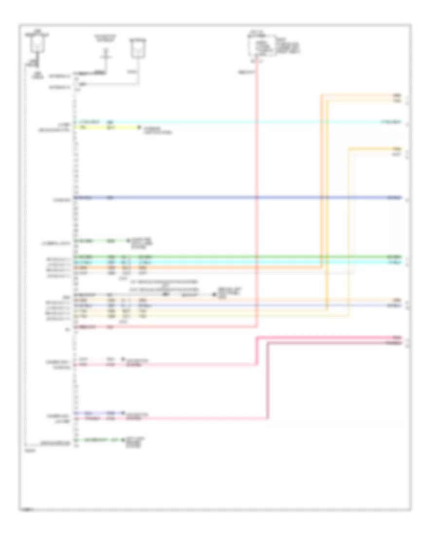
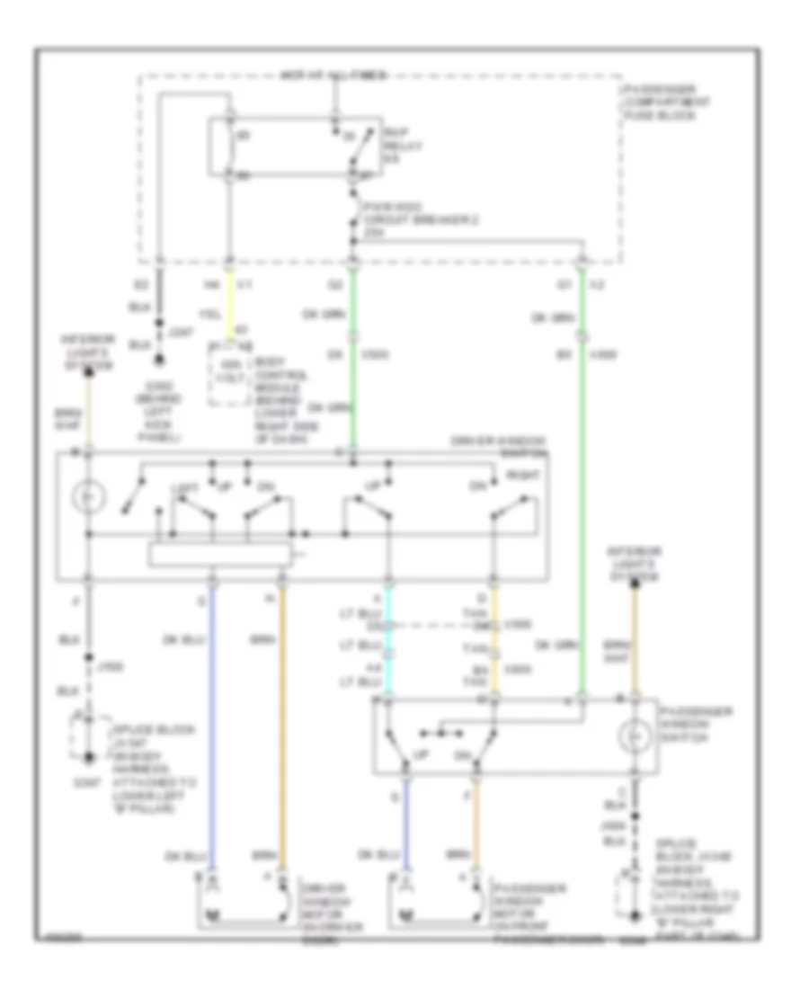
ANTI-THEFT
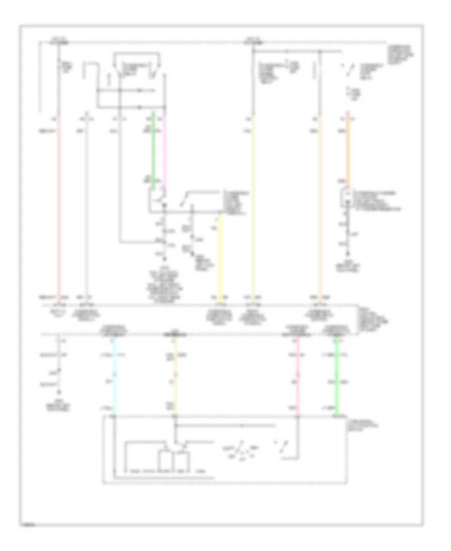
Forced Entry Wiring Diagram (1 of 2) for GMC RV Cutaway G2013 3500
 https://portal-diagnostov.com/license.html
Automotive Electricians Portal FZCO
Automotive Electricians Portal FZCO
https://portal-diagnostov.com/license.html
https://portal-diagnostov.com/license.html
Automotive Electricians Portal FZCO
Automotive Electricians Portal FZCO
List of elements for Forced Entry Wiring Diagram (1 of 2) for GMC RV Cutaway G2013 3500:
- Body control module (bcm) (behind lower right side of dash)
- Body fuse block (under left front seat)
- Cargo door unlock relay
- Cargo dr unlck fuse 33 15a
- Chime module (behind left center of dash)
- Closed sw sig
- Computer data lines system
- Door lock relay
- Door unlock relay
- Driv door lock rly
- Driv door lock sig
- Driv door unlock sig
- Driver door unlatch relay
- Dvr dr unlck fuse 36 15a
- Frt dr lck fuse 31 15a
- Frt pass dr unlck fuse 34 15a
- G100 (on left front of engine compt)
- G302 (behind left kick panel)
- G347
- G348
- Ground
- Hood ajar switch (w/ remote engine start)
- Hot at all times
- J100
- J247
- J248
- Left rear side door jam switch (w/ hinged door) (at left "b" pillar)
- Lf door ajar sw
- Lf door open sw
- Liftgate ajar sw sig
- Lo spd
- Lo spd gmlan serial data x3
- Lr door open sw
- Mega fuse 125a
- Nca
- Pass door lock sw
- Radio
- Rear dr lck fuse 32 15a
- Rear open sw
- Rear pass dr unlck fuse 35 15a
- Remote control door lock receiver (rcdlr) (behind center of dash)
- Rf door ajar sw
- Rf door open sw
- Rfa/tpm fuse 21 10a
- Right rear side door jam switch (w/ cargo passenger) (at right "b" pillar)
- Rr door open sw
- Serial data
- Serial data bus +
- Serial data bus -
- Splice block jx347 (in body harness, attached to lower left "b" pillar)
- Splice block jx348 (in body harness, attached to lower right "b" pillar part of g348)
- Sw sig
- Tan
- Underhood fuse block (on left side of engine compt)
- W/ commercial tradesman
- W/ hinged door
- W/o commercial tradesman
- X150
- X318
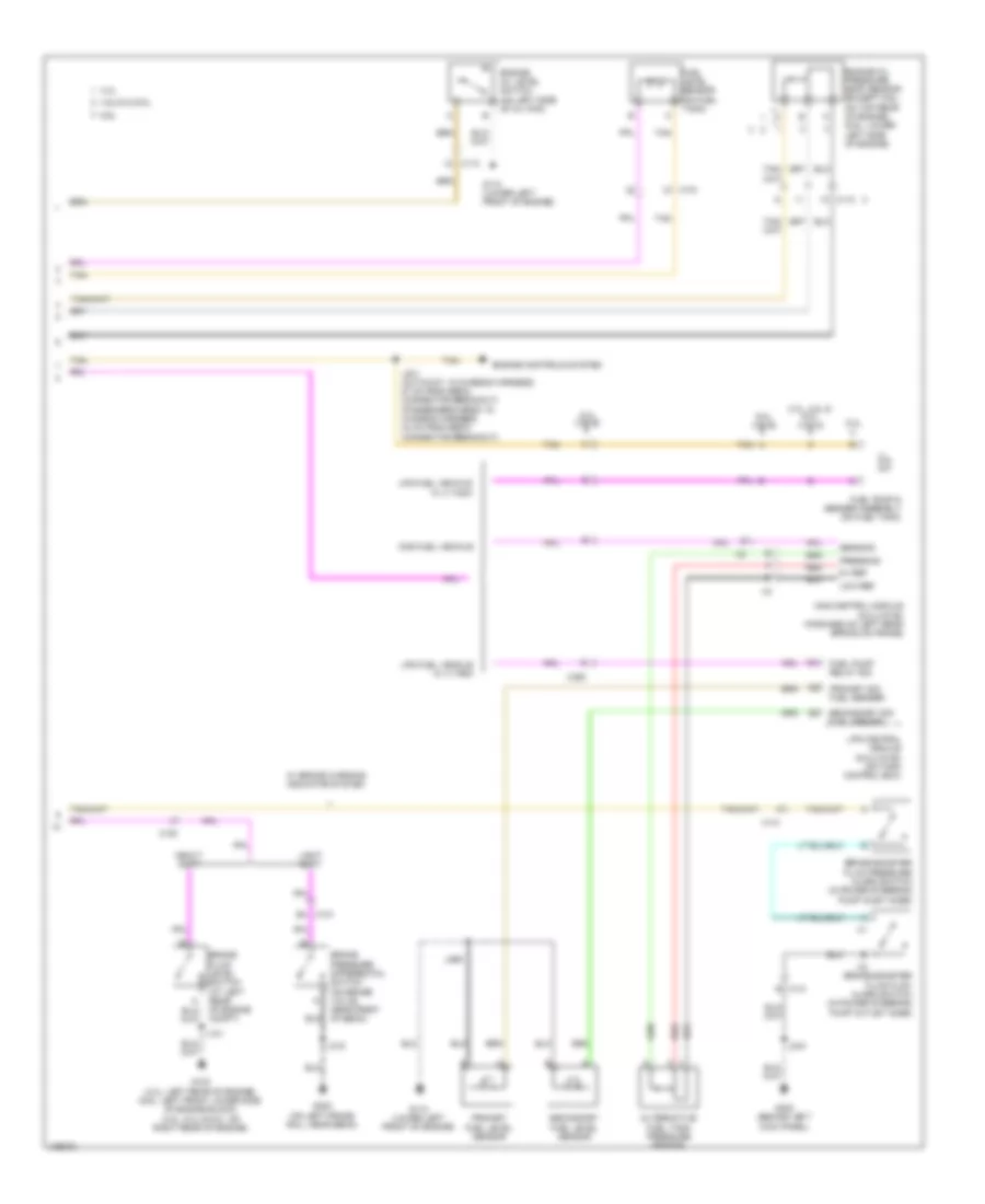
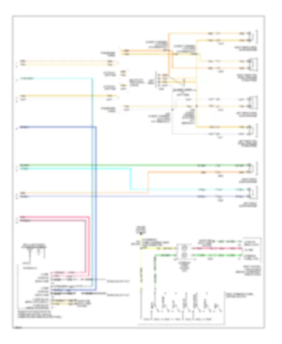
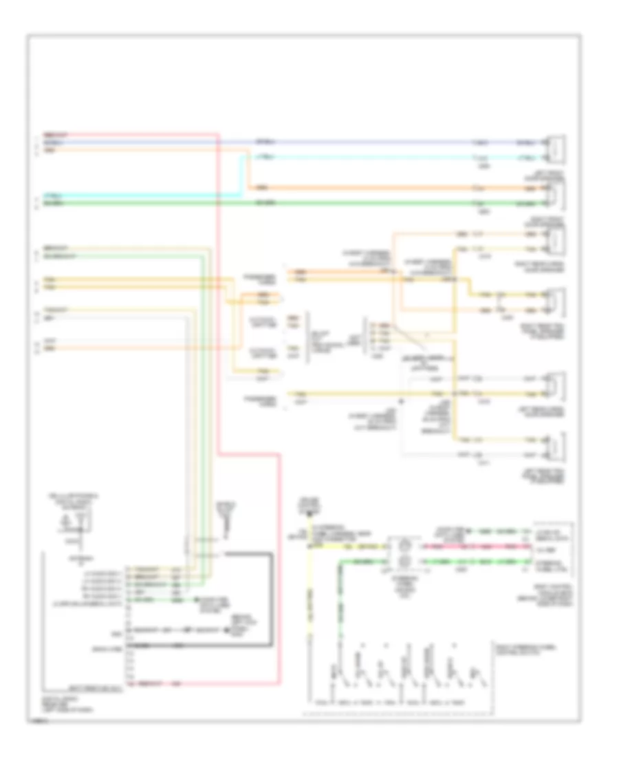
Forced Entry Wiring Diagram (2 of 2) for GMC RV Cutaway G2013 3500
List of elements for Forced Entry Wiring Diagram (2 of 2) for GMC RV Cutaway G2013 3500:
- (in body harness, 40 cm from x306 breakout)
- (in body harness, near front passenger seat, 20 cm from x306)
- (in right front door harness, 5 cm from passenger outside rearview mirror breakout)
- A11
- B11
- C10
- C11
- C12
- Cargo door latch assembly (w/ cargo/passenger) (in right rear cargo door)
- Cargo/ passenger
- Computer data lines system
- Cutaway
- Driver door latch assembly (at rear of driver door)
- Driver door lock switch
- Driver information center (dic) display
- G347
- G348
- G401 (on top of right "d" pillar)
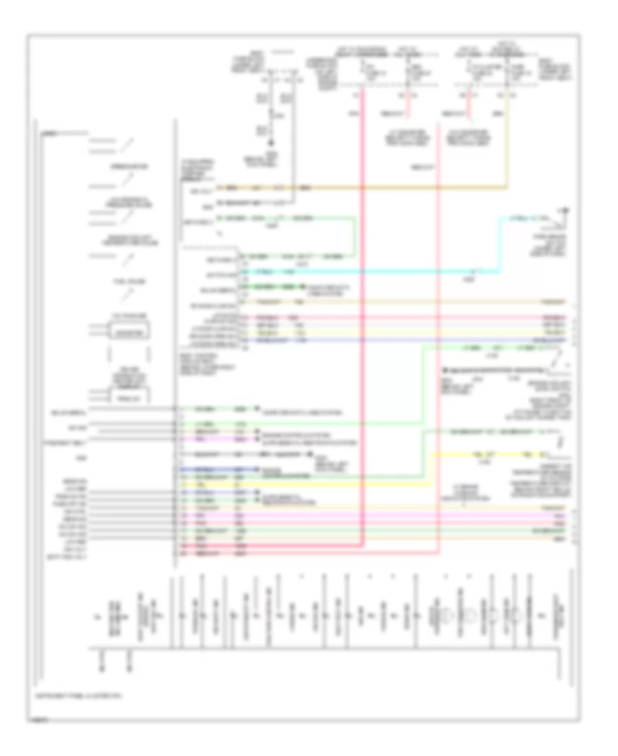
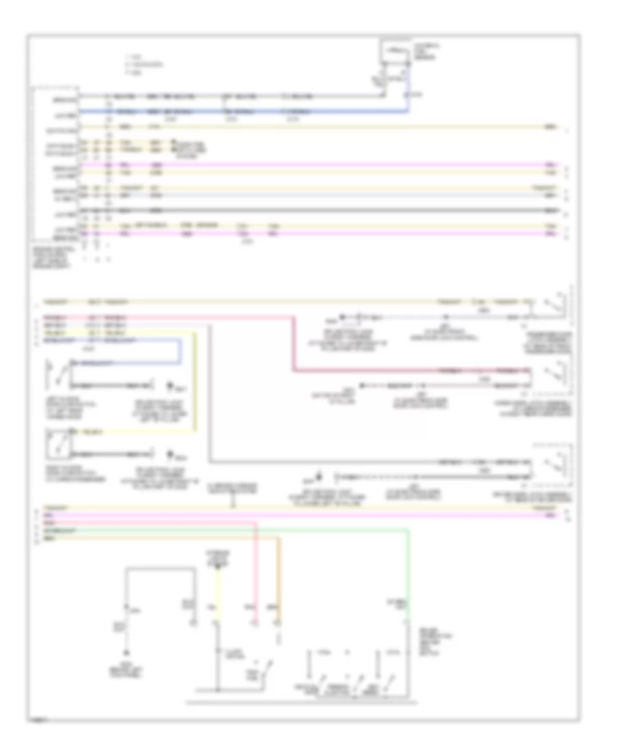
- Instrument cluster (ipc)
- J322
- J323
- J501 (w/ electronic side door lock control)
- J601 (w/ electronic side door lock control)
- J901 (w/ electronic side door lock control) (in rear cargo door harness, 35 cm from x902)
- Left body sliding door jamb contact plate (at left "b" pillar)
- Left rear side door lock actuator (w/ left rear hinged side door & rear sliding side door) (rear of left door)
- Logic
- Low spd gmlan serial data
- Passenger door latch assembly (at rear of front passenger door)
- Passenger door lock switch
- Rear cargo door lock switch
- Right body sliding door jamb contact plate (at right "b" pillar)
- Right rear side door lock actuator (w/ rear hinged side door & rear sliding side door) (hinged: at left side of right door)
- Security indicator
- Splice block jx347 (in body harness, attached to lower left "b" pillar)
- Splice block jx348 (in body harness, attached to lower right "b" pillar part of g348)
- Tan
- W/ hinged door
- W/ hinged doors
- W/ sliding doors
- X318
- X400
- X500
- X600
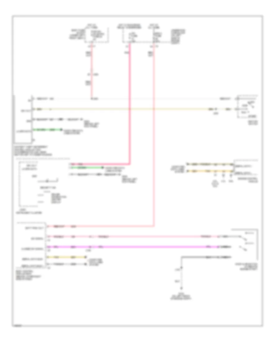
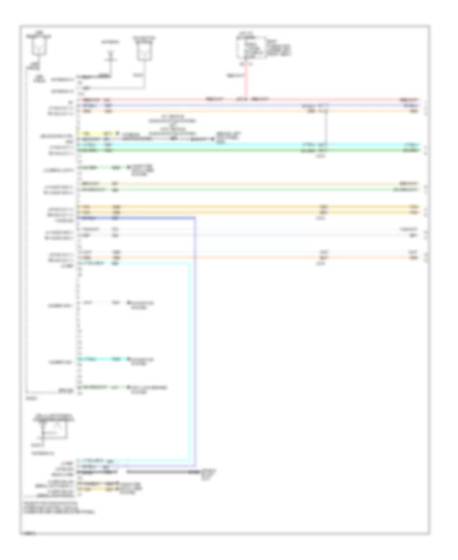
Pass-Key Wiring Diagram for GMC RV Cutaway G2013 3500
List of elements for Pass-Key Wiring Diagram for GMC RV Cutaway G2013 3500:
- 4.3l
- 4.8l, 5.3l & 6.0l
- 6.6l
- Acc
- Batt pos volt
- Bcm 3 fuse 10a
- Body control module (bcm) (behind lower right side of dash)
- Body fuse block (under left front seat)
- Closed sw signal
- Computer data lines system
- Content theft deterrent control module (tdm) (in steering column, near ignition key cylinder housing)
- Driver information center display
- Engine control module
- G100 (on left front of engine compt)
- G302 (behind left kick panel)
- Gnd
- Hood ajar switch (w/ remote engine start)
- Hot at all times
- Hot w/ run/crank relay 15 energized
- Ign sw (dlis)/pk3 fuse 22 2a
- Ign volt
- Ignition switch
- Instrument cluster
- Ipc fuse 10a
- J100
- J202
- J203
- J205
- J244
- Lo spd data
- Lock
- Logic
- Nca
- Pnk
- Run
- Security ind
- Serial data +
- Serial data -
- Serial data bus +
- Serial data bus -
- Start
- Sw signal
- Tan
- Underhood fuse block (on left side of engine compt)
- X1 h7
- X150
- X200 b1
- X3 a4
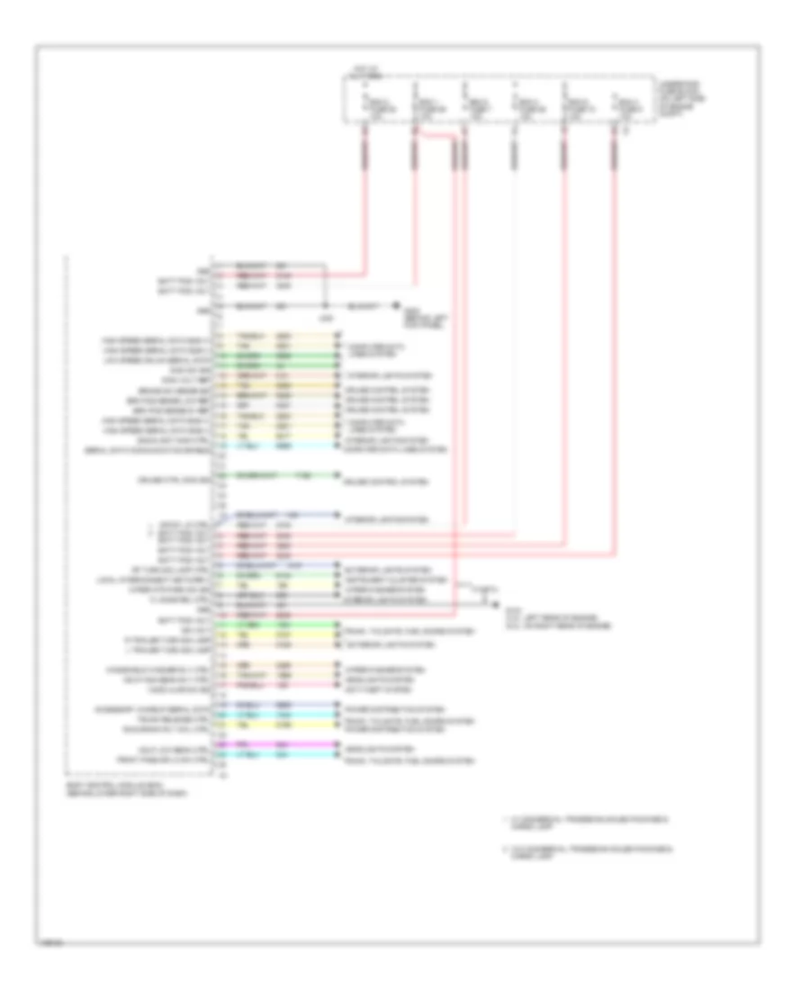
BODY CONTROL MODULES
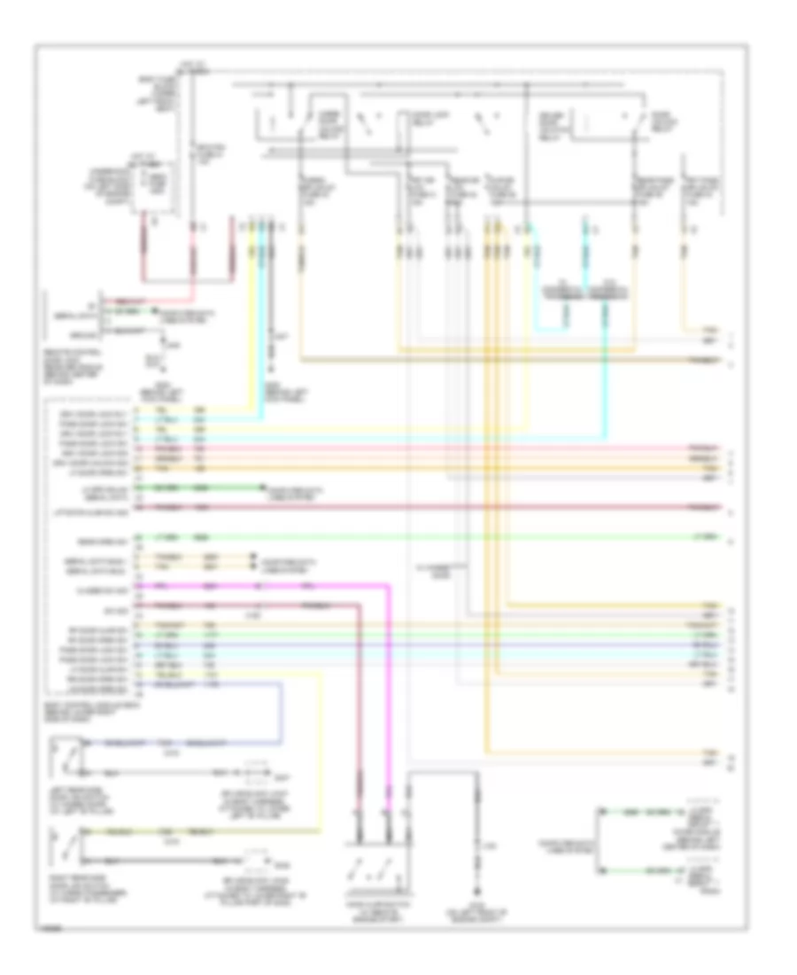
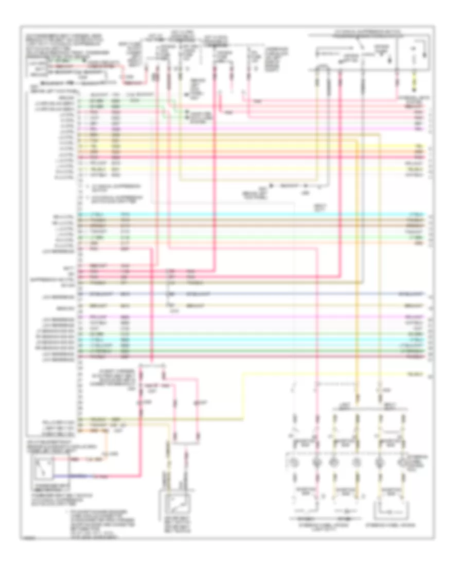
Body Control Modules Wiring Diagram (1 of 2) for GMC RV Cutaway G2013 3500
List of elements for Body Control Modules Wiring Diagram (1 of 2) for GMC RV Cutaway G2013 3500:
- 4.3l/5.3l
- Accessory wakeup serial data
- Anti-theft system
- Backlight dimm ctrl
- Batt pos volt
- Bcm 1 fuse 59 10a
- Bcm 2 fuse 58 10a
- Bcm 3 fuse 26 10a
- Bcm 4 fuse 9 10a
- Bcm 5 fuse 7 10a
- Bcm 6 fuse 72 10a
- Body control module (bcm) (behind lower right side of dash)
- Brake sw sense sig
- Brk pos sense 5v ref
- Brk pos sense low ref
- Cargo lamp
- Computer data lines system
- Crtsy lp ctrl batt pos volt batt pos volt
- Cruise control system
- Cruise ctrl dimm sig
- Dimm sw sig
- Dimm volt ref
- Exterior lights system
- Fl dome rel ctrl
- Front pass dr lk sw ctrl
- G103 (4.3l: left rear of engine) (5.3l: on right rear of engine)
- G302 (behind left kick panel)
- Gnd
- Hdlp high beam rly ctrl
- Hdlp low beam ctrl
- Headlights system
- High speed serial data bus (+)
- High speed serial data bus (-)
- Hood ajar sw sig
- Hot at all times
- Ign volt
- Instrument cluster system
- Interior lights system
- J248
- L trailer turn sig lamp
- Local interconnect network 3
- Low speed gmlan serial data
- Power distribution system
- R trailer turn sig lamp
- Rf turn sig lamp ctrl
- Run/crank rly coil ctrl
- Serial data communication enable
- Tan
- Trunk release ctrl
- Trunk, tailgate, fuel doors system
- Underhood fuse block (on left side of engine compt)
- W/ commercial tradesman sales package &
- W/o commercial tradesman sales package &
- Windshield washer rly ctrl
- Wiper mtr park sw sig
- Wiper/washer system
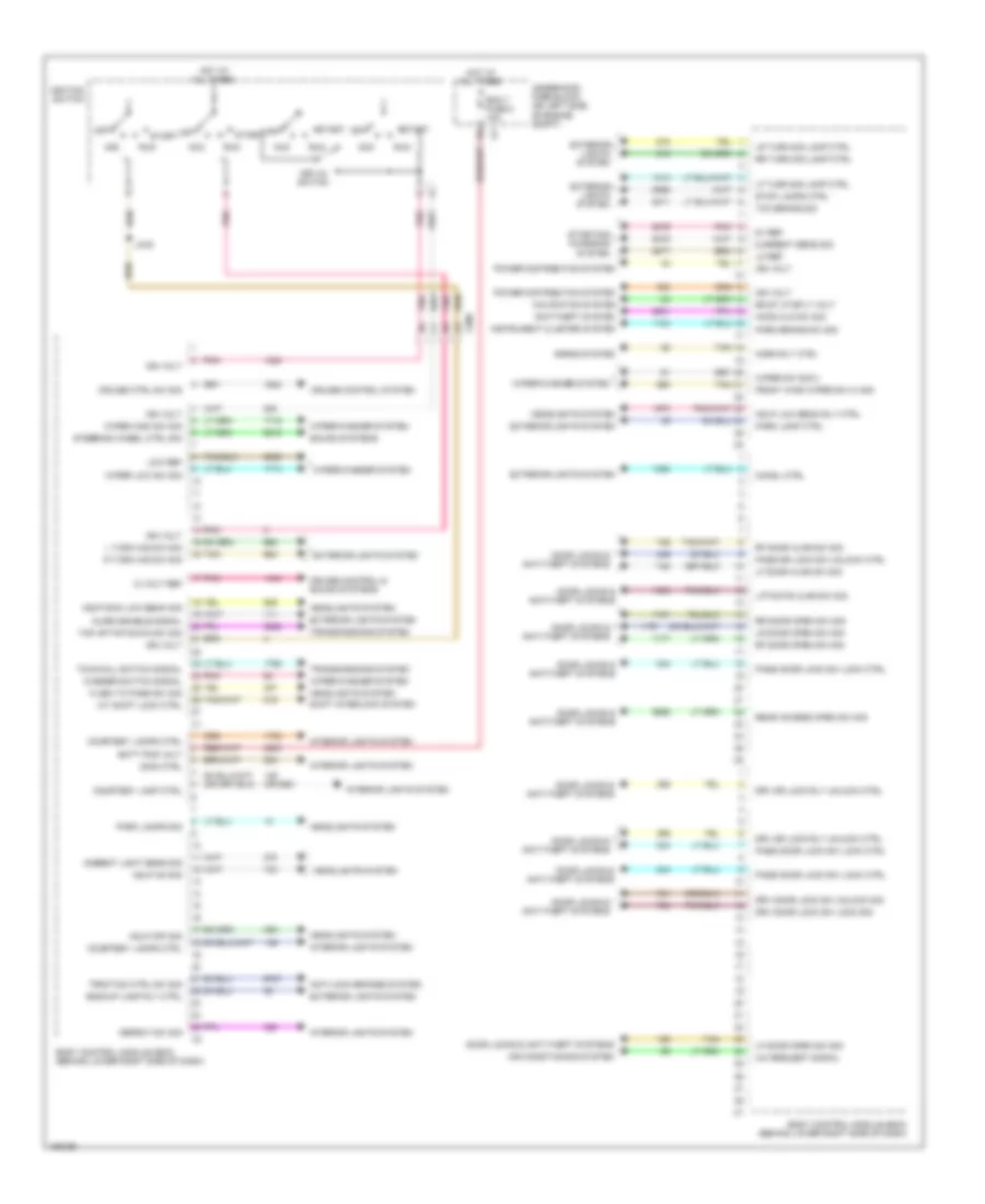
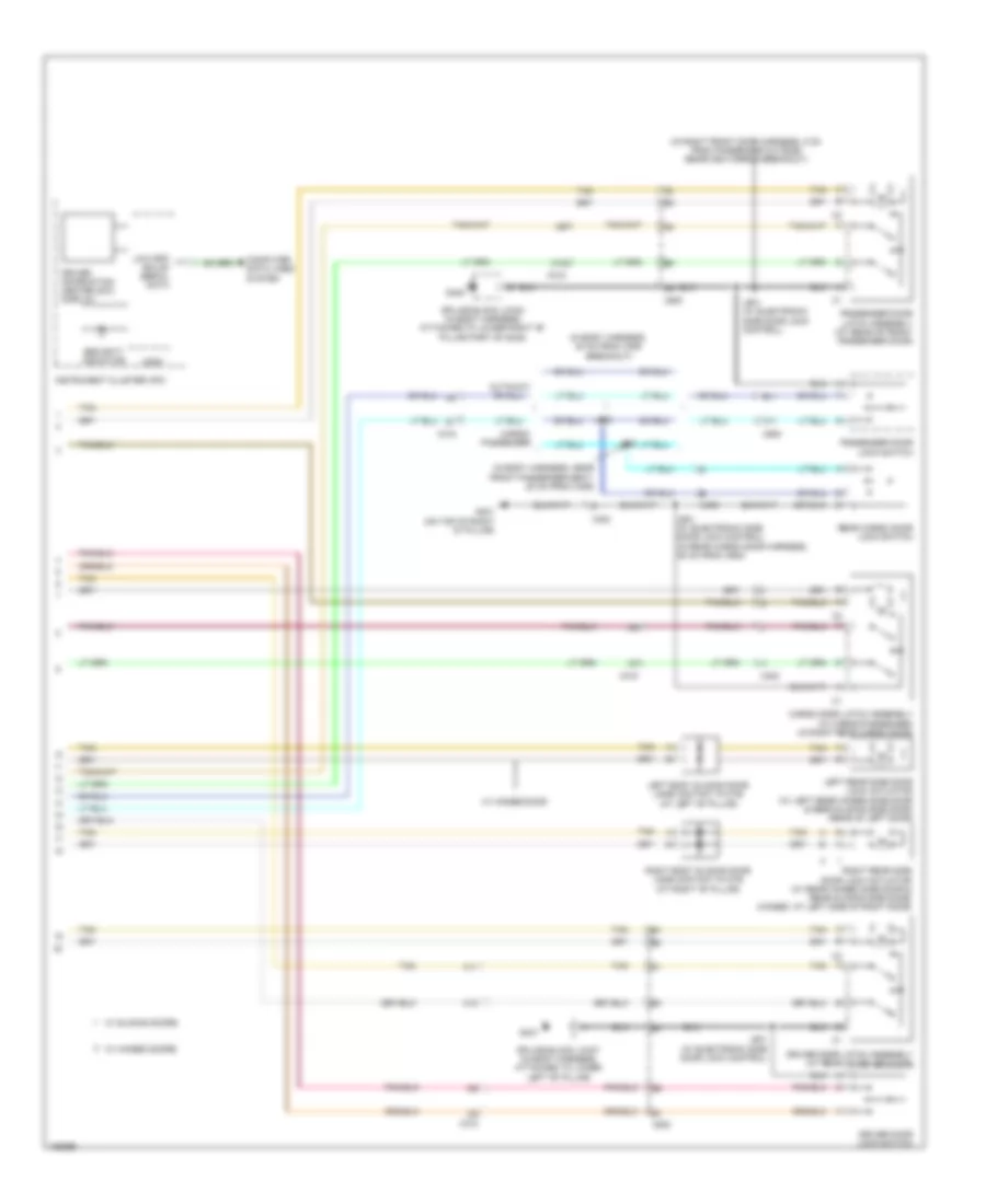
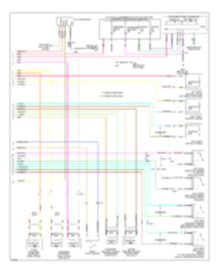
Body Control Modules Wiring Diagram (2 of 2) for GMC RV Cutaway G2013 3500
List of elements for Body Control Modules Wiring Diagram (2 of 2) for GMC RV Cutaway G2013 3500:
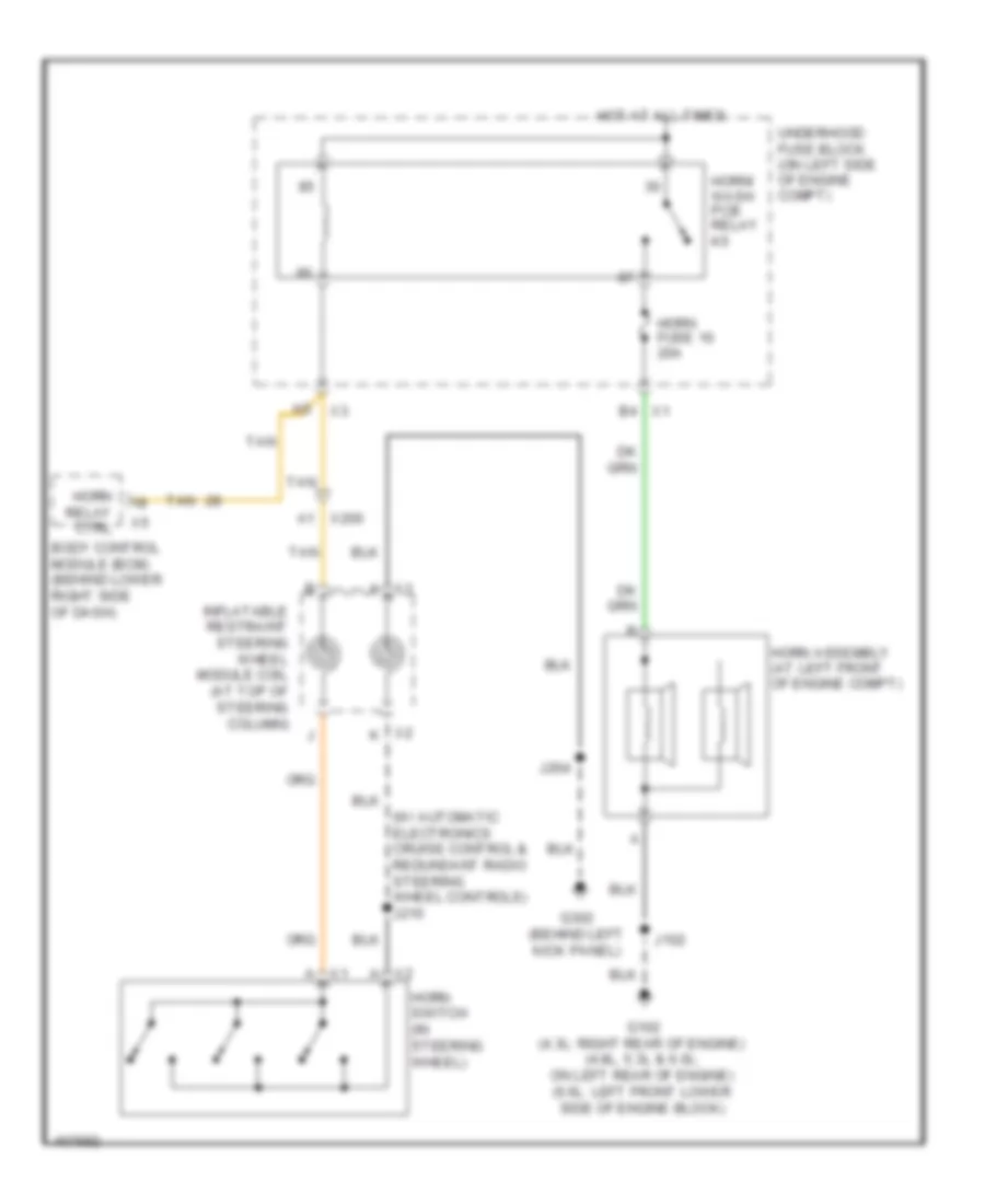
- (or 690)
- 12 volt ref
- 5v ref
- A/c request signal
- A/t shift lock ctrl
- Acc
- Air conditioning system
- Alarm enable signal
- Ambient light sens sig
- Anti-lock brakes system
- Anti-theft system
- Backup lamp rly ctrl
- Batt pos volt
- Bcm 7 fuse 8 10a
- Bkup lp sply volt
- Body control module (bcm) (behind lower right side of dash)
- Chmsl ctrl
- Courtesy lamp ctrl
- Courtesy lamps ctrl
- Cruise control & sound systems
- Cruise control system
- Cruise ctrl sw sig
- Current sens sig
- Defeat sw sig
- Dimm ctrl
- Door locks & anti-theft systems
- Drv door lock sw lock sig
- Drv door lock sw unlock sig
- Drv dr lock rly unlock ctrl
- Exterior lights system
- Flash to pass sw sig
- Front wind wiper sw hi sig
- Hdlp dimm low beam sig
- Hdlp low beam rly ctrl
- Hdlp off sig
- Hdlp on sig
- Headlights system
- Hood cld sw sig
- Horn rly ctrl
- Horns system
- Hot at all times
- Ign volt
- Ignition switch
- Instrument cluster system
- Interior lights system
- J205
- Key-in switch
- L turn haz sw sig
- Lf door ajar sw sig
- Lf door open sw sig
- Lf turn sig lamp ctrl
- Liftgate ajar sw sig
- Lo ref
- Low ref
- Lr door open sw sig
- Lr turn sig lamp ctrl
- Navigation system
- Off
- Park brake sw sig
- Park lamp ctrl
- Park lamps sig
- Pass door lock sw lock ctrl
- Pass dr lock sw unlock ctrl
- Pnk
- Power distribution system
- R turn haz sw sig
- Rear access open sw sig
- Rf door ajar sw sig
- Rf door open sw sig
- Rr door open sw sig
- Rr turn sig lamp ctrl
- Run
- Shift interlock system
- Sound systems
- Start
- Starting/ charging system
- Steering wheel ctrl sig
- Stop lamps ctrl
- Tan
- Tap up/tap down sw sig
- Tcc brake sig
- Tow/haul switch signal
- Traction ctrl sw sig
- Transmissions system
- Underhood fuse block (on left side of engine compt)
- Washer switch signal
- Wiper high sw sig
- Wiper low sw sig
- Wiper sw sig 2
- Wiper/washer system
- X200
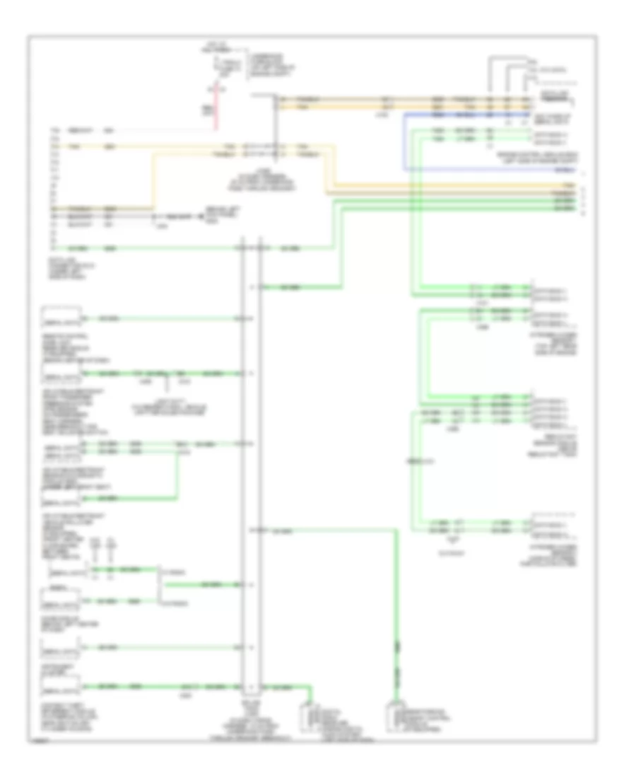
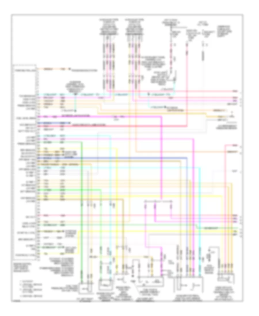
COMPUTER DATA LINES
Computer Data Lines Wiring Diagram (1 of 2) for GMC RV Cutaway G2013 3500
List of elements for Computer Data Lines Wiring Diagram (1 of 2) for GMC RV Cutaway G2013 3500:
- (behind left kick panel) g302
- 4.3l
- 4.8l, 5.3l & 6.0l
- 6.6l
- Acc wake up serial data
- B10
- Chime module (behind left center of dash)
- Content theft deterrent module (in steering column, near ignition key cylinder housing)
- Cutaway
- Data bus (+)
- Data bus (-)
- Data link connector (dlc) (under left side of dash)
- Data link resistor
- Data serial
- Digital radio receiver (s-band digital audio system) (left side of dash)
- E13
- Engine control module (ecm) (left side of engine compt)
- Hot at all times
- Inflatable restraint front passenger presence system (pps) sensor (on passenger's seat harness, near breakout for seat adjuster switch)
- Inflatable restraint sensing & diagnostic module (sdm) (under left front seat)
- Inflatable restraint vehicle rollover sensor (if equipped) (front center floor board, between front seats)
- Instrument cluster
- J244
- Jx250 (in dash harness, 20 cm from underhood pass through grommet)
- Light duty w/o recreational vehicle, upfitter sales package
- Ltr/dlc fuse 73 20a
- Nitrogen oxides sensor 1 (top left rear side of engine)
- Nitrogen oxides sensor 2 (middle of diesel particulate filter)
- Radio
- Rear parking assist control module (if equipped)
- Reductant sensor module (above reductant tank)
- Remote control door lock receiver (rcdlr) (if equipped) (behind center of dash)
- Serial data
- Splice pack jx200 (in dash wiring harness, 10 cm from underhood pass- through grommet breakout)
- Tan
- Underhood fuse block (on left side of engine compt)
- W/ radio
- W/ uys
- W/o radio
- W/o uys
- X100
- X101
- X115
- X200
- X3 g1
- X306
- X318
- X395
Computer Data Lines Wiring Diagram (2 of 2) for GMC RV Cutaway G2013 3500
List of elements for Computer Data Lines Wiring Diagram (2 of 2) for GMC RV Cutaway G2013 3500:
- (6.6l)
- (in engine harness, 15 cm from x101 breakout) j115
- (left rear of engine) (6.6l) glow plug control module (gpcm)
- 4.3l & 5.3l
- 4.8l & 6.0l
- 5.3l
- 6.6l
- Acc wake up serial data
- Automatic transmission (6 speed a/t)
- Body control module (bcm) (behind lower right side of dash)
- Brake control
- Comm
- Control solenoid value assembly
- Coolant heater (6.6l w/ fuel fired auxiliary heater) (attached to left inner frame rail, near fuel pump assembly)
- Data bus (+)
- Data bus (+) data bus (-) x2
- Data bus (-)
- Data bus (-) data bus (+)
- Data comm
- Data enable
- Electronic brake control module (ebcm) (on left frame rail, near center of vehicle)
- Enable
- Except
- Except 5.3l
- Except 6.6l
- Fuel pump flow control module (at rear of vehicle, attached to left rear frame rail)
- Ign
- J119 (w/ fuel fired auxiliary heater) (in chassis harness, 15 cm from coolant heater breakout)
- J319 (in chassis harness, 7 cm from ecbm breakout)
- Serial data
- Tan
- Transmission control module (tcm) (4 speed a/t) (left front corner of engine compt)
- Vehicle communication interface module (vcm) (below steering column)
- W/ active
- W/ active brake control
- W/ fuel fired auxiliary heater
- W/ vehicle communication system
- W/o active
- W/o active brake control
- W/o fuel fired auxiliary heater
- W/o vehicle communication system
- X100
- X101
- X101 d1
- X105
- X107
- X174
- X174 r
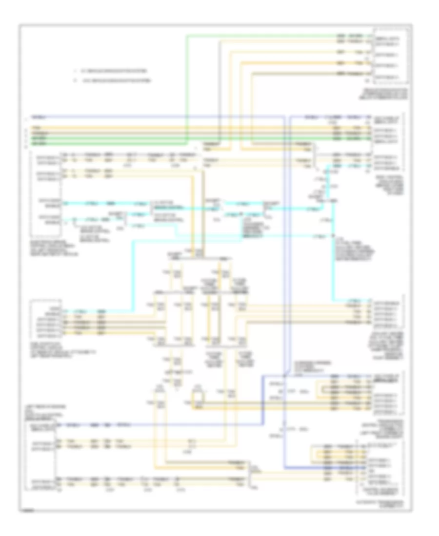
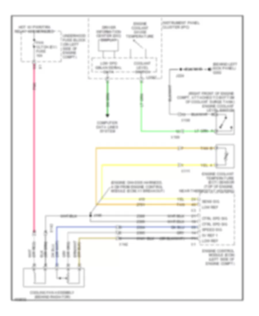
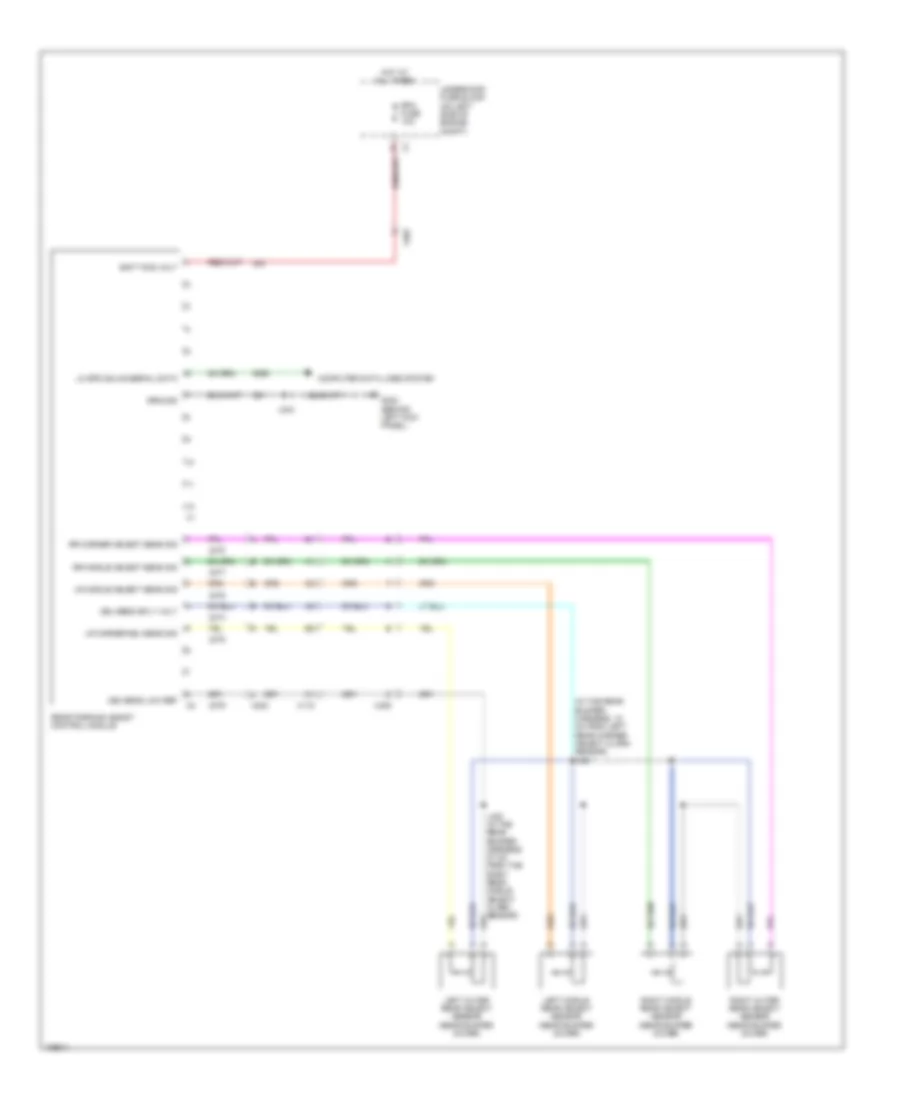
COOLING FAN
Cooling Fan Wiring Diagram for GMC RV Cutaway G2013 3500
List of elements for Cooling Fan Wiring Diagram for GMC RV Cutaway G2013 3500:
- (behind left kick panel) g302
- (engine chassis harness, 4 cm from engine control module (ecm) x1 breakout)
- (right front of engine compt, attached to bottom of coolant surge tank) engine coolant level switch
- 5v ref 1
- B tan
- Computer data lines system
- Coolant level switch
- Cooling fan assembly (behind radiator)
- Ctrl spd sig
- Driver information center (dic) display
- Engine control module (ecm) (left side of engine compt)
- Engine coolant gauge temperature
- Engine coolant temperature (ect) sensor (top of engine, near thermostat housing)
- Fan cltch (ev) fuse 10a
- Hot w/ pwr/trn relay 49 energized
- Instrument panel cluster (ipc)
- J145
- J224
- Logic
- Low ref
- Low spd gmlan serial data
- Pnk
- Sens sig
- Speed sig
- Tan
- Underhood fuse block (on left side of engine compt)
- X100
- X111
- X142
CRUISE CONTROL
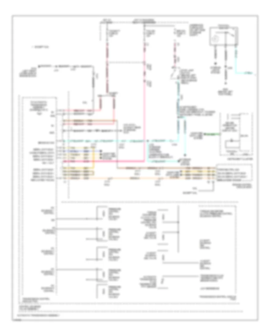
Cruise Control Wiring Diagram (1 of 2) for GMC RV Cutaway G2013 3500
List of elements for Cruise Control Wiring Diagram (1 of 2) for GMC RV Cutaway G2013 3500:
- (or pnk)
- 12v ref
- 4.3l
- 4.8l, 5.3l & 6.0l
- 5v ref 1
- 5v ref 2
- 6.6l
- A13
- A17
- Accelerator pedal position (app) sensor (under left side of dash)
- App sen 1 sig
- App sen 2 sig
- Batt +
- Bcm 2 fuse 10a
- Body control module (bcm) (behind lower right side of dash)
- Brake low ref
- Brake pedal position (bpp) sensor (top of brake pedal assembly)
- Brake sens sig
- Brake sig
- Computer data lines system
- Cruise control ind dimming sig
- Cruise control switch signal
- Cruise ind
- Ecm batt fuse 10a
- Engine control module (ecm)
- Except 4.3l
- G103 (4.3l: left rear of engine) (4.8l, 5.3l & 6.0l: on right rear of engine)
- G109 (lower right front of engine)
- G302 (behind left kick panel)
- Gmlan ser data
- Ground
- Hi spd gmlan ser data bus(+)
- Hi spd gmlan ser data bus(-)
- Hot at all times
- Hot w/ run/crank relay 15 energized
- Ign
- Inflatable restraint steering wheel module coil (at top of steering column)
- Instrument panel cluster (ipc)
- Ipc fuse 10a
- J101
- J160
- J244
- J248
- Logic
- Low ref
- Pnk
- Ser data bus(+)
- Ser data bus(-)
- Sply volt
- Tac motor ctrl 1
- Tac motor ctrl 2
- Tan
- Throttle body (except 6.6l) (4.8l, 5.3l & 6.0l: on left side of throttle body)
- Tp sens 1 sig
- Tp sens 2 sig
- Underhood fuse block (on left side of engine compt)
- X100
- X103
- X107
- X200
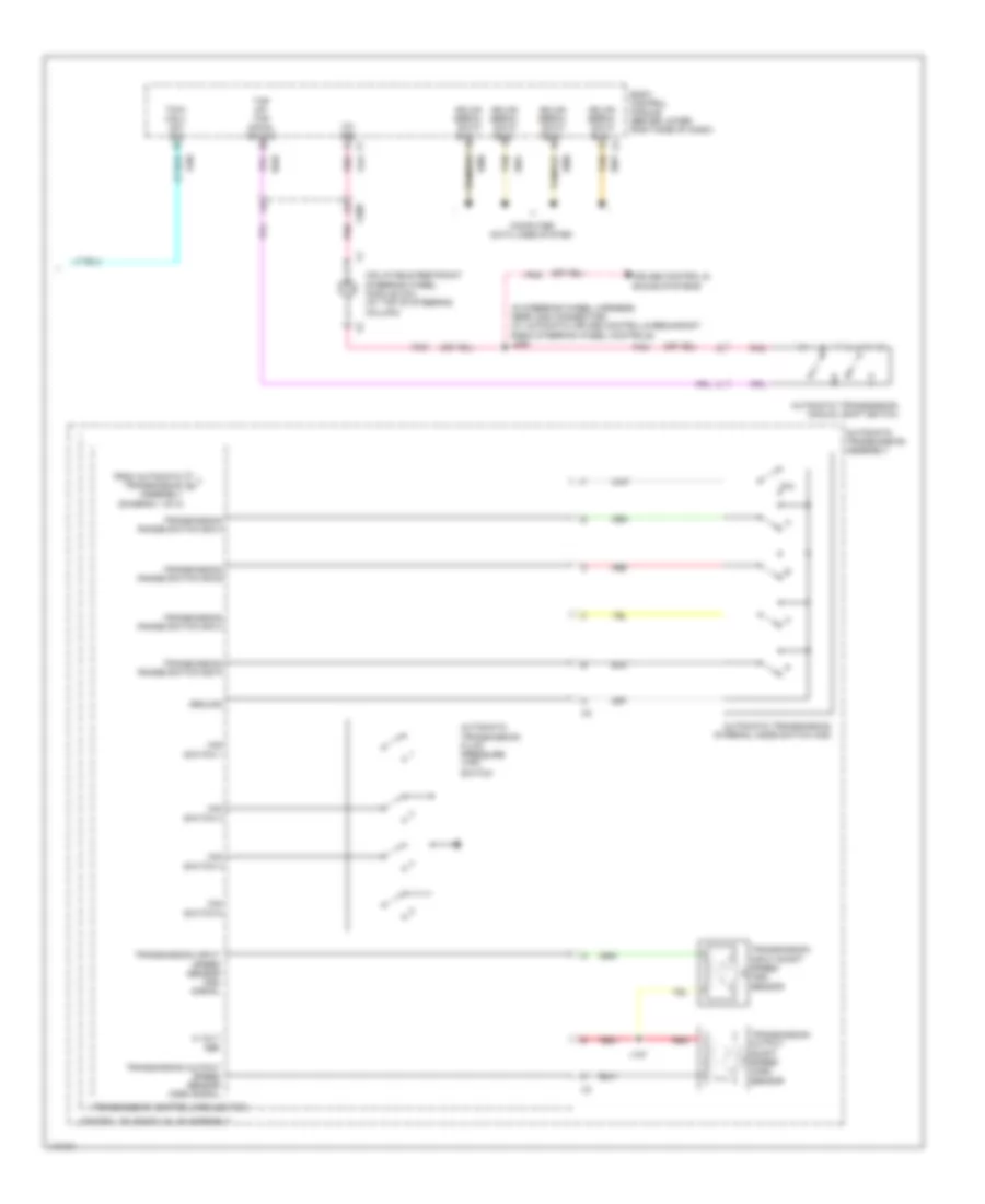
Cruise Control Wiring Diagram (2 of 2) for GMC RV Cutaway G2013 3500
List of elements for Cruise Control Wiring Diagram (2 of 2) for GMC RV Cutaway G2013 3500:
- (in steering wheel harness, near x200 connector)
- (or pnk)
- 6.6l
- Automatic transmission (6 speed a/t)
- Automatic transmission assembly
- Brake sig
- Cancel
- Computer data lines system
- Control solenoid valve assembly
- Cruise switch
- Data bus +
- Data bus -
- Exterior lights system
- Hot w/ run/crank relay 15 energized
- Iss sig
- J127
- J135
- J209
- Left steering wheel control switch
- Lo ref
- Pnk
- Red
- Res+
- Set-
- Sound systems
- Tan
- Trans fuse 15a
- Transmission control module (4 speed a/t)
- Transmission control module (tcm)
- Transmission input shaft speed (oss) sensor
- Transmission input shaft speed sensor
- Transmission output shaft speed (oss) sensor
- Transmission output shaft speed sensor (right rear side of transmission)
- Underhood fuse block (on left side of engine compt)
- Vss high sig
- Vss low sig
- W/ radio redundant steering wheel control
- W/o radio redundant steering wheel control
- X100
- X101
- X174
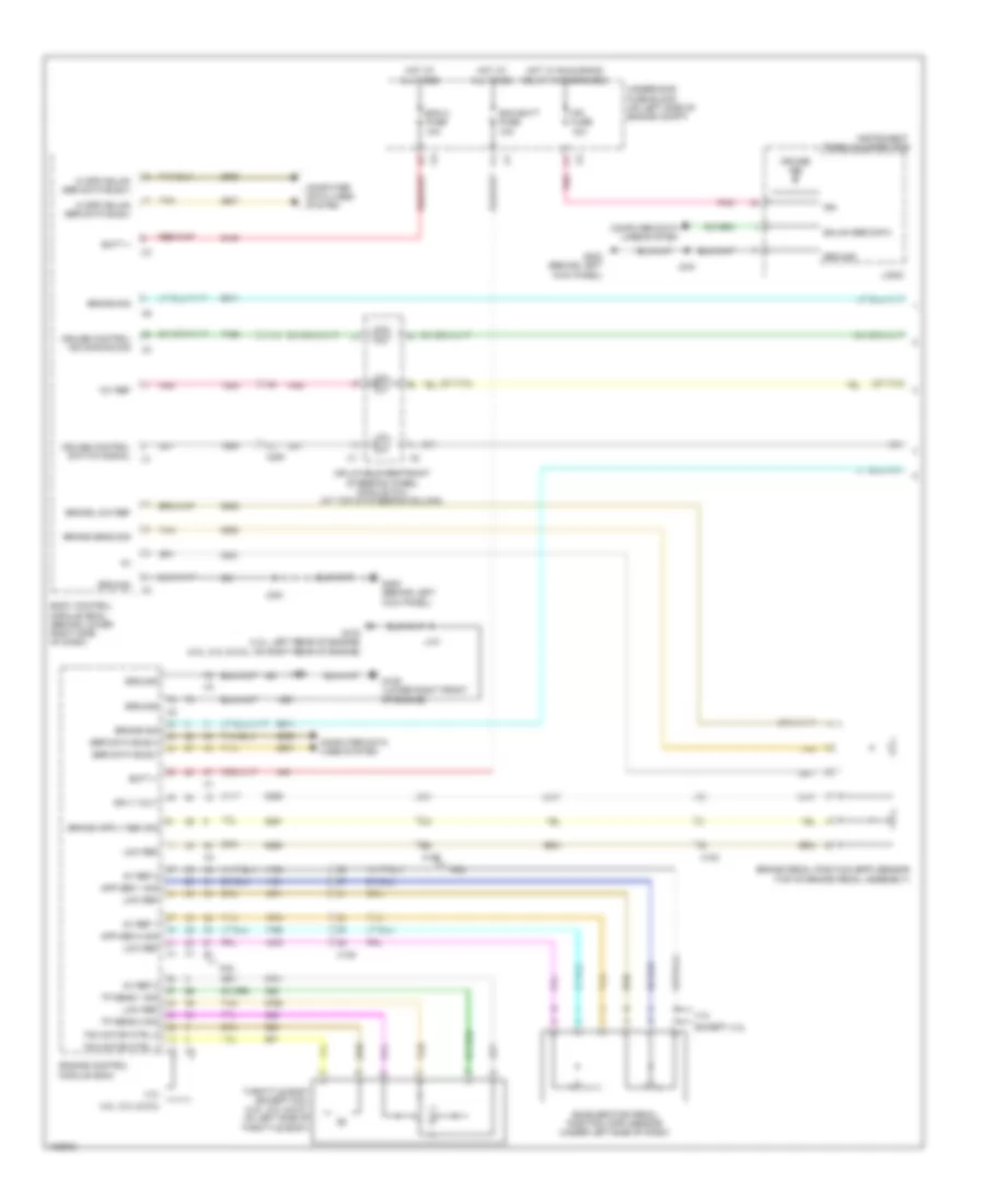
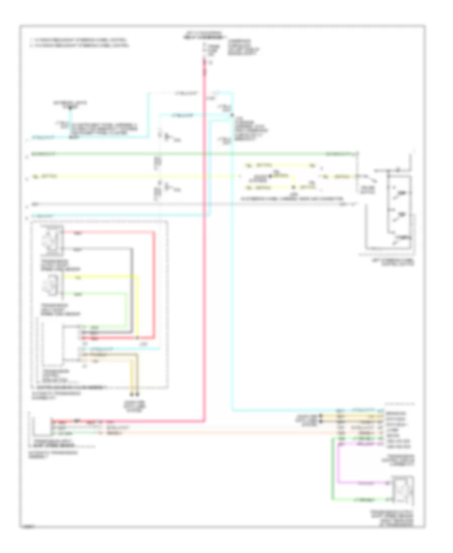
DEFOGGERS
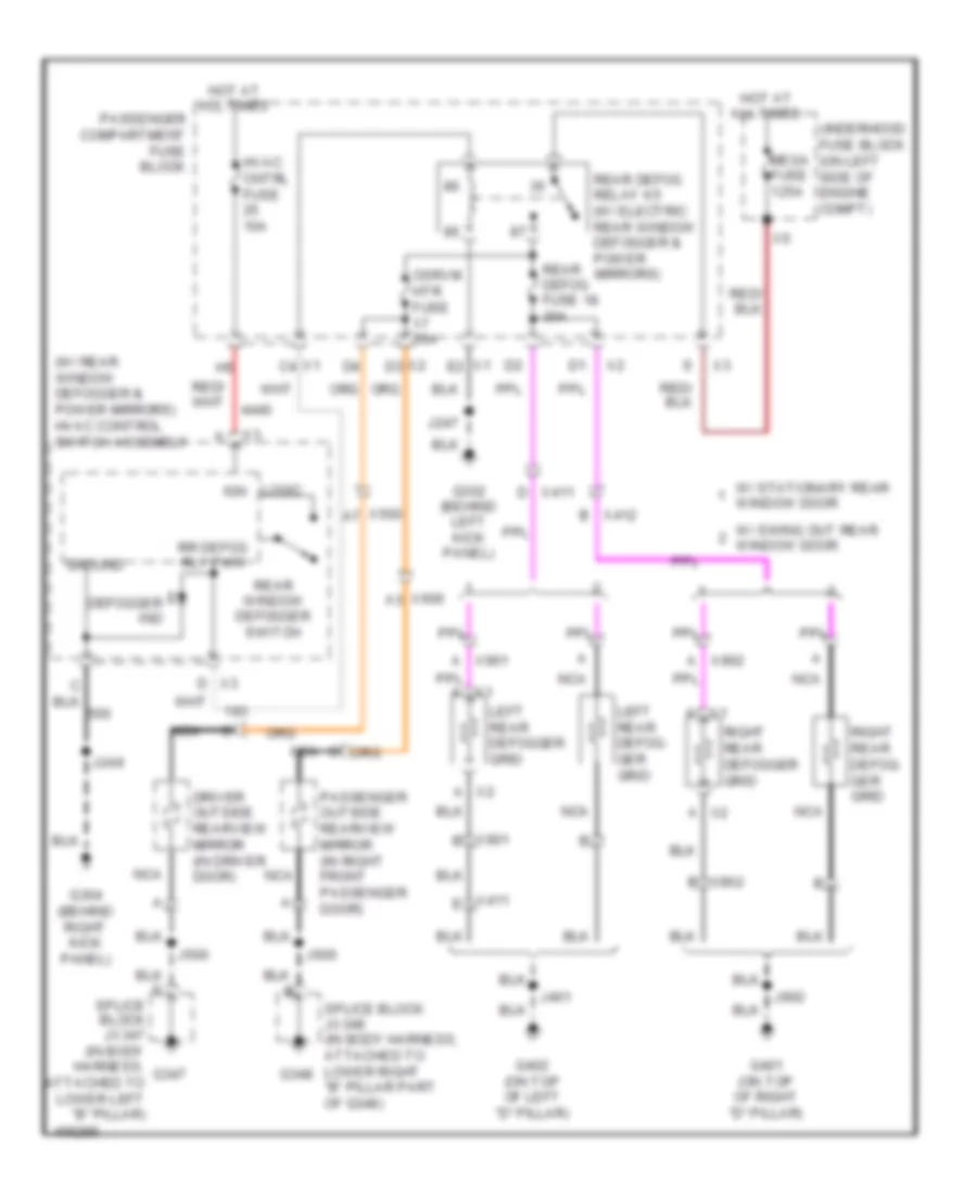
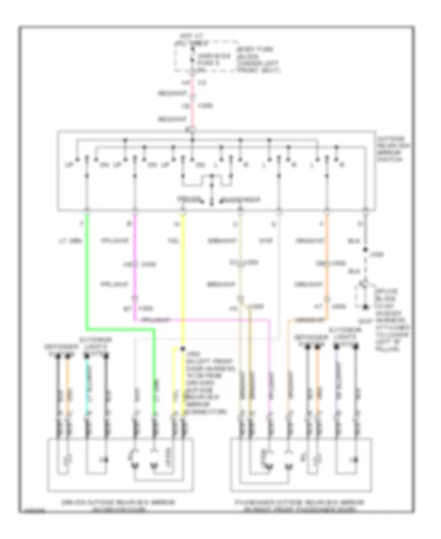
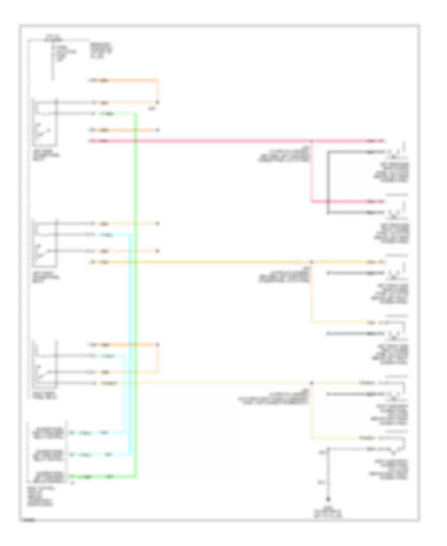
Defoggers Wiring Diagram for GMC RV Cutaway G2013 3500
List of elements for Defoggers Wiring Diagram for GMC RV Cutaway G2013 3500:
- (w/ rear window defogger & power mirrors) hvac control switch assembly
- A x2
- Defogger ind
- Driver outside rearview mirror (in driver door)
- G302 (behind left kick panel)
- G304 (behind right kick panel)
- G347
- G348
- G401 (on top of right "d" pillar)
- G402 (on top of left "d" pillar)
- Ground
- Hot at all times
- Hvac cntrl fuse 10a
- Ign
- J247
- J249
- J401
- J500
- J600
- J902
- Left rear defog- ger grid
- Left rear defogger grid
- Logic
- Mega fuse 125a
- Nca
- Osrvm htr fuse 20a
- Passenger compartment fuse block
- Passenger outside rearview mirror (in right front passenger door)
- Rear defog fuse 18 30a
- Rear defog relay k5 (w/ electric rear window defogger & power mirrors)
- Rear window defogger switch
- Right rear defog- ger grid
- Right rear defogger grid
- Rr defog rly pwr
- Splice block jx347 (in body harness, attached to lower left "b" pillar)
- Splice block jx348 (in body harness, attached to lower right "b" pillar part of g348)
- Underhood fuse block (on left side of engine compt)
- W/ stationary rear window door
- W/ swing out rear window door
- X1 a
- X1 c4
- X1 e2
- X2 a
- X3 d
- X411 d
- X411 e
- X412 b
- X500
- X600
- X901 a
- X901 b
- X902 a
- X902 b
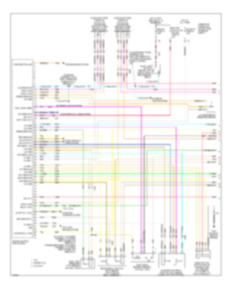
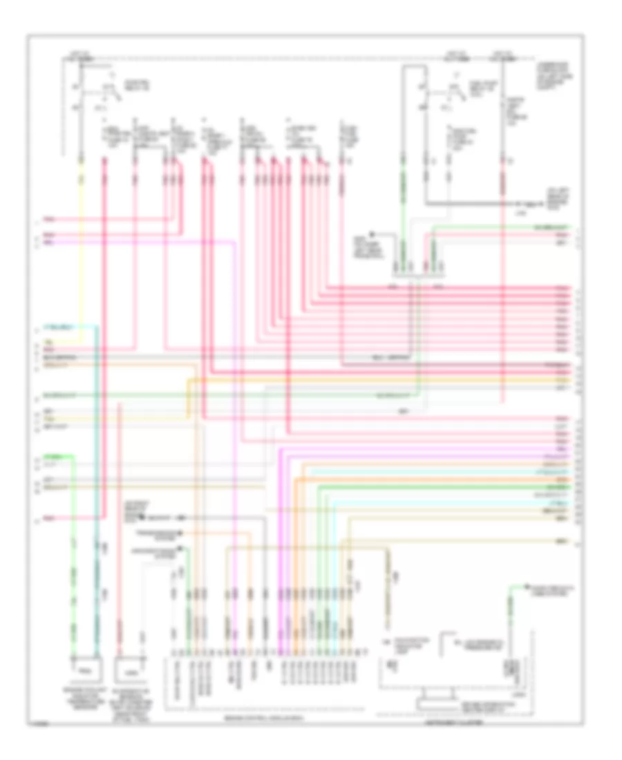
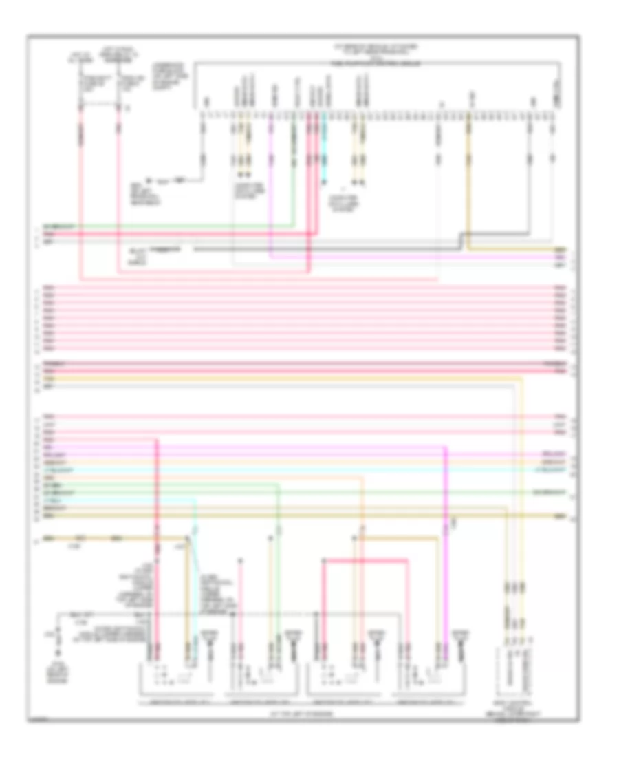
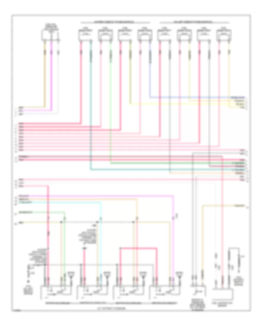
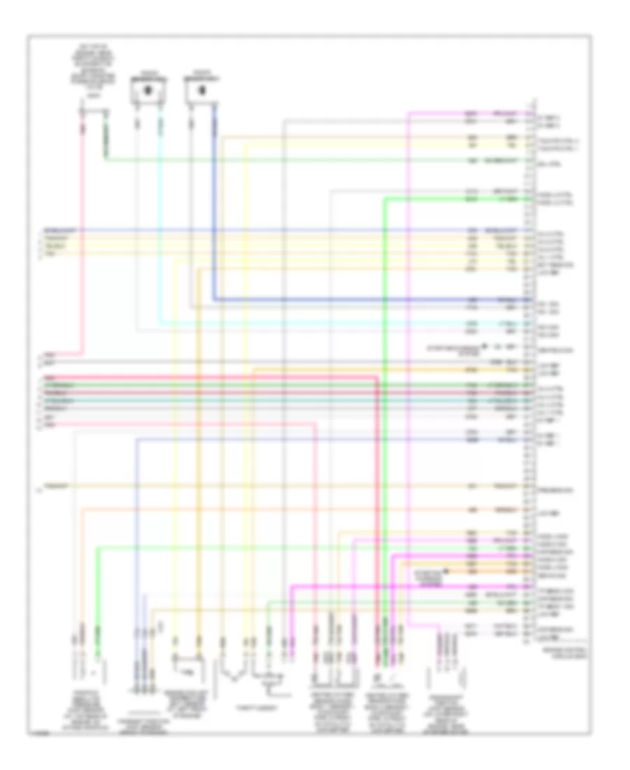
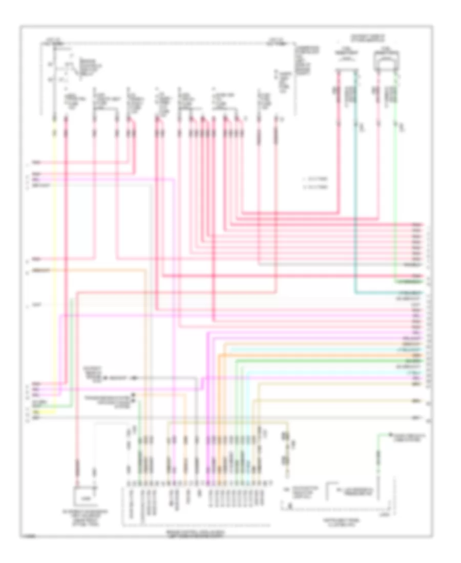
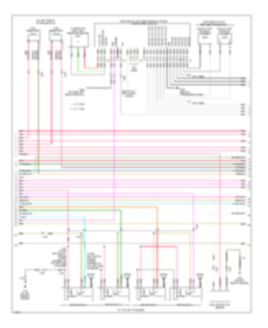
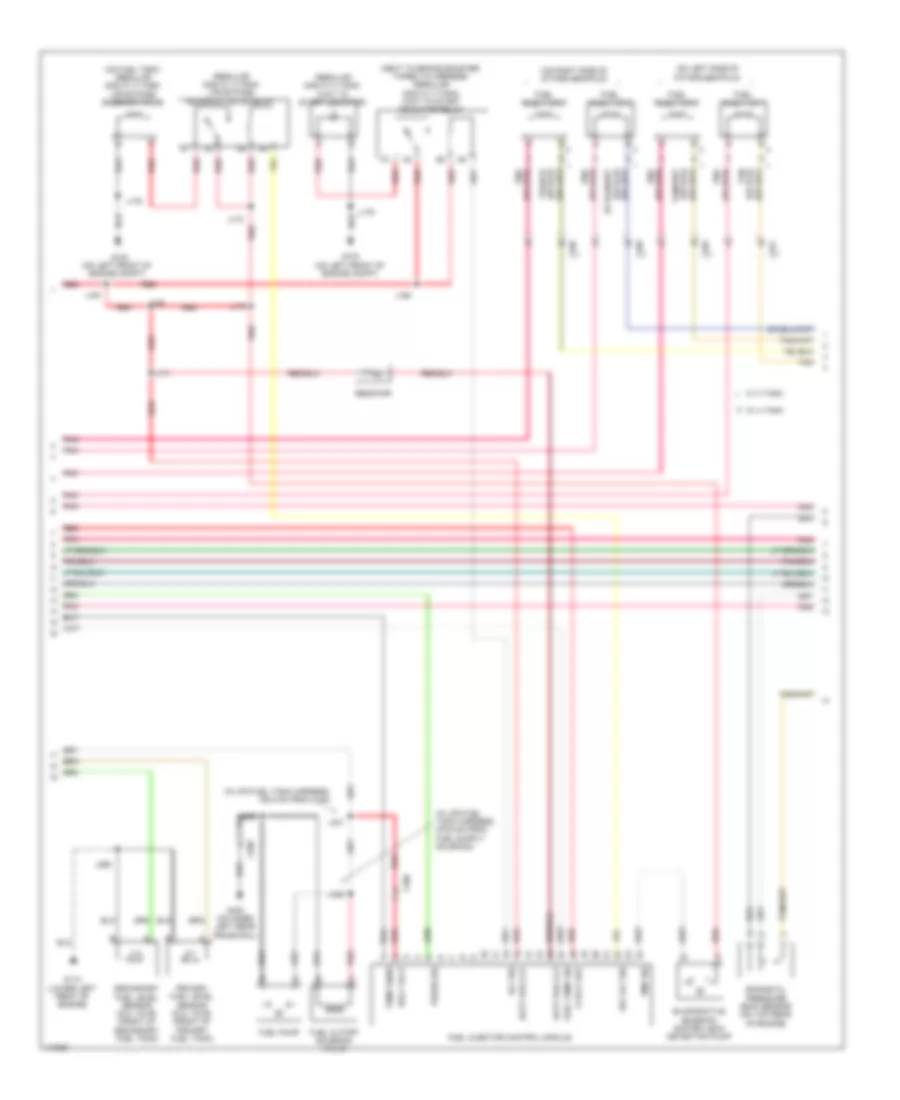
ENGINE PERFORMANCE
4.8L VIN A
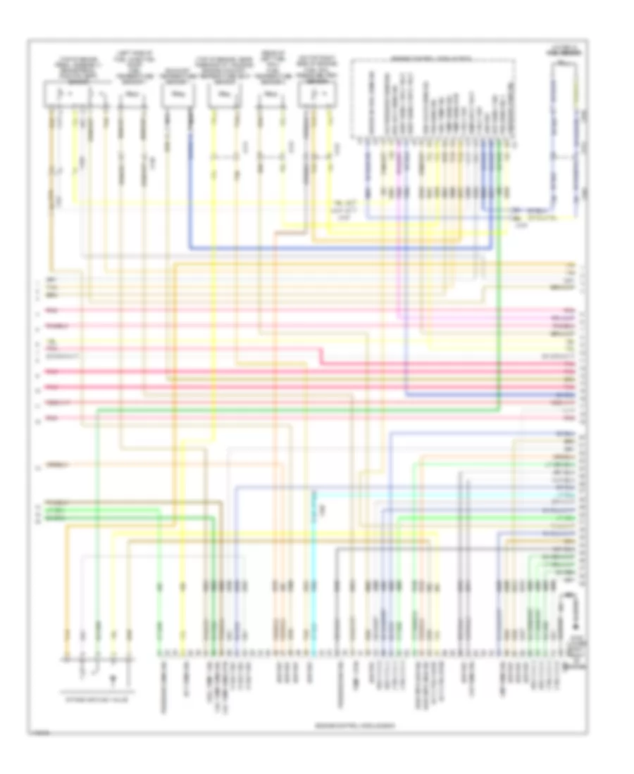
4.8L VIN A, Engine Performance Wiring Diagram (1 of 5) for GMC RV Cutaway G2013 3500
List of elements for 4.8L VIN A, Engine Performance Wiring Diagram (1 of 5) for GMC RV Cutaway G2013 3500:
- (5.3l)
- (cutaway: in chassis harness, 87 cm from ebcm connector breakout) (passenger/cargo: in chassis harness, 44 cm from ebcm connector breakout)
- (in engine harness, 16 cm from underhood fuse block x1 breakout) j123
- (in exhaust pipe, in back of catalytic converter) heated oxygen sensor (ho2s) bank 1 sensor 2
- (in exhaust pipe, in back of catalytic converter) heated oxygen sensor (ho2s) bank 2 sensor 2
- (in instrument panel harness, 5 cm from x200 breakout towards instrument panel cluster) j231
- (or pnk)
- 5.3l
- 5v ref 1
- 5v ref 2
- A/c refrigerant pressure sensor
- Acc ser data
- Accelerator pedal position (app) sensor (under left side of dash)
- Anti-lock brakes system
- App sens 1 sig
- App sens 2 sig
- Batt pos volt
- Brake pedal position (bpp) sensor (top of brake pedal assembly)
- Brk sens sig
- Brk sens sply
- Brk sw fuse 13 10a
- Comp sens sig
- Computer data lines system
- Cutaway
- Ecm batt fuse 19 10a
- Ecm ign/ glow plug mdl ign fuse 30 15a
- Ect sens sig
- Engine control module (ecm)
- Except 5.3l
- Exterior lights system
- Fuel level sens
- Fuel pump & sender assembly (on fuel tank)
- Fuel tank pressure (ftp) sensor (on fuel tank)
- G103 (on right rear of engine)
- Gmlan data+
- Gmlan data-
- Ho2s hi sig
- Ho2s lo sig
- Hot at all times
- Hot w/ run/ crnk relay 15 energized
- Iat sens sig
- Ign volt
- J101
- J301
- Low ref
- Maf sens sig
- Mass air flow (maf)/intake air temperature (iat) sensor (attached to air intake duct)
- Park/neutral sig
- Pnk
- Press sens sig
- Pwrtrn rly ctrl
- Relay ctrl
- Start rly ctrl
- Starting/ charging system
- Stop lamp switch (behind left side of dash, above brake pedal)
- Tan
- Tcc brake sig
- Transmissions system
- Underhood fuse block (on left side of engine compt)
- Vss
- X100
- X101
- X103
- X128
- X221
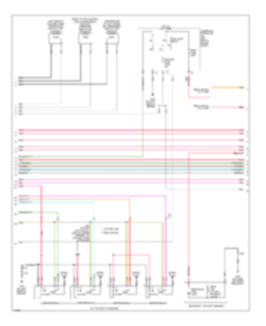
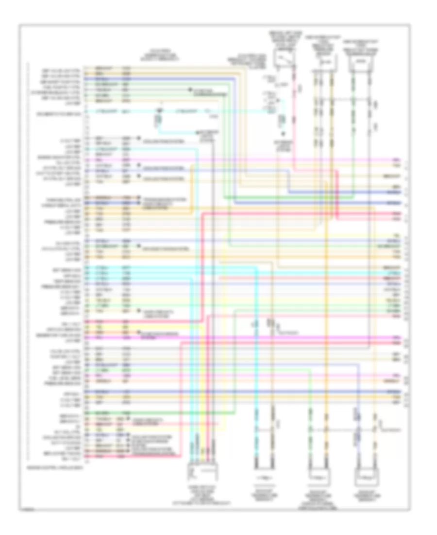
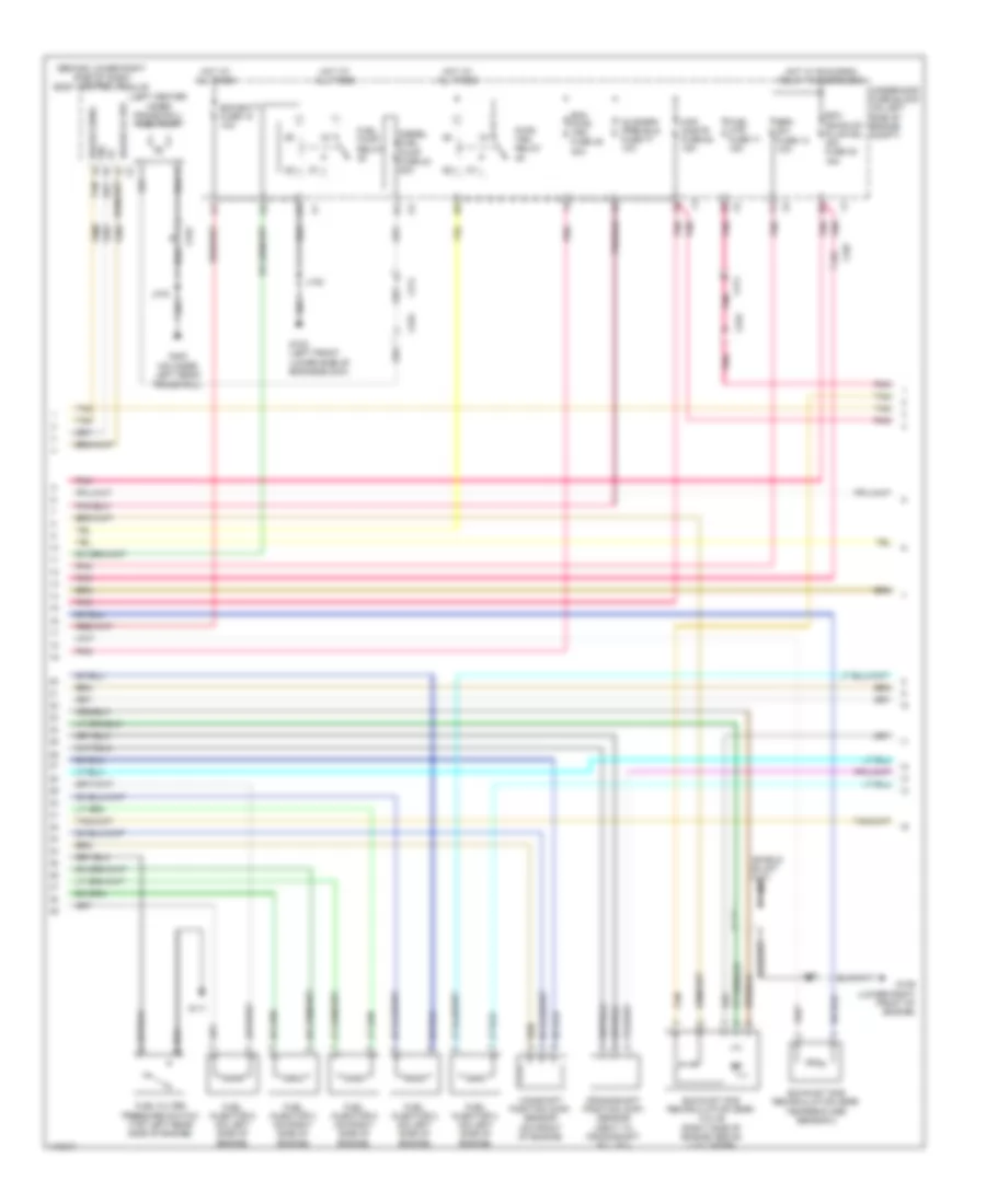
4.8L VIN A, Engine Performance Wiring Diagram (2 of 5) for GMC RV Cutaway G2013 3500
List of elements for 4.8L VIN A, Engine Performance Wiring Diagram (2 of 5) for GMC RV Cutaway G2013 3500:
- (on left rear of engine) g102
- (on right rear of engine) g103
- (or pnk)
- 4.8l
- 5.3l
- Air conditioning system
- Clutch rly ctrl
- Cnstr vent sol fuse 56 10a
- Computer data lines system
- Driver information center display
- Ecm pwr/trn fuse 78 10a
- Engine control module (ecm)
- Engine coolant radiator temperature sensors
- Evap sol ctrl
- Evaporative emission (evap) canister vent solenoid (near front of fuel tank)
- Even ign/ inj fuse 79 20a
- Flex fuel fuse 15a
- Fuel pump relay 38 (4.8l)
- G400 (on inner left rear frame rail)
- Gas fuel pump fuse 24 30a
- Gmlan ser data
- Gnd
- Ho2s hi sig
- Ho2s lo ctrl
- Hot at all times
- Ic 1 ctrl
- Ic 2 ctrl
- Ic 3 ctrl
- Ic 4 ctrl
- Ic 5 ctrl
- Ic 6 ctrl
- Ic 7 ctrl
- Ic 8 ctrl
- Instrument cluster
- J101
- J102
- Lo spd
- Logic
- Low engine oil pressure ind
- Low ref
- Maf/ cnstr vent fuse 64 15a
- Malfunction indicator lamp
- Mil ctrl
- O2 snsr 1 (pre)/cls fuse 77 10a
- O2 snsr 2 (post) fuse 62 10a
- Odd ign/inj fuse 65 20a
- Pnk
- Pwr/trn relay 49
- Tan
- Tos sig
- Transmissions system
- Underhood fuse block (on left side of engine compt)
- X100
- X101
- X127
- X150
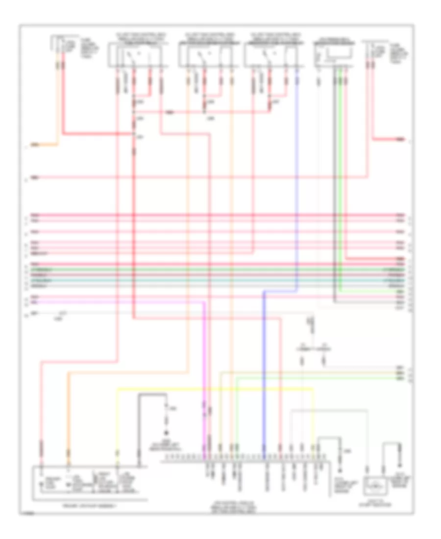
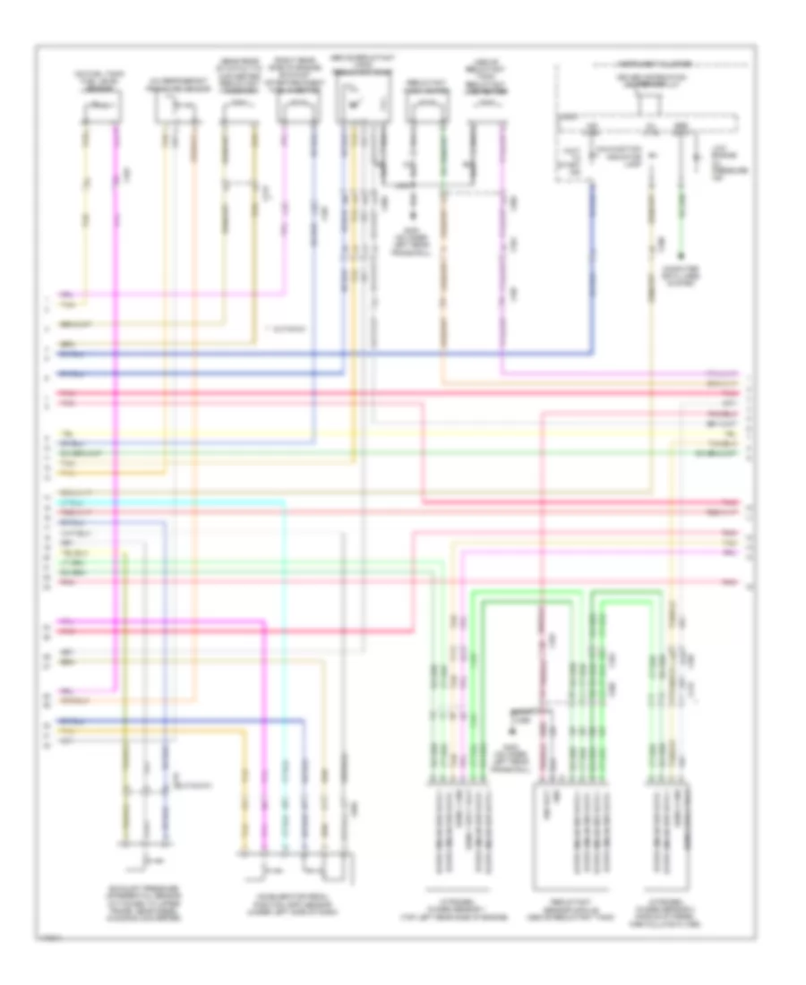
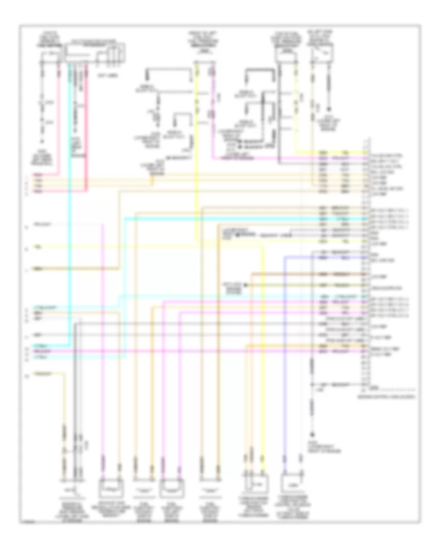
4.8L VIN A, Engine Performance Wiring Diagram (3 of 5) for GMC RV Cutaway G2013 3500
List of elements for 4.8L VIN A, Engine Performance Wiring Diagram (3 of 5) for GMC RV Cutaway G2013 3500:
- (at rear of vehicle, attached to left rear frame rail) (5.3l) fuel pump flow control module
- (at top left of engine)
- (in odd ignition/coil module jumper harness, on top left side of engine)
- 5v ref
- Body control module (behind lower right side of dash)
- Brake lo ref
- Brake sens sig
- Computer data lines system
- Fcsm batt fuse 36 20a
- Fscm ign fuse 6 10a
- G102 (on left rear of engine)
- G300 (on left frame rail, near ebcm)
- Gmlan data +
- Gmlan data -
- Gnd
- Hot at all times
- Hot w/ run/ crnk relay 15 energized
- Ign volt
- Ignition coil/module 1
- Ignition coil/module 3
- Ignition coil/module 5
- Ignition coil/module 7
- J102
- J182
- J184 (in odd ignition/coil module jumper harness, on top left side of engine)
- J187
- J315
- Low ref
- Nca
- Pnk
- Pnk d
- Pump ctrl
- Red c
- Relay ctrl
- Sens sig
- Serial data
- Spark plug
- Tan
- Underhood fuse block (on left side of engine compt)
- X126
4.8L VIN A, Engine Performance Wiring Diagram (4 of 5) for GMC RV Cutaway G2013 3500
List of elements for 4.8L VIN A, Engine Performance Wiring Diagram (4 of 5) for GMC RV Cutaway G2013 3500:
- (at top right of engine)
- (in even ignition/coil module jumper harness, on top right side of engine)
- (in even ignition/coil module jumper harness, on top right side of engine) j183
- (on left side of intake manifold)
- (on right side of intake manifold)
- C10
- Engine oil pressure (eop) sensor (on top rear of engine)
- Fuel composition sensor
- Fuel injector 1
- Fuel injector 2
- Fuel injector 3
- Fuel injector 4
- Fuel injector 5
- Fuel injector 6
- Fuel injector 7
- Fuel injector 8
- Fuel rail pressure (fpr) sensor
- G102 (on left rear of engine)
- G103 (on right rear of engine)
- Ignition coil/module 2
- Ignition coil/module 4
- Ignition coil/module 6
- Ignition coil/module 8
- J101
- J102
- J185
- J188
- Nca
- Pnk
- Pnk d
- Red c
- Spark plug
- Tan
- X101
- X127
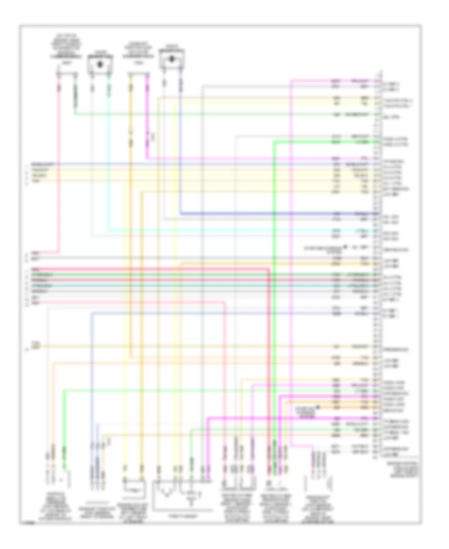
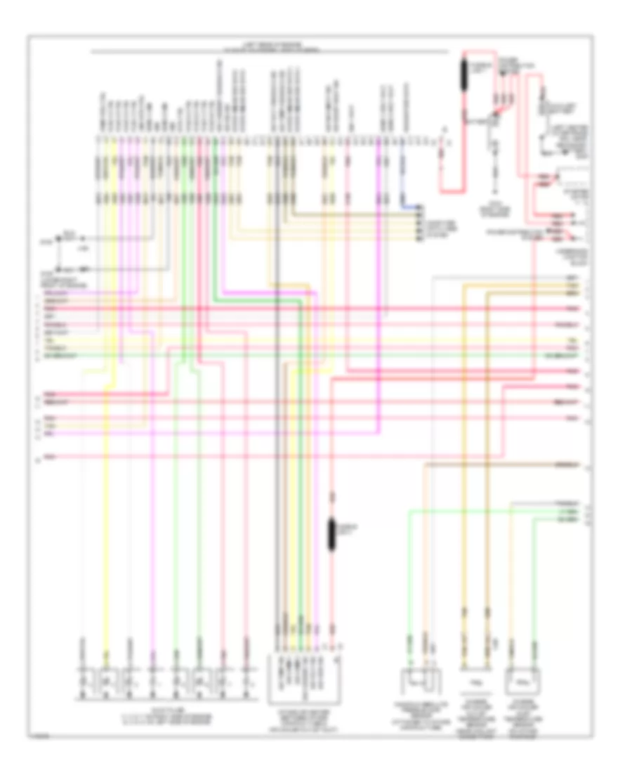
4.8L VIN A, Engine Performance Wiring Diagram (5 of 5) for GMC RV Cutaway G2013 3500
List of elements for 4.8L VIN A, Engine Performance Wiring Diagram (5 of 5) for GMC RV Cutaway G2013 3500:
- (on top of engine, near throttle body) evaporative emission (evap) canister purge solenoid valve
- 5v ref 1
- 5v ref 2
- Camshaft position (cmp) sensor (front of engine)
- Cen field sig
- Ckp sens sig
- Cmp sens sig
- Crankshaft position (ckp) sensor (on lower right rear of engine, near starter motor)
- Ect sens sig
- Engine control module (ecm)
- Engine coolant temperature (ect) sensor (at left front of engine)
- Gen on sig
- Heated oxygen sensor (ho2s) bank 1 sensor 1 (in exhaust pipe, in front of catalytic converter)
- Heated oxygen sensor (ho2s) bank 2 sensor 1 (in exhaust pipe, in front of catalytic converter)
- Ho2s hi sig
- Ho2s lo ctrl
- Ho2s lo sig
- Inj 1 ctrl
- Inj 2 ctrl
- Inj 3 ctrl
- Inj 4 ctrl
- Inj 5 ctrl
- Inj 6 ctrl
- Inj 7 ctrl
- Inj 8 ctrl
- Knock sensor (ks) 1
- Knock sensor (ks) 2
- Ks 1 sig
- Ks 2 sig
- Low ref
- Manifold absolute pressure (map) sensor (at top rear of engine, on intake manifold)
- Map sens sig
- Pnk
- Pnk d
- Pre sens sig
- Sol ctrl
- Starting/ charging system
- Starting/charging system
- Tac mtr ctrl 1
- Tac mtr ctrl 2
- Tan
- Tan a
- Throttle body
- Tp sens 1 sig
- Tp sens 2 sig
- X177
6.0L VIN B
6.0L VIN B, Engine Performance Wiring Diagram (1 of 7) for GMC RV Cutaway G2013 3500
List of elements for 6.0L VIN B, Engine Performance Wiring Diagram (1 of 7) for GMC RV Cutaway G2013 3500:
- (at left front of engine)
- (cutaway: in chassis harness, 87 cm from ebcm connector breakout) (passenger/cargo: in chassis harness, 44 cm from ebcm connector breakout)
- (in engine harness, 16 cm from underhood fuse block x1 breakout) j123
- (in exhaust pipe, in back of catalytic converter) heated oxygen sensor (ho2s) bank 1 sensor 2
- (in exhaust pipe, in back of catalytic converter) heated oxygen sensor (ho2s) bank 2 sensor 2
- (in instrument panel harness, 5 cm from x200 breakout towards instrument panel cluster)
- (on inner left rear frame rail)
- (or 6049)
- 5v ref 1
- 5v ref 2
- 6.0l vin b
- 6.0l vin g 6.0l vin b
- A/c refrigerant pressure sensor
- Acc ser data
- Accelerator pedal position (app) sensor (under left side of dash)
- Anti-lock brakes system
- App sens 1 sig
- App sens 2 sig
- Batt pos volt
- Brake pedal position (bpp) sensor (top of brake pedal assembly)
- Brk sens sig
- Brk sens sply
- Brk sw fuse 10a
- Cng fuel vehicle
- Computer data lines system
- Cutaway
- Ecm batt fuse 10a
- Ecm ign/ glow plug mdl ign fuse 15a
- Ect sens sig
- Engine control module (ecm) (left side of engine compt)
- Engine coolant radiator temperature sensor
- Exterior lights system
- Fuel level sens
- Fuel pump & sender assembly (on fuel tank)
- Fuel tank pressure (ftp) sensor (on fuel tank)
- G103 (on right rear of engine)
- G400
- Gmlan data+
- Gmlan data-
- Ho2s hi sig
- Ho2s lo sig
- Hot at all times
- Hot w/ run/ crank relay 15 energized
- Iat sens sig
- Ign volt
- J101
- J231
- J301
- J402
- Low ref
- Lpg fuel vehicle w/ 3 tank
- Lpg fuel vehicle w/ 4 tank
- Maf sens sig
- Mass air flow (maf)/intake air temperature (iat) sensor (attached to air intake duct)
- Park/neutral sig
- Pnk
- Press sens sig
- Pwrtrn rly ctrl
- Relay ctrl
- Start rly ctrl
- Starting/ charging system
- Stop lamp switch (behind left side of dash, above brake pedal)
- Tan
- Tan c
- Tcc brake sig
- Transmissions system
- Underhood fuse block (on left side of engine compt)
- Vss
- X100
- X101
- X103
- X128
- X150
- X221
- X350
6.0L VIN B, Engine Performance Wiring Diagram (2 of 7) for GMC RV Cutaway G2013 3500
List of elements for 6.0L VIN B, Engine Performance Wiring Diagram (2 of 7) for GMC RV Cutaway G2013 3500:
- (on right rear of engine) g103
- (on right side of intake manifold)
- (or red) pnk
- Clutch rly ctrl
- Cnstr vent sol fuse 10a
- Computer data lines system
- Ecm pwr/trn fuse 10a
- Engine control module (ecm) (left side of engine compt)
- Engine controls ignition relay
- Evap sol ctrl
- Evaporative emission vent solenoid (near front of fuel tank)
- Even ign/ inj fuse 20a
- Flex fuel fuse 15a
- Fuel injector 2
- Fuel injector 4
- Gnd
- Ho2s hi sig
- Ho2s lo ctrl
- Hot at all times
- Ic 1 ctrl
- Ic 2 ctrl
- Ic 3 ctrl
- Ic 4 ctrl
- Ic 5 ctrl
- Ic 6 ctrl
- Ic 7 ctrl
- Ic 8 ctrl
- Instrument panel cluster (ipc)
- J101
- Logic
- Low engine oil pressure ind
- Low ref
- Maf/ cnstr vent fuse 15a
- Malfunction indicator lamp (mil)
- Mil
- Mil ctrl
- O2 snsr 1 (pre)/ cls fuse 10a
- O2 snsr 2 (post) fuse 10a
- Odd ign/inj fuse 20a
- Pnk
- Pnk (or red)
- Tos sig
- Transmissions system air conditioning system
- Underhood fuse block (on left side of engine compt)
- W/ 3 tank
- W/ 4 tank
- X100
- X101
- X127
- X162
- X164
6.0L VIN B, Engine Performance Wiring Diagram (3 of 7) for GMC RV Cutaway G2013 3500
List of elements for 6.0L VIN B, Engine Performance Wiring Diagram (3 of 7) for GMC RV Cutaway G2013 3500:
- (at top left of engine)
- (forward of left rear spring on frame) cng control module
- (in odd ignition/coil module jumper harness, on top left side of engine)
- (left rear of axle between frame rails)
- (not used)
- (on left side of intake manifold)
- (or red) pnk
- 12v
- 5 volt ref
- Alternative fuel tank pressure sensor
- C10
- Cng cutt-off solenoid valve 2
- Cng cutt-off solenoid valve 3
- Cng sol vlv ctrl
- Fuel composition sensor
- Fuel injector 3
- Fuel injector 7
- G102 (on left rear of engine)
- G103 (on right rear of engine)
- G350 (rear of transmission case)
- G400 (on inner left rear frame rail)
- Gnd
- Ignition coil 1
- Ignition coil 3
- Ignition coil 5
- Ignition coil 7
- J101
- J102
- J182
- J184 (in odd ignition/coil module jumper harness, on top left side of engine)
- Low ref
- Nca
- Pnk
- Pnk d
- Pressure sig
- Red
- Red c
- Sensing
- Spark plug
- W/ 3 tank
- W/ 4 tank
- X101
- X126
- X163
- X167
- X350
6.0L VIN B, Engine Performance Wiring Diagram (4 of 7) for GMC RV Cutaway G2013 3500
List of elements for 6.0L VIN B, Engine Performance Wiring Diagram (4 of 7) for GMC RV Cutaway G2013 3500:
- (at top right of engine)
- (front of cng control module near ebcm) cng high pressure regulator solenoid valve
- (inboard side of left frame rail near ebcm) cng cutt-off solenoid valve 1
- (left rear of axle between frame rails) cng cutt-off solenoid valve 4
- Fuel pump relay
- G102 (on left rear of engine)
- G400 (on inner left rear frame rail)
- Gas fuel pump fuse 30a
- Hot at all times
- Ignition coil 2
- Ignition coil 4
- Ignition coil 6
- Ignition coil 8
- J102
- J183
- J185
- J188 (in even ignition/coil module jumper harness, on top right side of engine)
- J362
- Mega fuse 125a
- Natural gas
- Nca
- Pnk
- Pnk d
- Rear lpg cut-off solenoid valve
- Red
- Red c
- Regular gas
- Regular gas w/ 3 tank
- Regular gas w/ 4 tank
- Secondary fuel pump
- Secondary lpg pump assembly
- Spark plug
- Underhood fuse block (on left side of engine compt)
- X127
6.0L VIN B, Engine Performance Wiring Diagram (5 of 7) for GMC RV Cutaway G2013 3500
List of elements for 6.0L VIN B, Engine Performance Wiring Diagram (5 of 7) for GMC RV Cutaway G2013 3500:
- (in lpg tank control box) (regular gas w/ 4 tank) fuel pump relay
- (in lpg tank control box) (regular gas w/ 4 tank) lpg tank scavenge pump relay
- (in lpg tank control box) (regular gas w/ 4 tank) secondary fuel pump relay
- 12 volt ref
- Batt pos volt
- C (not used)
- Front lpg cut-off solenoid valve
- Fuel gauge sig
- Fuse holder (regular gas w/ 3 tank)
- Fuse holder (regular gas w/ 4 tank)
- G110 (lower left front of engine)
- G400 (on inner left rear frame rail)
- Gnd
- J361
- J362
- J364
- J365 red
- J366
- J367 red
- J368
- Lpcm fuse 20a
- Lpcm fuse 30a
- Lpg control module (regular gas w/ 4 tank) (on tank control box)
- Lpg pressure & temperature sensor
- Lpg purge sole- noid valve
- Lpg tank scavenge pump
- Pnk
- Primary fuel pump
- Primary lpg pump assembly
- Primary sig
- Pump sig
- Red
- Red j363
- Rly sig
- Secondary sig
- Strt lmp
- W/ 3 tank
- W/ 4 tank
- Wait to start indicator
- X350
6.0L VIN B, Engine Performance Wiring Diagram (6 of 7) for GMC RV Cutaway G2013 3500
List of elements for 6.0L VIN B, Engine Performance Wiring Diagram (6 of 7) for GMC RV Cutaway G2013 3500:
- (in lpg fuel tank harness, 152.5 mm from x180)
- (next to brake booster taped to harness) (regular gas w/ 3 tank) wait to start indicator relay
- (on fuel tank) (regular gas w/ 3 tank) lpg bypass solenoid valve
- (on left front of engine compt)
- (on left side of intake manifold)
- (on right side of intake manifold)
- (regular gas w/ 3 tank) lpg bypass solenoid valve relay
- (regular gas w/ 3 tank) wait to start indicator
- 5 volt ref
- Batt pos vlt
- Engine oil pressure (eop) sensor (on top rear of engine)
- Evaporative emission system leak detection pump
- Fuel cutoff solenoid valve
- Fuel injector 1
- Fuel injector 5
- Fuel injector 6
- Fuel injector 8
- Fuel injector control module
- Fuel pump
- Fuel temp sig
- G100
- G100 (on left front of engine compt)
- G110 (lower left front of engine)
- G400 (on inner left rear frame rail)
- J167
- J168
- J169
- J170
- J171
- J172
- J176
- J179
- J368
- J430
- J431
- J432
- Pmp sig
- Pnk
- Pnk (or red)
- Press sig
- Primary fuel level sensor (6.0l vin b) (front of primary fuel tank)
- Red
- Rely volt
- Resistor
- Rly sig
- Secondary fuel level sensor (6.0l vin b) (front of secondary fuel tank)
- Sol rly sig
- Tan
- Temp sens
- W/ 3 tank
- W/ 4 tank
- X161
- X165
- X166
- X168
- X180
- X350
6.0L VIN B, Engine Performance Wiring Diagram (7 of 7) for GMC RV Cutaway G2013 3500
List of elements for 6.0L VIN B, Engine Performance Wiring Diagram (7 of 7) for GMC RV Cutaway G2013 3500:
- (on top of engine, near throttle body) evaporative emission purge solenoid
- 5v ref 1
- 5v ref 2
- Camshaft position (cmp) actuator solenoid valve
- Camshaft position (cmp) sensor (front of engine)
- Cen field sig
- Ckp sens sig
- Cmp sens sig
- Crankshaft position (ckp) sensor (on lower right rear of engine, near starter motor)
- Ect sens sig
- Engine control module (ecm) (left side of engine compt)
- Engine coolant temperature (ect) sensor (at left front of engine)
- Gen on sig
- Heated oxygen sensor (ho2s) bank 1 sensor 1 (in exhaust pipe, in front of catalytic converter)
- Heated oxygen sensor (ho2s) bank 2 sensor 1 (in exhaust pipe, in front of catalytic converter)
- Ho2s hi sig
- Ho2s lo ctrl
- Ho2s lo sig
- Inj 1 ctrl
- Inj 2 ctrl
- Inj 3 ctrl
- Inj 4 ctrl
- Inj 5 ctrl
- Inj 6 ctrl
- Inj 7 ctrl
- Inj 8 ctrl
- Intake sol
- Knock sensor (ks) 1
- Knock sensor (ks) 2
- Ks 1 sig
- Ks 2 sig
- Low ref
- Manifold absolute pressure (map) sensor (at top rear of engine, on intake manifold)
- Map sens sig
- Pnk
- Pnk d
- Pre sens sig
- Sol ctrl
- Starting/ charging system
- Starting/charging system
- Tac mtr ctrl 1
- Tac mtr ctrl 2
- Tan
- Tan a
- Throttle body
- Tp sens 1 sig
- Tp sens 2 sig
- X177
6.0L VIN G
6.0L VIN G, Engine Performance Wiring Diagram (1 of 7) for GMC RV Cutaway G2013 3500
List of elements for 6.0L VIN G, Engine Performance Wiring Diagram (1 of 7) for GMC RV Cutaway G2013 3500:
- (at left front of engine)
- (cutaway: in chassis harness, 87 cm from ebcm connector breakout) (passenger/cargo: in chassis harness, 44 cm from ebcm connector breakout)
- (in engine harness, 16 cm from underhood fuse block x1 breakout) j123
- (in exhaust pipe, in back of catalytic converter) heated oxygen sensor (ho2s) bank 1 sensor 2
- (in exhaust pipe, in back of catalytic converter) heated oxygen sensor (ho2s) bank 2 sensor 2
- (in instrument panel harness, 5 cm from x200 breakout towards instrument panel cluster)
- (on inner left rear frame rail)
- (or 6049)
- 5v ref 1
- 5v ref 2
- 6.0l vin b
- 6.0l vin g 6.0l vin b
- A/c refrigerant pressure sensor
- Acc ser data
- Accelerator pedal position (app) sensor (under left side of dash)
- Anti-lock brakes system
- App sens 1 sig
- App sens 2 sig
- Batt pos volt
- Brake pedal position (bpp) sensor (top of brake pedal assembly)
- Brk sens sig
- Brk sens sply
- Brk sw fuse 10a
- Cng fuel vehicle
- Computer data lines system
- Cutaway
- Ecm batt fuse 10a
- Ecm ign/ glow plug mdl ign fuse 15a
- Ect sens sig
- Engine control module (ecm) (left side of engine compt)
- Engine coolant radiator temperature sensor
- Exterior lights system
- Fuel level sens
- Fuel pump & sender assembly (on fuel tank)
- Fuel tank pressure (ftp) sensor (on fuel tank)
- G103 (on right rear of engine)
- G400
- Gmlan data+
- Gmlan data-
- Ho2s hi sig
- Ho2s lo sig
- Hot at all times
- Hot w/ run/ crank relay 15 energized
- Iat sens sig
- Ign volt
- J101
- J231
- J301
- J402
- Low ref
- Lpg fuel vehicle w/ 3 tank
- Lpg fuel vehicle w/ 4 tank
- Maf sens sig
- Mass air flow (maf)/intake air temperature (iat) sensor (attached to air intake duct)
- Park/neutral sig
- Pnk
- Press sens sig
- Pwrtrn rly ctrl
- Relay ctrl
- Start rly ctrl
- Starting/ charging system
- Stop lamp switch (behind left side of dash, above brake pedal)
- Tan
- Tan c
- Tcc brake sig
- Transmissions system
- Underhood fuse block (on left side of engine compt)
- Vss
- X100
- X101
- X103
- X128
- X150
- X221
- X350
6.0L VIN G, Engine Performance Wiring Diagram (2 of 7) for GMC RV Cutaway G2013 3500
List of elements for 6.0L VIN G, Engine Performance Wiring Diagram (2 of 7) for GMC RV Cutaway G2013 3500:
- (on right rear of engine) g103
- (on right side of intake manifold)
- (or red) pnk
- Clutch rly ctrl
- Cnstr vent sol fuse 10a
- Computer data lines system
- Ecm pwr/trn fuse 10a
- Engine control module (ecm) (left side of engine compt)
- Engine controls ignition relay
- Evap sol ctrl
- Evaporative emission vent solenoid (near front of fuel tank)
- Even ign/ inj fuse 20a
- Flex fuel fuse 15a
- Fuel injector 2
- Fuel injector 4
- Gnd
- Ho2s hi sig
- Ho2s lo ctrl
- Hot at all times
- Ic 1 ctrl
- Ic 2 ctrl
- Ic 3 ctrl
- Ic 4 ctrl
- Ic 5 ctrl
- Ic 6 ctrl
- Ic 7 ctrl
- Ic 8 ctrl
- Instrument panel cluster (ipc)
- J101
- Logic
- Low engine oil pressure ind
- Low ref
- Maf/ cnstr vent fuse 15a
- Malfunction indicator lamp (mil)
- Mil
- Mil ctrl
- O2 snsr 1 (pre)/ cls fuse 10a
- O2 snsr 2 (post) fuse 10a
- Odd ign/inj fuse 20a
- Pnk
- Pnk (or red)
- Tos sig
- Transmissions system air conditioning system
- Underhood fuse block (on left side of engine compt)
- W/ 3 tank
- W/ 4 tank
- X100
- X101
- X127
- X162
- X164
6.0L VIN G, Engine Performance Wiring Diagram (3 of 7) for GMC RV Cutaway G2013 3500
List of elements for 6.0L VIN G, Engine Performance Wiring Diagram (3 of 7) for GMC RV Cutaway G2013 3500:
- (at top left of engine)
- (forward of left rear spring on frame) cng control module
- (in odd ignition/coil module jumper harness, on top left side of engine)
- (left rear of axle between frame rails)
- (not used)
- (on left side of intake manifold)
- (or red) pnk
- 12v
- 5 volt ref
- Alternative fuel tank pressure sensor
- C10
- Cng cutt-off solenoid valve 2
- Cng cutt-off solenoid valve 3
- Cng sol vlv ctrl
- Fuel composition sensor
- Fuel injector 3
- Fuel injector 7
- G102 (on left rear of engine)
- G103 (on right rear of engine)
- G350 (rear of transmission case)
- G400 (on inner left rear frame rail)
- Gnd
- Ignition coil 1
- Ignition coil 3
- Ignition coil 5
- Ignition coil 7
- J101
- J102
- J182
- J184 (in odd ignition/coil module jumper harness, on top left side of engine)
- Low ref
- Nca
- Pnk
- Pnk d
- Pressure sig
- Red
- Red c
- Sensing
- Spark plug
- W/ 3 tank
- W/ 4 tank
- X101
- X126
- X163
- X167
- X350
6.0L VIN G, Engine Performance Wiring Diagram (4 of 7) for GMC RV Cutaway G2013 3500
List of elements for 6.0L VIN G, Engine Performance Wiring Diagram (4 of 7) for GMC RV Cutaway G2013 3500:
- (at top right of engine)
- (front of cng control module near ebcm) cng high pressure regulator solenoid valve
- (inboard side of left frame rail near ebcm) cng cutt-off solenoid valve 1
- (left rear of axle between frame rails) cng cutt-off solenoid valve 4
- Fuel pump relay
- G102 (on left rear of engine)
- G400 (on inner left rear frame rail)
- Gas fuel pump fuse 30a
- Hot at all times
- Ignition coil 2
- Ignition coil 4
- Ignition coil 6
- Ignition coil 8
- J102
- J183
- J185
- J188 (in even ignition/coil module jumper harness, on top right side of engine)
- J362
- Mega fuse 125a
- Natural gas
- Nca
- Pnk
- Pnk d
- Rear lpg cut-off solenoid valve
- Red
- Red c
- Regular gas
- Regular gas w/ 3 tank
- Regular gas w/ 4 tank
- Secondary fuel pump
- Secondary lpg pump assembly
- Spark plug
- Underhood fuse block (on left side of engine compt)
- X127
6.0L VIN G, Engine Performance Wiring Diagram (5 of 7) for GMC RV Cutaway G2013 3500
List of elements for 6.0L VIN G, Engine Performance Wiring Diagram (5 of 7) for GMC RV Cutaway G2013 3500:
- (in lpg tank control box) (regular gas w/ 4 tank) fuel pump relay
- (in lpg tank control box) (regular gas w/ 4 tank) lpg tank scavenge pump relay
- (in lpg tank control box) (regular gas w/ 4 tank) secondary fuel pump relay
- 12 volt ref
- Batt pos volt
- C (not used)
- Front lpg cut-off solenoid valve
- Fuel gauge sig
- Fuse holder (regular gas w/ 3 tank)
- Fuse holder (regular gas w/ 4 tank)
- G110 (lower left front of engine)
- G400 (on inner left rear frame rail)
- Gnd
- J361
- J362
- J364
- J365 red
- J366
- J367 red
- J368
- Lpcm fuse 20a
- Lpcm fuse 30a
- Lpg control module (regular gas w/ 4 tank) (on tank control box)
- Lpg pressure & temperature sensor
- Lpg purge sole- noid valve
- Lpg tank scavenge pump
- Pnk
- Primary fuel pump
- Primary lpg pump assembly
- Primary sig
- Pump sig
- Red
- Red j363
- Rly sig
- Secondary sig
- Strt lmp
- W/ 3 tank
- W/ 4 tank
- Wait to start indicator
- X350
6.0L VIN G, Engine Performance Wiring Diagram (6 of 7) for GMC RV Cutaway G2013 3500
List of elements for 6.0L VIN G, Engine Performance Wiring Diagram (6 of 7) for GMC RV Cutaway G2013 3500:
- (in lpg fuel tank harness, 152.5 mm from x180)
- (next to brake booster taped to harness) (regular gas w/ 3 tank) wait to start indicator relay
- (on fuel tank) (regular gas w/ 3 tank) lpg bypass solenoid valve
- (on left front of engine compt)
- (on left side of intake manifold)
- (on right side of intake manifold)
- (regular gas w/ 3 tank) lpg bypass solenoid valve relay
- (regular gas w/ 3 tank) wait to start indicator
- 5 volt ref
- Batt pos vlt
- Engine oil pressure (eop) sensor (on top rear of engine)
- Evaporative emission system leak detection pump
- Fuel cutoff solenoid valve
- Fuel injector 1
- Fuel injector 5
- Fuel injector 6
- Fuel injector 8
- Fuel injector control module
- Fuel pump
- Fuel temp sig
- G100
- G100 (on left front of engine compt)
- G110 (lower left front of engine)
- G400 (on inner left rear frame rail)
- J167
- J168
- J169
- J170
- J171
- J172
- J176
- J179
- J368
- J430
- J431
- J432
- Pmp sig
- Pnk
- Pnk (or red)
- Press sig
- Primary fuel level sensor (6.0l vin b) (front of primary fuel tank)
- Red
- Rely volt
- Resistor
- Rly sig
- Secondary fuel level sensor (6.0l vin b) (front of secondary fuel tank)
- Sol rly sig
- Tan
- Temp sens
- W/ 3 tank
- W/ 4 tank
- X161
- X165
- X166
- X168
- X180
- X350
6.0L VIN G, Engine Performance Wiring Diagram (7 of 7) for GMC RV Cutaway G2013 3500
List of elements for 6.0L VIN G, Engine Performance Wiring Diagram (7 of 7) for GMC RV Cutaway G2013 3500:
- (on top of engine, near throttle body) evaporative emission purge solenoid
- 5v ref 1
- 5v ref 2
- Camshaft position (cmp) actuator solenoid valve
- Camshaft position (cmp) sensor (front of engine)
- Cen field sig
- Ckp sens sig
- Cmp sens sig
- Crankshaft position (ckp) sensor (on lower right rear of engine, near starter motor)
- Ect sens sig
- Engine control module (ecm) (left side of engine compt)
- Engine coolant temperature (ect) sensor (at left front of engine)
- Gen on sig
- Heated oxygen sensor (ho2s) bank 1 sensor 1 (in exhaust pipe, in front of catalytic converter)
- Heated oxygen sensor (ho2s) bank 2 sensor 1 (in exhaust pipe, in front of catalytic converter)
- Ho2s hi sig
- Ho2s lo ctrl
- Ho2s lo sig
- Inj 1 ctrl
- Inj 2 ctrl
- Inj 3 ctrl
- Inj 4 ctrl
- Inj 5 ctrl
- Inj 6 ctrl
- Inj 7 ctrl
- Inj 8 ctrl
- Intake sol
- Knock sensor (ks) 1
- Knock sensor (ks) 2
- Ks 1 sig
- Ks 2 sig
- Low ref
- Manifold absolute pressure (map) sensor (at top rear of engine, on intake manifold)
- Map sens sig
- Pnk
- Pnk d
- Pre sens sig
- Sol ctrl
- Starting/ charging system
- Starting/charging system
- Tac mtr ctrl 1
- Tac mtr ctrl 2
- Tan
- Tan a
- Throttle body
- Tp sens 1 sig
- Tp sens 2 sig
- X177
6.6L VIN L
6.6L VIN L, Engine Performance Wiring Diagram (1 of 6) for GMC RV Cutaway G2013 3500
List of elements for 6.6L VIN L, Engine Performance Wiring Diagram (1 of 6) for GMC RV Cutaway G2013 3500:
- (16 cm from underhood fuse block x1 breakout)
- (5 cm from x200 breakout towards instrument panel cluster)
- (above reductant tank) reductant pressure sensor
- (above reductant tank) reductant purge solenoid valve
- (behind left side of dash, above brake pedal) stop lamp switch
- (cutaway) x101
- (cutaway) x115
- 5 volt ref
- A/c clutch rly ctrl
- Air conditioning system
- Air flow sens sig
- App sig 1
- App sig 2
- Cf ctrl rly spd sig
- Computer data lines system
- Cooling fan spd sig
- Cooling fans system
- Cooling fans system starting/charging system cooling fans system transmissions system
- Cruise/etc/tcc brk sig
- Def smart pump ctrl
- Def valve high ctrl
- Def valve low ctrl
- Duty cycle sig
- Egt sens 2 sig
- Egt sens 3 sig
- Egt sens 4 sig
- Engine control module (ecm)
- Engine indicator ctrl
- Exhaust temperature sensor 2
- Exhaust temperature sensor 3 (middle of diesel particulate filter)
- Exhaust temperature sensor 4
- Exterior lights system
- Fuel level sens
- Fuel pump rly ctrl
- Generator turn on sig
- Ign 1 volt
- Inj high ctrl
- Inj low ctrl
- J123
- J231
- Low ref
- Mass air flow (maf)/intake air temp (iat) sensor (attached to air intake duct)
- Nca
- Park/neutral sig
- Pnk
- Pressure sens sig
- Pressure sens sig 1
- Pump sply volt
- Replicated tos sig
- Rly coil ctrl
- Ser data +
- Ser data -
- Starter enable rly ctrl
- Starting/ charging system
- Starting/charging system
- Tan
- Temp sens sig
- Transmissions system
- Valve low ctrl
- Wait to start ind ctrl
- Wakeup serial data
- X100
- X101
- X174
- X221
- X395
6.6L VIN L, Engine Performance Wiring Diagram (2 of 6) for GMC RV Cutaway G2013 3500
List of elements for 6.6L VIN L, Engine Performance Wiring Diagram (2 of 6) for GMC RV Cutaway G2013 3500:
- (above reductant tank) reductant line heater
- (above reductant tank) reductant pump
- (cutaway)
- (near rear of catalytic converter) reductant injector
- (on fuel tank) fuel level sensor
- (right rear side of engine) exhaust aftertreatment fuel injector
- (top left rear side of engine)
- A/c refrigerant pressure sensor
- Accelerator pedal position (app) sensor (under left side of dash)
- B10
- C tan
- C10
- Computer data lines system
- Cutaway
- Driver information center display
- Exhaust pressure differential sensor (attached to upper frame, near diesel oxidizing converter)
- G400 (on inner left rear frame rail)
- Gnd
- Hi spd gmlan ser data +
- Hi spd gmlan ser data -
- Ign volt
- Ind ctrl
- Instrument cluster
- J402
- Logic
- Low engine oil pressure ind
- Malfunction indicator lamp
- Mil ctrl
- Nitrogen oxides sensor 1
- Nitrogen oxides sensor 2 (middle of diesel particulate filter)
- Pnk
- Reductant sensor module (above reductant tank)
- Reductant tank heater
- Sens 1 gnd
- Sens 1 sply volt
- Sens 2 gnd
- Sens 2 sply volt
- Ser data
- Tan
- Wait to start ind
- X100
- X101
- X107
- X115
- X395
6.6L VIN L, Engine Performance Wiring Diagram (3 of 6) for GMC RV Cutaway G2013 3500
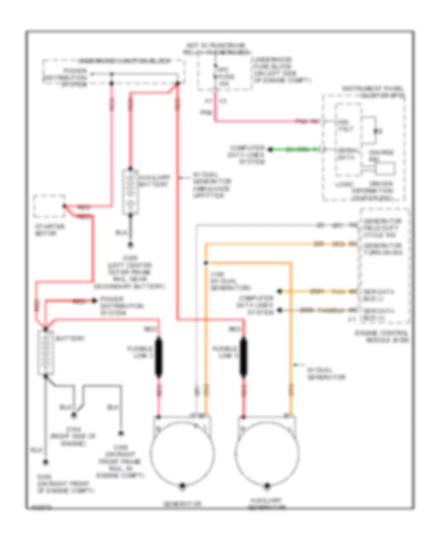
List of elements for 6.6L VIN L, Engine Performance Wiring Diagram (3 of 6) for GMC RV Cutaway G2013 3500:
- (left center outer frame rail near, secondary battery) g305
- (left rear of engine) glow plug control module (gpcm)
- Auxiliary battery
- Battery
- Charge air cooler inlet temperature sensor (on intake manifold)
- Charge air cooler outlet temperature sensor (near coolant surge tank)
- Computer data lines system
- Fusible link 1
- Fusible link 4
- G104 (right side of engine)
- G109
- G109 (lower right front of engine)
- Glow plugs (1, 3, 5, 7: on right side of engine) (2, 4, 6, 8: on left side of engine)
- Gnd
- Hi spd gmlan ser data +
- Hi spd gmlan ser data -
- Htr ctrl
- Iah comm 1
- Iah comm 2
- Iah current feedback sig
- Iah current sig
- Iah dig sig
- Iah fdbk sig
- Iah heart beat sig
- Iah sw on/off sig
- Iah temp feedback sig
- Iah temp sig
- Iah volt feedback sig
- Iah volt sig
- Ign 1 volt
- Intake air heater (between intake manifold tube & air cooler outlet duct)
- J160
- J162
- Line htr ctrl
- Manifold absolute pressue (map) sensor (attached to intake manifold tube)
- Plug 1 ctrl
- Plug 2 ctrl
- Plug 3 ctrl
- Plug 4 ctrl
- Plug 5 ctrl
- Plug 6 ctrl
- Plug 7 ctrl
- Plug 8 ctrl
- Pnk
- Pnk a
- Power distribution system
- Pump htr ctrl
- Red
- Sens 1 gnd
- Sens 1 sply volt
- Sens 2 gnd
- Sens 2 sply volt
- Starter motor
- Tan
- Underhood junction block
- Wakeup ser data
- X107
6.6L VIN L, Engine Performance Wiring Diagram (4 of 6) for GMC RV Cutaway G2013 3500
List of elements for 6.6L VIN L, Engine Performance Wiring Diagram (4 of 6) for GMC RV Cutaway G2013 3500:
- (left side of fuel injection pump) fuel temperature sensor 1
- (on top right side of engine) fuel rail pressure (frp) sensor
- (rear of left fuel rail) fuel temperature sensor 2
- (top of brake pedal assembly) brake pedal position (bpp) sensor
- (top of engine, near thermostat housing) engine coolant temperature (ect) sensor
- 5 volt ref
- Act ctrl close
- Act ctrl open
- B tan
- Brk aply sens sig
- Cac temp sens rtn
- Cac temp sens sig
- Ckp sens sig
- Cmp sens sig
- Ctrl cyl 2
- Ctrl cyl 3
- Ctrl cyl 5
- Ctrl cyl 8
- Ect sens sig
- Egr valve sens sig
- Egrt sens 1 sply volt
- Egrt sens 2 sply volt
- Egrv mtr high sig
- Egrv mtr low sig
- Egt sens 1 sig
- Engine control module (ecm)
- Exhaust temperature sensor 1
- Fuel temp 1 sig
- Fuel temp sig
- G109 (lower right front of engine)
- Gnd
- Intake air flow valve
- J160
- Low ref
- Nca
- Oil pressure sens sig
- Pnk
- Pos sens sig
- Pos sens sig 1
- Pressure sens sig
- Pressure sw sig
- Sens sply volt
- Sply cyl 2
- Sply cyl 3
- Sply cyl 5
- Sply cyl 8
- Tan
- Temp 1 rtn
- Temp sens rtn
- Temp sens sig
- Water in fuel sens sig
- Water in fuel sensor
- X101
- X103
- X107
- X110
- X111
- X112
- X174
- X316
6.6L VIN L, Engine Performance Wiring Diagram (5 of 6) for GMC RV Cutaway G2013 3500
List of elements for 6.6L VIN L, Engine Performance Wiring Diagram (5 of 6) for GMC RV Cutaway G2013 3500:
- (behind lower right side of dash) body control module
- (left center inner frame rail) fuel pump
- (on inner left rear frame rail)
- B2 pnk
- B5 pnk
- Brake lo ref
- Brk sw fuse 13 10a
- C1 pnk
- Camshaft position (cmp) sensor (on front of engine)
- Crankshaft position (ckp) sensor (next to crankshaft pulley)
- Diesel fuel pump fuse 24 20a
- Ecm batt fuse 19 10a
- Ecm ign/glow plug mdl ign fuse 30 15a
- Ecm pwr/ trn fuse 45 30a
- Exhaust gas recirculation (egr) temperature sensor 2
- Exhaust gas recirculation (egr) valve (right side of engine above 1 cylinder)
- Fuel filter pressure switch (top left rear side of engine)
- Fuel htr fuse 71 15a
- Fuel injector 2 (on left side of engine)
- Fuel injector 3 (on right side of engine)
- Fuel injector 4 (on left side of engine)
- Fuel injector 5 (on right side of engine)
- Fuel injector 8 (on left side of engine)
- Fuel pump relay
- G102 (left front lower side of engine block)
- G109 (lower right front of engine)
- G111
- G4 pnk
- G400
- Hot at all times
- Hot w/ run/crnk relay 15 energized
- J102
- J161
- J316
- Maf/ cnstr fuse 64 15a
- Nca
- O2 snsr1 (pre)/sls fuse 77 10a
- Pnk
- Pwr/ trn relay
- Sig brake sens
- Tan
- Underhood fuse block (on left side of engine compt)
- X107
- X174
- X316
6.6L VIN L, Engine Performance Wiring Diagram (6 of 6) for GMC RV Cutaway G2013 3500
List of elements for 6.6L VIN L, Engine Performance Wiring Diagram (6 of 6) for GMC RV Cutaway G2013 3500:
- (front of left fuel rail) fuel pressure regulator 2
- (lower left front of engine)
- (lower right front of engine)
- (lower right front of engine) g109
- (not used)
- (on inner left rear frame rail)
- (on left side of oil pan) engine oil level switch
- (pins 33-40 not used)
- (pins 42-46 not used)
- (pins 48-65 not used)
- (top of fuel injection pump) fuel pressure regulator 1
- (top of fuel pump assembly) fuel heater
- 5 volt ref
- Anti-lock brakes system
- B pnk
- Dfi volt ctrl cyl 1
- Dfi volt ctrl cyl 4
- Dfi volt ctrl cyl 6
- Dfi volt ctrl cyl 7
- Dfi volt sply cyl 1
- Dfi volt sply cyl 4
- Dfi volt sply cyl 6
- Dfi volt sply cyl 7
- Engine control module (ecm)
- Engine oil pressure (eop) sensor (lower left side of engine)
- Exhaust gas recirculation (egr) temperature sensor 1
- Fuel injector 1 (on right side of engine)
- Fuel injector 6 (on left side of engine)
- Fuel injector 7 (on right side of engine)
- G103 (left rear of engine)
- G109
- G109 (lower right front of engine)
- G110
- G110 (lower left front of engine)
- G400
- Gnd
- J101
- J160
- J161
- J164
- J316
- Low ref
- Multi-function intake air sensor
- Nca
- Oil level sw sig
- Pnk
- Sens volt ref
- Sol high sig
- Sol low sig
- Sol sply volt
- Tan
- Turbocharger vane position control solenoid valve (at right side of turbocharger)
- Turbocharger vane position sensor (on top of turbocharger)
- Valve high ctrl
- Valve low ctrl
- Vehicle spd sig
- X110
- X316
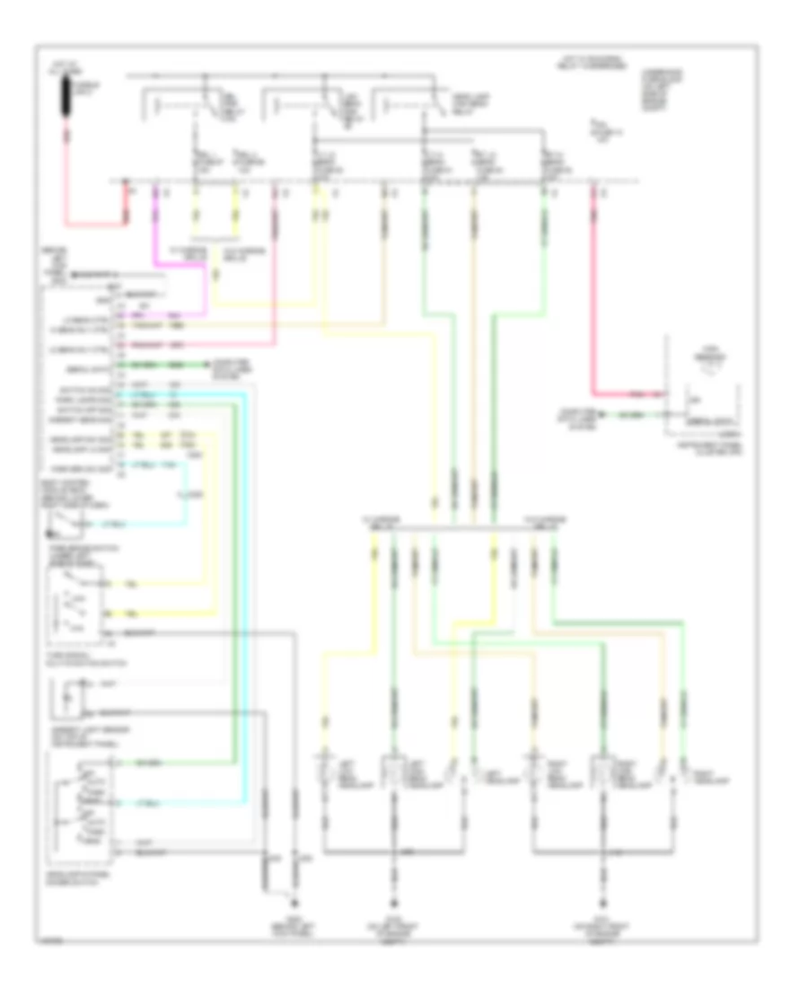
EXTERIOR LIGHTS
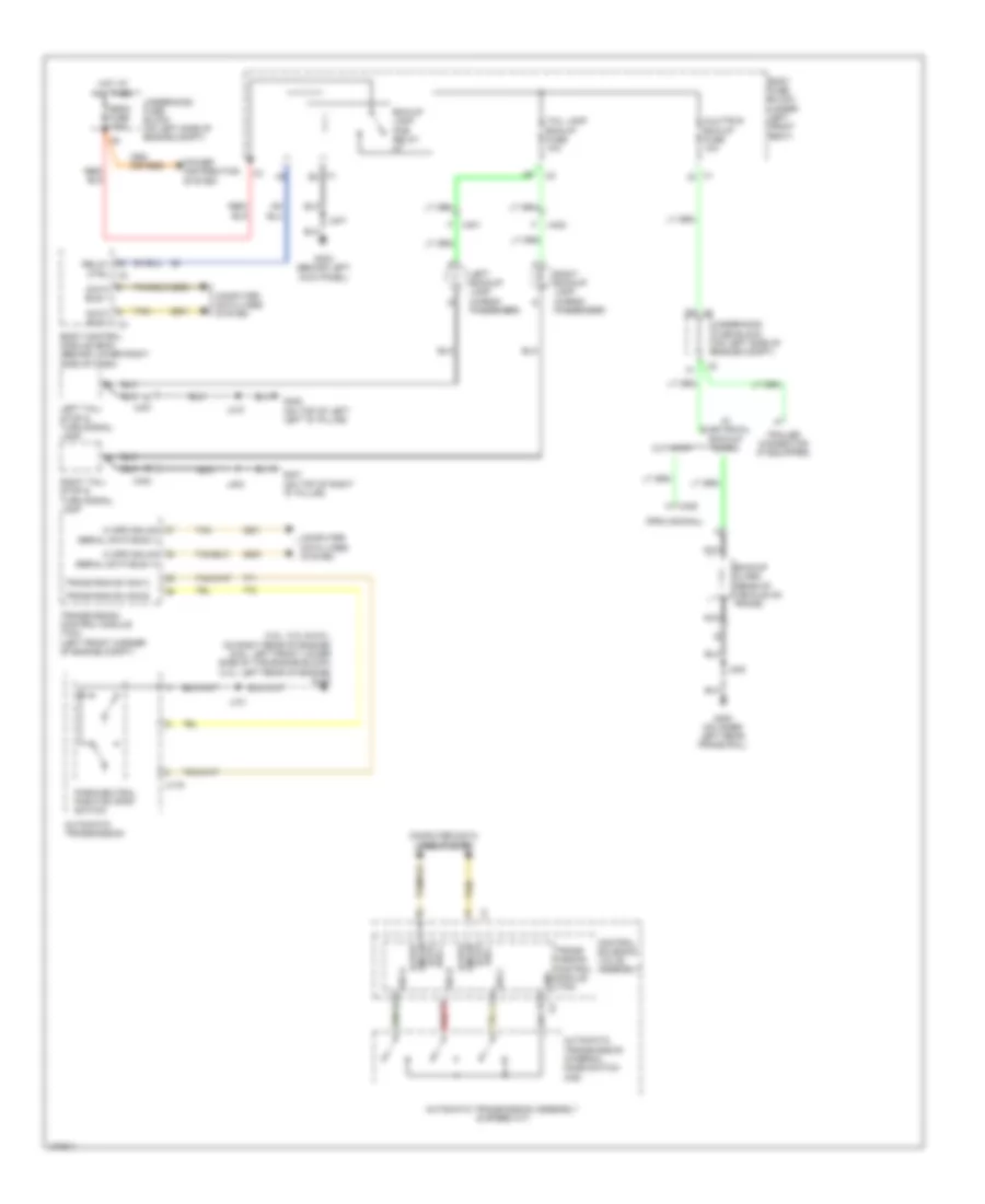
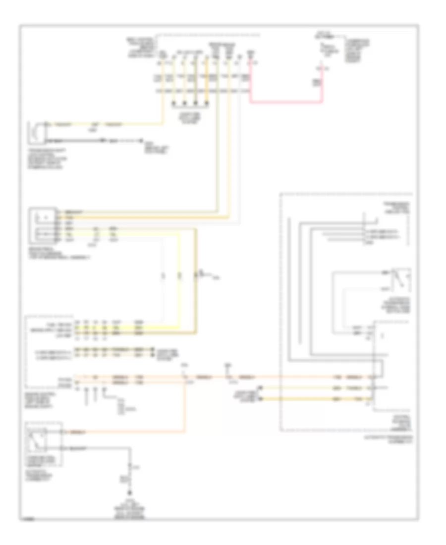
Backup Lamps Wiring Diagram for GMC RV Cutaway G2013 3500
List of elements for Backup Lamps Wiring Diagram for GMC RV Cutaway G2013 3500:
- (4.8l, 5.3l & 6.0l: on right rear of engine) (6.6l: left front lower side of the engine block) (4.3l: left rear of engine) g103
- (provisional)
- All times
- Automatic transmission
- Automatic transmission assembly (6 speed a/t)
- Automatic transmission internal mode switch (ims)
- Aux/trlr bck/up fuse 10a
- Backup alarm (rear of vehicle on frame)
- Bck/up lamp pcb relay k7
- Body control module (bcm) (behind lower right side of dash)
- Body fuse block (under left front seat)
- Bus - data
- Computer data lines system
- Control solenoid valve assembly
- Cutaway
- D3 x3
- Data bus +
- Data bus - x3
- G302 (behind left kick panel)
- G400 (on inner left rear frame rail)
- G401 (on top of right "d" pillar)
- G402 (on top of left left "d" pillar)
- Gmlan hi spd
- Gnd
- H x405
- Hi spd gmlan data bus +
- Hi spd gmlan serial data bus (+)
- Hi spd gmlan serial data bus (-)
- Hot at
- J101
- J247
- J402
- J403
- J410
- Left backup lamp (cargo/ passenger)
- Left tail/ stop & turn signal lamp
- Mega fuse 125a
- Nca
- Park/neutral position (pnp) switch
- Power distribution system
- Red
- Relay ctrl x2
- Right backup lamp (cargo/ passenger)
- Right tail/ stop & turn signal lamp
- Sig a
- Sig b
- Sig c
- Tail lamp bck/up fuse 10a
- Tan
- Trailer connector (if equipped)
- Trans rng sw sig a
- Trans rng sw sig b
- Trans- mission control module (tcm)
- Transmission control module (tcm) (left front corner of engine compt)
- Underhood fuse block (on left side of engine compt)
- W/ electrical backup alarm
- X1 e2
- X1 j5
- X175
- X401
- X401 f
- X402
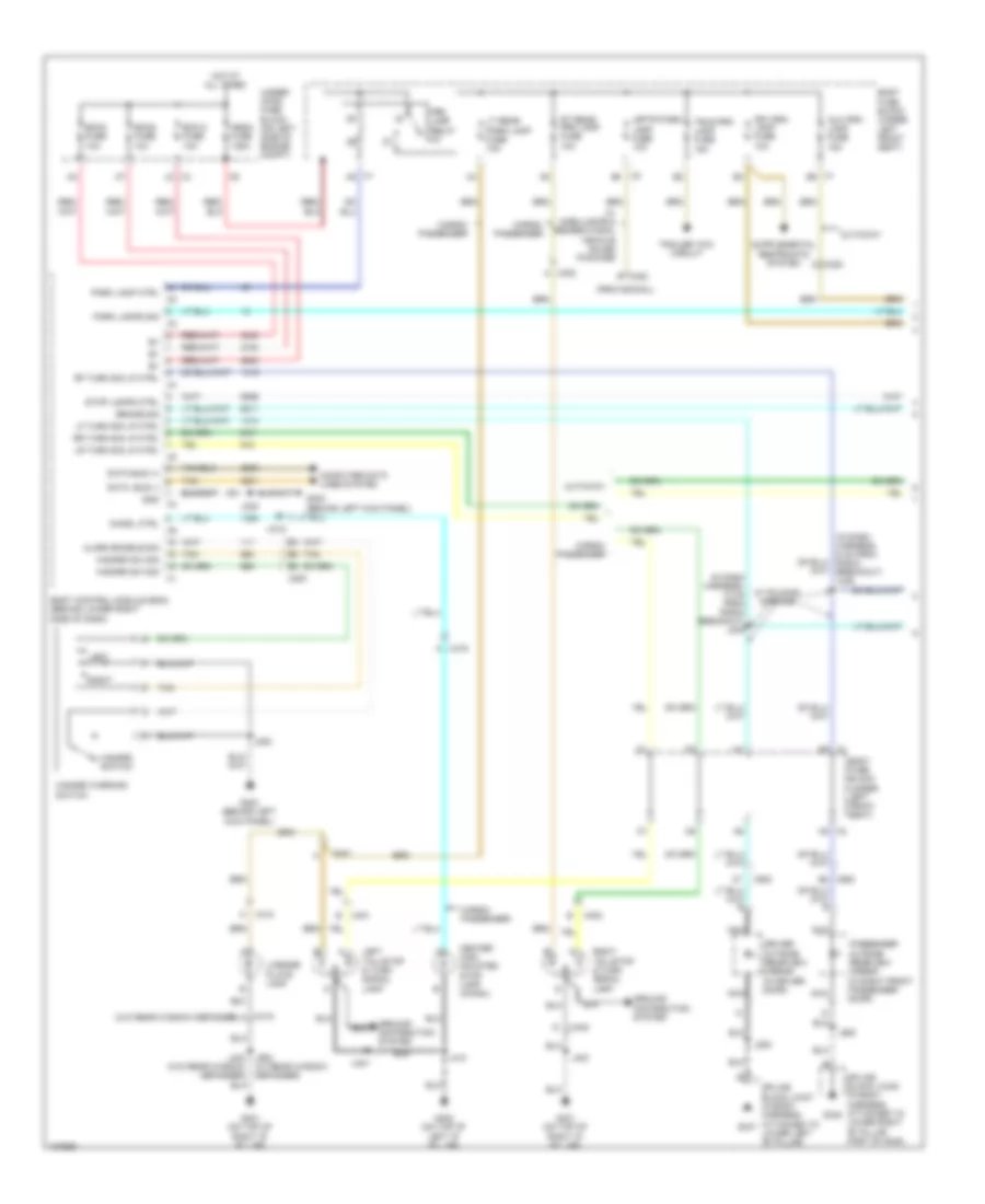
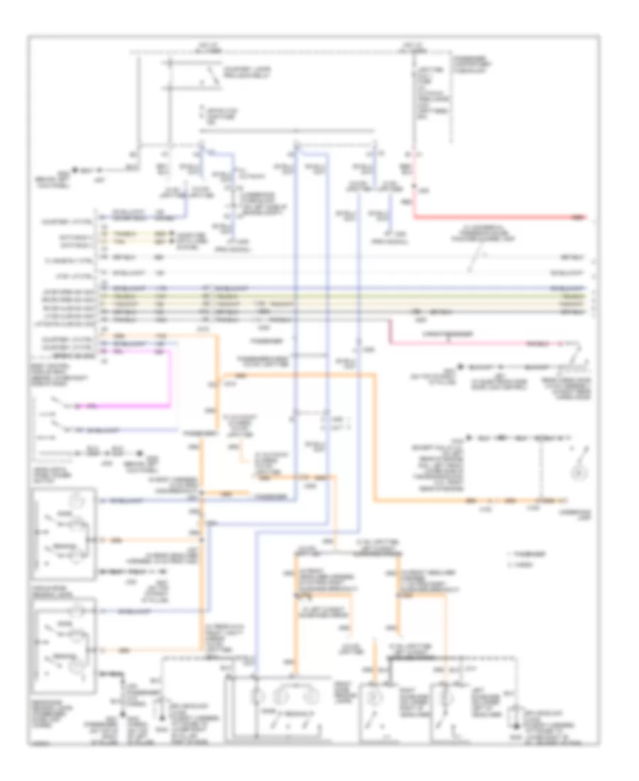
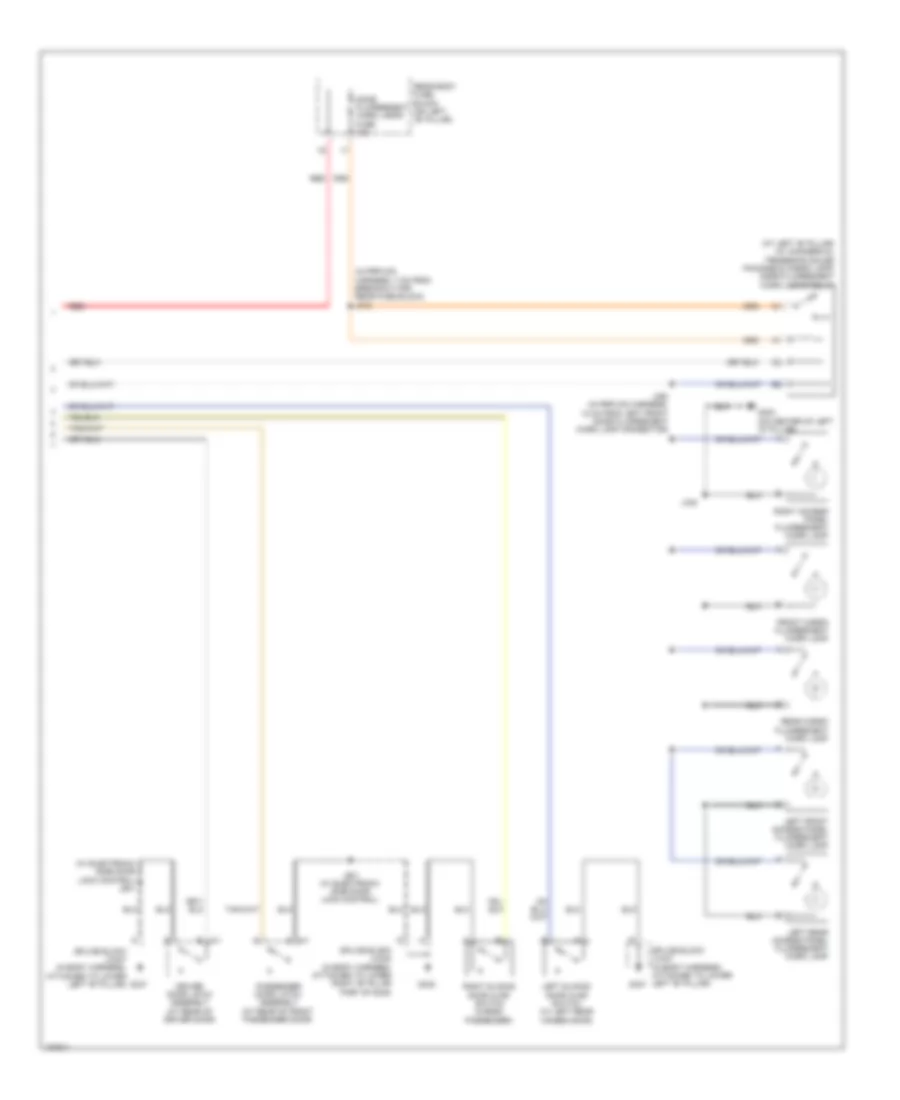
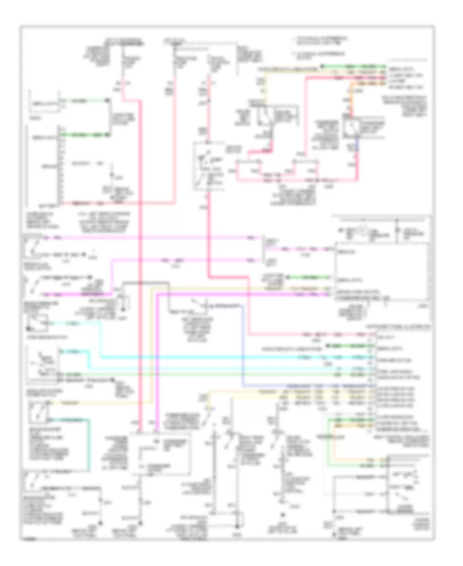
Exterior Lamps Wiring Diagram (1 of 2) for GMC RV Cutaway G2013 3500
List of elements for Exterior Lamps Wiring Diagram (1 of 2) for GMC RV Cutaway G2013 3500:
- (in dash harness, 13 cm from radio breakout) j245
- (in dash harness, 6 cm from radio breakout) j246
- (provisional)
- A x419
- Alarm enable sig
- Aux prk lamp fuse 15a
- B3 x600
- Bcm 6 fuse 10a
- Bcm3 fuse 10a
- Bcm5 fuse 10a
- Body control module (bcm) (behind lower right side of dash)
- Body fuse block (under left front seat)
- Brake sig
- Cargo/ passenger
- Center high mounted stop lamp (chmsl)
- Chmsl ctrl
- Computer data lines system
- Cutaway
- Data bus (-)
- Data bus (+)
- Driver outside rearview mirror (in driver door)
- Frt prk lamp fuse 10a
- G302 (behind left kick panel)
- G347
- G348
- G401 (on top of right "d" pillar)
- G402 (on top of left "d" pillar)
- Gnd
- Ground distribution system
- Hazard sw sig
- Hazard switch
- Hazard warning switch
- Hot at all times
- J202
- J248
- J403
- J403 (w/o rear window defogger)
- J410
- J500
- J600
- J902 (w/ rear window defogger)
- Left
- Left tail/stop & turn signal lamp
- Lf turn sig lp ctrl
- License plate lamp
- Lr turn sig lp ctrl
- Lt rear park lamp fuse 10a
- Mega fuse 125a
- Nca
- Park lamp ctrl
- Park lamps sig
- Passenger outside rearview mirror (in right front passenger door)
- Prk lamp relay k3
- Rf turn sig lp ctrl
- Right
- Right tail/stop & turn signal lamp
- Rr turn sig lp ctrl
- Rt rear prk lamp fuse 10a
- Splice block jx347 (in body harness, attached to lower left "b" pillar)
- Splice block jx348 (in body harness, attached to lower right "b" pillar part of g348)
- Stop lamps ctrl
- Tan
- Trailer tow circuit
- Trlr prk lamp fuse 15a
- Under- hood fuse block (on left side of engine compt)
- Upftr park lamp fuse 10a
- W/ ambulance & recreational vehicle sales package
- W/ folding mirrors
- X1 a5
- X1 b5
- X1 g3
- X2 b4
- X200
- X3 j2
- X318
- X320
- X320 x
- X401
- X402
- X402 a
- X412
- X412 c (w/o rear window defogger)
- X500
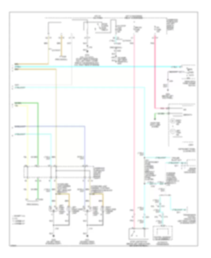
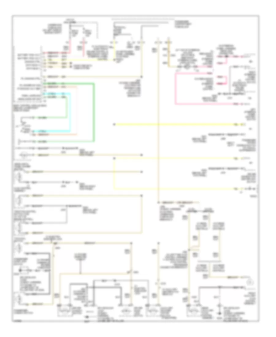
Exterior Lamps Wiring Diagram (2 of 2) for GMC RV Cutaway G2013 3500
List of elements for Exterior Lamps Wiring Diagram (2 of 2) for GMC RV Cutaway G2013 3500:
- (in engine harness, 16 cm from underhood fuse block x1 breakout) j123
- (in forward lamp harness, 48 cm from left headlamp breakout) j121
- (on inner left rear frame rail) g400
- (provisional)
- 4 speed a/t
- 4.3l
- 6 speed a/t
- 6.6l
- A x221
- A5 x101
- Auto
- Automatic transmission
- Aux stop lamp fuse 15a
- Brk sw fuse 10a
- Computer data lines system
- Control solenoid valve assembly
- Cutaway
- E x405
- Engine control module (ecm)
- Except 4.3l
- G100 (on left front of engine compt)
- G101 (on right front of engine compt)
- G102 (4.8l, 5.3l & 6.0l: on left rear of engine) (6.6l: left front lower side of the engine block) (4.3l: right rear of engine)
- G302 (behind left kick panel)
- Head
- Headlamp & panel dimmer switch
- Hot at all times
- Hot w/ run/crank relay 15 energized
- Ign
- Instrument panel cluster (ipc)
- Ipc fuse 10a
- J100
- J102
- J110
- J231 (in instrument panel harness, 5 cm from x200 breakout towards instrument panel cluster)
- J248
- J402
- Left front side marker lamp
- Left park/ turn signal lamp
- Left turn ind
- Logic
- N x174
- Off
- Park
- Pnk
- Right front side marker lamp
- Right park/ turn signal lamp
- Right turn ind
- Ser data
- Stop lamp switch (behind left side of dash, above brake pedal)
- Stop lamps pcb relay
- Transmission control module (tcm) (left front corner of engine compt)
- Underhood fuse block (on left side of engine compt)
- X1 c7
- X100
- X2 a4
- X2 e2
- X2 f3
- X3 a1
- X3 c5
- X3 h7
- X3 j4
- X4 c
- X405 c
- X405 f
- X405 g
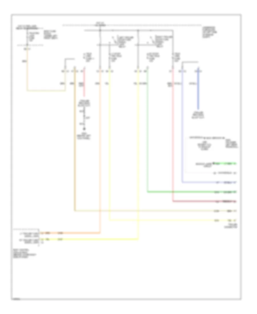
Trailer Tow Wiring Diagram for GMC RV Cutaway G2013 3500
List of elements for Trailer Tow Wiring Diagram for GMC RV Cutaway G2013 3500:
- Backup lamps circuit
- Body control module (bcm) (behind lower right side of dash)
- Body fuse block (under left front seat)
- G302 (behind left kick panel)
- G400 (on inner left rear frame rail)
- Hot at all times
- Hot w/ prk lamp relay k3 energized
- J247
- J460 (except 5.3l w/ backup alarm)
- Left trailer stop/turn signal lamp relay
- Lt stop/ trn trlr fuse 10a
- Lt trailer turn signal lamp
- Right trailer stop/turn signal lamp relay
- Rt stop/ trn trlr fuse 10a
- Rt trailer turn signal lamp
- Trailer connector
- Trlr prk lamp fuse 15a
- Trlr wrg fuse 11 30a
- Trlr wrg fuse 30a
- Underhood fuse block (on left side of engine compt)
- X1 b2
- X2 a7
- X2 e3
- X2 e4
- X3 b5
- X3 c4
- X3 d4
- X3 g3
GROUND DISTRIBUTION
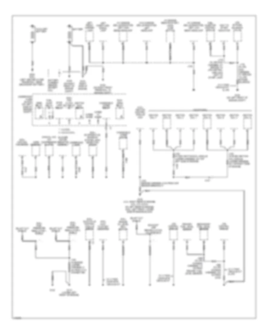
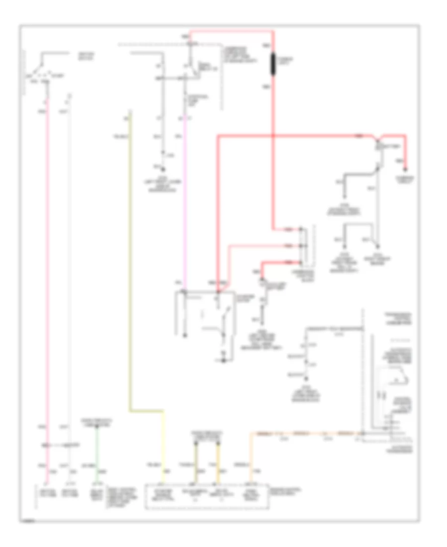
Ground Distribution Wiring Diagram (1 of 5) for GMC RV Cutaway G2013 3500
List of elements for Ground Distribution Wiring Diagram (1 of 5) for GMC RV Cutaway G2013 3500:
- (4.3l) ignition control module (icm)
- (6.6l) cooling fan motor
- (6.6l) engine oil level (eol) switch
- (6.6l) evaporative emission system leak detection pump
- (6.6l) fan cltch (ev) relay
- (6.6l) fuel pressure regulator 1 shield
- (6.6l) fuel pressure regulator 2 shield
- (6.6l) glow plug control module (gpcm)
- (6.6l) wait to start indicator
- (in odd ignition/coil module jumper harness, on top left side of engine)
- (manual a/c) a/c compressor clutch
- (w/ chrome grille radiator) left high beam headlamp
- (w/ chrome grille radiator) left low beam headlamp
- (w/ engine remote start) hood ajar switch
- (w/o chrome grille radiator) left headlamp
- 4.3l/6.6l
- 4.8l/5.3l/6.0l
- Auxiliary battery
- Battery
- Battery current sensor (except 6.6l)
- Blower motor resistor assembly
- Crnk relay
- Exhaust gas recirculation valve shield
- Fuel injector control module
- Fuel pump relay
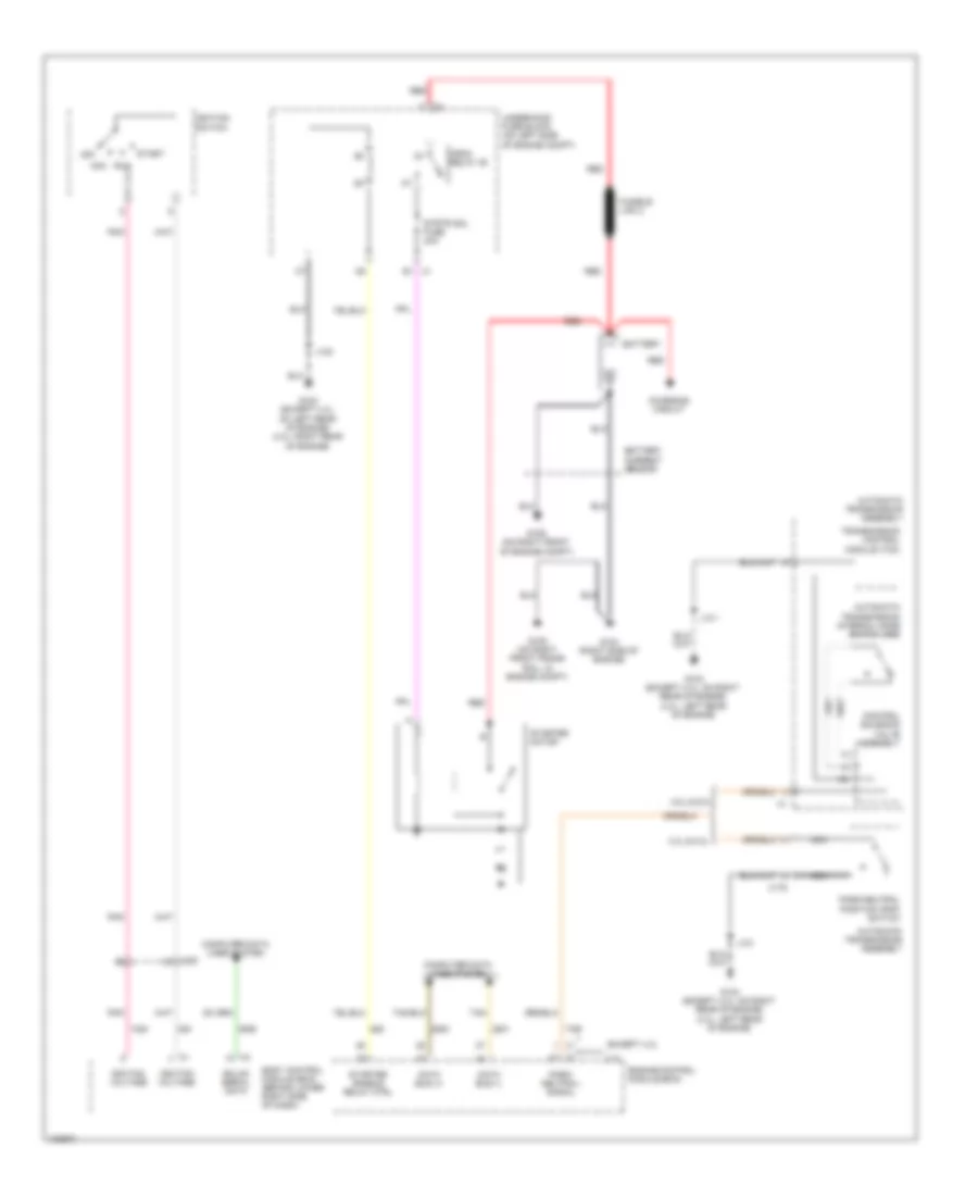
- G100 (on left front of engine compt)
- G102 (4.3l: right rear of engine) (4.8l, 5.3l & 6.0l: on left rear of engine) (6.6l: left front lower side of engine block)
- G104 (right side of engine)
- G105 (on right front frame rail, in engine compt)
- G106 (on right front of engine compt)
- G110 (lower left front of engine)
- G120
- G305 (6.6l) (left center outer frame rail, near secondary battery)
- Horn assembly
- Ignition coil 1
- Ignition coil 2
- Ignition coil 3
- Ignition coil 4
- Ignition coil 5
- Ignition coil 6
- Ignition coil 7
- Ignition coil 8
- Ignition run relay
- J100
- J102 (engine harness, 6 cm from map sensor breakout)
- J176
- J179 (in lpg main harness, at ground to lpg control module & wait to start lamp)
- J183 (in even ignition/ coil module jumper harness, on top right side of engine)
- J369 (in lpg chassis harness, 7.5 cm from primary fuel level sensor)
- Jumper harness, 9 cm from x110 connector)
- Left front marker lamp
- Left park/turn signal lamp
- Lpg bypass solenoid valve
- Lpg control module
- Nca
- Primary fuel level sensor
- Run/ crnk relay
- Secondary fuel level sensor
- Stop lamp relay
- Underhood fuse block (on left side of engine compt)
- Underhood lamp
- W/ 3 tank vehicle kit & lpg
- W/ 4 tank complete vehicle kit
- W/ 4 tank vehicle kit & lpg
- Wait to start indicator
- Windshield wiper motor
- Windshield wiper relay
- Wiper diode
- Wiper hi diode
- X100
- X109
- X126
- X127
- X142
Ground Distribution Wiring Diagram (2 of 5) for GMC RV Cutaway G2013 3500
List of elements for Ground Distribution Wiring Diagram (2 of 5) for GMC RV Cutaway G2013 3500:
- (4 speed a/t) automatic transmission assembly
- (4 speed a/t) transmission control module (tcm)
- (6 speed a/t) automatic transmission assembly
- (6.6l) multi- function intake air sensor
- (except 6.6l) engine control module (ecm)
- (except 6.6l) mass air flow (maf)/ intake air temperature (iat) sensor
- (heavy duty) brake fluid level switch
- (if equipped) backup alarm
- (in lpg chassis harness, 30.5 cm from primary liquid propane delivery module)
- (not used) g
- (w/ dedicated cng) cng control module
- 4.3l/ 5.3l
- 4.8l & 6.0l
- 4.8l, 6.ol, 4.3l w/o hd truck trailer
- 5.3l w/ hd truck trailer w/o backup alarm
- 6.6l
- Body control module (bcm)
- C10
- Control solenoid valve assembly
- Coolant heater
- Coolant heater fuel pump
- Engine control module (ecm)
- Except 5.3l w/ hd truck trailer
- Except 5.3l w/ hd truck trailer & backup alarm
- Exhaust gas recirculation (egr) valve shield
- Fuel compo- sition sensor
- Fuel cut off solenoid valve
- Fuel filter pressure switch
- Fuel heater
- Fuel pressure regulator 1 shield
- Fuel pressure regulator 2 shield
- Fuel pump
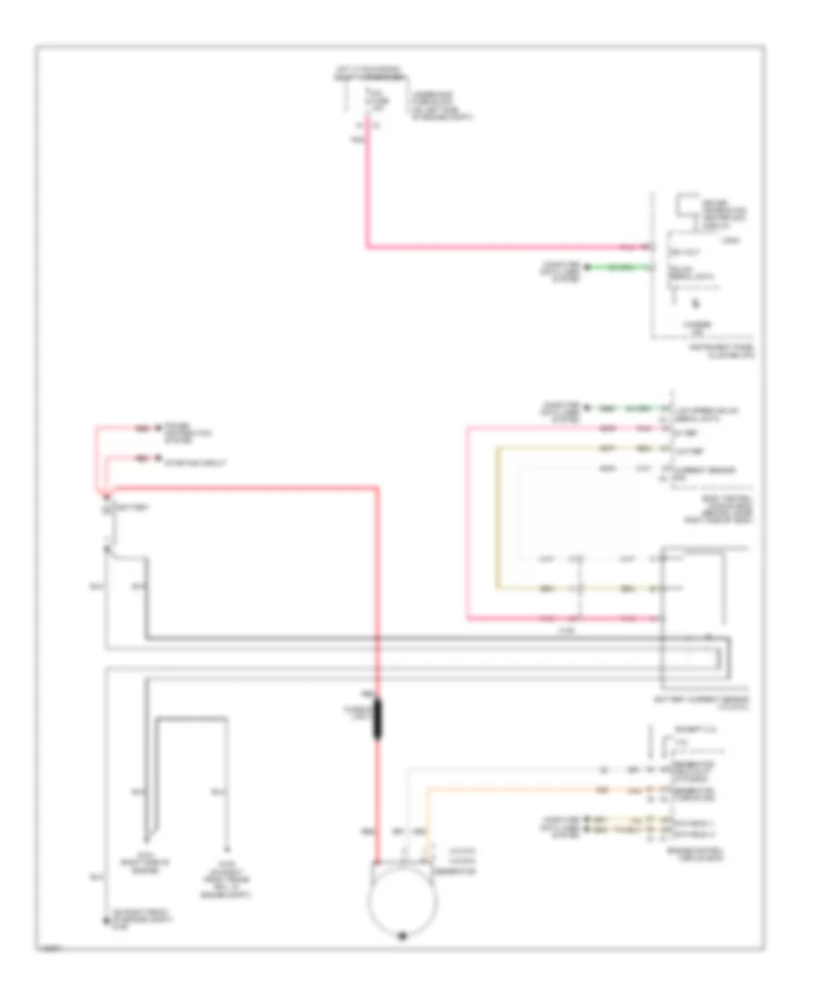
- Fuel pump & level sensor assembly
- G103 (4.3l: left rear of engine) (4.8l, 5.3l & 6.0l: on right rear of engine) (6.6l: left front lower side of engine block)
- G109 (6.6l) (lower right front of engine)
- G350 (rear of transmission case)
- G400 (on inner left rear frame rail)
- Glow plug control module (gpcm)
- H x1
- Intake air valve shield
- J160 (in engine harness, 5.5 cm from x110 breakout)
- J161 (in engine harness, 6.5 cm from engine control module x2 connector breakout)
- J162 (in engine harness, 10 cm from g109 breakout)
- J163 (in engine harness, 23 cm from g109 breakout)
- J316 (in transmission harness, 20 cm (7.87 in) from x174)
- J402 (cutaway: in chassis harness, 24 cm from g400 breakout) (passenger/cargo: in chassis harness, 16 cm from g400 breakout)
- J430 (in lpg fuel tank harness, 1778mm from x350) x350
- Nca
- Park/ neutral position (pnp) switch
- Primary lpg pump assembly
- Reductant line heater
- Reductant pump
- Reductant sensor module
- Reductant tank heater
- Secondary lpg pump assembly
- Trailer connector b
- W/ 3 tank complete vehicle kit & lpg
- W/ 4 tank complete vehicle kit
- W/ cargo 6.6l, except 5.3l w/ hd truck trailer & backup alarm
- W/ dedicated cng
- W/ fuel fired auxiliary heater
- W/o dedicated cng
- X1 (4.8l/ 5.3l/ 6.0l)
- X101
- X174
- X2 (4.3l)
- X305
- X316
- X350
- X395
- X405
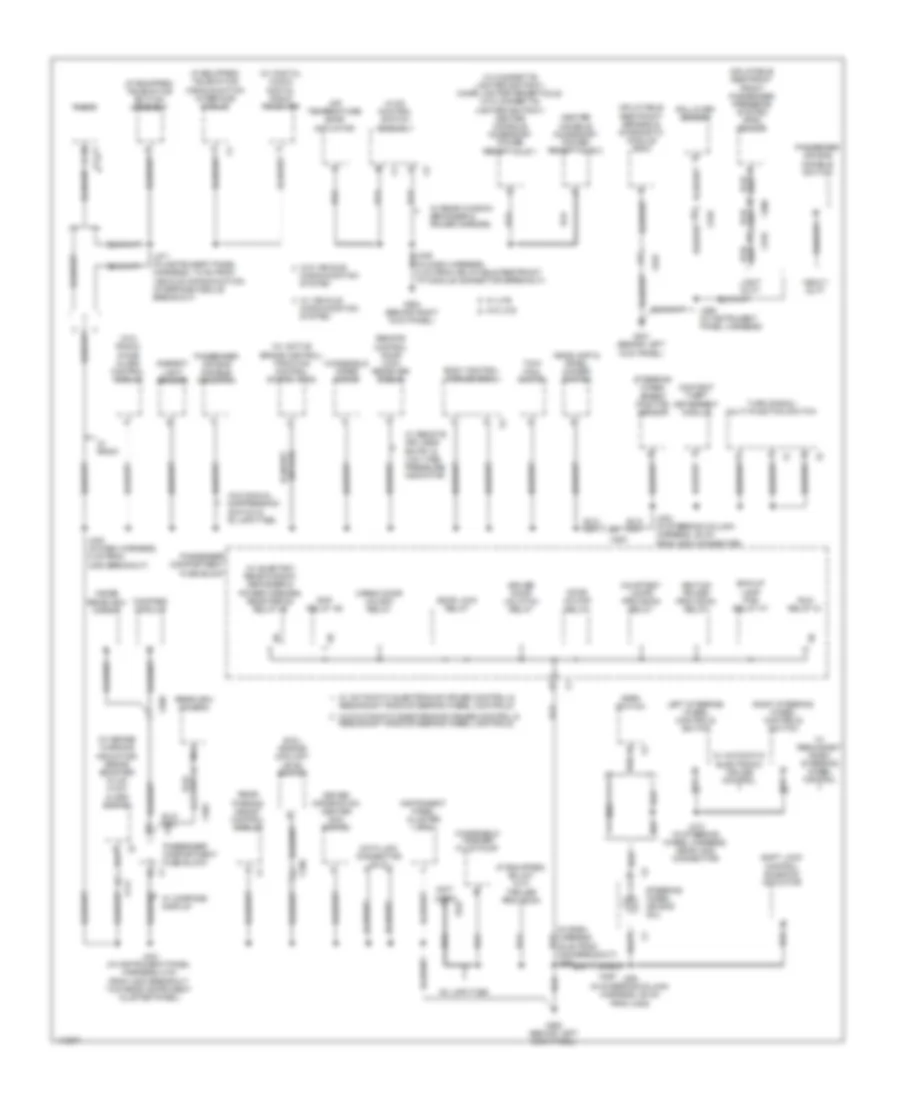
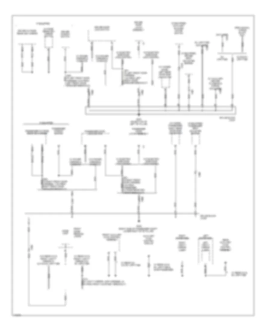
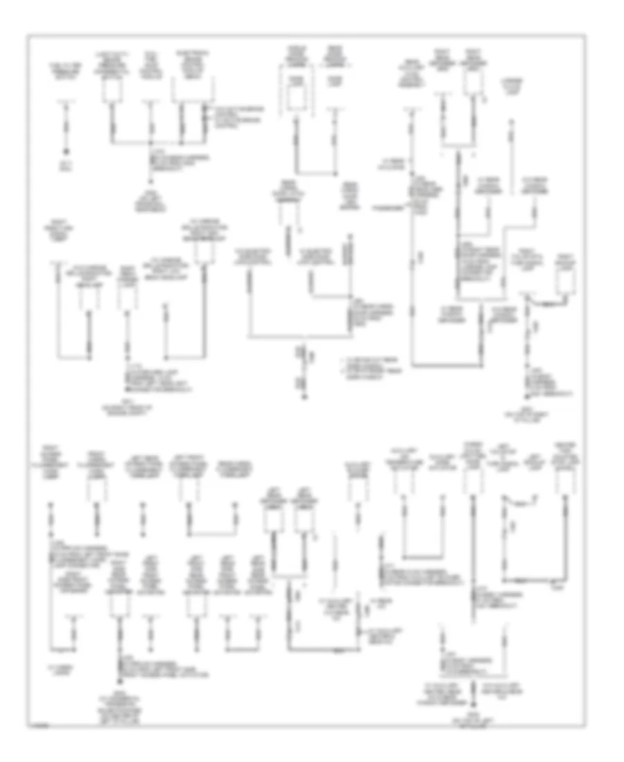
Ground Distribution Wiring Diagram (3 of 5) for GMC RV Cutaway G2013 3500
List of elements for Ground Distribution Wiring Diagram (3 of 5) for GMC RV Cutaway G2013 3500:
- (6.6l) engine coolant level switch
- (if equipped) telematics button assembly
- (if equipped) telematics communication interface module
- (in dash harness, 36 cm from x200 breakout) j247
- (in dash harness, 5 cm from inflatable restraint i/p module connector breakout)
- (not used) c
- (w/ active brake control) traction control switch (tcs)
- (w/ brake warning indicator) brake booster fluid flow alarm switch
- (w/ cigarette lighter ashtray) cigar lighter receptacle (w/o cigarette lighter ashtray) center console accessory power receptacle 1
- (w/ digital audio) digital radio receiver
- (w/ electric rear window defogger & power mirrors) rear defog relay k5
- (w/o radio) chime alarm control module
- Air temperature door actuator
- Ambient light sensor
- Bck/up lamp pcb relay k7
- Body control module (bcm)
- Cargo door unlock relay
- Center console accessory power receptacle 2
- Communication system
- Compass module
- Content theft deterrent module
- Courtesy lamps provision relay
- Data link connector (dlc)
- Door lock relay
- Door unlock relay
- Driver door unlatch relay
- Driver information center (dic) switch
- G301 (behind left kick panel)
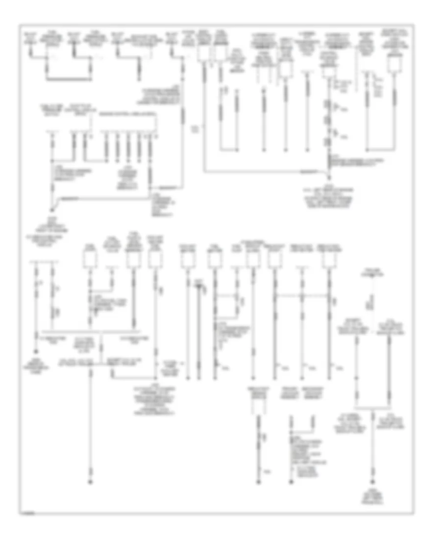
- G302 (behind left kick panel)
- G304 (behind right kick panel)
- Headlamp & panel dimmer switch
- Heavy duty
- Horn switch
- Hvac control switch assembly
- Ignition power provision relay
- Inflatable restraint front passenger presence system (pps) sensor
- Inflatable restraint sensing & diagnostic module (sdm)
- Inside rearview mirror
- Instrument panel cluster (ipc)
- J202 (in steering column harness, 25 cm from x200 connector)
- J210 (in steering wheel harness, near x200 connector)
- J244 (in instrument panel harness, 5 cm from x200 breakout towards instrument cluster panel)
- J248 (in dash harness, 8 cm from x200 breakout)
- J264 (in steering column harness, 29 cm from x200)
- J265 (in instrument panel harness)
- J271 (in instrument panel harness, 7.5 cm from vehicle communication interface module breakout)
- Left steering wheel controls switch
- Nca
- Passenger air bag disable indicator
- Passenger air bag disable switch
- Passenger compartment fuse block
- Radio
- Rap relay k6
- Rear parking assist control module
- Rearview camera
- Redundant radio steering wheel controls
- Remote control door lock receiver (rcdlr)
- Right steering wheel controls switch
- Rollover sensor
- Run relay k1
- Rv upfitter
- Shift lock control solenoid actuator
- Steering wheel air bag coil
- Steering wheel speed/ position sensor
- Tow/ haul switch
- Turn signal/ multi-function switch
- W/ automatic electronic cruise control
- W/ automatic electronics cruise control &
- W/ compass display
- W/ radio
- W/ rear window defogger & power mirrors
- W/ redundant radio steering wheel control
- W/ remote keyless entry & low tire pressure indicator
- W/ uys
- W/ vehicle
- W/o automatic electronics cruise control &
- W/o manual suppression switch & rv upfitter
- W/o uys
- W/o vehicle
- Windshield washer fluid pump
- Windshield wiper motor
- X100
- X141
- X2 passenger compartment fuse block
- X200
- X205
- X222
- X306
- X318
- X403
Ground Distribution Wiring Diagram (4 of 5) for GMC RV Cutaway G2013 3500
List of elements for Ground Distribution Wiring Diagram (4 of 5) for GMC RV Cutaway G2013 3500:
- (if equipped) auxiliary blower motor switch
- (if equipped) driver seat adjuster switch
- (if equipped) passenger seat adjuster switch
- (not used) c
- (w/ auxiliary heater plumbing & wiring) (not used) b
- (w/ cargo passenger) right rear door side jam switch
- (w/ hinged door) left rear door side jam switch
- Auxiliary hvac control module
- Cm from front courtesy breakout)
- Cutaway upfitter
- Dome lamp
- Driver door latch assembly
- Driver door lock switch
- Driver outside rearview mirror
- Driver window switch
- E x319
- Front auxiliary hvac control assembly
- Front dome/ reading lamps
- G347 (on bottom of left "b" pillar)
- G348 (right side of passenger compt, lower right of "b" pillar)
- If equipped
- J500 (in left front door harness, 6 cm from left front door speaker breakout)
- J501 (in left front door harness, 7 cm from left front door speaker breakout)
- J600 (in right front door harness, 7 cm from right front door speaker breakout)
- J601 (in right front door harness, 5 cm from passenger outside rearview mirror breakout)
- Left sunshade
- Left vanity mirror lamp
- Nca
- Outside rearview mirror switch
- Passenger door latch assembly
- Passenger door lock switch
- Passenger outside rearview mirror
- Passenger window switch
- Rear auxiliary hvac control assembly
- Right sunshade
- Right vanity mirror lamp
- Rv upfitter
- Rv upfitter (not used) p
- Splice block jx347
- Splice block jx348
- W/ electric side door lock control
- W/ power mirrors & windows
- W/ rear a/c & front vanity mirror w/o rv upfitter
- W/ rear a/c & rv upfitter
- W/ rear a/c & rv upfitter & swb passenger
- W/ rear a/c w/o rv upfitter
- W/o electric side door lock control
- W/o power mirrors & windows
- W/o rear a/c & front vanity mirror w/ cutaway upfitter
- X205
- X306
- X307
- X320
- X321
- X409
- X500
- X600
Ground Distribution Wiring Diagram (5 of 5) for GMC RV Cutaway G2013 3500
List of elements for Ground Distribution Wiring Diagram (5 of 5) for GMC RV Cutaway G2013 3500:
- (5.3l) fuel pump control module
- (cargo w/o rv upfitter) dome lamp
- (light duty) brake pressure differential switch
- (w/ chrome grille radiator) right high beam headlamp
- (w/ chrome grille radiator) right low beam headlamp
- (w/o chrome grille radiator) right headlamp
- Auxiliary air temperature actuator
- Auxiliary blower motor
- Auxiliary mode actuator
- B x409
- Center high mounted stop lamp (chmsl)
- Dome lamp
- Door window
- Door window w/ stationary rear
- Electronic brake control module (ebcm)
- Front cargo fluorescent work lamp
- Fuel filter pressure switch
- G101 (on right front of engine compt)
- G111 (6.6l)
- G300 (on left frame rail, near ebcm)
- G401 (on top of right "d" pillar)
- G402 (on top of left "d" pillar)
- G403 (w/ commercial tradesman sales package) (on center of left "d" pillar)
- J110 (in forward lamp harness, 12 cm from left headlight connector breakout)
- J300 (in prp/uf2 harness, 42 cm from left front side front access panel actuator)
- J315 (in chassis harness, 10 cm from g300 breakout)
- J330 (in rear headliner harness, 30 cm from x420)
- J403 (in body harness, 6 cm from g401 breakout)
- J410 (in body harness, 47 cm from x401 breakout)
- J411 (in rear hvac harness, 6 cm from auxiliary blower motor connector breakout)
- J901 (in rear cargo door harness, 35 cm from x902)
- J902 (in right rear door harness, 19 cm from license lamp connector breakout)
- Left backup lamp
- Left front access panel fluorescent work lamp
- Left front side front access panel actuator
- Left front side rear access panel actuator
- Left rear access panel fluorescent work lamp
- Left rear defogger grid
- Left rear side front access panel actuator
- Left rear side rear access panel actuator
- Left tail/stop & turn signal lamp
- License plate lamp
- Middle dome/ reading lamps
- Nca
- Passenger
- Rear auxiliary hvac control assembly
- Rear cargo door latch assembly
- Rear cargo door lock switch
- Rear cargo fluorescent work lamp
- Rear dome/ reading lamps
- Right access panel fluorescent work lamp
- Right backup lamp
- Right front marker lamp
- Right park/turn signal lamp
- Right rear defogger grid
- Right side front access panel actuator
- Right side rear access panel actuator
- Right tail/stop & turn signal lamp
- W/ auxiliary heater & rear a/c
- W/ auxiliary heater w/o rear a/c
- W/ auxiliary heater, rear a/c & rear window defogger
- W/ cargo lamps
- W/ electric side door lock control
- W/ rear a/c
- W/ rear a/c & swb
- W/ rear window defogger
- W/ swing out rear
- W/o active brake control w/ active brake control
- W/o auxiliary heater & rear a/c
- W/o electric side door lock control
- W/o rear window defogger
- X400
- X401
- X402
- X409
- X411
- X412
- X420
- X901
- X902
HEADLIGHTS
Headlights Wiring Diagram for GMC RV Cutaway G2013 3500
List of elements for Headlights Wiring Diagram for GMC RV Cutaway G2013 3500:
- (behind left kick panel) g302
- Ambient light sensor (on top of instrument panel)
- Ambient sens sig
- Auto
- Body control module (bcm) (behind lower right side of dash)
- Computer data lines system
- Drl 1 fuse 67 15a
- Drl 2 fuse 66 10a
- Drl pcb relay k19
- Ftp
- Fusible link 2
- G100 (on left front of engine compt)
- G101 (on right front of engine compt)
- G302 (behind left kick panel)
- Gnd
- Head
- Head lamp high beam relay
- Headlamp & panel dimmer switch
- Headlamp lo sig
- Headlamp sw sig
- Hi beam rly ctrl
- High beam ind
- Hot at all times
- Hot w/ run/crnk relay 15 energized
- Ign
- Instrument panel cluster (ipc)
- Ipc fuse 10 10a
- J100
- J110
- J202
- J248
- Left headlamp
- Left high beam headlamp
- Left low beam headlamp
- Lo beam ctrl
- Lo beam rly ctrl
- Logic
- Low
- Low beam pcb relay k6
- Lt hi beam fuse 51 10a
- Lt lo beam fuse 53 10a
- Off
- Park
- Park brake switch (under left side of dash)
- Park brk sw sig
- Park lamps sig
- Pnk
- Red
- Right headlamp
- Right high beam headlamp
- Right low beam headlamp
- Rt hi beam fuse 52 10a
- Rt lo beam fuse 54 10a
- Serial data
- Switch off sig
- Switch on sig
- Turn signal/ multi-function switch
- Underhood fuse block (on left side of engine compt)
- W/ chrome grille
- W/o chrome grille
- X200
- X220
HORN
Horn Wiring Diagram for GMC RV Cutaway G2013 3500
List of elements for Horn Wiring Diagram for GMC RV Cutaway G2013 3500:
- (w/ automatic electronics cruise control & redundant radio steering wheel controls) j210
- A x1
- A1 x200
- Body control module (bcm) (behind lower right side of dash)
- G102 (4.3l: right rear of engine) (4.8l, 5.3l & 6.0l: on left rear of engine) (6.6l: left front lower side of engine block)
- G302 (behind left kick panel)
- Horn assembly (at left front of engine compt)
- Horn fuse 16 20a
- Horn relay ctrl
- Horn switch (in steering wheel)
- Horn/ wash pcb relay k5
- Hot at all times
- Inflatable restraint steering wheel module coil (at top of steering column)
- J102
- J264
- Tan
- Underhood fuse block (on left side of engine compt)
- X1 a
- X1 b4
- X2 a
- X2 k
INSTRUMENT CLUSTER
Instrument Cluster Wiring Diagram (1 of 3) for GMC RV Cutaway G2013 3500
List of elements for Instrument Cluster Wiring Diagram (1 of 3) for GMC RV Cutaway G2013 3500:
- (if equipped) electronic compass module
- Abs ind
- Air bag ind
- Ajar sw sig
- Ambient air temperature sensor (w/ outside temperature display) (behind front grille, on radiator support)
- B11
- Batt pos volt
- Belt ind
- Body control module (bcm) (behind lower right side of dash)
- Body fuse block (under left front seat)
- Brake ind
- Charge ind
- Cmps fuse 19 10a
- Computer data lines system
- Cruise ind
- Dic sw sig
- Driver information center (dic) display
- Engine controls system
- Engine coolant level switch (6.6l) (right front of engine compt, attached to bottom of coolant surge tank)
- Engine coolant temperature gauge
- Fuel gauge
- G302 (behind left kick panel)
- Gmlan serial
- Gnd
- High beam ind
- Hot at all times
- Hot w/ run relay k1 energized
- Hot w/ run/crank relay 15 energized
- Ign volt
- Ind ctrl
- Ind lamp (mil) malfunction
- Instrument panel cluster (ipc)
- Ip cluster fuse 23 10a
- Ipc fuse 10 10a
- J244
- Left turn ind
- Lf door ajar sw
- Liftgate
- Logic
- Low engine oil pressure gauge
- Low fuel ind
- Low ref
- Low stability ind
- Lr door open sw
- Mil ctrl
- Network 3
- Odometer
- Park brake switch (under left side of dash)
- Pass off ind
- Pass on ind
- Pass seat belt
- Passenger seat
- Pnk
- Pressure ind low oil
- Prnd 321
- Rf door ajar sw
- Right turn ind
- Rr door open sw
- Seat belt ind
- Security ind
- Sens sig
- Seo fuse 27 10a
- Speedometer
- Sw sig
- Switch sig
- Tire pressure ind
- Tow/haul ind
- Traction control ind
- Underhood fuse block (on left side of engine compt)
- Volts gauge
- W/ brake warning indicator system
- W/ odometer security wiring provision (seo)
- W/o odometer security wiring provision (seo)
- Wait to start ind (diesel)
- X100
- X150
- X205
- X220
- X318
Instrument Cluster Wiring Diagram (2 of 3) for GMC RV Cutaway G2013 3500
List of elements for Instrument Cluster Wiring Diagram (2 of 3) for GMC RV Cutaway G2013 3500:
- (or 6049)
- 4.3l
- 4.8l/5.3l/6.0l
- 5v ref 2
- 6.6l
- C12
- Cargo door latch assembly (w/ cargo/passenger) (in right rear cargo door)
- Computer data lines system
- Data bus(+)
- Data bus(-)
- Driver door latch assembly (at rear of driver door)
- Driver information center (dic) switch
- Engine control module (ecm) (left side of engine compt)
- G302 (behind left kick panel)
- G347
- G348
- G401 (on top of right "d" pillar)
- Hinged door)
- Illumi- nation
- Interior lights system
- J244
- J501 (w/ electronic side door lock control))
- J601 (w/ electronic side door lock control)
- J901 (w/ electronic side door lock control)
- Left sliding door ajar switch (w/ left rear
- Low ref
- Passenger door latch assembly (at rear of front passenger door)
- Person- alization
- Pnk
- Right sliding door ajar switch (w/ cargo/passenger)
- Sens sig
- Set/ reset
- Splice pack jx347 (in body harness, attached to lower left "b" pillar)
- Splice pack jx348 (in body harness, attached to lower right "b" pillar part of g348)
- Switch sig
- Tan
- Trip/ fuel
- Vehicle info
- W/ brake warning indicator system
- Water in fuel sensor
- X101
- X107
- X174
- X316 b
- X318
- X400
- X500
- X600
Instrument Cluster Wiring Diagram (3 of 3) for GMC RV Cutaway G2013 3500
List of elements for Instrument Cluster Wiring Diagram (3 of 3) for GMC RV Cutaway G2013 3500:
- 4.3l
- 4.3l, 4.8l & 6.0l (vin g)
- 4.8l/5.3l/6.0l
- 5.3l
- 5v ref
- 6.0l (vin b)
- 6.6l
- Alternative fuel tank pressure sensor
- B x141
- B4 x101
- Brake booster fluid flow alarm switch (in power steering pump outlet hose)
- Brake booster fluid pressure alarm switch (in power steering pump inlet hose)
- Brake pressure differential switch (on brake valve, near front of ebcm)
- Cng control module (6.0l(vin b)) (forward of left rear spring on frame)
- Cng fuel vehicle
- Compt)
- Engine controls system
- Engine oil level switch (on left side of oil pan)
- Engine oil pressure (eop) sensor (except 6.6l: on top rear of engine) (6.6l: lower left side of engine)
- Fuel level sensor (on fuel tank)
- Fuel pump & sender assembly (on fuel tank)
- Fuel pump relay sig
- G103 (4.3l: left rear of engine) (6.6l: left front lower side of engine block) (4.8l, 5.3l & 6.0l: on right rear of engine)
- G110 (lower left front of engine)
- G300 (on left frame rail, near ebcm)
- G302 (behind left kick panel)
- Heavy duty
- J101
- J244
- J301 (cutaway: in chassis harness, 87 cm from ebcm connector breakout) (passenger/cargo: in chassis harness, 44 cm from ebcm connector breakout)
- J315
- J369
- Light duty
- Low ref
- Lpg control module (6.0l(vin b)) (on tank control box)
- Lpg fuel vehicle w/ 3 tank
- Lpg fuel vehicle w/ 4 tank
- Pressing
- Primary fuel level sensor
- Primary sig fuel sender
- Red
- Secondary fuel level sensor
- Secondary sig fuel sender
- Sensing
- Tan
- W/ brake warning indicator system
- X100
- X101
- X110
- X141
- X350
INTERIOR LIGHTS
Courtesy Lamps Wiring Diagram (1 of 2) for GMC RV Cutaway G2013 3500
List of elements for Courtesy Lamps Wiring Diagram (1 of 2) for GMC RV Cutaway G2013 3500:
- (in body harness, 15 cm from x306 breakout) j331
- (or 690)
- (provisional)
- (w/ rear a/c & front vanity mirror w/o rv upfitter) j314
- All times
- Body control module (bcm) (behind lower right side of dash)
- C12
- C7 x3
- Cargo
- Cargo/passenger
- Computer data lines system
- Courtesy lamps provision relay
- Courtesy lp ctrl
- Ctsy lp ctrl
- Data bus (+)
- Data bus (-)
- Defeat sw sig
- Dome
- Fl dome rly ctrl
- Front dome/ reading lamps
- G102 (except 6.6l & 4.3l: on left rear of engine) (6.6l: left front lower side of the engine block) (4.3l: right rear of engine)
- G302 (behind left kick panel)
- G348
- G401 (on top of right "d" pillar)
- G401 (passenger) (on top of right "d" pillar)
- G402 (cargo) (on top of left "d" pillar)
- Harness, 11 cm from right sunshade breakout) j332
- Headlamp & panel dimmer switch
- Hot at
- J102
- J247
- J248
- J302
- J330
- J407 (in rear headliner harness, 44 cm from x420)
- J901 (w/ electronic side door lock control)
- K x405
- Left sunshade (on upper left of headliner)
- Lf dr ajar sw sig
- Liftgate ajar sw sig
- Lr dr open sw sig
- Middle dome/ reading lamps
- Passenger
- Passenger compartment fuse block
- Passenger/cargo w/o rv upfitter
- R x320
- Reading
- Rear cargo door latch assembly (in right rear cargo door)
- Rear dome/ reading lamps (passenger) dome lamp (cargo)
- Red
- Rf dr ajar sw sig
- Right sunshade (on upper right of headliner)
- Rr dr open sw sig
- Splice block jx348 (in body harness, attached to lower right "b" pillar part of g348)
- Tan
- Underhood fuse block (on left side of engine compt)
- Underhood lamp
- Upfitter aux 1 fuse (w/ cutaway, ambulance & rv upfitters) 50a
- Upftr ctsy lamp fuse 15a
- W/ commercial tradesman sales package & cargo lamp
- W/ cutaway
- W/ cutaway & cargo w/o rv upfitter
- W/ left & right sunshade mirror
- W/ rv upfitter
- W/ rv upfitter, left & right sunshade mirror
- W/o rv upfitter
- X1 e1
- X100
- X109
- X2 h7
- X205
- X205 h
- X304
- X318
- X400
- X417
- X420
- X500
- X600
Courtesy Lamps Wiring Diagram (2 of 2) for GMC RV Cutaway G2013 3500
List of elements for Courtesy Lamps Wiring Diagram (2 of 2) for GMC RV Cutaway G2013 3500:
- (at left "b" pillar) (w/ commercial tradesman sales package & cargo lamp) dome fluorescent work lamps relay
- (in prp/uf2 harness, 7 cm from breakout for rear fuse block) j312
- (w/ electronic side door lock control) j501
- Dome fluorescent work lamps fuse 10a
- Driver door latch assembly (at rear of driver door)
- Front cargo fluorescent work lamp
- G347
- G348
- G403 (on center of left "d" pillar)
- J348
- J350 (in prp/uf2 harness, 12 cm from left front dome fluorescent work lamp connector)
- J601 (w/ electronic side door lock control)
- Left front access panel fluorescent work lamp
- Left rear access panel fluorescent work lamp
- Left sliding door ajar switch (w/ left rear hinged door)
- Passenger door latch assembly (at rear of front passenger door)
- Rear body fuse block (on left "b" pillar)
- Rear cargo fluorescent work lamp
- Red
- Right access panel fluorescent work lamp
- Right sliding door ajar switch (cargo/ passenger)
- Splice block jx347 (in body harness, attached to lower left "b" pillar)
- Splice block jx348 (in body harness, attached to lower right "b" pillar part of g348)
Instrument Illumination Wiring Diagram for GMC RV Cutaway G2013 3500
List of elements for Instrument Illumination Wiring Diagram for GMC RV Cutaway G2013 3500:
- (at top of steering column) inflatable restraint steering wheel module coil
- (in instrument panel harness, 70 cm from radio) j207
- (in steering wheel harness, near x200 connector) j208
- (not used)
- (w/ power mirrors & power windows)
- A15
- A4 x1
- A7 x2
- Auto
- Auxiliary blower motor switch (if equipped)
- Battery pos volt
- Bcm 1 fuse 10a
- Bcm 2 fuse 10a
- Body control module (bcm) (behind lower right side of dash)
- C2 x1
- Computer data lines system
- Data bus (+)
- Data bus (-)
- Dimming ctrl
- Driver door lock switch
- Driver information center (dic) switch
- Driver window switch
- Front auxiliary hvac control assembly
- G301 (behind left kick panel)
- G302 (behind left kick panel)
- G304 (behind right kick panel)
- G347
- G348
- H2 x3
- Headlamp & panel dimmer switch
- Headlamps off sig
- Heavy duty
- Hot at all times
- Hvac control assembly
- Ip dimming volt ref
- Ipl dimmer sw sig
- Ipl dimming ctrl
- J210
- J244
- J248
- J249
- J250 (in dash harness, 5 cm from air temperature actuator connector breakout)
- J265
- J314
- J355 (in upfitter hvac control harness, 11 cm from auxiliary hvac control processor connector breakout)
- J356 (in body harness, 20 cm from underhood fuse block breakout)
- J5 x2
- J600
- Left steering wheel control switch
- Off
- Park head
- Park lamps sig
- Passenger air bag disable switch (w/ manual suppression)
- Passenger compartment fuse block
- Passenger door lock switch
- Passenger window switch
- Pnk
- Radio
- Rear auxiliary hvac control assembly
- Right steering wheel control switch
- Splice block jx347 (in body harness, attached to lower left "b" pillar)
- Splice block jx348 (in body harness, attached to lower right "b" pillar part of g348)
- Str/whl/ snsr fuse 2a
- Tan
- Tow/haul switch
- Traction control switch (tcs) (w/ active brake control)
- Underhood fuse block (on left side of engine compt)
- W/ automatic electronic cruise control
- W/ automatic electronic cruise control & redundant radio steering wheel control
- W/ auxiliary heater & w/o rear a/c
- W/ electric side door lock
- W/ power operated window
- W/ rear auxiliary controls
- W/ redundant radio steering wheel control
- W/ rv upfitter
- W/o rear auxiliary controls
- W/o redundant radio steering wheel control
- W/o rv upfitter
- X1 a6
- X200
- X205
- X319
- X420
- X500
- X600
NAVIGATION
Navigation Wiring Diagram, with UYS (1 of 2) for GMC RV Cutaway G2013 3500
List of elements for Navigation Wiring Diagram, with UYS (1 of 2) for GMC RV Cutaway G2013 3500:
- (behind left kick panel) g302
- (w/ vehicle communication system) j271 (w/o vehicle communication system) j248
- Antenna
- Antenna in
- Anti-lock brakes system
- Body fuse block (under left front seat)
- Camera sig +
- Camera sig -
- Coax
- Computer data lines system
- G4 x1
- Gnd
- Hot at all times
- Interior lights system
- Led dimming ctrl
- Lf mid out (+)
- Lf mid out (-)
- Lo ref
- Lo serial data
- Low ref
- Lr mid out (+)
- Lr mid out (-)
- Navigation antenna
- Navigation system
- Pnk
- Radio
- Rdo/ chime fuse 20 15a
- Rf mid out (+)
- Rf mid out (-)
- Rr mid out (+)
- Rr mid out (-)
- Tan
- Usb cable
- Usb receptacle
- Vehicle spd sig
- Voice sig
- X10
- X318
Navigation Wiring Diagram, with UYS (2 of 2) for GMC RV Cutaway G2013 3500
List of elements for Navigation Wiring Diagram, with UYS (2 of 2) for GMC RV Cutaway G2013 3500:
- (in body harness, 10 cm from x415 breakout) j451
- (in body harness, 10 cm from x419 breakout) j450
- (not used)
- (or pnk)
- (or pnk) e
- 12v ref
- A11
- Antenna in
- B12
- Bare
- Body control module (bcm) (behind lower right side of dash)
- C12
- Cellular phone & navigation antenna
- Coax
- Computer data lines system
- Cruise control system
- Cutaway, upfitter
- Drain wire
- Hi spd gmlan serial data bus (+)
- Hi spd gmlan serial data bus(-)
- Info
- J452 (in body harness, 46 cm from x417 breakout)
- J453 (in body harness, 52 cm from x417 breakout)
- Left front door speaker
- Left rear cargo door speaker
- Left rear trim panel speaker (if equipped)
- Lo gmlan serial data
- Lo ref
- Mute
- Passenger/ cargo
- Pnk
- Right front door speaker
- Right rear cargo door speaker
- Right rear trim panel speaker (if equipped)
- Right steering wheel control switch
- Seek down
- Seek up
- Source
- Steering wheel air bag coil
- Steering wheel ctrl
- Tan
- Telematics communication interface control module (under driver knee bolster panel)
- Voice sig
- Vol down
- Vol up
- W/ ambulance/ rv upfitters
- X200
- X320
- X400
- X411
- X415
- X500
- X600
Navigation Wiring Diagram, without UYS (1 of 2) for GMC RV Cutaway G2013 3500
List of elements for Navigation Wiring Diagram, without UYS (1 of 2) for GMC RV Cutaway G2013 3500:
- (behind left kick panel) g302
- (w/ vehicle communication system) j271 (w/o vehicle communication system) j248
- Antenna
- Antenna in
- Anti-lock brakes system
- Bare
- Body fuse block (under left front seat)
- Camera sig +
- Camera sig -
- Cellular phone & navigation antenna
- Coax
- Computer data lines system
- Drain wire
- Gnd
- Hi spd gmlan serial data bus (+)
- Hi spd gmlan serial data bus(-)
- Hot at all times
- Interior lights system
- J270
- Led dimming ctrl
- Lf mid out (+)
- Lf mid out (-)
- Lh audio sig (+)
- Lh audio sig (-)
- Lo ref
- Lo serial data
- Lr mid out (+)
- Lr mid out (-)
- Navigation antenna
- Navigation system
- Radio
- Rdo/ chime fuse 20 15a
- Rf mid out (+)
- Rf mid out (-)
- Rh audio sig (+)
- Rh audio sig (-)
- Rr mid out (+)
- Rr mid out (-)
- Spd sig
- Tan
- Telematics communication interface control module (under driver knee bolster panel)
- Usb cable
- Usb receptacle
- Voice sig
- X1 g4
- X10
- X318
Navigation Wiring Diagram, without UYS (2 of 2) for GMC RV Cutaway G2013 3500
List of elements for Navigation Wiring Diagram, without UYS (2 of 2) for GMC RV Cutaway G2013 3500:
- (behind left kick panel) g302
- (in body harness, 10 cm from x415 breakout) j451
- (in body harness, 10 cm from x419 breakout) j450
- (not used)
- (or pnk)
- (or pnk) e
- 12v ref
- A11
- Antenna in
- B12
- Bare
- Batt positive volt
- Body control module (bcm) (behind lower right side of dash)
- C12
- Cellular phone & digital radio antenna
- Coax
- Computer data lines system
- Cruise control system
- Cutaway, upfitter
- Digital radio receiver (left side of dash)
- Drain wire
- Gnd
- Info
- J271
- J452 (in body harness, 46 cm from x417 breakout)
- J453 (in body harness, 52 cm from x417 breakout)
- Left front door speaker
- Left rear cargo door speaker
- Left rear trim panel speaker (if equipped)
- Lh audio sig (+)
- Lh audio sig (-)
- Lo gmlan serial data
- Lo spd gmlan serial data
- Mute
- Passenger/ cargo
- Pnk
- Rh audio sig (+)
- Rh audio sig (-)
- Right front door speaker
- Right rear cargo door speaker
- Right rear trim panel speaker (if equipped)
- Right steering wheel control switch
- Seek down
- Seek up
- Source
- Steering wheel air bag coil
- Steering wheel ctrl
- Tan
- Vol down
- Vol up
- W/ ambulance/ rv upfitters
- X200
- X320
- X400
- X411
- X415
- X500
- X600
Parking Assistant Wiring Diagram for GMC RV Cutaway G2013 3500
List of elements for Parking Assistant Wiring Diagram for GMC RV Cutaway G2013 3500:
- (in the rear bumper harness, 15 cm from left rear corner object alarm sensor) j421
- Batt pos volt
- Computer data lines system
- G302 (behind left kick panel)
- Ground
- Hot at all times
- J244
- J420 (in the rear bumper harness, 57 cm from the right rear middle object alarm sensor)
- Left middle rear object sensor (rear bumper cover)
- Left outer rear object sensor (rear bumper cover)
- Lo spd gmlan serial data
- Lr corner obj sens sig
- Lr middle object sens sig
- Obj sens low ref
- Obj sens sply volt
- Rear parking assist control module
- Right middle rear object sensor (rear bumper cover)
- Right outer rear object sensor (rear bumper cover)
- Rpa fuse 10a
- Rr corner object sens sig
- Rr middle object sens sig
- Underhood fuse block (on left side of engine compt)
- X115
- X202
- X408
Rear View Camera Wiring Diagram, with UYS for GMC RV Cutaway G2013 3500
List of elements for Rear View Camera Wiring Diagram, with UYS for GMC RV Cutaway G2013 3500:
- Backup lamp sply volt
- Bare
- Body control module (bcm) (behind lower right side of dash)
- Camera shield
- Camera sig +
- Camera sig -
- G302 (behind left kick panel)
- Ground distribution system
- Hot w/ ignition run relay energized
- Isrvm rvcm fuse 10a
- J244
- J334
- J410 (in body harness, 47 cm from x401 breakout)
- J411 (in rear hvac harness, 6 cm from auxiliary blower motor connector breakout)
- J907
- J908
- J910
- Nca
- Passenger compartment fuse block
- Pnk
- Radio
- Rear camera vision sig +
- Rear camera vision sig -
- Rearview camera (right rear door in license plate trim)
- Run/crank ign volt 1
- Sig gnd
- Underhood fuse block (on left side of engine compt)
- X329
- X403
Rear View Camera Wiring Diagram, without UYS for GMC RV Cutaway G2013 3500
List of elements for Rear View Camera Wiring Diagram, without UYS for GMC RV Cutaway G2013 3500:
- Backup lamp sply volt
- Bare
- Bare c
- Bare h
- Body control module (bcm) (behind lower right side of dash)
- Camera shield
- Camera sig +
- Camera sig -
- G302 (behind left kick panel)
- Ground distribution system
- Hot w/ ignition run relay energized
- Inside rearview mirror
- Isrvm rvcm fuse 10a
- J244
- J334
- J370 (in body harness, 31 cm from fuse block)
- J371 (in the body harness, 33 cm from yaw and lateral accelerometer sensor)
- J372
- J907
- J908
- J990
- Logic
- Mirror display
- Nca
- Passenger compartment fuse block
- Pnk
- Radio
- Rear camera vision sig +
- Rear camera vision sig -
- Rearview camera (right rear door in license plate trim)
- Run/crank ign volt 1
- Sig gnd
- Underhood fuse block (on left side of engine compt)
- X204
- X329
- X403
POWER DISTRIBUTION
Power Distribution Wiring Diagram (1 of 5) for GMC RV Cutaway G2013 3500
List of elements for Power Distribution Wiring Diagram (1 of 5) for GMC RV Cutaway G2013 3500:
- (on left side of engine compt) underhood fuse block
- 30a
- 4 speed a/t
- 4.3l/ 5.3l
- 4.8l & 6.0l
- 50a
- 6 speed a/t
- 6.6l
- Abs mdl fuse 2 40a
- Abs mtr fuse 1 50a
- Automatic transmission assembly
- Aux pwr outlet fuse 25 20a
- Auxiliary battery
- Auxiliary generator
- Battery
- Bcm 1 fuse 59 10a
- Bcm 2 fuse 58 15a
- Bcm 3 fuse 26 10a
- Bcm 4 fuse 9 10a
- Bcm 5 fuse 7 10a
- Bcm 6 fuse 72 10a
- Bcm 7 fuse 8 10a
- Blower motor resistor
- Body control module (bcm)
- Center console 1 accessory power receptacle
- Center console 2 accessory power receptacle
- Cigar lighter receptacle
- Cnstr vent sol fuse 56 10a
- Control solenoid valve assembly
- Coolant heater (6.6l w/ auxiliary fuel fired heater)
- Cutaway, ambulance &
- Data link connector (dlc)
- Ecm batt fuse 19 10a
- Electrical provisions
- Electronic brake control module (ebcm)
- Engine control module (ecm)
- Evaporative emission (evap) vent solenoid valve
- Except 6.6l
- Fcsm batt fuse 36 20a
- Foh mdl fuse 35 15a
- From cmps fuse 19 (diagram 4 of 5)
- From run relay k1 (diagram 4 of 5)
- Frt blwr fuse 74 40a
- Fuel pump control module (5.3l)
- Fuse 28
- Fusible link 1
- Fusible link 2
- Fusible link 3
- Fusible link 4
- Fusible link 5 (w/ dual generator 145a & ambulance upfitter)
- G302 (behind left kick panel)
- G304 (behind right kick panel)
- Generator
- Glow plug control module (gpcm)
- Instrument panel cluster (ipc) (w/ odometer security wiring provision (seo))
- Intake air heater (iah)
- J247
- J249
- Ltr/dlc fuse 73 20a
- Nca
- Passenger compartment fuse block
- Provision ignition power provision relay
- Reading lamps
- Rear dome/ reading lamps
- Rear parking assist control module
- Red
- Rpa fuse 10a
- Rv upfitters
- Seo fuse 27 10a
- Starter motor
- Tcm batt fuse 32 10a
- To headlamp high beam relay (diagram 2 of 5)
- Trailer connector
- Transmission control module (tcm)
- Trlr wrg fuse 11 30a
- Trlr wrg fuse 42 30a
- Underhood junction block
- Upfitter aux 2
- W/ active brake control
- W/ cigar lighter
- W/ cutaway upfitter
- W/ multiple interior reading lamps
- W/ rv upfitter
- W/ truck trailer
- W/o active brake control
- W/o cigar lighter
- W/o rv upfitter
- X101
- X174
- X202
- X222
- X321
Power Distribution Wiring Diagram (2 of 5) for GMC RV Cutaway G2013 3500
List of elements for Power Distribution Wiring Diagram (2 of 5) for GMC RV Cutaway G2013 3500:
- (diagram 3 of 5)
- (in engine harness, 5 cm from x101 breakout) j120
- (in odd ignition/coil module jumper harness, on top left pnk side of engine) j184
- (on left side of engine compt) underhood fuse block
- (or red) pnk
- 3 tank vehicle kit
- 4 tank vehicle kit
- 4.3l
- 4.8l, 5.3l & 6.0l
- 6.6l
- A/c compressor relay 40 (manual a/c)
- Central sequential fuel injection (central sfi) (4.3l)
- Cooling fan relay (6.6l)
- Crnk relay 39
- Drl pcb relay k19
- Ecm pwr/trn fuse 45 30a
- Ecm pwr/trn fuse 78 10a
- Engine control module (ecm)
- Engine cooling fan motor (6.6l)
- Evaporative emission (evap) purge solenoid valve
- Even ign/ inj fuse 79 20a
- Except 6.6l
- Fan cltch (ev) fuse 63 (6.6l) 10a
- Flex fuel fuse 15a
- From trlr wrg fuse 42 a (diagram 1 of 5)
- From v6 fuel inj fuse 75 (diagram 2 of 5)
- Fuel composition sensor (4.8l, 5.3l & 6.0l)
- Fuel heater (6.6l)
- Fuel htr fuse 71 15a
- Fuel injector
- Fuel pump relay 38
- Headlamp high beam relay
- Heated oxygen sensor (ho2s) bank 1 sensor 1
- Heated oxygen sensor (ho2s) bank 1 sensor 2
- Heated oxygen sensor (ho2s) bank 2 sensor 1
- Heated oxygen sensor (ho2s) bank 2 sensor 2
- Horn wash pcb relay k5
- Ignition coil 1
- Ignition coil 2
- Ignition coil 3
- Ignition coil 4
- Ignition coil 5
- Ignition coil 6
- Ignition coil 7
- Ignition coil 8
- Ignition control module (icm)
- J150
- J151
- J185 (in even ignition/ coil module jumper harness, on top right side of eng)
- Left trailer stop/turn signal lamp relay
- Low beam pcb relay k6
- Lpg fuel vehicle &
- Maf/cnstr vent fuse 64 15a
- Mass air flow (maf)/ intake air temperature (iat) sensor
- Mega fuse 125a
- Multi- function intake air sensor (6.6l)
- Nca
- O2 snsr 1 (pre)/cls fuse 77 10a
- O2 snsr 2 (post) fuse 62 10a
- Odd ign/ inj fuse 65 (except 6.6l) 20a
- Passenger compartment fuse block (diagram 4 of 5)
- Pnk
- Pnk (or red)
- Pnk a
- Pnk b
- Pnk f
- Pwr/trn relay 49
- Red
- Reductant sensor module
- Right trailer stop/turn signal lamp relay (w/ truck trailer)
- Stop lamp pcb relay (cutaway)
- To even ign/inj fuse 79 (diagram 2 of 5)
- To fuse holder (diagram 5 of 5)
- To run/crnk relay 15 d
- V6 fuel inj fuse 75 15a
- W/ cutaway
- Windshield washer pump relay
- Windshield wiper relay
- Windshield wiper speed control relay
- Wpr fuse 55 25a
- X101
- X126
- X127
- X142
- X161
- X162
- X163
- X164
- X165
- X166
- X167
- X168
- X174
- X218
- X316
- X395
Power Distribution Wiring Diagram (3 of 5) for GMC RV Cutaway G2013 3500
List of elements for Power Distribution Wiring Diagram (3 of 5) for GMC RV Cutaway G2013 3500:
- (in prp/uf2 harness, 7 cm from breakout for rear fuse block) j312
- Acc
- Air bag fuse 28 10a
- Body control module (bcm)
- Brk sw fuse 13 10a
- Content theft deterrent module (tdm)
- Dome fluorescent work lamp relay (w/ comercial tradesman sales package & cargo lamp)
- Dome fluorescent work lamps fuse 2 10a
- From mega fuse (diagram 2 of 5)
- From passenger compartment fuse block (diagram 4 of 5)
- Fscm ign fuse 6 10a
- Fuel pump control module (5.3l)
- G102 (4.3l: right rear of engine) (4.8l/5.3l/6.0l: on left rear of engine) (6.6l: left front lower side of engine block)
- Ign
- Ignition switch
- Inflatable passenger air bag module disable switch
- Inflatable restraint sensing & diagnostic module (sdm)
- Instrument cluster
- Ipc fuse 10 10a
- J102
- J203 (in steering column harness, 27 cm from x200 connector)
- J205 (in steering column harness, 30 cm from x200 connector)
- J302 (in prp/uf2 harness, 15 cm from rear fuse block)
- J303 (in prp/uf2 harness, 8 cm from rear fuse block)
- Key-in switch
- Left front access panel relay
- Left rear access panel relay
- Off
- Panel actuator fuse 3 15a
- Passenger air bag disable indicator
- Pnk
- Rear fuse block (on left "b" pillar)
- Red
- Right rear access panel relay
- Run
- Run/crnk relay 15
- Start
- Steering wheel speed/ angle sensor
- Stop lamp switch
- Str/whl snsr fuse 29 (w/ active brake control) 10a
- To splice j115 (diagram 5 of 5)
- To trans fuse 17 (diagram 5 of 5)
- Underhood fuse block (on left side of engine compt)
- W/ cargo lamp
- W/ manual suppression
- W/o rv upfitter & manual suppression
- X100
- X200
- X221
- X318
- X360
Power Distribution Wiring Diagram (4 of 5) for GMC RV Cutaway G2013 3500
List of elements for Power Distribution Wiring Diagram (4 of 5) for GMC RV Cutaway G2013 3500:
- (in instrument panel harness, 15 cm from digital radio receiver breakout) j270
- (not used)
- 6.6l
- Air bag/aos fuse 10 10a
- Air temperature actuator
- Auxiliary air temperature door actuator (w/ rear a/c)
- Auxiliary blower motor high speed relay
- Auxiliary blower motor low speed relay
- Auxiliary blower motor medium speed relay
- Auxiliary hvac control processor (w/ rv upfitter & swb passenger)
- Auxiliary mode actuator (w/ rear a/c)
- Bck/up lamp pcb relay k7
- Body control module (bcm)
- Cargo door unlock relay
- Chime alarm control module
- Cmps fuse 19 10a
- Compass module (if equipped)
- Curtesy lamps provision relay
- Digital radio receiver control module
- Door lock relay
- Door unlock relay
- Driver door unlock relay
- Driver seat adjuster switch (w/ driver power seat adjuster)
- Driver window switch (if equipped)
- Empty fuse
- Evaporative emission system leak detection pump (6.6l)
- From underhood fuse block (diagram 2 of 5)
- Front auxiliary hvac control assembly
- G302 (behind left kick panel)
- Hvac 1 fuse 14 20a
- Hvac 2 fuse 13 10a
- Hvac cntrl fuse 25 10a
- Hvac control assembly (w/ rear window defogger, power mirrors & manual a/c)
- Hvac control switch assembly
- Hvac controls switch assembly (w/ electric rear window defogger & power mirrors)
- I/p cluster fuse 23 10a
- Ign sw (dlis)/pk3 fuse 22 2a
- Inflatable restraint front passenger system (pps) presence sensor (light duty w/o rv upfitter & manual supression switch)
- Inflatable restraint sensing & diagnostic module (sdm)
- Instrument cluster (w/o odometer security wiring provision (seo))
- J247
- J307 (in upfitter hvac control harness, 88 cm from x303 breakout)
- J405
- J412 (in rear hvac harness, 20 cm from auxiliary blower motor connector breakout)
- Manual a/c w/ power mirrors & rear window defogger
- Onstar fuse 11 10a
- Osrvm sw fuse 9 5a
- Outside rearview mirror switch (if equipped)
- Passenger compartment fuse block
- Passenger seat adjuster switch (w/ passenger power seat adjuster)
- Passenger window switch (if equipped)
- Prk lamps relay k3
- Pwr seats circuit breaker 1 30a
- Pwr windows circuit breaker 2 25a
- Radio
- Rap relay k6
- Rdo/chime fuse 20 15a
- Rear auxiliary hvac control assembly
- Rear blwr fuse 29 30a
- Rear defog relay k5 (w/ power mirror & electric rear window defogger)
- Remote control door lock receiver (rcdlr) (w/ low tire pressure & remote keyless entry)
- Rfa/tpm fuse 21 10a
- Rollover sensor
- Run relay k1
- To ignition power provision relay (diagram 1 of 5)
- To splice j203 (diagram 3 of 5)
- To splice j302 (diagram 3 of 5)
- Upfitter aux 1 fuse 16 (w/ cutaway, ambulance & rv upfitters) 50a
- Vehicle telematics communication interface module (vcim) (if equipped)
- W/ chime module
- W/ commercial tradesman
- W/ cutaway
- W/ digital audio
- W/ rear a/c
- W/ rear a/c & auxiliary heater
- W/ rear a/c, auxiliary heater, plumbing & wiring provision
- W/ rv upfitter
- W/ uys
- W/o chime module
- W/o digital audio
- W/o rv upfitter
- W/o uys
- X100
- X200
- X205
- X222
- X306
- X307
- X321
- X407
- X409
- X420
- X500
- X600
Power Distribution Wiring Diagram (5 of 5) for GMC RV Cutaway G2013 3500
List of elements for Power Distribution Wiring Diagram (5 of 5) for GMC RV Cutaway G2013 3500:
- (diagram 2 of 5)
- (in engine harness, 15 cm from x101 breakout) j115
- (in lpg chassis harness, 13 cm from lpg control module) j361
- (in lpg chassis harness, 13 cm from primary fuel pump relay) j364
- (in lpg chassis harness, 7.5 cm from primary fuel pump relay) j363
- (in lpg chassis harness, 7.5 cm from scavenge fuel pump relay) j366
- (in lpg chassis harness, 7.5 cm from scavenge red
- (in lpg chassis harness, 7.5 cm from secondary fuel pump relay) j367
- (in lpg main harness,
- (in lpg main harness, first splice from battery positive ring terminal circuit) j167
- (in lpg main harness, near wait to start lamp relay) j168
- (or red)
- 1-2 shift solenoid (ss) valve
- 2-3 shift solenoid (ss) valve
- 3 tank complete vehicle kit
- 4 speed
- 4 tank complete vehicle kit
- 4.3l
- 4.8l, 5.3l & 6.0l
- 6 speed a/t
- 6.6l
- At breakout of battery positive voltage to lpg bypass solenoid relay) j172
- Automatic transmission
- Automatic transmission assembly
- Control solenoid valve assembly
- Ecm ign/ glow plug mdl ign fuse 30 15a
- Engine control module (ecm)
- Evaporative emission purge solenoid valve relay
- Evaporative emission system leak detection pump
- Evaporative emission vent solenoid valve relay
- Except 6.6l
- From body control h module (bcm) (diagram 3 of 5)
- From fscm j ign fuse 6 (diagram 3 of 5)
- From underhood fuse block l
- Fuel injector control module
- Fuel pump relay) j365
- Fuse holder
- Glow plug control module (gpcm)
- Inside rearview mirror
- Isrvm/ rvcm fuse 10 15a
- J135
- J169
- J170 (in lpg main harness, at breakout of battery positive voltage to lpg bypass solenoid relay & vacuum pump)
- J171 (in lpg main harness, at breakout of battery positive voltage to lpg control module & resistor)
- J173
- J174
- J334
- Lpcm fuse 20a
- Lpcm fuse 30a
- Lpg bypass solenoid valve relay
- Lpg control module
- Lpg tank scavange pump relay
- M pnk
- Nca
- Petroleum & gas
- Pnk
- Primary fuel pump relay
- Rearview camera
- Red
- Secondary fuel pump relay
- Tcm ign fuse 31 15a
- Torque converter clutch (tcc) enable solenoid valve
- Torque converter clutch (tcc) pressure assembly control solenoid valve
- Trans fuse 17 15a
- Transmission control module (tcm)
- Transmission input shaft speed (iss) sensor
- Underhood fuse block (on left side of engine compt)
- W/ 4 speed a/t
- W/ 6 speed a/t
- Wait to start indicator relay
- X101
- X107
- X174
- X329
- X403
POWER DOOR LOCKS
Power Door Locks Wiring Diagram (1 of 2) for GMC RV Cutaway G2013 3500
List of elements for Power Door Locks Wiring Diagram (1 of 2) for GMC RV Cutaway G2013 3500:
- Body control module (bcm) (behind lower right side of dash)
- Body fuse block (under left front seat)
- Cargo door unlock relay
- Cargo dr unlck fuse 33 15a
- Chime module (behind left center of dash)
- Closed sw sig
- Computer data lines system
- Door lock relay
- Door unlock relay
- Driv door lock rly
- Driv door lock sig
- Driv door unlock sig
- Driver door unlatch relay
- Dvr dr unlck fuse 36 15a
- Frt dr lck fuse 31 15a
- Frt pass dr unlck fuse 34 15a
- G100 (on left front of engine compt)
- G302 (behind left kick panel)
- G347
- G348
- Ground
- Hood ajar switch (w/ remote engine start)
- Hot at all times
- J100
- J247
- J248
- Left rear side door jam switch (w/ hinged door) (at left "b" pillar)
- Lf door ajar sw
- Lf door open sw
- Liftgate ajar sw sig
- Lo spd
- Lo spd gmlan serial data x3
- Lr door open sw
- Mega fuse 125a
- Nca
- Pass door lock sw
- Radio
- Rear dr lck fuse 32 15a
- Rear open sw
- Rear pass dr unlck fuse 35 15a
- Remote control door lock receiver (rcdlr) (behind center of dash)
- Rf door ajar sw
- Rf door open sw
- Rfa/tpm fuse 21 10a
- Right rear side door jam switch (w/ cargo passenger) (at right "b" pillar)
- Rr door open sw
- Serial data
- Serial data bus +
- Serial data bus -
- Splice block jx347 (in body harness, attached to lower left "b" pillar)
- Splice block jx348 (in body harness, attached to lower right "b" pillar part of g348)
- Sw sig
- Tan
- Underhood fuse block (on left side of engine compt)
- W/ commercial tradesman
- W/ hinged door
- W/o commercial tradesman
- X150
- X318
Power Door Locks Wiring Diagram (2 of 2) for GMC RV Cutaway G2013 3500
List of elements for Power Door Locks Wiring Diagram (2 of 2) for GMC RV Cutaway G2013 3500:
- (in body harness, 40 cm from x306 breakout)
- (in body harness, near front passenger seat, 20 cm from x306)
- (in right front door harness, 5 cm from passenger outside rearview mirror breakout)
- A11
- B11
- C10
- C11
- C12
- Cargo door latch assembly (w/ cargo/passenger) (in right rear cargo door)
- Cargo/ passenger
- Computer data lines system
- Cutaway
- Driver door latch assembly (at rear of driver door)
- Driver door lock switch
- Driver information center (dic) display
- G347
- G348
- G401 (on top of right "d" pillar)
- Instrument cluster (ipc)
- J322
- J323
- J501 (w/ electronic side door lock control)
- J601 (w/ electronic side door lock control)
- J901 (w/ electronic side door lock control) (in rear cargo door harness, 35 cm from x902)
- Left body sliding door jamb contact plate (at left "b" pillar)
- Left rear side door lock actuator (w/ left rear hinged side door & rear sliding side door) (rear of left door)
- Logic
- Low spd gmlan serial data
- Passenger door latch assembly (at rear of front passenger door)
- Passenger door lock switch
- Rear cargo door lock switch
- Right body sliding door jamb contact plate (at right "b" pillar)
- Right rear side door lock actuator (w/ rear hinged side door & rear sliding side door) (hinged: at left side of right door)
- Security indicator
- Splice block jx347 (in body harness, attached to lower left "b" pillar)
- Splice block jx348 (in body harness, attached to lower right "b" pillar part of g348)
- Tan
- W/ hinged door
- W/ hinged doors
- W/ sliding doors
- X318
- X400
- X500
- X600
POWER MIRRORS
Power Mirrors Wiring Diagram for GMC RV Cutaway G2013 3500
List of elements for Power Mirrors Wiring Diagram for GMC RV Cutaway G2013 3500:
- Body fuse block (under left front seat)
- Connector)
- Defogger system
- Driver
- Driver outside rearview mirror (in driver door)
- Exterior lights system
- G347
- Hot at all times
- J500
- Nca
- Osrvm sw fuse 9 5a
- Outside rearview mirror switch
- Passenger
- Passenger outside rearview mirror (in right front passenger door)
- R/l
- Splice block jx347 (in body harness, attached to lower left "b" pillar)
- Up/dn
- X500
- X500 d7
- X600
POWER SEATS
Power Seats Wiring Diagram for GMC RV Cutaway G2013 3500
List of elements for Power Seats Wiring Diagram for GMC RV Cutaway G2013 3500:
- All- down
- All-up
- Back
- Body fuse block (under left front seat)
- Down
- Driver seat adjuster motor assembly
- Driver seat adjuster switch
- Entire seat
- For- ward
- Front down
- Front up
- Front vertical
- G347
- G348
- Horizontal
- Hot at all times
- Nca
- Passenger seat adjuster motor assembly
- Passenger seat adjuster switch
- Pwr seats circuit breaker 30a
- Rear down
- Rear up
- Rear vertical
- Splice block jx347 (in body harness, attached to lower left "b" pillar)
- Splice block jx348 (in body harness, attached to lower right "b" pillar part of g348)
- Tan
- X306
- X306 h
- X307
- X307 d
POWER WINDOWS
Power Windows Wiring Diagram for GMC RV Cutaway G2013 3500
List of elements for Power Windows Wiring Diagram for GMC RV Cutaway G2013 3500:
- B4 tan
- Body control module (behind lower right side of dash)
- Driver window motor (in driver door)
- Driver window switch
- G302 (behind left kick panel)
- G347
- G348
- Hot at all times
- Ign volt
- Interior lights system
- J247
- J500
- J600
- Left
- Passenger compartment fuse block
- Passenger window motor (in front passenger door)
- Passenger window switch
- Pwr wdo circuit breaker 2 25a
- Rap relay k6
- Right
- Splice block jx347 (in body harness, attached to lower left "b" pillar)
- Splice block jx348 (in body harness, attached to lower right "b" pillar part of g348)
- Tan
- Tan d4
- X500
- X600
RADIO
Radio Wiring Diagram, with UYS (1 of 2) for GMC RV Cutaway G2013 3500
List of elements for Radio Wiring Diagram, with UYS (1 of 2) for GMC RV Cutaway G2013 3500:
- (behind left kick panel) g302
- (w/ vehicle communication system) j271 (w/o vehicle communication system) j248
- Antenna
- Antenna in
- Anti-lock brakes system
- Body fuse block (under left front seat)
- Camera sig +
- Camera sig -
- Coax
- Computer data lines system
- G4 x1
- Gnd
- Hot at all times
- Interior lights system
- Led dimming ctrl
- Lf mid out (+)
- Lf mid out (-)
- Lo ref
- Lo serial data
- Low ref
- Lr mid out (+)
- Lr mid out (-)
- Navigation antenna
- Navigation system
- Pnk
- Radio
- Rdo/ chime fuse 20 15a
- Rf mid out (+)
- Rf mid out (-)
- Rr mid out (+)
- Rr mid out (-)
- Tan
- Usb cable
- Usb receptacle
- Vehicle spd sig
- Voice sig
- X10
- X318
Radio Wiring Diagram, with UYS (2 of 2) for GMC RV Cutaway G2013 3500
List of elements for Radio Wiring Diagram, with UYS (2 of 2) for GMC RV Cutaway G2013 3500:
- (in body harness, 10 cm from x415 breakout) j451
- (in body harness, 10 cm from x419 breakout) j450
- (not used)
- (or pnk)
- (or pnk) e
- 12v ref
- A11
- Antenna in
- B12
- Bare
- Body control module (bcm) (behind lower right side of dash)
- C12
- Cellular phone & navigation antenna
- Coax
- Computer data lines system
- Cruise control system
- Cutaway, upfitter
- Drain wire
- Hi spd gmlan serial data bus (+)
- Hi spd gmlan serial data bus(-)
- Info
- J452 (in body harness, 46 cm from x417 breakout)
- J453 (in body harness, 52 cm from x417 breakout)
- Left front door speaker
- Left rear cargo door speaker
- Left rear trim panel speaker (if equipped)
- Lo gmlan serial data
- Lo ref
- Mute
- Passenger/ cargo
- Pnk
- Right front door speaker
- Right rear cargo door speaker
- Right rear trim panel speaker (if equipped)
- Right steering wheel control switch
- Seek down
- Seek up
- Source
- Steering wheel air bag coil
- Steering wheel ctrl
- Tan
- Telematics communication interface control module (under driver knee bolster panel)
- Voice sig
- Vol down
- Vol up
- W/ ambulance/ rv upfitters
- X200
- X320
- X400
- X411
- X415
- X500
- X600
Radio Wiring Diagram, without UYS (1 of 2) for GMC RV Cutaway G2013 3500
List of elements for Radio Wiring Diagram, without UYS (1 of 2) for GMC RV Cutaway G2013 3500:
- (behind left kick panel) g302
- (w/ vehicle communication system) j271 (w/o vehicle communication system) j248
- Antenna
- Antenna in
- Anti-lock brakes system
- Bare
- Body fuse block (under left front seat)
- Camera sig +
- Camera sig -
- Cellular phone & navigation antenna
- Coax
- Computer data lines system
- Drain wire
- Gnd
- Hi spd gmlan serial data bus (+)
- Hi spd gmlan serial data bus(-)
- Hot at all times
- Interior lights system
- J270
- Led dimming ctrl
- Lf mid out (+)
- Lf mid out (-)
- Lh audio sig (+)
- Lh audio sig (-)
- Lo ref
- Lo serial data
- Lr mid out (+)
- Lr mid out (-)
- Navigation antenna
- Navigation system
- Radio
- Rdo/ chime fuse 20 15a
- Rf mid out (+)
- Rf mid out (-)
- Rh audio sig (+)
- Rh audio sig (-)
- Rr mid out (+)
- Rr mid out (-)
- Spd sig
- Tan
- Telematics communication interface control module (under driver knee bolster panel)
- Usb cable
- Usb receptacle
- Voice sig
- X1 g4
- X10
- X318
Radio Wiring Diagram, without UYS (2 of 2) for GMC RV Cutaway G2013 3500
List of elements for Radio Wiring Diagram, without UYS (2 of 2) for GMC RV Cutaway G2013 3500:
- (behind left kick panel) g302
- (in body harness, 10 cm from x415 breakout) j451
- (in body harness, 10 cm from x419 breakout) j450
- (not used)
- (or pnk)
- (or pnk) e
- 12v ref
- A11
- Antenna in
- B12
- Bare
- Batt positive volt
- Body control module (bcm) (behind lower right side of dash)
- C12
- Cellular phone & digital radio antenna
- Coax
- Computer data lines system
- Cruise control system
- Cutaway, upfitter
- Digital radio receiver (left side of dash)
- Drain wire
- Gnd
- Info
- J271
- J452 (in body harness, 46 cm from x417 breakout)
- J453 (in body harness, 52 cm from x417 breakout)
- Left front door speaker
- Left rear cargo door speaker
- Left rear trim panel speaker (if equipped)
- Lh audio sig (+)
- Lh audio sig (-)
- Lo gmlan serial data
- Lo spd gmlan serial data
- Mute
- Passenger/ cargo
- Pnk
- Rh audio sig (+)
- Rh audio sig (-)
- Right front door speaker
- Right rear cargo door speaker
- Right rear trim panel speaker (if equipped)
- Right steering wheel control switch
- Seek down
- Seek up
- Source
- Steering wheel air bag coil
- Steering wheel ctrl
- Tan
- Vol down
- Vol up
- W/ ambulance/ rv upfitters
- X200
- X320
- X400
- X411
- X415
- X500
- X600
SHIFT INTERLOCK
Shift Interlock Wiring Diagram for GMC RV Cutaway G2013 3500
List of elements for Shift Interlock Wiring Diagram for GMC RV Cutaway G2013 3500:
- (+)
- (-)
- 5.3l
- 6.6l
- 6.6l 4.8l & 6.0l 4.3l
- Automatic transmission (4 speed a/t)
- Automatic transmission (6 speed a/t)
- Automatic transmission internal mode switch (ims)
- Bcm-2 fuse 58 10a
- Body control module (bcm) (behind lower right side of dash)
- Brake pedal position sensor (top of brake pedal assembly)
- Brake pos low ref
- Brake pos sen sig
- Brk b+
- Computer data lines system
- Control solenoid valve assembly
- Engine control module (ecm) (left side of engine compt)
- Fuel tem sig
- G103 (4.3l: left rear of engine) (5.3l: on right rear of engine)
- G302 (behind left kick panel)
- Gm lan hi spd
- Gnd
- Hi spd ser data (+)
- Hi spd ser data (-)
- Hi spd ser data +
- Hi spd ser data -
- Hot at all times
- J101
- J264
- Low ref
- P/n sig
- Park/neutral position (pnp) switch
- Sol ctrl
- Tan
- Transmission control module (tcm)
- Transmission shift lock control solenoid actuator (on right side of steering column)
- Underhood fuse block (on left side of engine compt)
- X101
- X103
- X107
- X174
- X200
- X3 k3
STARTING/CHARGING
4.8L VIN A
4.8L VIN A, Charging Wiring Diagram for GMC RV Cutaway G2013 3500
List of elements for 4.8L VIN A, Charging Wiring Diagram for GMC RV Cutaway G2013 3500:
- (on right front of engine compt) g106
- 4.3l
- 4.3l/5.3l
- 4.8l/6.0l
- 5v ref
- A1 x3
- Battery
- Battery current sensor (4.3l/5.3l)
- Body control module (bcm) (behind lower right side of dash)
- Charge ind
- Computer data lines system
- Current sensor sig
- Data bus (+) x1
- Data bus (-)
- Driver information center (dic) display
- Engine control module (ecm)
- Except 4.3l
- Fusible link 3
- G104 (right side of engine)
- G105 (on right front frame rail, in engine compt)
- Generator
- Generator field duty cycle sig
- Generator turn on sig x2
- Gmlan serial data
- Hot w/ run/crank relay 15 energized
- Ign volt
- Instrument panel cluster (ipc)
- Ipc fuse 10a
- Logic
- Low ref
- Low speed gmlan serial data
- Pnk
- Power distribution system
- Red
- Starting circuit
- Tan
- Underhood fuse block (on left side of engine compt)
- X100
4.8L VIN A, Starting Wiring Diagram for GMC RV Cutaway G2013 3500
List of elements for 4.8L VIN A, Starting Wiring Diagram for GMC RV Cutaway G2013 3500:
- 4.3l
- 4.3l & 5.3l
- 4.8l & 6.0l
- Automatic transmission assembly
- Automatic transmission internal mode switch (ims)
- Battery
- Battery current sensor
- Body control module (bcm) (behind lower right side of dash)
- Charging circuit
- Computer data lines system
- Control solenoid valve assembly
- Crnk relay 39
- Data bus (+)
- Data bus (-)
- Engine control module (ecm)
- Except 4.3l
- Fusible link 2
- G102 (except 4.3l: on left rear of engine) (4.3l: right rear of engine)
- G103 (except 4.3l: on right rear of engine) (4.3l: left rear of engine)
- G104 (right side of engine)
- G105 (on right front frame rail, in engine compt)
- G106 (on right front of engine compt)
- Gmlan serial data
- Ignition switch
- Ignition voltage
- J101
- J102
- Nca
- Off
- Park/ neutral/ signal
- Park/neutral position (pnp) switch
- Pnk
- Red
- Run acc
- Start
- Starter enable relay ctrl
- Starter motor
- Strtr sol fuse 40a
- Tan
- Transmission control module (tcm)
- Underhood fuse block (on left side of engine compt)
- X175
- X200 c1
6.0L VIN B
6.0L VIN B, Charging Wiring Diagram for GMC RV Cutaway G2013 3500
List of elements for 6.0L VIN B, Charging Wiring Diagram for GMC RV Cutaway G2013 3500:
- (on right front of engine compt) g106
- 4.3l
- 4.3l/5.3l
- 4.8l/6.0l
- 5v ref
- A1 x3
- Battery
- Battery current sensor (4.3l/5.3l)
- Body control module (bcm) (behind lower right side of dash)
- Charge ind
- Computer data lines system
- Current sensor sig
- Data bus (+) x1
- Data bus (-)
- Driver information center (dic) display
- Engine control module (ecm)
- Except 4.3l
- Fusible link 3
- G104 (right side of engine)
- G105 (on right front frame rail, in engine compt)
- Generator
- Generator field duty cycle sig
- Generator turn on sig x2
- Gmlan serial data
- Hot w/ run/crank relay 15 energized
- Ign volt
- Instrument panel cluster (ipc)
- Ipc fuse 10a
- Logic
- Low ref
- Low speed gmlan serial data
- Pnk
- Power distribution system
- Red
- Starting circuit
- Tan
- Underhood fuse block (on left side of engine compt)
- X100
6.0L VIN B, Starting Wiring Diagram for GMC RV Cutaway G2013 3500
List of elements for 6.0L VIN B, Starting Wiring Diagram for GMC RV Cutaway G2013 3500:
- 4.3l
- 4.3l & 5.3l
- 4.8l & 6.0l
- Automatic transmission assembly
- Automatic transmission internal mode switch (ims)
- Battery
- Battery current sensor
- Body control module (bcm) (behind lower right side of dash)
- Charging circuit
- Computer data lines system
- Control solenoid valve assembly
- Crnk relay 39
- Data bus (+)
- Data bus (-)
- Engine control module (ecm)
- Except 4.3l
- Fusible link 2
- G102 (except 4.3l: on left rear of engine) (4.3l: right rear of engine)
- G103 (except 4.3l: on right rear of engine) (4.3l: left rear of engine)
- G104 (right side of engine)
- G105 (on right front frame rail, in engine compt)
- G106 (on right front of engine compt)
- Gmlan serial data
- Ignition switch
- Ignition voltage
- J101
- J102
- Nca
- Off
- Park/ neutral/ signal
- Park/neutral position (pnp) switch
- Pnk
- Red
- Run acc
- Start
- Starter enable relay ctrl
- Starter motor
- Strtr sol fuse 40a
- Tan
- Transmission control module (tcm)
- Underhood fuse block (on left side of engine compt)
- X175
- X200 c1
6.0L VIN G
6.0L VIN G, Charging Wiring Diagram for GMC RV Cutaway G2013 3500
List of elements for 6.0L VIN G, Charging Wiring Diagram for GMC RV Cutaway G2013 3500:
- (on right front of engine compt) g106
- 4.3l
- 4.3l/5.3l
- 4.8l/6.0l
- 5v ref
- A1 x3
- Battery
- Battery current sensor (4.3l/5.3l)
- Body control module (bcm) (behind lower right side of dash)
- Charge ind
- Computer data lines system
- Current sensor sig
- Data bus (+) x1
- Data bus (-)
- Driver information center (dic) display
- Engine control module (ecm)
- Except 4.3l
- Fusible link 3
- G104 (right side of engine)
- G105 (on right front frame rail, in engine compt)
- Generator
- Generator field duty cycle sig
- Generator turn on sig x2
- Gmlan serial data
- Hot w/ run/crank relay 15 energized
- Ign volt
- Instrument panel cluster (ipc)
- Ipc fuse 10a
- Logic
- Low ref
- Low speed gmlan serial data
- Pnk
- Power distribution system
- Red
- Starting circuit
- Tan
- Underhood fuse block (on left side of engine compt)
- X100
6.0L VIN G, Starting Wiring Diagram for GMC RV Cutaway G2013 3500
List of elements for 6.0L VIN G, Starting Wiring Diagram for GMC RV Cutaway G2013 3500:
- 4.3l
- 4.3l & 5.3l
- 4.8l & 6.0l
- Automatic transmission assembly
- Automatic transmission internal mode switch (ims)
- Battery
- Battery current sensor
- Body control module (bcm) (behind lower right side of dash)
- Charging circuit
- Computer data lines system
- Control solenoid valve assembly
- Crnk relay 39
- Data bus (+)
- Data bus (-)
- Engine control module (ecm)
- Except 4.3l
- Fusible link 2
- G102 (except 4.3l: on left rear of engine) (4.3l: right rear of engine)
- G103 (except 4.3l: on right rear of engine) (4.3l: left rear of engine)
- G104 (right side of engine)
- G105 (on right front frame rail, in engine compt)
- G106 (on right front of engine compt)
- Gmlan serial data
- Ignition switch
- Ignition voltage
- J101
- J102
- Nca
- Off
- Park/ neutral/ signal
- Park/neutral position (pnp) switch
- Pnk
- Red
- Run acc
- Start
- Starter enable relay ctrl
- Starter motor
- Strtr sol fuse 40a
- Tan
- Transmission control module (tcm)
- Underhood fuse block (on left side of engine compt)
- X175
- X200 c1
6.6L VIN L
6.6L VIN L, Charging Wiring Diagram for GMC RV Cutaway G2013 3500
List of elements for 6.6L VIN L, Charging Wiring Diagram for GMC RV Cutaway G2013 3500:
- Auxiliary battery
- Auxiliary generator
- Battery
- Charge ind
- Computer data lines system
- Driver information center (dic)
- Engine control module (ecm)
- Fusible link 3
- Fusible link 5
- G104 (right side of engine)
- G105 (on right front frame rail, in engine compt)
- G106 (on right front of engine compt)
- G305 (left center outer frame rail, near secondary battery)
- Generator
- Generator field duty cycle sig
- Generator turn on sig
- Hot w/ run/crank relay 15 energized
- Ign volt
- Instrument panel cluster (ipc)
- Ipc fuse 10a
- J140 (w/ dual generator)
- Logic
- Pnk
- Power distribution system
- Red
- Ser data bus (+)
- Ser data bus (-)
- Serial data
- Starter motor
- Tan
- Underhood fuse block (on left side of engine compt)
- Underhood junction block
- W/ dual generator
- W/ dual generator ambulance upfitter
6.6L VIN L, Starting Wiring Diagram for GMC RV Cutaway G2013 3500
List of elements for 6.6L VIN L, Starting Wiring Diagram for GMC RV Cutaway G2013 3500:
- (+)
- (-)
- (left front lower side of engine block)
- Automatic transmission
- Automatic transmission internal mode switch (ims)
- Auxiliary battery
- Battery
- Body control module (bcm) (behind lower right side of dash)
- Charging circuit
- Computer data lines system
- Control solenoid valve assembly
- Crnk relay 39
- Engine control module (ecm)
- Fusible link 2
- G102 (left front lower side of engine block)
- G103
- G104 (right side of engine)
- G105 (on right front frame rail, in engine compt)
- G106 (on right front of engine compt)
- G305 (left center outer frame rail, near secondary battery)
- Gmlan serial data
- Ignition switch
- Ignition voltage
- J101
- J102
- Off
- Park/ neutral signal
- Pnk
- Red
- Run acc
- Start
- Starter enable relay ctrl
- Starter motor
- Strtr sol fuse 40a
- Tan
- Transmission control module (tcm)
- Underhood fuse block (on left side of engine compt)
- Underhood junction block
- X1 e1
- X101
- X174
- X200 c1
SUPPLEMENTAL RESTRAINTS
Supplemental Restraints Wiring Diagram (1 of 2) for GMC RV Cutaway G2013 3500
List of elements for Supplemental Restraints Wiring Diagram (1 of 2) for GMC RV Cutaway G2013 3500:
- (behind left kick panel) g301
- (in body harness, pnk 28 cm from seat belt buckle driver x2 connector breakout) j320
- (on passenger's seat harness, near breakout for seat adjuster switch) (light duty w/o manual suppression switch & rv/upfitter) inflatable restraint front passenger presence system (pps) sensor
- (w/ manual suppression switch) passenger airbag disable switch
- A x306
- Air bag fuse 10a
- Air bag off ind
- Air bag on ind
- Air bag/ aos fuse 10a
- B pnk
- B2 x318
- Batt
- Body fuse block (under left front seat)
- Computer data lines system
- Driver seat belt switch driver seat belt buckle
- Frt prk lamps fuse 10a
- G301 (behind left kick panel)
- Ground
- Heavy duty
- Hi ctrl
- Hot at all times
- Hot w/ prk lamps relay k3 energized
- Hot w/ run/ crank relay 15 energized
- Ign
- Inflatable restraint sensing & diagnostic module (sdm) (under left front seat)
- Interior lights system
- Ipc fuse 10a
- J265
- L hi ctrl
- L lo ctrl
- L seat belt sw
- Lf sensing mod sig
- Light duty
- Lo ctrl
- Lo spd gmlan seria
- Logic
- Low reference
- Low spd
- Lr sensing mod sig
- Passenger seat belt buckle (w/o manual suppression switch & rv/upfitter)
- Passenger seat belt switch
- Pin shorting bars engaged when module connector is disconnected from harness (shorting bars are connected between pins: 4-5, 6-7, 8-9, 10-11, 12-13, 14-15, 22-23, 24-25 & 26-27)
- Pnk
- Pnk a
- R hi ctrl
- R lo ctrl
- R seat belt sw
- Red
- Rf sensing mod sig
- Rollover hi sig
- Rr hi ctrl
- Rr lo ctrl
- Rr sensing mod sig
- Sens sig
- Shorting bar
- Stage 1
- Stage 2
- Steering wheel air bag
- Steering wheel air bag (light duty)
- Steering wheel air bag coil
- Suppression ind ctrl
- Sw sig
- Tan
- Underhood fuse block (on left side of engine compt)
- W/ manual suppression switch
- W/o manual suppression switch & rv/upfitter
- X306
- X307
- X318
- X330
Supplemental Restraints Wiring Diagram (2 of 2) for GMC RV Cutaway G2013 3500
List of elements for Supplemental Restraints Wiring Diagram (2 of 2) for GMC RV Cutaway G2013 3500:
- (behind left kick panel) g301
- (w/o manual suppression switch & rv/upfitter) passenger airbag disable indicator
- A10
- Air bag ind
- Air bag off ind
- Air bag on ind
- B10
- Batt
- Computer
- Computer data lines system
- Data lines
- Driver seat belt buckle pretensioner (light duty)
- Front impact sensor
- G302 (behind left kick panel)
- Gnd
- Heavy duty
- Hi sig
- Ign
- Instrument panel cluster (ipc)
- J244
- J248
- J265
- Left front roof rail air gag (left side of headliner)
- Left front side impact sensor (in the left front side door)
- Left rear side impact sensor (left center of vehicle behind body panel trim)
- Light duty
- Lo spd
- Logic
- Nca
- Panel air bag (light duty)
- Passenger
- Passenger instrument
- Passenger instrument panel air bag
- Passenger seat belt buckle pretensioner (light duty)
- Pnk
- Right front roof rail air bag
- Right front side impact sensor (in the right front side door)
- Right rear roof rail air bag
- Right rear side impact sensor (in the lower right side of vehicle, near rear side door)
- Rollover sensor
- Seat belt ind
- Shorting bar
- Stage 1
- System
- W/ rear hinged door
- W/ rear sliding door
- X104
- X324
- X331
- X500
- X501
- X600
- X601
TRANSMISSION
Transmission Wiring Diagram (1 of 2) for GMC RV Cutaway G2013 3500
List of elements for Transmission Wiring Diagram (1 of 2) for GMC RV Cutaway G2013 3500:
- (4.8l & 6.0l: on right rear of engine) g103
- (6.6l)
- (in instrument panel harness, 5 cm from x200 breakout towards instrument panel cluster) j231
- 1-2 shift solenoid (ss) control
- 1-2 shift solenoid (ss) valve
- 2-3 shift solenoid (ss) control
- 2-3 shift solenoid (ss) valve
- 6.6l
- Automatic transmission assembly
- Automatic transmission fluid temperature (tft) sensor
- B pnk
- Brake sw sig
- Brk sw fuse 13 10a
- Computer data lines system
- Control solenoid valve assembly
- Driver information center display (dic)
- Engine control module (ecm)
- Except 6.6l
- Exterior lights system
- G103 (left front lower side of engine block)
- G302 (behind left kick panel)
- Gmlan
- Gmlan serial data bus +
- Gmlan serial data bus -
- Gnd
- Hot at all times
- Hot w/ run/crnk relay 15 energized
- Ign
- Ign 1 volt
- Instrument cluster
- Interior lights system
- J101
- J123 (in engine harness, 16 cm from underhood fuse block x1 breakout)
- J248
- Logic
- Low reference
- Park/neutral sig
- Pc solenoid 1 control
- Pc solenoid 2 control
- Pc solenoid 3 control
- Pc solenoid 4 control
- Pc solenoid 5 control
- Pnk
- Pressure control (pc) solenoid valve 1
- Pressure control (pc) solenoid valve 2
- Pressure control (pc) solenoid valve 3
- Pressure control (pc) solenoid valve 4
- Pressure control (pc) solenoid valve 5
- Replicated tos sig
- Serial data bus +
- Serial data bus -
- Stop lamp switch (behind left side of dash, above brake pedal)
- Tan
- Tcm ign fuse 31 15a
- Tcm-batt fuse 32 10a
- To automatic transmission assembly (diagram 2 of 2)
- Torque converter clutch (tcc) pressure control (pc) solenoid valve
- Torque converter clutch pressure control solenoid control
- Tow/haul ind
- Tow/haul switch
- Transmission control module (tcm)
- Transmission fluid temperature (tft) sensor signal
- Underhood fuse block (on left side of engine compt)
- Wakeup serial data
- X100
- X101
- X101 (6.6l)
- X174
- X174 (6.6l)
- X221
Transmission Wiring Diagram (2 of 2) for GMC RV Cutaway G2013 3500
List of elements for Transmission Wiring Diagram (2 of 2) for GMC RV Cutaway G2013 3500:
- (in steering wheel harness, near x200 connector) (w/ automatic cruise control & redundant radio steering wheel controls) j209
- 12v ref
- 8 volt ref
- Assembly (diagram 1 of 2)
- Automatic transmission assembly
- Automatic transmission fluid pressure (tfp) switch
- Automatic transmission internal mode switch (ims)
- Automatic transmission manual shift switch
- Body control module (behind lower right side of dash)
- Computer data lines system
- Control solenoid valve assembly
- Cruise control & sound systems
- From automatic transmission a
- Gmlan serial data bus +
- Gmlan serial data bus -
- Ground
- Inflatable restraint steering wheel module coil (at top of steering column)
- J127
- P/n
- Pnk
- Red
- Tan
- Tap up/ tap down sw sig
- Tfp switch 1
- Tfp switch 3
- Tfp switch 4
- Tfp switch 5
- Tow/ haul sw sig
- Transmission control module (tcm)
- Transmission input shaft speed (iss) sensor
- Transmission input speed sensor (iss) signal
- Transmission output shaft speed (oss) sensor
- Transmission output speed sensor (oss) signal
- Transmission range switch sig a
- Transmission range switch sig b
- Transmission range switch sig c
- Transmission range switch sig p
- X200
TRUNK, TAILGATE, FUEL DOOR
Access Panel Release Wiring Diagram for GMC RV Cutaway G2013 3500
List of elements for Access Panel Release Wiring Diagram for GMC RV Cutaway G2013 3500:
- Access panel left side front relay control
- Access panel left side rear relay control
- Access panel right side rear relay control
- Body control module (behind lower right side of dash)
- G403 (on center of left "d" pillar)
- Hot at all times
- J300
- J303
- J309 (in prp/uf2 harness, between left side front access panel actuators)
- J408 (in prp/uf2 harness, between left side rear access panel actuators)
- J409 (in prp/uf2 harness, 88 cm from right dome fluorescent work lamp connector breakout)
- Left front access panel relay
- Left front side front access panel actuator (behind left front access panel)
- Left front side rear access panel actuator (behind left front access panel)
- Left rear access panel relay
- Left rear side front access panel actuator (behind left rear access panel)
- Left rear side rear access panel actuator (behind left rear access panel)
- Panel actuator fuse 15a
- Pnk
- Rear body fuse block (on left "b" pillar)
- Right rear panel relay
- Right side front access panel actuator (behind right front access panel)
- Right side rear access panel actuator (behind right rear access panel)
- Tan
WARNING SYSTEMS
Warning Systems Wiring Diagram for GMC RV Cutaway G2013 3500
List of elements for Warning Systems Wiring Diagram for GMC RV Cutaway G2013 3500:
- (4.3l: left rear of engine 4.8l, 5.3l & 6.0l: on right rear of engine 6.6l: left front lower side of engine block)
- (behind left kick panel) g302
- Acc
- Air bag fuse 10a
- Alarm enable sig
- Auto
- Battery
- Body control module (bcm) (behind lower right side of dash)
- Body fuse block (under left front seat)
- Brake booster fluid flow alarm switch (w/ brake warning indicator) (in power steering pump outlet hose)
- Brake booster fluid pressure alarm switch (w/ brake warning indicator) (in power steering pump inlet hose)
- Brake fluid level switch
- Brake pressure differential switch
- Brake warn ind ctrl
- C12
- Chime module (w/o radio) (behind left center of dash)
- Computer data lines system
- Driver door latch assembly (at rear of driver door)
- Driver information center (dic) display
- Driver seat belt buckle
- Driver seat belt switch
- E9 x200
- G103
- G300 (on left frame rail, near ebcm)
- G302 (behind left kick panel)
- G347
- G347 (on bottom of left "b" pillar)
- G348
- Ground
- Hazard sw left sig
- Hazard sw right sig
- Hazard switch
- Hazard warning switch
- Head
- Headlamp & panel dimmer switch
- Headlamp sw off sig
- Heavy duty
- Hot at all times
- Hot w/ run/crank relay 15 energized
- Ign sw (dlis)/pk3 fuse 20a
- Ign volt
- Ignition key switch
- Ignition switch
- Inflatable restraint sensing & diagnostic module (sdm) (under left front seat)
- Instrument panel cluster (ipc)
- J101
- J202
- J203
- J244
- J248
- J315
- J320 (in body harness, 28 cm from seat belt buckle driver x2 connector breakout)
- J501 (w/ electric side door lock control)
- J601 (w/ electronic side door lock control)
- Jx347
- Left rear door jamb switch (w/ left rear hinged door) (at left "b" pillar)
- Left turn
- Lf dr ajar sw sig
- Lh seat belt sw
- Light duty
- Logic
- Low oil pressure ind
- Low ref
- Lr dr open sw sig
- Off
- Park
- Park brake switch
- Park brk sw sig
- Park lamp signal
- Passenger air bag ind
- Passenger airbag disable indicator (w/o manual suppression switch & rv upfitter)
- Passenger door latch assembly (at rear of front passenger door)
- Passenger seat belt buckle (w/o manual suppression switch & rv upfitter)
- Passenger seat belt ind
- Passenger seat belt switch
- Pnk
- Pnk d
- Radio
- Rdo/chime fuse 15a
- Red
- Rf dr ajar sw sig
- Rh seat belt sw
- Right rear door jamb switch (cargo/ passenger) (at right "b" pillar)
- Right turn
- Rr dr open sw sig
- Run
- Seat belt ind
- Sens sig
- Serial data
- Splice block jx347 (in body harness, attached to lower left "b" pillar)
- Splice block jx348 (in body harness, attached to lower right "b" pillar part of g348)
- Start
- Switch & rv upfitter
- Tan
- Tire pressure ind
- Underhood fuse block (on left side of engine compt)
- W/ manual suppression switch
- W/o manual suppression
- X100
- X101
- X141
- X200
- X220
- X306
- X306 c
- X307
- X318
- X500
- X600
WIPER/WASHER
Wiper/Washer Wiring Diagram for GMC RV Cutaway G2013 3500
List of elements for Wiper/Washer Wiring Diagram for GMC RV Cutaway G2013 3500:
- Batt (+) volt
- Bcm 1 fuse 10a
- Body control module (bcm) (behind lower right side of dash)
- E11
- E12 x200
- Front windshield wiper switch hi signal
- G102 (4.8l, 5.3l & 6.0l: on left rear of engine) (6.6l: left front lower side of the engine block) (4.3l: right rear of engine)
- G302 (behind left kick panel)
- Hot at all times
- Int
- J102
- J247
- J248
- Low reference
- Mist
- Off
- Pnk
- Tan
- Turn signal/ multi-function switch
- Underhood fuse block (on left side of engine compt)
- Windshield washer fluid pump (on left front of engine compt, at washer reservoir)
- Windshield washer pump relay
- Windshield washer relay control
- Windshield washer switch signal
- Windshield wiper motor (on left side of firewall)
- Windshield wiper motor park switch signal
- Windshield wiper relay
- Windshield wiper speed control relay
- Windshield wiper switch hi signal
- Windshield wiper switch low signal
- Windshield wiper switch signal 2
- Wpr fuse 25a
- Wsw fuse 15a
- X100
- X3 k

 Čeština
 Dansk
Dansk Deutsch
 Ελληνικά
 English
 English
 Español
 Suomi
Suomi Français
 Français
 עברית
עברית Hrvatski
 Magyar
 Italiano
 日本語
日本語 한국어
한국어 Nederlands
 Polski
 Português
 Română
 Русский
 Slovenčina
 Slovenščina
 Svenska
 Türkçe
 中文 (中国)