AIR CONDITIONING
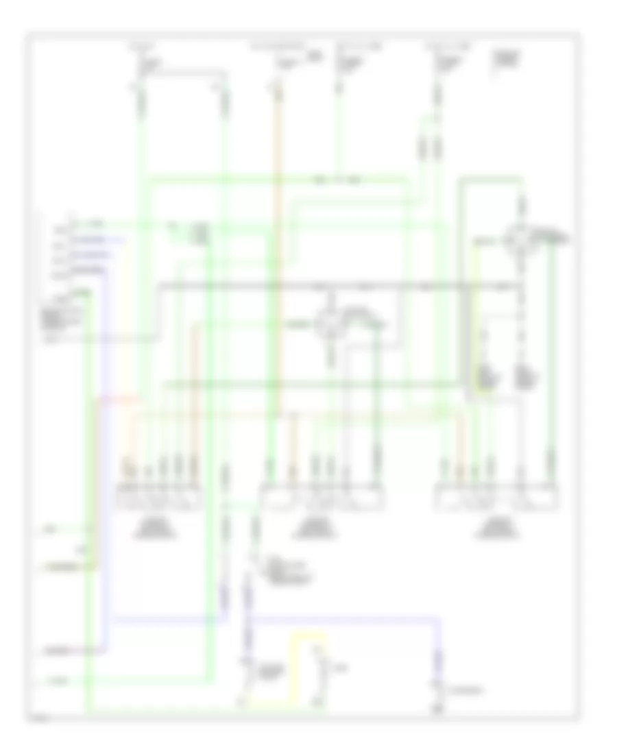
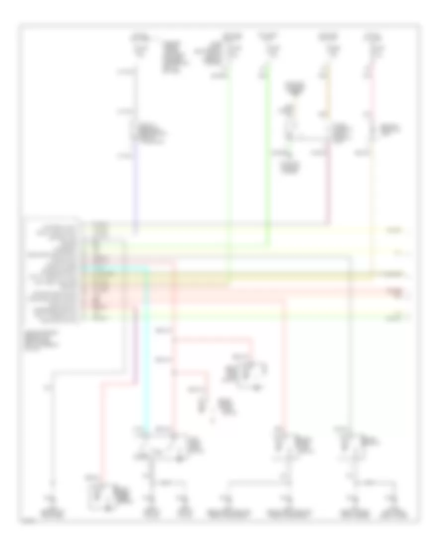
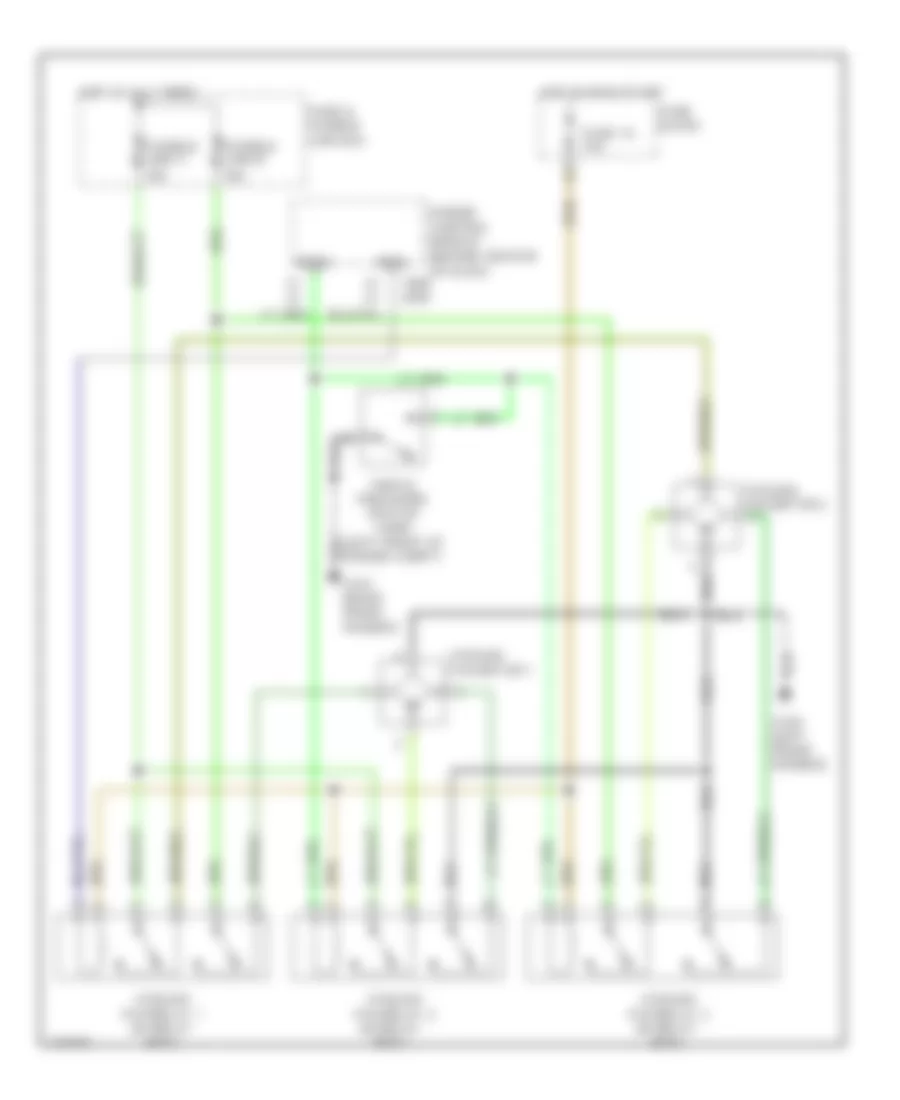
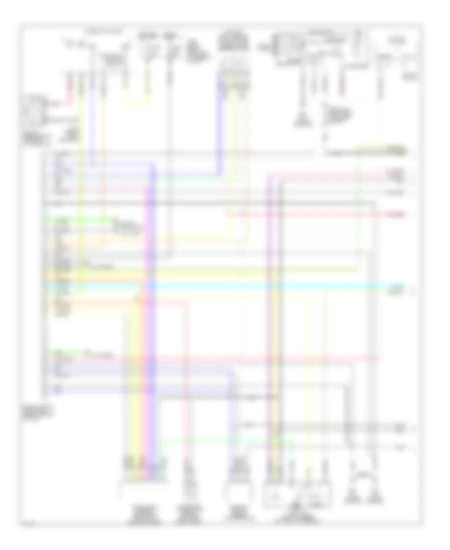
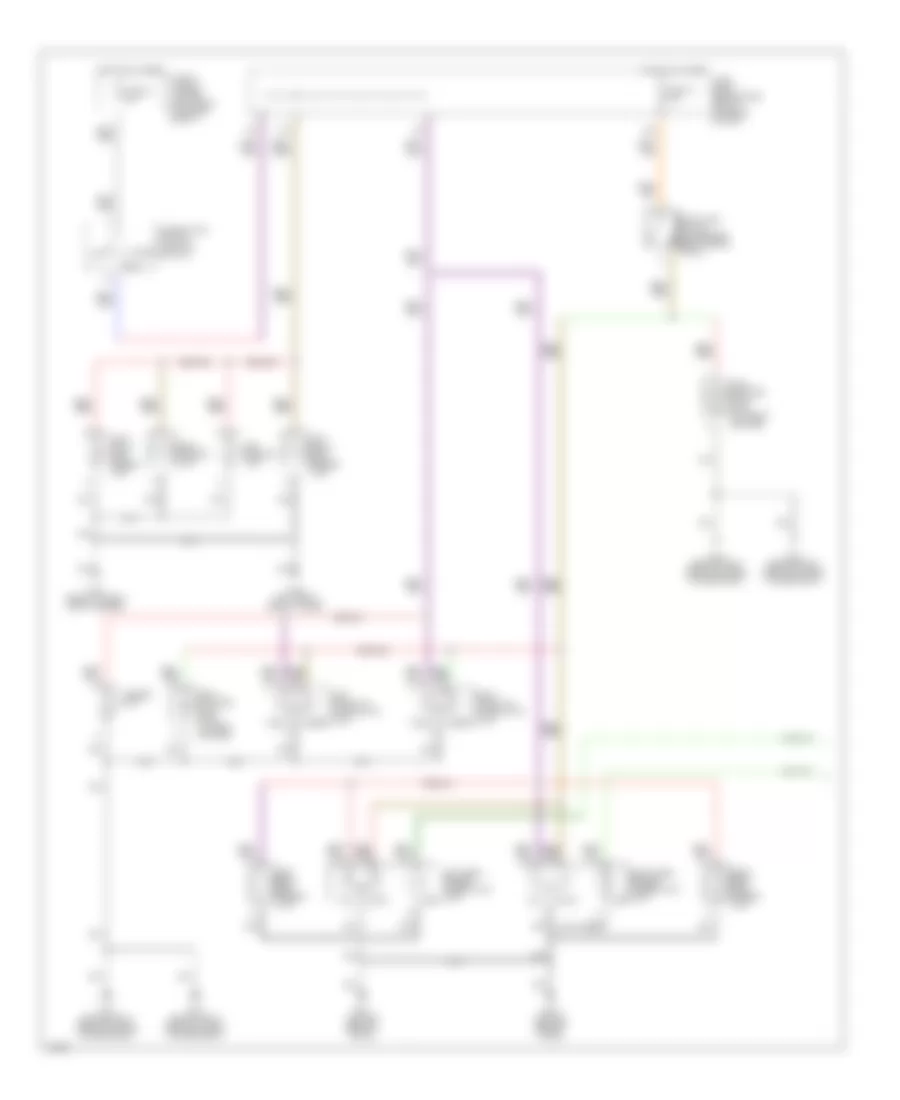
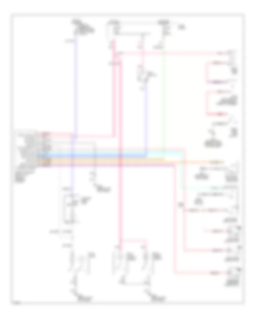
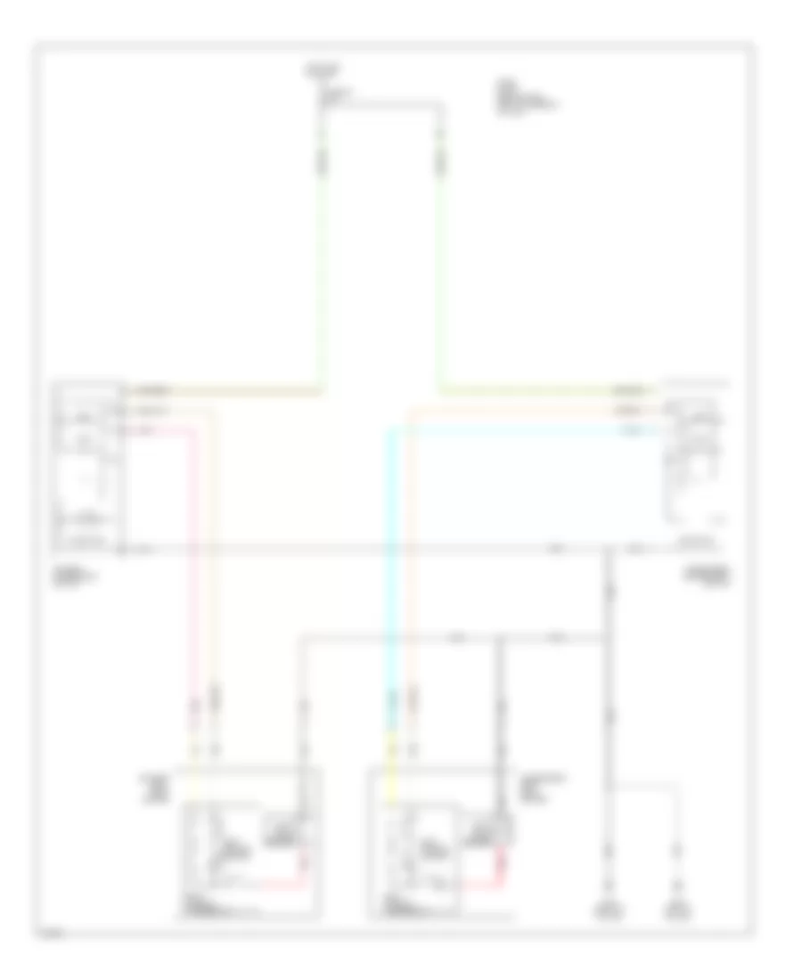
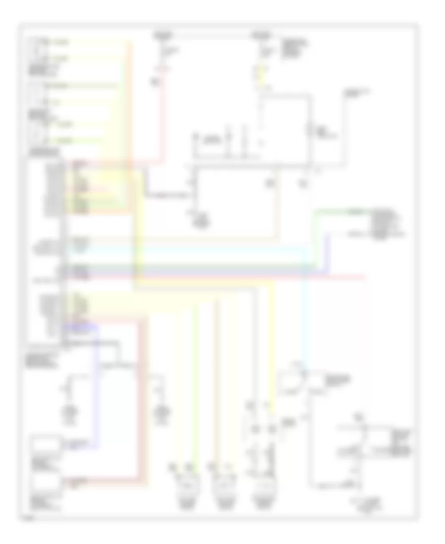
Automatic A/C Wiring Diagram (1 of 2) for Infiniti G20 t 1999
 https://portal-diagnostov.com/license.html
Automotive Electricians Portal FZCO
Automotive Electricians Portal FZCO
https://portal-diagnostov.com/license.html
https://portal-diagnostov.com/license.html
Automotive Electricians Portal FZCO
Automotive Electricians Portal FZCO
List of elements for Automatic A/C Wiring Diagram (1 of 2) for Infiniti G20 t 1999:
- "c1" fin
- (center front
- (center of
- (left front of engine compt)
- (left side
- (right de-
- (right side
- (right side kick panel)
- A/c auto amp
- Air mix door motor (center of dash)
- Amb sens
- Bat
- Blower motor (right side of dash)
- Comp on
- Dash) in vehicle sensor
- Fan cate
- Fan control amp (right side of dash)
- Fan f/b
- Fascia) ambient sensor
- Ficd
- Froster grille)
- Fuse 10a
- Fuse 15a
- Fuse 7.5a
- Fuse block
- G202
- G203
- Grd
- High
- Hot at all times
- Hot in on
- Ign
- Ign 2
- Ill
- Incar sens
- Intake actr +
- Intake actr -
- Intake code 1
- Intake code 2
- Intake door motor (right side of dash)
- Intake sens
- Intake sensor
- Interior lights system
- Lan-sig
- Light
- Low
- Mode door motor (center of dash)
- Of dash)
- Or start
- Pnk
- Position switch
- Sense grd
- Sun sens
- Sunload sensor
- Thermal transmitter (left front of engine)
- Thermo control amp
- Triple pressure switch
- Vactr
- W/t sens
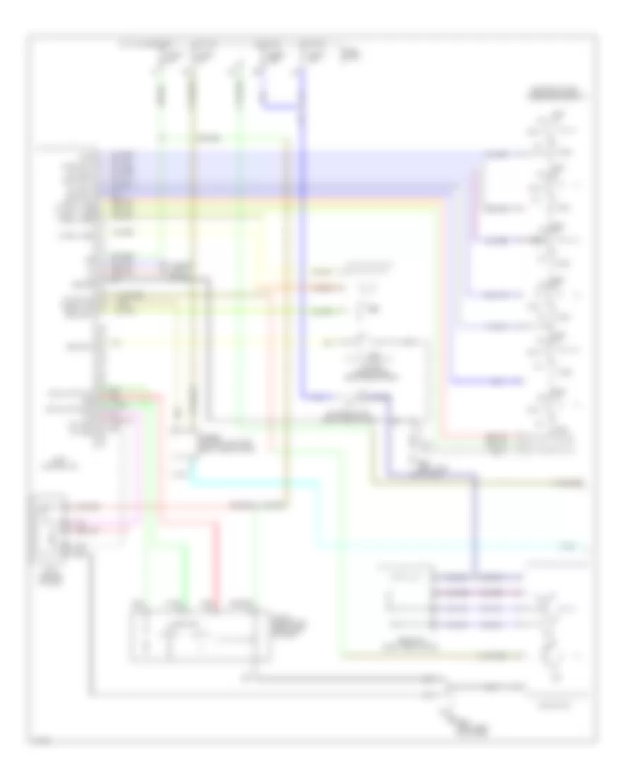
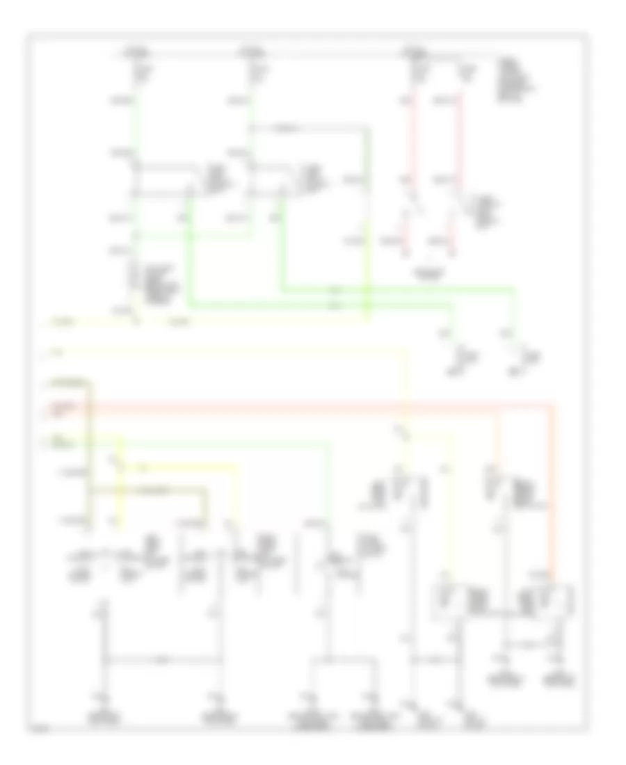
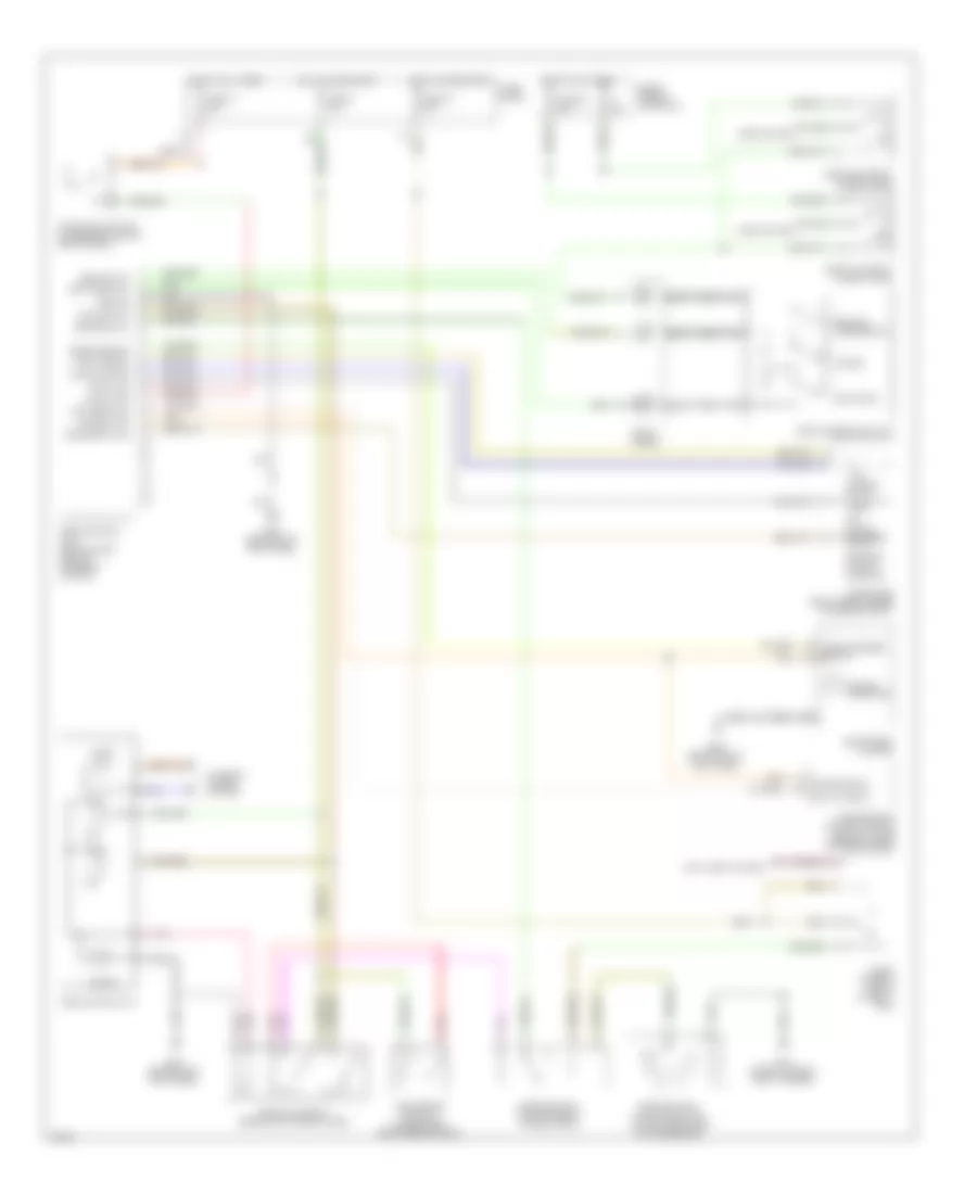
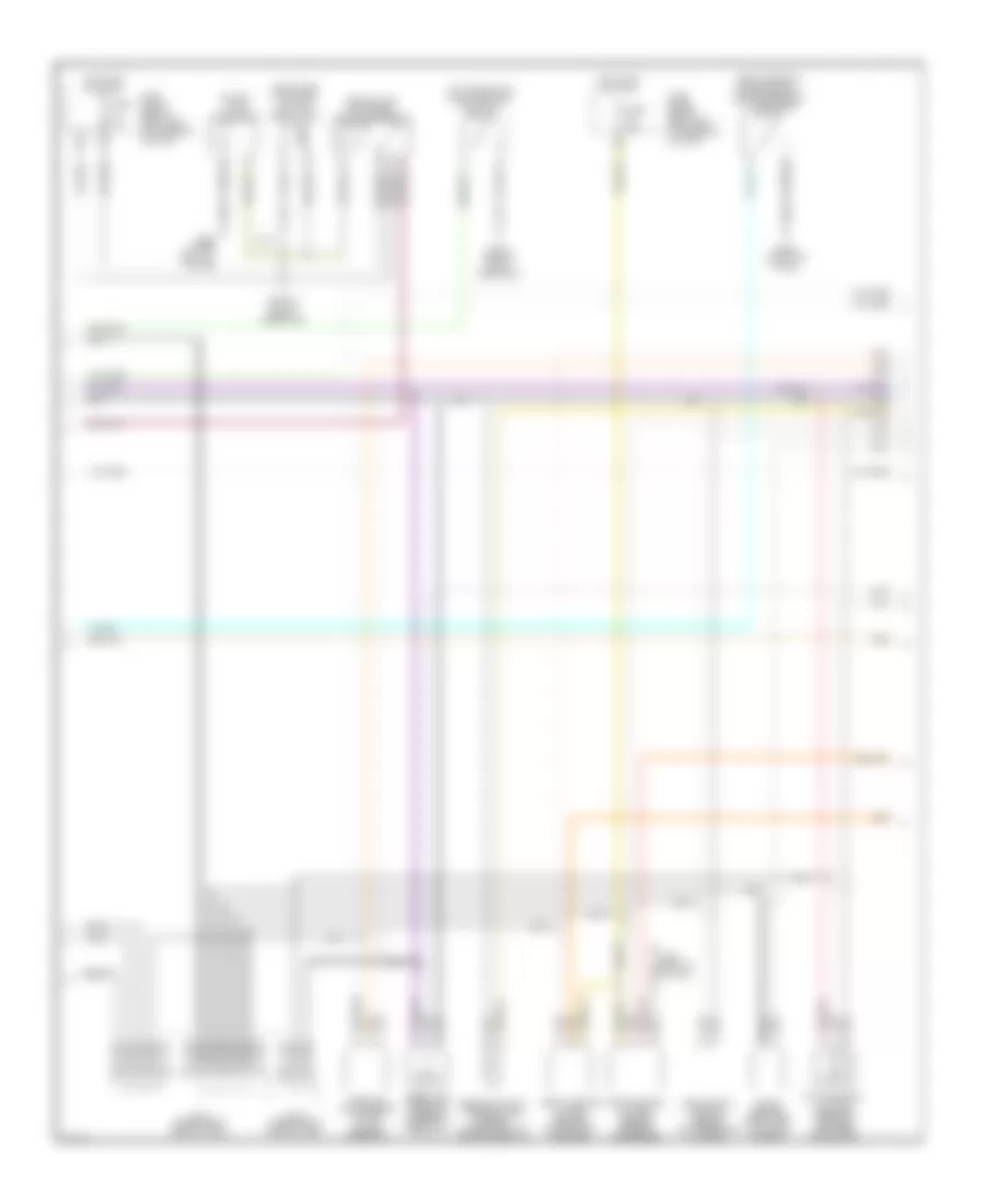
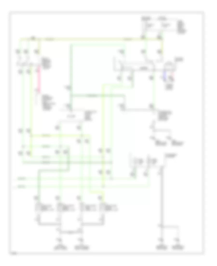
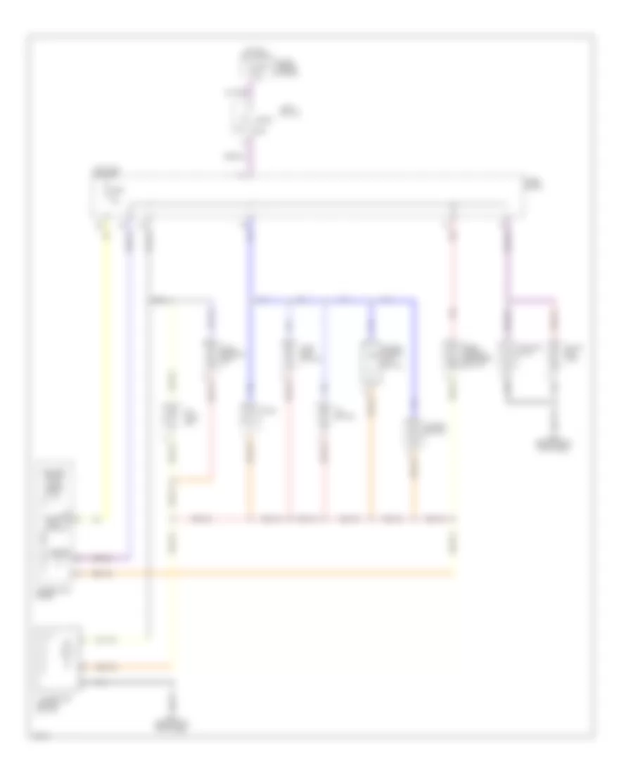
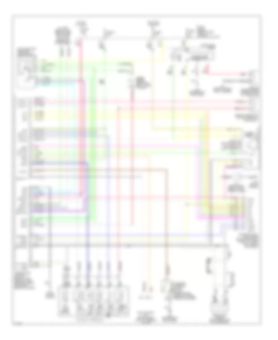
Automatic A/C Wiring Diagram (2 of 2) for Infiniti G20 t 1999
List of elements for Automatic A/C Wiring Diagram (2 of 2) for Infiniti G20 t 1999:
- 16h
- Acrly
- Air conditioner relay (right front of engine compt)
- Arcon
- Compressor
- Cooling fan motor 1
- Cooling fan motor 2
- Cooling fan relay 1 (left front of engine compt)
- Cooling fan relay 2 (left front of engine compt)
- Cooling fan relay 3 (left front of engine compt)
- Diode
- Engine control module (under center console)
- Fuse 16 10a
- Fuse 6 10a
- Fuse and fusible link box
- Fuse block
- Fusible link b 40a
- Fusible link c 40a
- G100 (left front of engine compt)
- G101 (right front of engine compt)
- Hot at all times
- Hot in on
- Hot in on and start
- Iacv-ficd solenoid valve
- Rfrh
- Rfrl
- Tasw
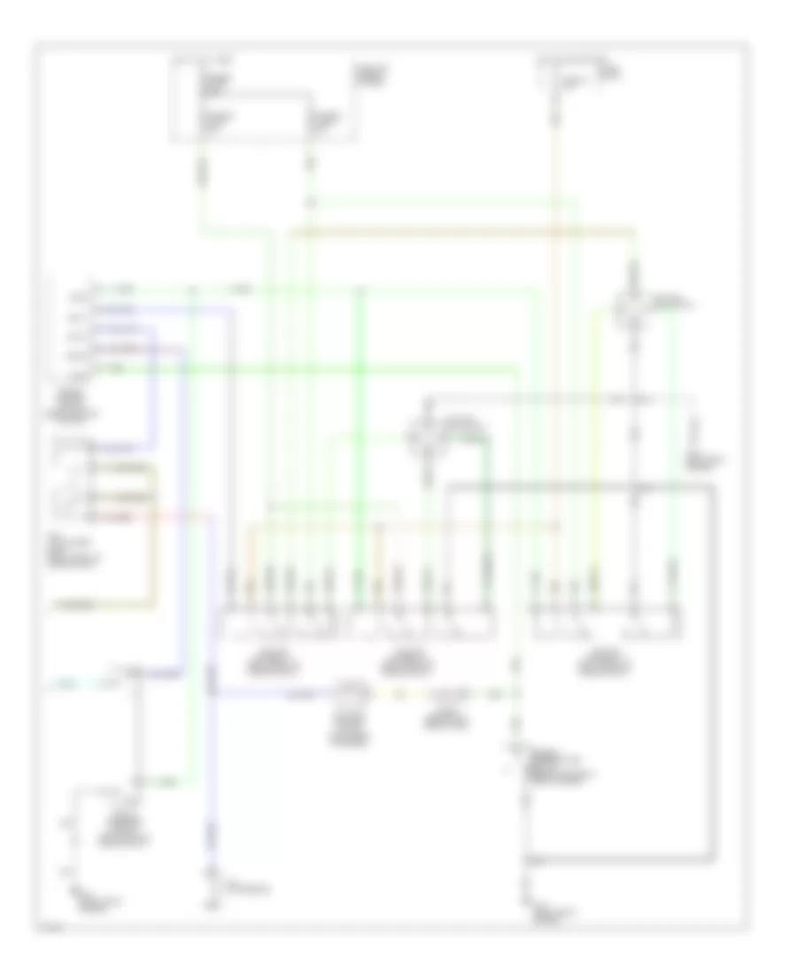
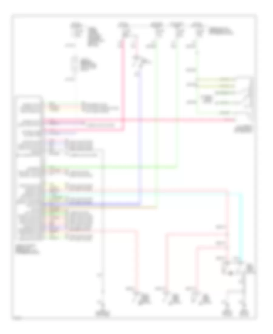
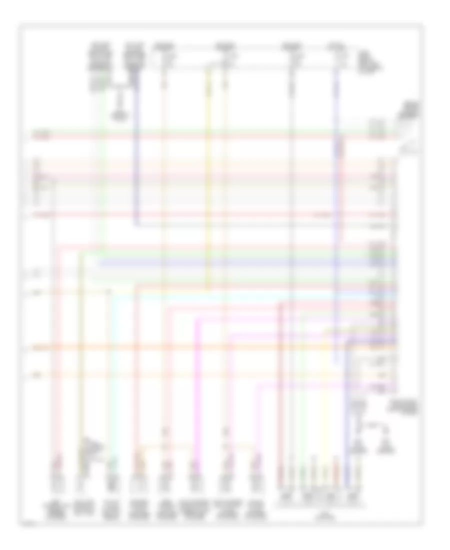
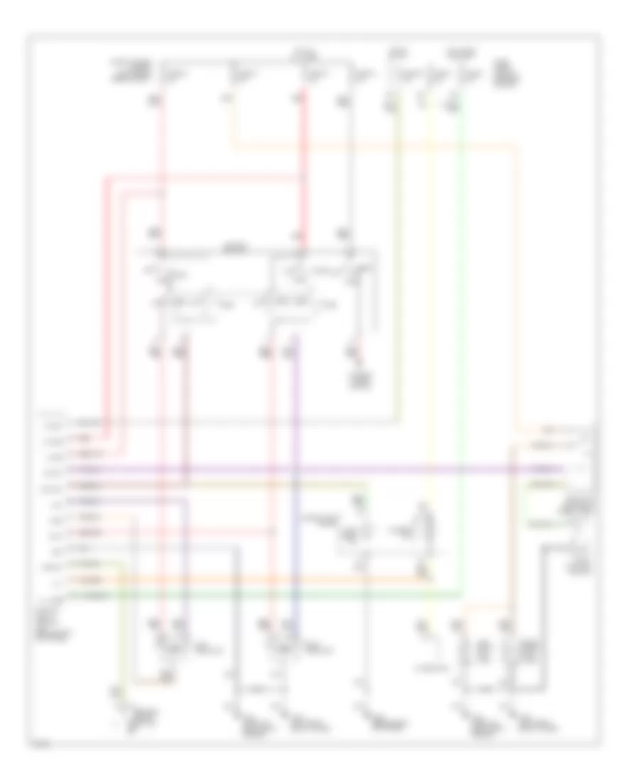
Manual A/C Wiring Diagram (1 of 2) for Infiniti G20 t 1999
List of elements for Manual A/C Wiring Diagram (1 of 2) for Infiniti G20 t 1999:
- (+) face, (-) def
- (+) fre, (-) rec
- (-) fre, (+) rec
- (-) vent, (+) def
- (center
- (center of dash)
- (right side of dash)
- 16h
- 3m 3c
- A/c switch
- Air mix door motor (right side of dash)
- Air mix mtr (cold)
- Air mix mtr (hot)
- B/l
- B/l input
- Blower motor
- Def
- Def input
- F/d
- F/d input
- Face
- Face input
- Fan switch
- Foot
- Foot input
- Fre
- Fre input
- Fuse 1 fuse 1 15a 15a
- Fuse 2 15a
- Fuse 6 10a
- Fuse 8 10a
- Fuse block
- G203 (right side
- G203 (right side kick panel)
- Ground
- Hot in on
- Hot in on, or start
- Ign
- Ill
- Intake door motor (right side of dash)
- Interior lights system
- Kick panel)
- Mode door motor
- Of dash)
- Off
- Pbr
- Ptc
- Ptc led+
- Ptc led-
- Push control unit
- Rec
- Rec input
- Red
- Resistor
- Thermo amp
- Thermo control amplifier
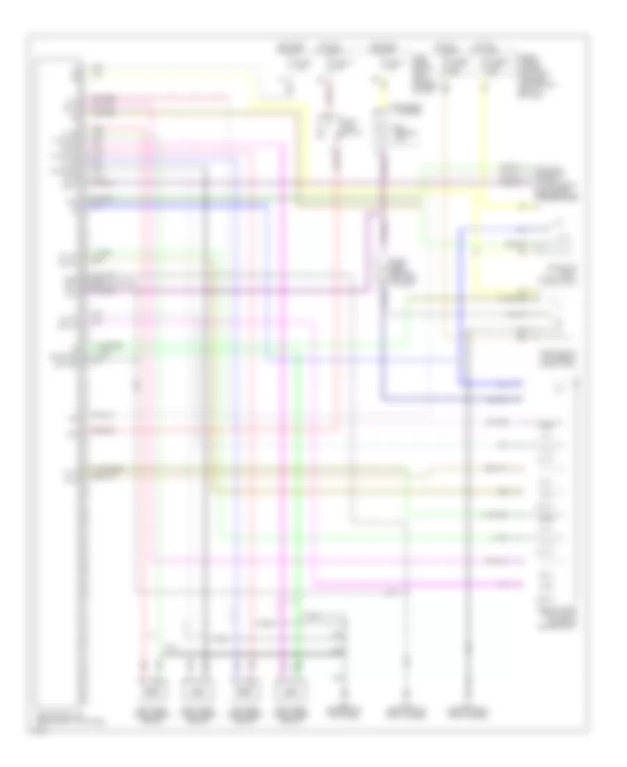
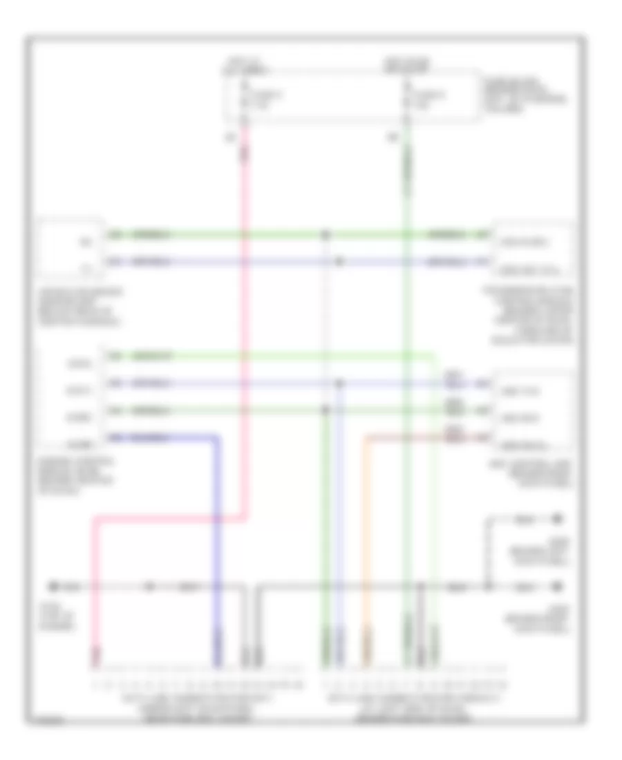
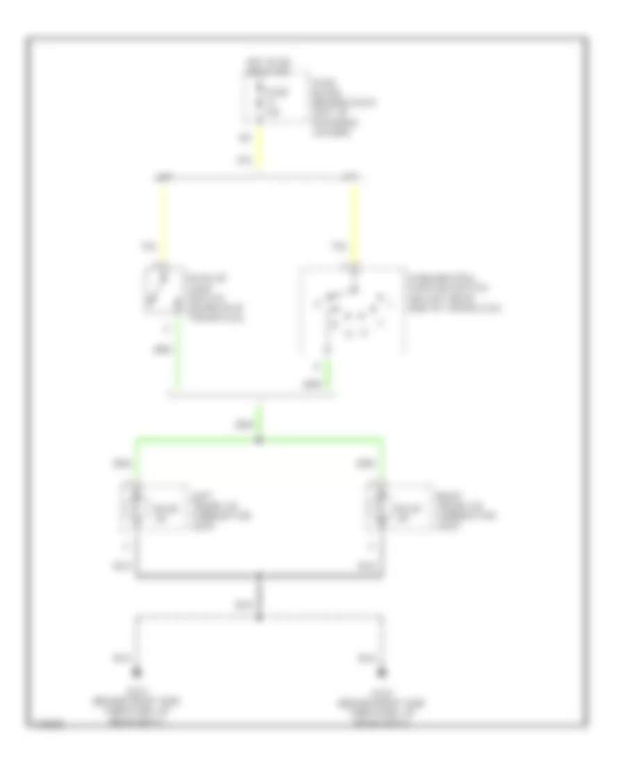
Manual A/C Wiring Diagram (2 of 2) for Infiniti G20 t 1999
List of elements for Manual A/C Wiring Diagram (2 of 2) for Infiniti G20 t 1999:
- A/c compressor
- Acrly
- Air conditioner relay (right front of engine compt)
- Ambient temperature switch (behind center of front bumper)
- Arcon
- Cooling fan motor 1
- Cooling fan motor 2
- Cooling fan relay 1 (right front of engine compt)
- Cooling fan relay 2 (right front of engine compt)
- Cooling fan relay 3 (right front of engine compt)
- Diode (behind left side of dash)
- Engine control module (behind center of dash)
- Fuse 16 10a
- Fuse and fusible link box
- Fuse block
- Fusible link b 40a
- Fusible link c 40a
- Fusible link e 100a
- G100 (left front fender)
- G101 (right front fender)
- Hot at all times
- Hot in on and start
- Iacv-ficd solenoid valve (right rear of engine)
- Rfrh
- Rfrl
- Tasw
- Triple pressure switch (left front of engine compt)
ANTI-LOCK BRAKES
Anti-lock Brake Wiring Diagrams for Infiniti G20 t 1999
List of elements for Anti-lock Brake Wiring Diagrams for Infiniti G20 t 1999:
- (consult) (at left side of dash, behind fuse box cover)
- Abs actuator (right front corner of engine compt)
- Abs control unit (behind right kick panel)
- Abs motor relay (in relay box)
- Abs solenoid valve relay (in relay box)
- Abs warning lamp
- Bls
- Data link connector
- Diag l
- Diode (abs) (behind left side of dash)
- Ecu gnd
- Fl in
- Fl out
- Fl ss
- Fl ss gnd
- Fr in
- Fr out
- Fr ss
- Fr ss gnd
- Fuse & fusible link box (left front of engine compartment, next to battery)
- Fuse 11 10a
- Fuse 14 15a
- Fuse 3 7.5a
- Fuse block (behind dash, left of steering column)
- Fusible link f 40a
- Fusible link h 40a
- G100 (front of left front fender)
- G101 (front of right front fender)
- G203 (behind right kick panel)
- Gnd1
- Gnd2
- Hot at all times
- Hot in on or start
- Instrument cluster
- Left front wheel speed sensor
- Left rear wheel speed sensor
- Nca
- Pnk
- Red
- Right front wheel speed sensor
- Right rear wheel speed sensor
- Rl in
- Rl out
- Rl ss
- Rl ss gnd
- Rr in
- Rr out
- Rr ss
- Rr ss gnd
- Rxd
- Sila
- Stop lamp switch
- Txd
ANTI-THEFT
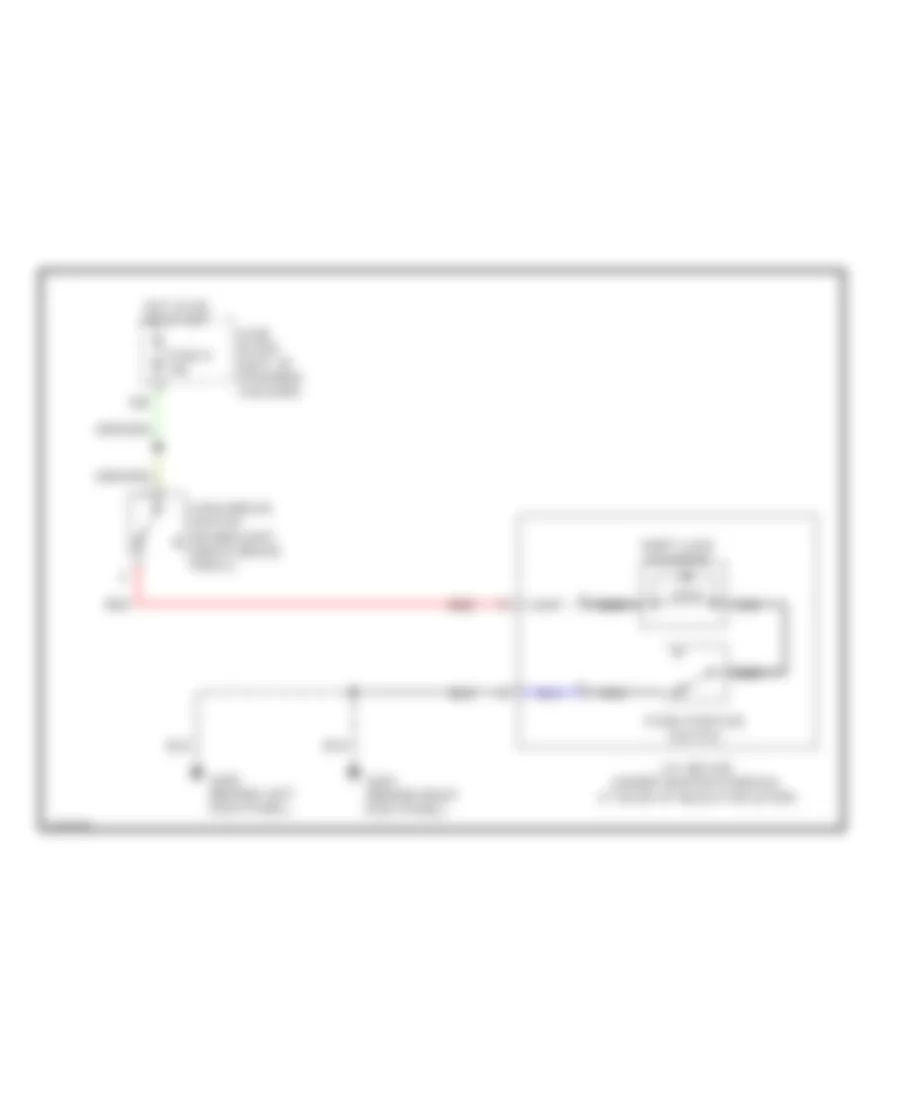
Anti-theft Wiring Diagram (1 of 2) for Infiniti G20 t 1999
List of elements for Anti-theft Wiring Diagram (1 of 2) for Infiniti G20 t 1999:
- Accessory
- Anti-theft indicator
- Battery (c/b)
- Circuit breaker 1 (behind dash, left of fuse block)
- Closed
- Door switches
- Dr door condition sw
- Driver's door sw
- Fuse 10a
- Fuse 7.5a
- Fuse and fusible link box (left front of engine compartment, next to battery)
- Fuse block (behind dash, left of steering column)
- Fuse d 30a
- G101 (front of right front fender)
- G102 (left front shock tower)
- G200 (behind left kick panel)
- G305 (right "b" pillar)
- G308 (left "b" pillar)
- G310 (behind right side trim panel of rear seat)
- Ground
- Hood switch
- Hot at all times
- Hot in acc or on
- Hot in on or start
- Ignition
- Key cylinder sw lck
- Key cylinder sw unlck
- Left front door switch
- Left rear door switch
- Open
- Panic alarm output
- Pass door condition sw
- Passenger's door sw
- Pnk
- Rear door condition sw
- Red
- Right front front door door switch switch
- Right rear door switch
- Security indicator lamp
- Smart entrance control unit (behind dash, left of steering column)
- Starter cutout
- Starting/ charging system
- Theft warning relay (in relay box)
- Trunk key switch
- Trunk room light switch
- Trunk switch
Anti-theft Wiring Diagram (2 of 2) for Infiniti G20 t 1999
List of elements for Anti-theft Wiring Diagram (2 of 2) for Infiniti G20 t 1999:
- (left front of engine compartment, next to battery)
- Anti-theft system diode (behind left side of dash, taped to harness)
- Full stroke
- Full stroke lock
- Full stroke unlock
- Fuse & fusible link box
- Fuse 10a
- Fuse 15a
- G200 (behind left kick panel)
- G203 (behind right kick panel)
- G305 (right "b" pillar)
- G308 (left "b" pillar)
- G310 (behind right side trim panel of rear seat)
- Headlights system
- Horn high
- Horn high relay (in relay box)
- Horn low
- Horn low relay (in relay box)
- Hot at all times
- Left front door key cylinder switch
- Left front door lock actuator
- Left rear door lock actuator
- Locked
- Mid stroke
- Red
- Right front door key cylinder switch
- Right front door lock actuator
- Right rear door lock actuator
- Theft warning lamp relay (in relay box)
- Trunk lid key cylinder switch
- Unlocked
BODY COMPUTER
Body Computer Wiring Diagrams for Infiniti G20 t 1999
List of elements for Body Computer Wiring Diagrams for Infiniti G20 t 1999:
- 11b
- Accessory
- Anti-theft system
- Batt saver output
- Battery (c/b)
- Battery (fuse)
- Central lock sw
- Central unlck sw
- Circuit breaker 1 (behind dash, left of fuse block)
- Condition switch
- Defogger system
- Door lock output
- Door locks system
- Door switch
- Door unlk output
- Dr door switch
- Dr door unlck
- Exterior lights system
- Fuse & fusible link box (left front of engine compartment, next to battery)
- Fuse 10a
- Fuse 7.5a
- Fuse block (j/b) (behind dash, left of steering column)
- Fuse d 30a
- G200 (behind left kick panel)
- G305 (right "b" pillar)
- G308 (left "b" pillar)
- Ground
- Hazard output
- Hood switch
- Hot at all times
- Hot in accy or on
- Hot in on or start
- Ignition
- Interior lights system
- Key cyl sw lock
- Key cyl sw unlck
- Key switch
- Left front door switch
- Left rear door switch
- Light switch
- Multi-remote control relay (on fuse block)
- Panic alarm out
- Pass door switch
- Pnk
- Red
- Right front door switch
- Right rear door switch
- Room lamp output
- Rr def output
- Rr defggr switch
- Seat belt switch
- Security indicator
- Smart entrance control unit (behind dash, left of steering column)
- Starter cutout
- Starting/charging system
- Trunk key switch
- Trunk switch
- Warning system
COMPUTER DATA LINES
Computer Data Lines for Infiniti G20 t 1999
List of elements for Computer Data Lines for Infiniti G20 t 1999:
- Abs control unit (behind right kick panel)
- Abs diag l
- Abs rxd
- Abs txd
- Air bag diagnosis sensor unit (below rear of center console)
- Data link connector (for consult) (at left side of dash, behind fuse box cover)
- Data link connector (for gst) (under left dash panel, near fuse box cover)
- Engine control module (ecm) (behind center of dash)
- Fuse 5 7.5a
- Fuse 8 10a
- Fuse block (behind dash, left of steering column)
- G134 (top of engine)
- G200 (behind left kick panel)
- G203 (behind right kick panel)
- Hot at all times
- Hot in on or start
- Kline
- Pnk
- Scicl
- Scirx
- Scitx
- Sss in (rx)
- Sss out (tx)
- Transmission (tcm) control module (behind lower center of dash, forward of selector lever)
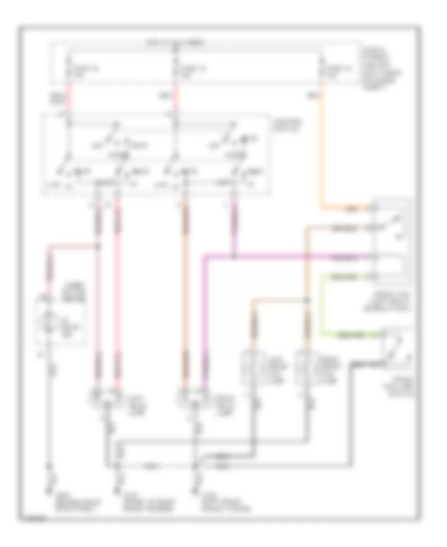
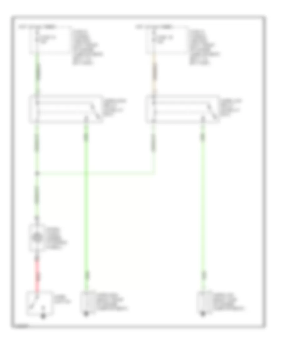
COOLING FAN
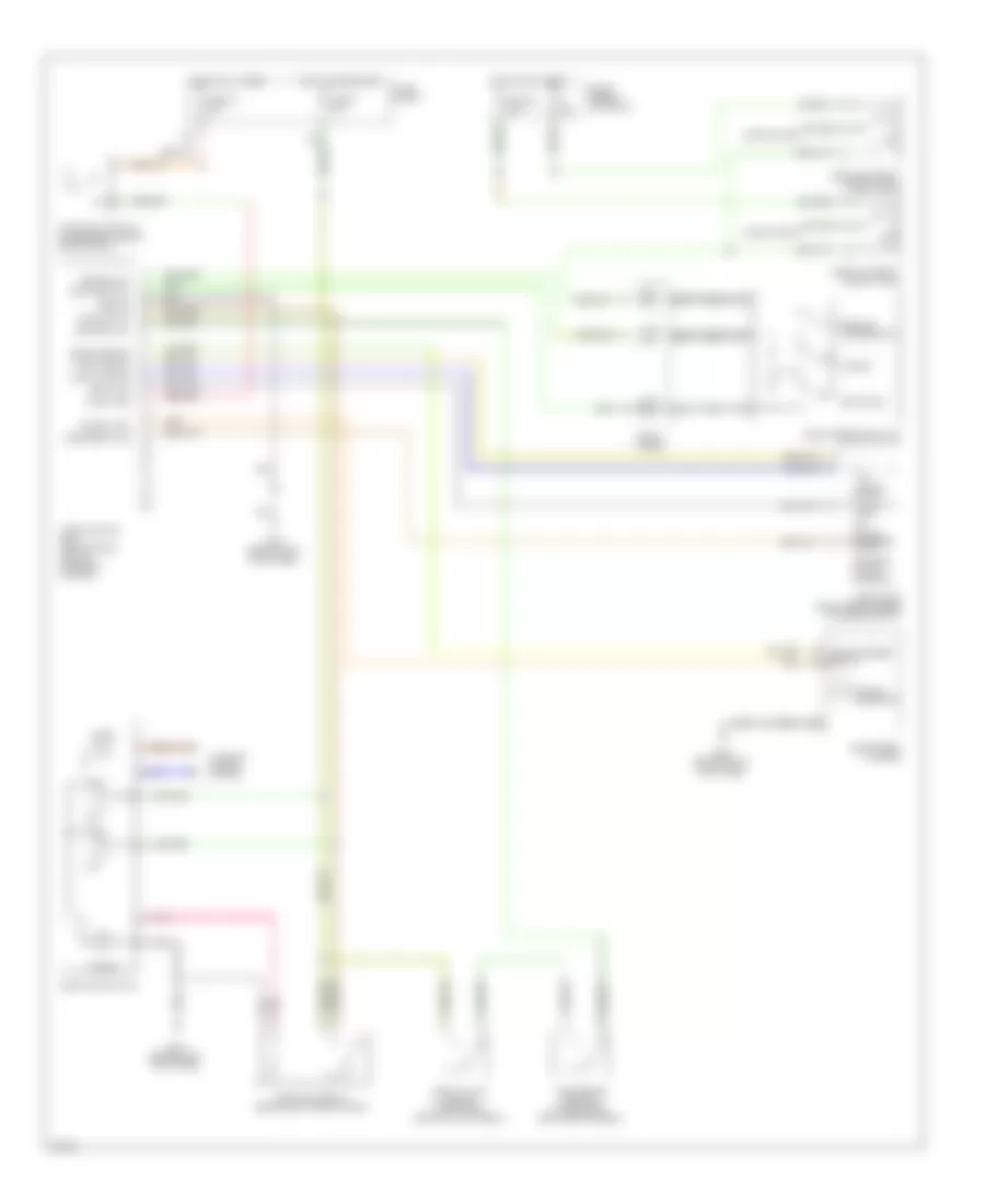
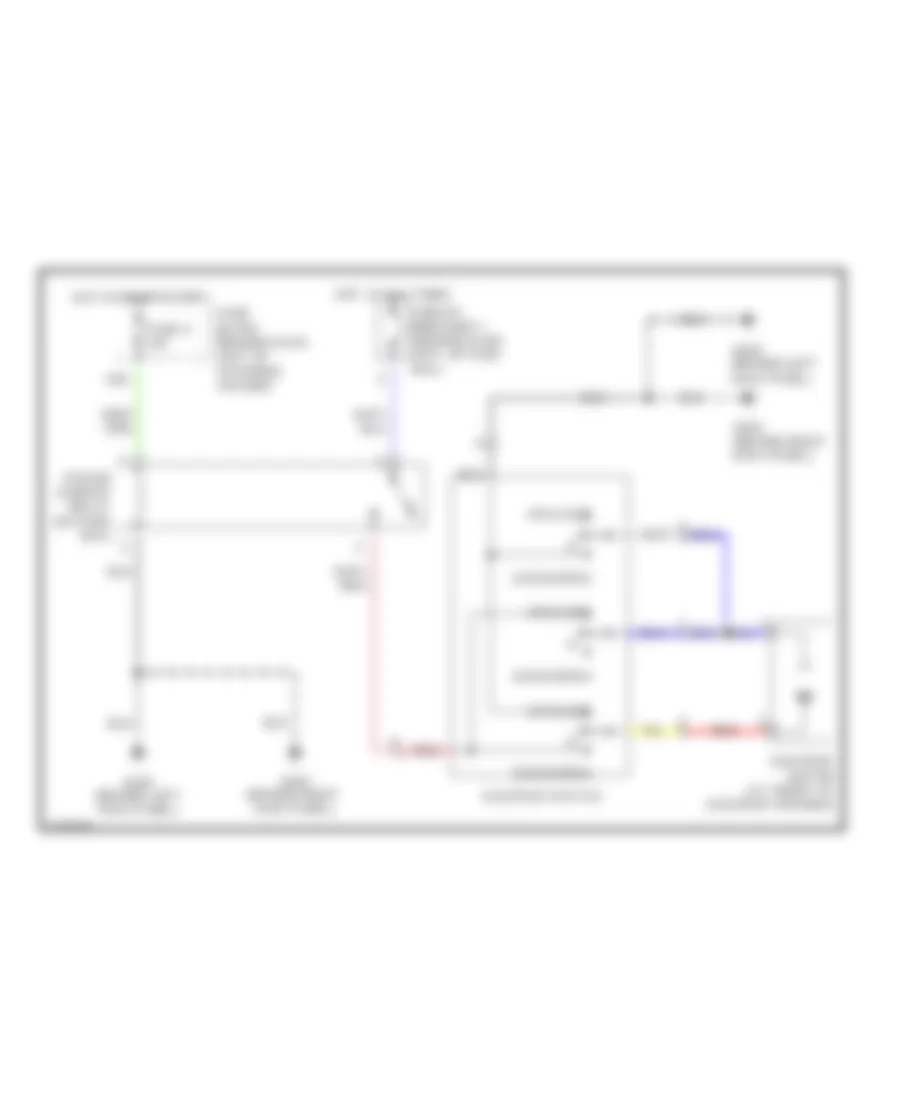
Cooling Fan Wiring Diagram for Infiniti G20 t 1999
List of elements for Cooling Fan Wiring Diagram for Infiniti G20 t 1999:
- Cooling fan motor 1
- Cooling fan motor 2
- Cooling fan relay 1 (in relay box)
- Cooling fan relay 2 (in relay box)
- Cooling fan relay 3 (in relay box)
- Engine control module (behind center of dash)
- Fuse & fusible link box
- Fuse 16 10a
- Fuse block
- Fusible link b 40a
- Fusible link c 40a
- G100 (left front fender)
- G101 (right front fender)
- Hot at all times
- Hot in on & start
- Rfrh
- Rfrl
- Triple pressure switch (1999) (left front of engine compt)
CRUISE CONTROL
Cruise Control Wiring Diagram, with A/T for Infiniti G20 t 1999
List of elements for Cruise Control Wiring Diagram, with A/T for Infiniti G20 t 1999:
- 10a
- 15d
- Air valve
- Air valve solenoid
- Anti-theft system
- Ascd brake switch (on bracket, above brake pedal)
- Ascd control unit (behind dash, left of steering column)
- Ascd hold relay (behind left side of dash)
- Ascd main switch
- Ascd pump (right rear corner of engine compt)
- Ascd steering switch
- Brake nc sw
- Cancel
- Cruise indicator
- Cruise lamp
- Cruise signal
- Fuse & fusible link block
- Fuse 14 15a
- Fuse 16 10a
- Fuse 36 10a
- Fuse 8 10a
- Fuse block
- G101 (front of right front fender)
- G200 (behind left kick panel)
- G203 (behind right kick panel
- Ground
- Horn high relay (in relay box)
- Horn low relay (in relay box)
- Horn system
- Hot at all times
- Hot in on or start
- Illum.
- Instrument cluster
- Interior lights system
- Main switch
- Nca
- Od cancel sig
- Od cut signal
- Off
- On ind.
- Park/neutral position relay (in relay box)
- Park/neutral position switch (on left rear side of transaxle)
- Pnk
- Pump common
- Red
- Release valve
- Release valve solenoid
- Res/acc sw
- Resume/ accelerate
- Set/coast
- Set/coast sw
- Speed sensor
- Spiral cable
- Stop lamp
- Stoplight switch (on bracket above brake pedal)
- Theft warning relay (in relay box)
- Transmission control module (behind lower center of dash)
- Vacuum motor
- Vehicle speed output
Cruise Control Wiring Diagram, with M/T for Infiniti G20 t 1999
List of elements for Cruise Control Wiring Diagram, with M/T for Infiniti G20 t 1999:
- 10a
- 15d
- Air valve
- Air valve solenoid
- Ascd brake switch (on bracket, above brake pedal)
- Ascd clutch switch (on bracket, above clutch pedal)
- Ascd control unit (behind dash, left of steering column)
- Ascd hold relay (behind left side of dash)
- Ascd main switch
- Ascd pump (right rear corner of engine compt)
- Ascd steering switch
- Brake nc sw
- Cancel
- Cruise indicator
- Cruise lamp
- Fuse & fusible link block
- Fuse 14 15a
- Fuse 36 10a
- Fuse 8 10a
- Fuse block
- G200 (behind left kick panel)
- G203 (behind right kick panel
- Ground
- Horn high relay (in relay box)
- Horn low relay (in relay box)
- Horn system
- Hot at all times
- Hot in on or start
- Illum.
- Instrument cluster
- Interior lights system
- Main switch
- Nca
- Off
- On ind.
- Pnk
- Pump common
- Release valve
- Release valve solenoid
- Res/acc sw
- Resume/ accelerate
- Set/coast
- Set/coast sw
- Speed sensor
- Spiral cable
- Stop lamp
- Stoplight switch (on bracket above brake pedal)
- Vacuum motor
- Vehicle speed output
DEFOGGERS
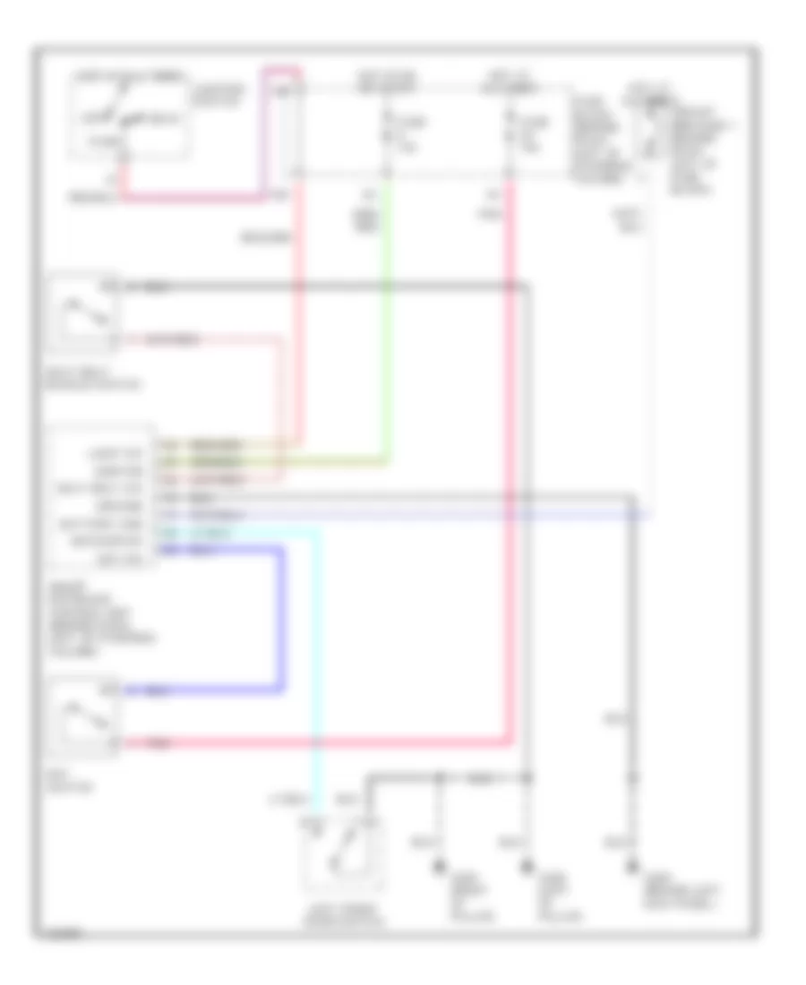
Defogger Wiring Diagram for Infiniti G20 t 1999
List of elements for Defogger Wiring Diagram for Infiniti G20 t 1999:
- (behind dash, left of steering column) smart entrance control unit
- Condenser
- Def out
- Def sw
- Door mirror defogger relay (behind left kick panel)
- Fuse & fusible link box (left front of engine compt, next to battery)
- Fuse 10a
- Fuse 10a
- Fuse 20a
- Fuse block (behind dash, left of steering column)
- G200 (behind left kick panel)
- G203 (behind right kick panel)
- G313 (right side of rear shelf)
- Hot at all times
- Hot in acc or on
- Hot in on or start
- Ignition
- Illum
- Interior lights system
- Left door mirror defogger
- Nca
- On ind
- Rear window defogger
- Rear window defogger relay (behind left kick panel)
- Rear window defogger switch
- Red
- Right door mirror defogger
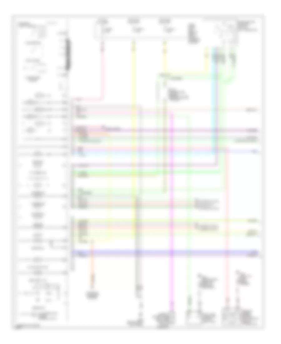
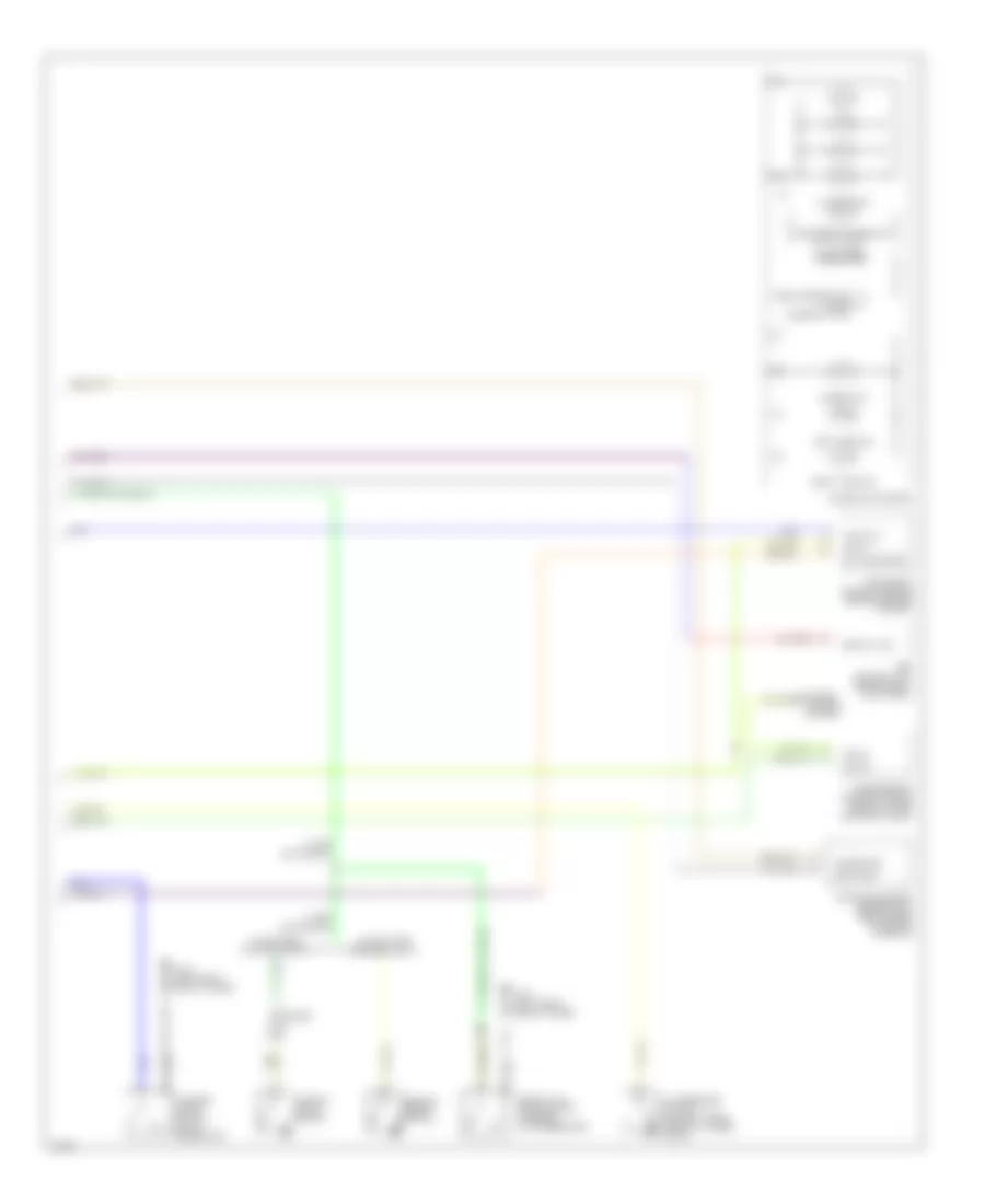
ENGINE PERFORMANCE
2.0L
2.0L, Engine Performance Wiring Diagrams (1 of 3) for Infiniti G20 t 1999
List of elements for 2.0L, Engine Performance Wiring Diagrams (1 of 3) for Infiniti G20 t 1999:
- (top right side of engine) evap canister purge volume control valve
- A/c system
- Camshaft position sensor (in distributor)
- Closed
- Combination meter
- Condenser
- Cooling fans system
- Distributor
- Engine control module (ecm) (behind center of dash)
- Fuse 10a
- Fuse block (behind dash, left of steering column)
- G107 (behind right headlamp)
- G131 (on intake manifold)
- Hot at all times
- Hot in on or start
- Hot in start
- Ignition coil
- Ignition switch
- Intake air temperature sensor (left front of eng compt)
- Lock
- Malfunction indicator
- Nca
- Power transistor
- Pwr
- Red
- Resistor (left front of engine compt)
- Spark plugs
- Start
- Tach
- Throttle position sensor (on throttle assembly)
- Transmission control module (tcm) (forward of selector lever)
- Vehicle speed sensor (top right of transaxle)
- Vss in
- Vss out
- Wide open
2.0L, Engine Performance Wiring Diagrams (2 of 3) for Infiniti G20 t 1999
List of elements for 2.0L, Engine Performance Wiring Diagrams (2 of 3) for Infiniti G20 t 1999:
- (behind
- (behind left kick panel) fuel pump relay
- (in fuel tank) fuel pump
- (on transaxle) park/ neutral position switch
- (right rear of engine compt) power steering oil pressure switch
- (right side of engine) iacv-air regulator
- 10d
- 15b
- Absolute pressure sensor (center of firewall)
- Crankshaft position sensor (on transaxle housing)
- Engine coolant temperature sensor (lower front of intake manifold)
- Evap control system pressure sensor (left rear of vehicle)
- Front heated oxygen sensor (on exhaust manifold)
- Fuse 10a
- Fuse 15a
- Fuse block (behind dash, left of steering column)
- G107
- G107 (behind
- G200 (left kick panel)
- G308 (left "b" pillar)
- G905 (lower
- Hot in on or start
- J/c 1 (under right side of dash)
- J/c 2 (under right side of dash)
- Knock sensor (right side of engine block)
- Mass air- flow sensor (on air intake assembly)
- Nca
- Rear heated oxygen sensor (rear of converter)
- Right "c" pillar)
- Right headlamp)
2.0L, Engine Performance Wiring Diagrams (3 of 3) for Infiniti G20 t 1999
List of elements for 2.0L, Engine Performance Wiring Diagrams (3 of 3) for Infiniti G20 t 1999:
- (behind center of dash) ecm relay
- (left side of dash, behind fuse box cover)
- (left side of dash, near fuse box cover) data link connector (for gst)
- 13d
- Data link connector (for consult)
- Eccs control module (ecm) (behind center of dash)
- Egr temperature sensor (top rear of engine)
- Egrc solenoid valve (right side of engine)
- Evap canister purge control solenoid valve (right side of engine)
- Evap canister vent control valve (left rear of vehicle)
- Fuel injectors
- Fuel tank gauge unit (on top of fuel tank)
- Fuse 10a
- Fuse 7.5a
- Fuse block (behind dash, left of steering column)
- G131 (on intake manifold)
- G200 (left kick panel)
- G905 (lower right "c" pillar)
- Hot at all times
- Hot in on or start
- Iacv-aac valve (top right front of engine)
- Map/baro solenoid valve (right side of engine)
- Pnk
- Vacuum by-pass valve (left rear of vehicle)
EXTERIOR LIGHTS
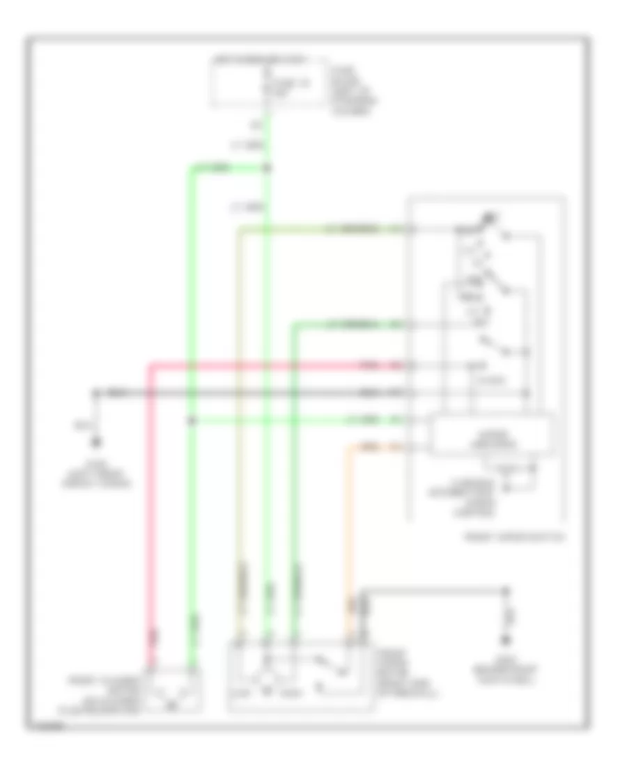
Backup Lamps Wiring Diagram for Infiniti G20 t 1999
List of elements for Backup Lamps Wiring Diagram for Infiniti G20 t 1999:
- A/t
- Back up
- Back-up light switch (on rear of transaxle)
- Fuse 10a
- Fuse block (behind dash, left of steering column)
- G310 (behind right side trim panel of rear seat)
- Hot in on or start
- Left trunk lid combination light
- M/t
- Park/neutral position switch (on left rear side of transaxle)
- Right trunk lid combination light
Exterior Lamps Wiring Diagram (1 of 2) for Infiniti G20 t 1999
List of elements for Exterior Lamps Wiring Diagram (1 of 2) for Infiniti G20 t 1999:
- 13h
- 14h
- 15d
- Combination switch (lighting switch)
- Fuse & fusible link box (left front of engine compt)
- Fuse 14 15a
- Fuse 34 10a
- Fuse block (behind dash, left of steering column)
- G101 (front of right front fender)
- G102 (left front shock tower)
- G310 (behind right side trim panel of rear seat)
- G407 (center rear of trunk)
- Head
- High- mounted stop light (w/ rear spoiler)
- High- mounted stop light (w/o rear spoiler)
- Hot at all times
- Left front side marker lamp
- Left parking lamp
- Left rear fender combination light
- Left rear side marker lamp
- Left trunk lid combination light
- License lamp
- Off
- Park
- Right front side marker lamp
- Right parking lamp
- Right rear fender combination light
- Right rear side marker lamp
- Right trunk lid combination light
- Stop
- Stop lamp switch (on bracket, above brake pedal)
- Tail
- Turn
Exterior Lamps Wiring Diagram (2 of 2) for Infiniti G20 t 1999
List of elements for Exterior Lamps Wiring Diagram (2 of 2) for Infiniti G20 t 1999:
- Combination flasher unit (behind left side of dash)
- Combination switch (turn signal switch)
- Fuse 12 7.5a
- Fuse 20 10a
- Fuse block (behind dash, left of steering column)
- G101 (front of right front fender)
- G102 (left front shock tower)
- G200 (behind left kick panel)
- G203 (behind right kick panel)
- Hazard
- Hazard switch
- Hot at all times
- Hot in on or start
- Ill
- Instrument cluster
- Interior lights system
- Left front turn signal lamp
- Left side turn signal lamp
- Left turn ind
- Multi- remote control relay (on fuse block)
- Pnk
- Right front turn signal lamp
- Right side turn signal lamp
- Right turn ind
- Smart entrance control unit (behind dash, left of steering column)
GROUND DISTRIBUTION
Ground Distribution Wiring Diagram for Infiniti G20 t 1999
List of elements for Ground Distribution Wiring Diagram for Infiniti G20 t 1999:
- A/c auto amp, brake fluid level switch, hood
- A/t device, rear window defogger switch, sunroof
- Abs control unit
- Air bag diagnosis sensor unit shield wire
- Ascd hold relay, ascd control unit, data link
- Camshaft position sensor shield wire, crankshaft
- Camshaft position sensor, evap control system
- Combination light, left rear side
- Connector for consult, data link connector for gst, clutch interlock switch, combination flasher
- Control unit, a/c auto amp, power steering oil pressure switch, mode door motor, air mix door
- Control unit, power window main switch, driver's
- Cooling fan relay 3, abs solenoid valve relay,
- Data link connector for gst, mass airflow
- Daytime light control unit, park/neutral position
- Diagnosis sensor unit, glove box light, cigarette lighter, intake door motor, fan control amp, air
- Distributor, engine control module
- Door key cylinder switch, driver's door lock actuator, ascd main switch, accessory relay,
- Door key cylinder switch, passenger's door mirror actuator, front wiper motor, ashtray
- Door lock actuator
- Driver's heated seat switch,
- Driver's power seat, driver's heated
- Fan relay 2, left side turn signal light, left
- Front side marker light, left front turn signal
- Front turn signal light, right front fog light,
- Fuel tank gauge unit, fuel pump,
- G100 (front of left front fender)
- G101 (front of right front fender)
- G102 (left front shock tower)
- G134 (top of engine)
- G200 (behind left kick panel)
- G203 (behind right kick panel)
- G305 (right "b" pillar)
- G308 (left "b" pillar)
- G310 (behind right side trim panel of rear seat)
- G313 (right side of rear shelf)
- G407 (center rear of trunk)
- Gauge, tachometer, odo/trip meter, speedometer,
- Heated oxygen sensor, driver's door
- High-mounted stop light, power antenna, trunk lid key cylinder
- Iacv-air regulator
- Ignition relay, blower relay
- Illumination, a/t device, fan switch, push
- Indicator, a/t indicators, high beam indicator,
- Left front wheel sensor shield wire, right front
- License light, trunk room light
- Light, right rear combination light
- Light, triple pressure switch, front fog lamp
- Map light, integrated homelink transmitter
- Marker light
- Mirror remote control switch, smart entrance
- Mix door motor, passenger's vanity mirror light,
- Motor, potentio temperature control (ptc), cruise
- Passenger's door lock actuator, passenger's
- Passenger's heated seat switch, left rear door lock actuator, right rear
- Position sensor shield wire, throttle position sensor shield wire, knock sensor shield wire, engine control module, engine control module
- Pressure sensor shield wire
- Rear window defogger
- Relay, driver's door mirror actuator, door
- Right front side marker light, ambient air temperature switch, vehicle speed sensor,
- Right rear side marker light, left rear combination light, right rear
- Seat, passenger's heated seat, rear
- Sensor
- Sensor shield wire, absolute pressure sensor shield wire, rear heated oxygen sensor shield wire, front heated oxygen sensor shield wire,
- Sensor, right rear wheel
- Shield wire, transmission control module,
- Switch, bose speaker amp,
- Switch, cooling fan motor 1, cooling fan motor 2, right headlight, left front fog lamp, cooling
- Switch, driver's seat buckle switch,
- Switch, driver's vanity mirror light, air bag
- Switch, front wiper switch, washer level switch
- Switch, left parking light, left headlight, right parking light, right side turn signal light, right
- Switch, left rear combination
- Turn signal indicator, air bag warning light, fuel
- Unit, illumination control switch, power window
- Water temperature gauge
- Wheel sensor shield
- Wire, left rear wheel
HEADLIGHTS
Headlight Wiring Diagram, with DRL for Infiniti G20 t 1999
List of elements for Headlight Wiring Diagram, with DRL for Infiniti G20 t 1999:
- Alt
- Alternator
- Charge ind
- Combination meter
- Daytime light control unit (behind right kick panel)
- Dim sw
- Front fog lamp switch
- Front fog light relay (in relay box)
- Fuse & fusible link box (left side of engine compt)
- Fuse 11 10a
- Fuse 26 10a
- Fuse 32 15a
- Fuse 33 15a
- Fuse 34 10a
- Fuse 43 15a
- Fuse 8 10a
- Fuse block (left of steering column)
- G101 (front of right front fender)
- G102 (left front shock tower)
- G203 (behind right kick panel)
- Gnd
- Head
- High beam ind
- Hot at all times
- Hot in run or start
- Hot in start
- Ign
- Interior lights system
- L fuse
- L grd
- L sw
- Left front fog lamp
- Left headlamp
- Lighting switch
- Low
- Main sw
- Off
- Park
- Parking brake switch
- Pass
- Pkb sw
- R fuse
- R sw
- Red
- Right front fog lamp
- Right headlamp
- Start
Headlight Wiring Diagram, without DRL for Infiniti G20 t 1999
List of elements for Headlight Wiring Diagram, without DRL for Infiniti G20 t 1999:
- (left front of engine compt)
- Combi- nation meter
- Front fog lamp switch
- Front fog- light relay (in relay box)
- Fuse & fusible
- Fuse 32 15a
- Fuse 33 15a
- Fuse 43 15a
- G101 (front of right front fender)
- G102 (left front shock tower)
- G203 (behind right kick panel)
- Head
- Hi beam ind
- Hot at all times
- Left front fog lamp
- Left head- lamp
- Lighting switch
- Link box
- Low
- Low hi
- Off
- Park
- Pass
- Red
- Right front fog lamp
- Right head- lamp
HORN
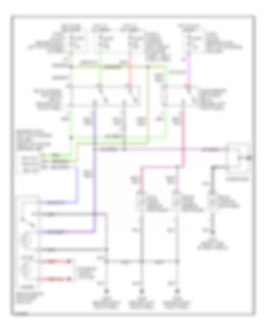
Horn Wiring Diagram for Infiniti G20 t 1999
List of elements for Horn Wiring Diagram for Infiniti G20 t 1999:
- Fuse & fusible link box (left front of engine compartment, next to battery)
- Fuse 36 10a
- Fuse 41 10a
- Horn high (right front of engine compartment)
- Horn high relay (in relay box)
- Horn low (right side of engine compartment)
- Horn low relay (in relay box)
- Horn switch
- Hot at all times
- Red
- Spiral cable (under steering wheel)
INSTRUMENT CLUSTER
Instrument Cluster Wiring Diagram (1 of 2) for Infiniti G20 t 1999
List of elements for Instrument Cluster Wiring Diagram (1 of 2) for Infiniti G20 t 1999:
- Abs ind
- Airbag ind
- Brake ind
- Charge ind
- Combination meter
- Door ind
- Door locks
- Exterior lights
- Flexible *
- Fuel gauge
- Fuel ind
- Fuel tank gauge unit (top of fuel tank)
- Fuse 11 10a
- Fuse 5 7.5a
- Fuse block (j/b) (behind dash, left of steering column)
- G101 (front of right front fender)
- G203 (behind right kick panel)
- G310 (behind right side trim panel of rear seat)
- Headlights
- Hot at all times
- Hot in on or start
- Interior lights
- Joint connector 3 (diode) (behind center of dash)
- Malfunction ind
- O/d off ind
- Odometer/trip meter) (with speedometer and
- Oil press ind
- Park/neutral position switch (on transaxle)
- Pnk
- Print circuit
- Red
- Seat belt ind
- Starting/ charging system
- Tachometer
- Thermal transmitter (on lower front of intake manifold)
- To combination meter (diagram 2 of 2)
- Unified meter control unit
- Vehicle speed sensor (on top right side of transaxle)
- Washer ind
- Water temp gauge
Instrument Cluster Wiring Diagram (2 of 2) for Infiniti G20 t 1999
List of elements for Instrument Cluster Wiring Diagram (2 of 2) for Infiniti G20 t 1999:
- 43k
- Abs control unit (behind right kick panel)
- Abs fail ind
- Air bag diagnosis sensor unit (below rear of center console)
- Air bag ind
- Brake fluid level switch (in brake fluid reservoir)
- Combination meter
- Cruise control system
- Diode
- Ecm (eccs) control module (behind center of dash)
- From combination meter (diagram 1 of 2)
- G102 (left front shock tower)
- Hi beam ind
- Illumination
- Left turn ind
- Mal ind driver
- O/d off
- Odo/trip illumination
- Oil pressure switch (on right front side of cylinder block)
- Parking brake switch
- Right turn ind
- Seat belt
- Tach out
- Transmission control module (behind lower center of dash)
- Voltage regulator
- Vsp in
- W/ daytime running lights
- W/o daytime running lights
- Washer level switch (fluid reservoir)
INTERIOR LIGHTS
Courtesy Lamps Wiring Diagram for Infiniti G20 t 1999
List of elements for Courtesy Lamps Wiring Diagram for Infiniti G20 t 1999:
- 11b
- Bat saver out
- Battery
- Circuit breaker 1 (behind dash, left of fuse block)
- Condition sw
- Diode (left front of luggage compt, taped to harness)
- Door
- Door sw (all)
- Door sw (dr)
- Door sw (pass)
- Fuse 10a
- Fuse block
- G200 (behind left kick panel)
- G203 (behind right kick panel)
- G308 (left "b" pillar)
- G310 (behind right side trim panel of rear seat)
- Ground
- Hot at all times
- Hot in on or start
- Ignition
- Interior room lamp
- Key switch
- Left front door lock actuator
- Left front door switch
- Left rear door switch
- Left vanity mirror
- Map lamp
- Off
- Passenger side front door switch
- Pnk
- Red
- Right rear door switch
- Right vanity mirror
- Room lamp out
- Smart entrance contrl unit (left of steering column)
- Trunk room lamp
- Trunk room lamp switch
Instrument Illumination Wiring Diagram for Infiniti G20 t 1999
List of elements for Instrument Illumination Wiring Diagram for Infiniti G20 t 1999:
- 11d
- 13h
- 4 bulbs
- A/c auto amp
- A/t device
- Ascd main switch
- Ashtray illum
- Audio
- Combination meter
- Fuse & fusible link box
- Fuse 10a
- Fuse block
- G200 (behind left kick panel)
- G203 (behind right kick panel)
- Glove box lamp
- Hazard switch
- Head
- Hot at all times
- Hot in on or start
- Illumination control switch
- Light switch
- Nca
- Od0/trip meter illumi- nation
- Off
- Park
- Power window main switch
- Push control unit
- Rear window defogger switch
- Red
- Voltage reg- ulator
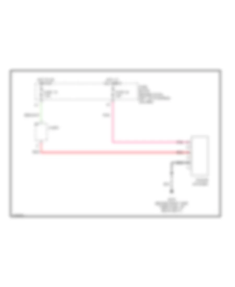
POWER ANTENNA
Power Antenna Wiring Diagram for Infiniti G20 t 1999
List of elements for Power Antenna Wiring Diagram for Infiniti G20 t 1999:
- Audio
- Fuse 10 7.5a
- Fuse 24 10a
- Fuse block (behind dash, left of steering column)
- G310 (behind right side trim panel of rear seat)
- Hot at all times
- Hot in on or acc
- Pnk
- Power antenna
- Red
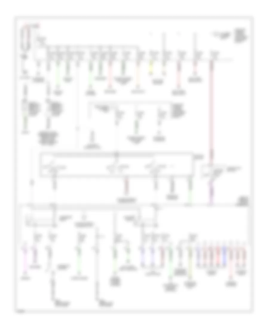
POWER DISTRIBUTION
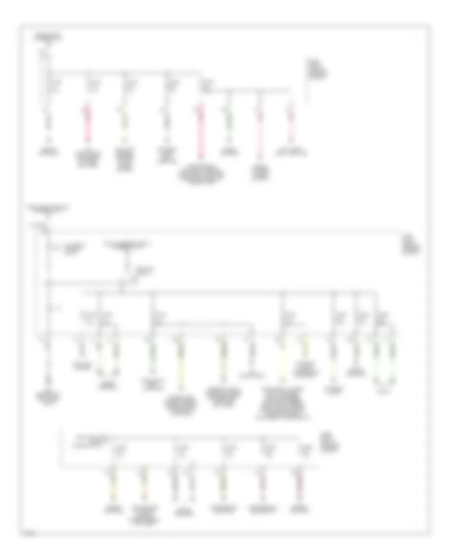
Power Distribution Wiring Diagram (1 of 2) for Infiniti G20 t 1999
List of elements for Power Distribution Wiring Diagram (1 of 2) for Infiniti G20 t 1999:
- (left of steering column) fuse block
- 11d
- 12d
- 14h
- 1st
- 2nd
- Acc
- Accessory relay
- Air conditioning
- Air conditioning, engine controls
- Anti-lock brakes
- Anti-theft body computer
- Anti-theft, headlights
- Battery
- Blower relay
- Cigarette lighter
- Circuit breaker 1 (behind dash, left of fuse block)
- Circuit breaker 2 (behind dash, left of fuse block)
- Combinaton switch
- Cooling fans
- Cruise control anti-theft horn
- Cruise control, anti-theft, horn
- Defogger
- Exterior lights
- From fuse 34 a (diagram 1 of 1)
- Fuse 10a
- Fuse 15a
- Fuse 20a
- Fuse 7.5a
- Fuse a 80a
- Fuse and fusible link box (left front of engine compt)
- Fuse b 40a
- Fuse c 40a
- Fuse d 30a
- Fuse e 100a
- Fuse f 40a
- Fuse g 40a
- Fuse h 40a
- G200 (behind left kick panel)
- G203 (behind right kick panel)
- Headlights
- Ignition switch
- Interior lights
- Interor lights, warning systems, power tops, door locks, power windows, anti-theft
- Lighting switch
- Mirrors
- Nca
- Off
- Red
- Seats
- Sound systems
- Sound systems, power antenna
- Start
- Starting/ charging
- Starting/ charging (m/t)
- Starting/ charging, headlights
- To fuse 4 (diagram 2 of 2)
- To fuse g (diagram 1 of 1)
- To ignition relay (diagram 2 of 2)
- Warning systems
- Wiper/washer
Power Distribution Wiring Diagram (2 of 2) for Infiniti G20 t 1999
List of elements for Power Distribution Wiring Diagram (2 of 2) for Infiniti G20 t 1999:
- 11b
- 12b
- 15d
- Air conditioning
- Air conditioning, instrument cluster, anti-theft
- Anti-lock brakes
- Anti-lock brakes, exterior lights, cruise control
- Anti-theft, body computer
- Cooling fans, starting/ charging, cruise control anti-theft
- Engine controls
- Exterior lights
- Exterior lights, body computer
- Exterior lights, transmission controls
- From accessory relay (diagram 1 of 2)
- From fuse a (diagram 1 of 2)
- From ignition e relay (diagram 2 of 2)
- From ignition switch (diagram 1 of 2)
- Fuse 10a
- Fuse 15a
- Fuse 7.5a
- Fuse block (left of steering column)
- G200 (behind left kick panel) dash)
- Headlights, body computer
- Ignition relay
- Interior lights, warning systems, defogger, body computer, anti-theft
- Pnk
- Power tops, power windows, cruise control, transmission controls
- Seats
- Sound systems
- Sound systems. power antenna
- To fuse 16 (diagram 2 of 2)
- Transmission controls
- Transmission controls, interior lights, body computer, integrated homelink transmitter
POWER DOOR LOCKS
Power Door Lock Wiring Diagram for Infiniti G20 t 1999
List of elements for Power Door Lock Wiring Diagram for Infiniti G20 t 1999:
- (2000)
- 11b
- Accessory
- Anti-theft system
- Battery (c/b)
- Battery (fuse)
- Battery saver out
- Between full stroke and n
- Central lock sw
- Central unlock sw
- Circuit breaker 1 (behind dash, left of fuse block)
- Door lock output
- Door switch
- Door unlock out
- Dr condition sw
- Dr door switch
- Dr door unlock out
- Exterior lights system
- Full stroke
- Fuse 10a
- Fuse 7.5a
- Fuse block (behind dash, left of steering column)
- G200 (behind left kick panel)
- G203 (behind right kick panel)
- G305 (right "b" pillar)
- G308 (left "b" pillar)
- Ground
- Hazard output
- Hot at all times
- Hot in acc or on
- Hot in on or start
- Ignition
- Interior lights system
- Key cyl sw lock
- Key cyl sw unlock
- Key switch
- Left front door key cylinder switch
- Left front door lock actuator
- Left front door switch
- Left rear door lock actuator
- Left rear door open switch
- Lock
- Locked
- Main power window & door lock switch
- Off
- Open
- Panic alarm output
- Pass condition sw
- Pass door switch
- Pnk
- Rear condition sw
- Right front door key cylinder switch
- Right front door lock actuator
- Right front door open switch
- Right rear door lock actuator
- Right rear door open switch
- Room lamp output
- Smart entrance control unit (behind dash, left of steering column)
- Unlock
- Unlocked
POWER MIRRORS
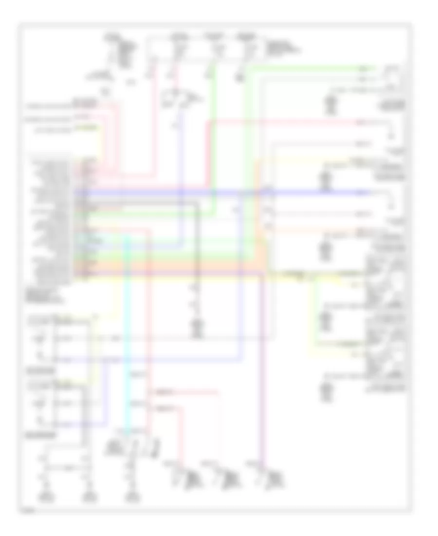
Power Mirror Wiring Diagram for Infiniti G20 t 1999
List of elements for Power Mirror Wiring Diagram for Infiniti G20 t 1999:
- Change over switch
- Door mirror remote control switch
- Driver's side door mirror actuator
- Fuse 9 10a
- Fuse block (left of steering column)
- G200 (behind left kick panel)
- Hot in on or acc
- Left/right motor
- Mirror switch
- Off
- Passenger's side door mirror actuator
- Up/down motor
POWER SEATS
Driver Power Seat Wiring Diagram for Infiniti G20 t 1999
List of elements for Driver Power Seat Wiring Diagram for Infiniti G20 t 1999:
- Circuit breaker 2 (behind dash, left of fuse block)
- Driver's power seat
- Driver's power seat switch
- Fwd
- G305 (right "b" pillar)
- G308 (left "b" pillar)
- Hot at all times
- Nca
- Reclining motor
- Reclining switch
- Red
- Rev
- Sliding motor
- Sliding switch
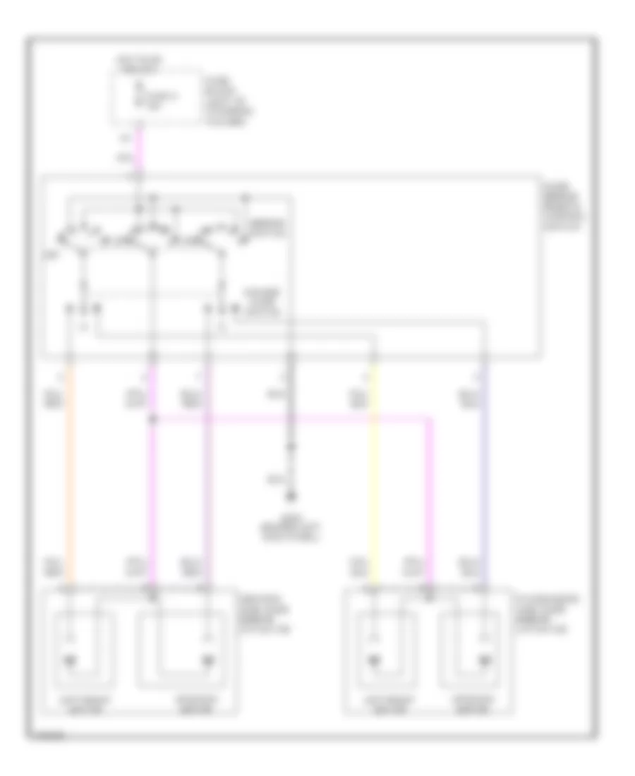
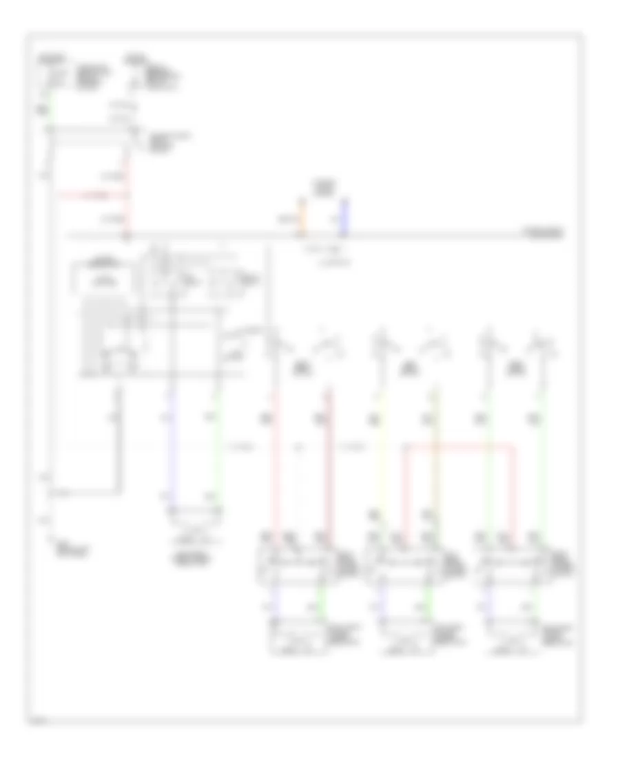
Heated Seats Wiring Diagram for Infiniti G20 t 1999
List of elements for Heated Seats Wiring Diagram for Infiniti G20 t 1999:
- 10f
- 11f
- Driver's heated seat switch
- Driver's seat back heater
- Fuse 28 10a
- Fuse block (behind dash, left of steering column)
- G305 (right "b" pillar)
- G308 (left "b" pillar)
- High
- Hot in on or start
- Indicator
- Low
- Nca
- Passenger's heated seat switch
- Passenger's seat back heater
- Pnk
- Red
- Seat back heater
- Seat cushion heater
- Seat cushion thermostat
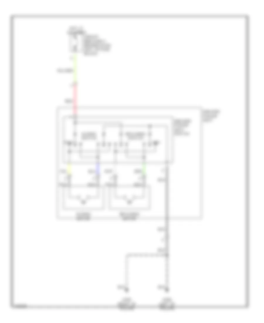
POWER TOP/SUNROOF
Power Top/Sunroof Wiring Diagrams for Infiniti G20 t 1999
List of elements for Power Top/Sunroof Wiring Diagrams for Infiniti G20 t 1999:
- 10b
- Circuit breaker 1 (behind dash, left of fuse box)
- Down/open
- Fuse 8 10a
- Fuse block (behind dash, left of steering column)
- G200 (behind left kick panel)
- G203 (behind right kick panel)
- Hot at all times
- Hot in on or start
- Power window relay (on fuse box)
- Red
- Sun roof motor (at front of sun roof opening)
- Sun roof switch
- Up/close
POWER WINDOWS
Power Window Wiring Diagram for Infiniti G20 t 1999
List of elements for Power Window Wiring Diagram for Infiniti G20 t 1999:
- 10b
- Auto amplifier
- Auto dn
- Auto up
- Circuit breaker 1 (behind dash, left of fuse block)
- Down
- Down relay
- Driver side switch
- Fuse 10a
- Fuse block (behind dash, left of steering column)
- G200 (behind left kick panel)
- Hot at all times
- Hot in on or start
- Illuminaton
- Interior lights system
- Left front power window regulator
- Left rear power window regulator
- Left rear power window switch
- Left rear switch
- Lock
- Lock switch
- Power window main switch
- Power window relay (on fuse block)
- Right front power window regulator
- Right front power window switch
- Right front switch
- Right rear power window regulator
- Right rear power window switch
- Right rear switch
- Unlock
- Up relay
RADIO
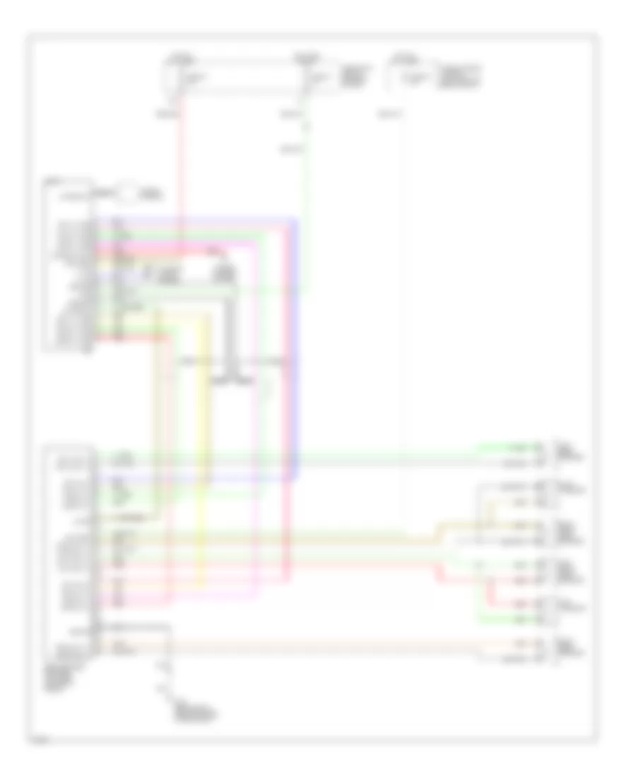
Radio Wiring Diagrams for Infiniti G20 t 1999
List of elements for Radio Wiring Diagrams for Infiniti G20 t 1999:
- 12b
- Acc
- Antenna ctrl
- Antenna in
- Audio
- Battery
- Battery
- Bose speaker amplifier (top front center of trunk)
- Fr lh (+) amp
- Fr lh (-) amp
- Fr lh in (+)
- Fr lh in (-)
- Fr lh out (+)
- Fr lh out (-)
- Fr rh (+) amp
- Fr rh (-) amp
- Fr rh in (+)
- Fr rh in (-)
- Fr rh out (+)
- Fr rh out (-)
- Fuse & fusible link box (left front of engine compt)
- Fuse 10 7.5
- Fuse 24 10a
- Fuse 38 15a
- Fuse block (left of steering column)
- G310 (behnd right side trim panel of rear seat)
- Ground
- Ground
- Hot at all times
- Hot in on or acc
- Illum
- Illum
- Interior lights system
- Left front door speaker
- Left rear speaker
- Left tweeter
- Nca
- On sig
- On signal
- Pnk
- Power antenna system
- Red
- Right front door speaker
- Right rear speaker
- Right tweeter
- Rr lh (+) amp
- Rr lh (-) amp
- Rr lh in (+)
- Rr lh in (-)
- Rr lh out (+)
- Rr lh out (-)
- Rr rh (+) amp
- Rr rh (-) amp
- Rr rh in (+)
- Rr rh in (-)
- Rr rh out (+)
- Rr rh out (-)
- Window antenna
SHIFT INTERLOCKS
Shift Interlock Wiring Diagram for Infiniti G20 t 1999
List of elements for Shift Interlock Wiring Diagram for Infiniti G20 t 1999:
- 10b
- A/t device (under center console, at base of selector lever)
- Ascd brake switch (on bracket, above brake pedal)
- Fuse 8 10a
- Fuse block (left of steering colulmn)
- G200 (behind left kick panel)
- G203 (behind right kick panel)
- Hot in on or start
- Nca
- Park position switch
- Red
- Shift lock solenoid
STARTING/CHARGING
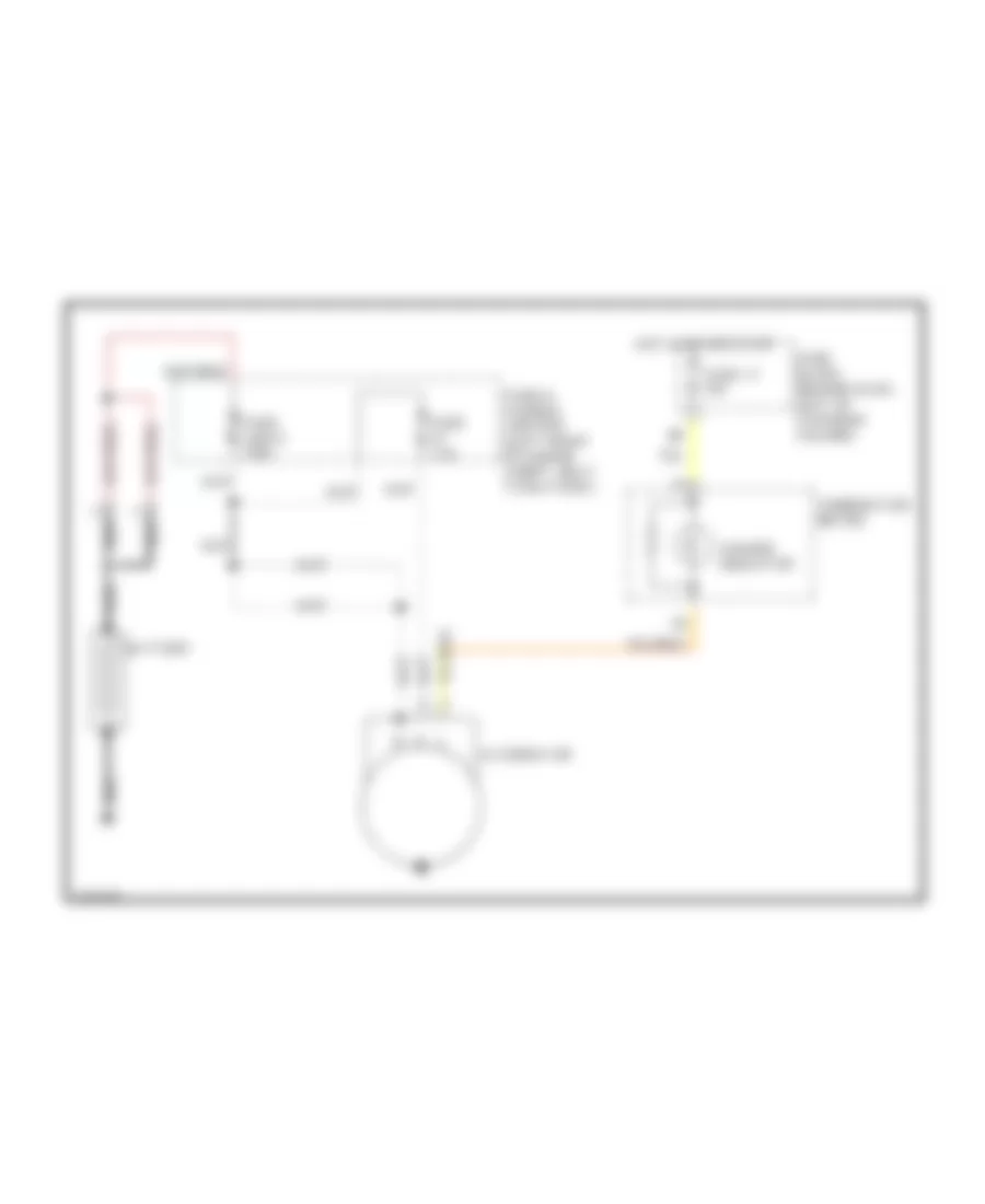
Charging Wiring Diagram for Infiniti G20 t 1999
List of elements for Charging Wiring Diagram for Infiniti G20 t 1999:
- Alternator
- Battery
- Charge indicator
- Combination meter
- Fuse & fusible link box (left front of engine compt, next to battery)
- Fuse 11 10a
- Fuse 7.5a
- Fuse block (behind dash, left of steering column)
- Fuse link e 100a
- Hot in on or start
- Nca
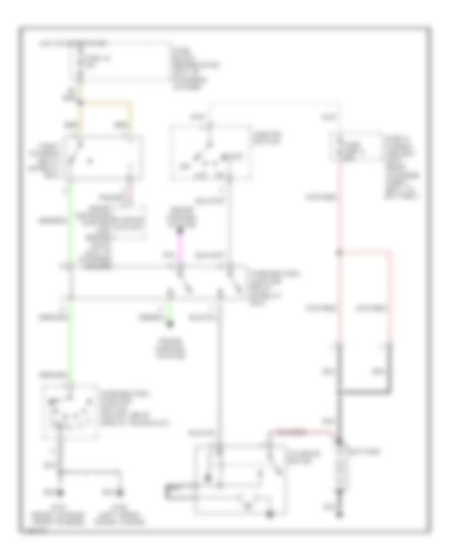
Starting Wiring Diagram, A/T for Infiniti G20 t 1999
List of elements for Starting Wiring Diagram, A/T for Infiniti G20 t 1999:
- Acc
- Battery
- Cruise control system
- Fuse & fusible link box (left front of engine compt, next to battery)
- Fuse 16 10a
- Fuse block (behind dash, left of steering column)
- Fuse link g 40a
- G101 (front of right front fender)
- G102 (left front shock tower)
- Hot in on or start
- Ignition switch
- Nca
- Off
- Park/neutral position relay (in relay box)
- Park/neutral position switch (on left rear side of transaxle)
- Smart entrance control unit (behind dash, left of steering column)
- Start
- Starter cutout
- Starter motor
- Theft warning relay (in relay box)
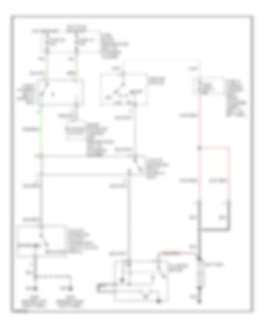
Starting Wiring Diagram, M/T for Infiniti G20 t 1999
List of elements for Starting Wiring Diagram, M/T for Infiniti G20 t 1999:
- 11h
- Acc
- Battery
- Clutch interlock relay (in relay box)
- Clutch interlock switch (on bracket, above clutch pedal)
- Depressed
- Fuse & fusible link box (left front of engine compt, next to battery)
- Fuse 16 10a
- Fuse 26 10a
- Fuse block (behind dash, left of steering column)
- Fuse link g 40a
- G200 (behind left kick panel)
- G203 (behind right kick panel)
- Hot in on or start
- Hot in start
- Ignition switch
- Nca
- Off
- Released
- Smart entrance control unit (behind dash, left of steering column)
- Start
- Starter cutout
- Starter motor
- Theft warning relay (in relay box)
SUPPLEMENTAL RESTRAINTS
Supplemental Restraint Wiring Diagram for Infiniti G20 t 1999
List of elements for Supplemental Restraint Wiring Diagram for Infiniti G20 t 1999:
- (at base of left "b" pillar) g308
- (left kick panel) g200
- Air bag diagnosis sensor unit (below rear of center console)
- Air bag indicator
- Air bag w/l
- B19
- Closed
- Combination meter
- Data link connector (dlc) (consult) (partial) (at left side of dash, behind fuse box cover)
- Detection conn
- Door switch
- Driver side air bag module
- Driver side front door switch
- Driver side seat belt pre-tensioner
- Fastened
- Fuse 11 10a
- Fuse 22 10a
- Fuse block (behind dash, left of steering column)
- G305 (at base of right "b" pillar)
- G308 (at base of left "b" pillar)
- Ground
- Hot in on or start
- Ignition
- Left satellite sensor (at base of left "b" pillar)
- Left side air bag module
- M40
- M41
- Nca
- Open
- Passenger side air bag module
- Passenger side seat belt pre-tensioner
- Right satellite sensor (at base of right "b" pillar)
- Right side air bag module
- Sat l +
- Sat l -
- Sat r +
- Sat r -
- Seat belt buckle switch (in driver's seat belt buckle)
- Seat belt indicator
- Seat belt sw
- Seat belt w/l
- Spiral cable
- Sq as +
- Sq as -
- Sq dr +
- Sq dr -
- Sq pas +
- Sq pas -
- Sq pdr +
- Sq pdr -
- Sq side l +
- Sq side l -
- Sq side r +
- Sq side r -
- Un- fastened
TRANSMISSION
A/T Wiring Diagram for Infiniti G20 t 1999
List of elements for A/T Wiring Diagram for Infiniti G20 t 1999:
- (at left side of dash, behind fuse box cover) data link connector (for consult)
- (left rear side trnsaxle) park/neutral position switch
- 1-sw
- 10h
- 11b
- 2-sw
- A/t device (overdrive control switch) (under center console, at base of selector lever)
- A/t fluid temp sensor
- Acsd
- Acsd 4th
- All times
- Ascd control unit (behind dash, left of steering column)
- Atck
- Automatic transaxle
- Avcc
- Closed throttle
- Combination meter
- D-sw
- Diodes (behind center of dash, taped to harn)
- Dropping resistor (on left front of eng compt)
- Dt1
- Dt2
- Dt3
- Eng/rev
- Engine control module (ecm) (behind center of dash, at lower left side of glove box)
- Fld temp
- Full sw
- Fuse 10a
- Fuse 21 10a
- Fuse 7 10a
- Fuse block (behind dash, left of steering column)
- G101 (front of right front fender)
- G134 (top of engine)
- G203 (behind right kick panel)
- Gnd
- Gnd-a
- Hot at
- Hot in on or start
- Idle sw
- J/c 1 (behind right side of dash, taped to harn)
- Line press sol valve
- Lu duty
- Mem b/u
- N-sw
- Nca
- O/d ind
- O/d off ind
- O/d sw
- Odb2
- Over- run clutch sol
- Ovr/c
- Pl duty
- Pnk
- R-sw
- Red
- Revolution sensor (right rear side of transaxle)
- Sen pwr
- Sens gnd
- Shift a
- Shift b
- Shift sol valve a
- Shift sol valve b
- Sss in
- Sss out
- Tacho
- Tcc sol valve
- Th sens
- Throttle position switch (on throttle body assembly)
- Transmission control module (tcm) (behind lower center of dash, forward of selector lever)
- Tvo1
- Tvoo
- Unified meter control unit
- Vehicle speed sensor (top right side of transaxle)
- Vign
- Vsp
- Vsp-1
- Vsp-2
- Wot
WARNING SYSTEMS
Warning System Wiring Diagrams for Infiniti G20 t 1999
List of elements for Warning System Wiring Diagrams for Infiniti G20 t 1999:
- 12d
- 13h
- Battery (c/b)
- Circuit breaker 1 (behind dash, left of fuse block)
- Dr door sw
- Fuse 10a
- Fuse block (behind dash, left of steering column)
- G200 (behind left kick panel)
- G305 (right "b" pillar)
- G308 (left "b" pillar)
- Ground
- Head
- Hot at all times
- Hot in on or start
- Ignition
- Key sw
- Key switch
- Left front door switch
- Light sw
- Lighting switch
- Off
- Park
- Pnk
- Seat belt buckle switch
- Seat belt sw
- Smart entrance control unit (behind dash, left of steering column)
WIPER/WASHER
Wiper/Washer Wiring Diagram for Infiniti G20 t 1999
List of elements for Wiper/Washer Wiring Diagram for Infiniti G20 t 1999:
- Front washer motor (on washer fluid reservoir)
- Front wiper motor (right side of firewall)
- Front wiper switch
- Fuse 19 20a
- Fuse block (left of steering column)
- G102 (left front shock tower)
- G203 (behind right kick panel)
- High
- Hot in run or accy
- Int
- Low
- Off
- Pnk
- Variable intermittent wiper control
- Wash
- Wiper amplifier

 Čeština
 Dansk
Dansk Deutsch
 Ελληνικά
 English
 English
 Español
 Suomi
Suomi Français
 Français
 עברית
עברית Hrvatski
 Magyar
 Italiano
 日本語
日本語 한국어
한국어 Nederlands
 Polski
 Português
 Română
 Русский
 Slovenčina
 Slovenščina
 Svenska
 Türkçe
 中文 (中国)