AIR CONDITIONING
3.5L
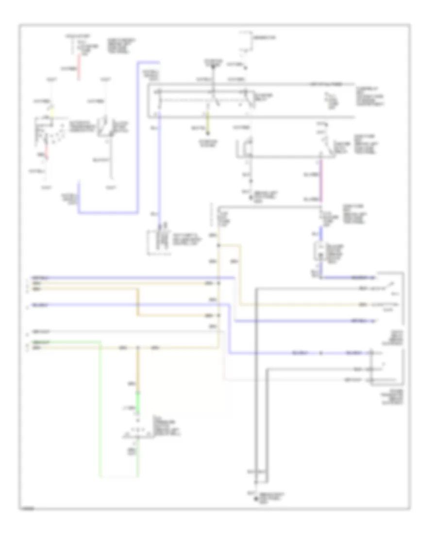
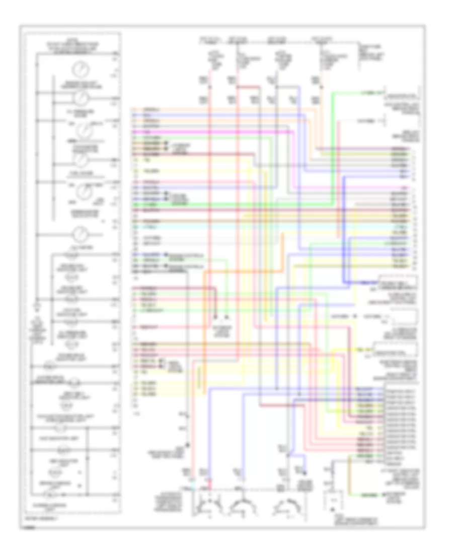
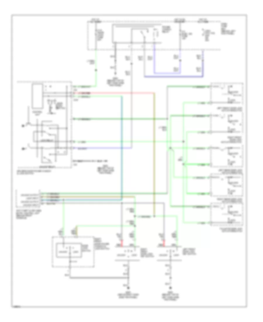
3.5L, Automatic A/C Wiring Diagram (1 of 2) for Isuzu Trooper Limited 2000
 https://portal-diagnostov.com/license.html
Automotive Electricians Portal FZCO
Automotive Electricians Portal FZCO
https://portal-diagnostov.com/license.html
https://portal-diagnostov.com/license.html
Automotive Electricians Portal FZCO
Automotive Electricians Portal FZCO
List of elements for 3.5L, Automatic A/C Wiring Diagram (1 of 2) for Isuzu Trooper Limited 2000:
- (behind glove box)
- (behind right kick panel) g203
- 5v ref
- A/c c rly ctl
- A/c compressor
- A/c compressor relay
- A/c on input
- A/c t rly ctl
- A/c thermostat relay
- Automatic heater-a/c control unit (center of dash)
- B/l
- B/l control
- Battery
- Blow spd ctl
- Blow spd in
- C-16 clock/ dome fuse 10a
- C-h control
- Clutch
- Cold/hot in
- D-v control
- D/f
- Dash fuse box (behind left dash side trim panel)
- Def
- Def control
- E19
- E21
- Ect sensor
- Engine controls system
- Engine or powertrain control module (pcm) (on right side of engine compartment)
- Evap temp in
- Evaporator sensor (behind glove box)
- Foot
- Fresh
- Fresh pos in
- Ft/recir ctl
- Fuse/relay box (on right side of engine compartment)
- Ground
- H-c control
- Hi bw spd ctl
- Hot at all times
- I32
- I33
- Ignition input
- Illum ctl (+)
- Illum ctl (-)
- In-car temperature sensor (center of dash)
- Inside temp in
- Instrument cluster system
- Intake actuator
- Interior lights system
- Mix
- Mix actuator
- Mix pos in
- Mode actuator (above left dash side trim panel)
- Out temp in
- Outside temperature sensor (behind left side of grill)
- Rec
- Rec pos in
- Rec/fresh ctl
- Recirc
- Sensor gnd
- Sun sens in
- Sunlight sensor
- Thermo sensor (top front of engine)
- V-d control
- Vent
- Vent d/f ctl
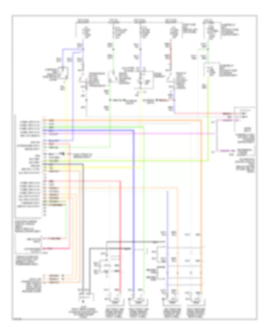
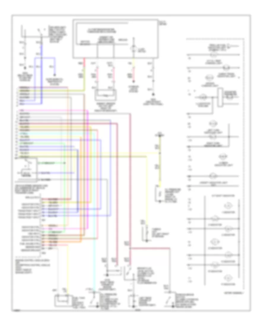
3.5L, Automatic A/C Wiring Diagram (2 of 2) for Isuzu Trooper Limited 2000
List of elements for 3.5L, Automatic A/C Wiring Diagram (2 of 2) for Isuzu Trooper Limited 2000:
- (behind left kick panel) g200
- (behind right kick panel) g203
- A/c pressure switch (behind left side of grill)
- Anti-theft & keyless entry control unit
- Automatic transmission mode switch
- B20 control
- Blower motor (behind glove box)
- C-1 starter fuse 10a
- C-19 blower fuse 25a
- C-20 a/c fuse 10a
- Clutch start switch
- Dash fuse box (behind left dash side trim panel)
- Fl-1 main fuse 80a
- Fuse/relay box (on right side of engine compartment)
- Generator
- Heater & a/c relay
- Hot at all times
- Hot in start
- Max-hi relay (behind glove box)
- Power transistor (behind glove box)
- Red
- Starter relay
- Starting system
- W/a/t
- W/m/t
ANTI-LOCK BRAKES
Anti-lock Brake Wiring Diagrams for Isuzu Trooper Limited 2000
List of elements for Anti-lock Brake Wiring Diagrams for Isuzu Trooper Limited 2000:
- "abs" ind
- (ls/limited)
- (right front of engine compt)
- (s model)
- 4wd engaged input
- 4wd engaged output
- A/t
- Abs active input
- Abs active output
- Abs ind lt ctrl
- B-48
- Back-up light switch (on right side of trans- mission)
- Battery
- Braided wire
- Brake input
- Brake switch (on brake pedal support)
- C-10 meter gauge fuse 10a
- C-14 stoplight a/t cont fuse 15a
- C-3 turn/ back fuse 15a
- C-4 elec ign fuse 15a
- Connector (dlc) (left side of dash, above engine hood release lever)
- Dash fuse box (behind left kick panel)
- Data link
- Diode box a
- Dlc input/output
- E-22
- Electronic brake control module (ebcm) (right front of engine compartment)
- Exterior lights
- F-9 abs fuse 20a
- Fl-6 (abs 4/wheel only) fuse 40a
- Fuse/relay box (on right side of engine compartment)
- G sensor input
- G sensor- abs (rear of park brake lever)
- G101
- G105 (right rear corner of engine compartment, on inner fender panel)
- Gnd
- Ground
- Hot at all times
- Hot in on or start
- I-10
- I-9 i-9
- Ignition
- Left front abs speed sensor (inside of left front wheel)
- Left rear abs speed sensor (inside of left rear wheel)
- M/t
- Meter assembly
- Nca
- Pnk
- Powertrain control module (pcm) (behind center of dash, below radio)
- Red
- Rev/low gear in
- Reverse or l range output
- Right front abs speed sensor (inside of right front wheel)
- Right rear abs speed sensor (inside of right rear wheel)
- Torque on demand (tod) control unit (beneath front passenger's seat)
- Transmission switch 1st/2nd (on right front of transmission)
- Wheel spd in (hi)
- Wheel spd in (lo)
ANTI-THEFT
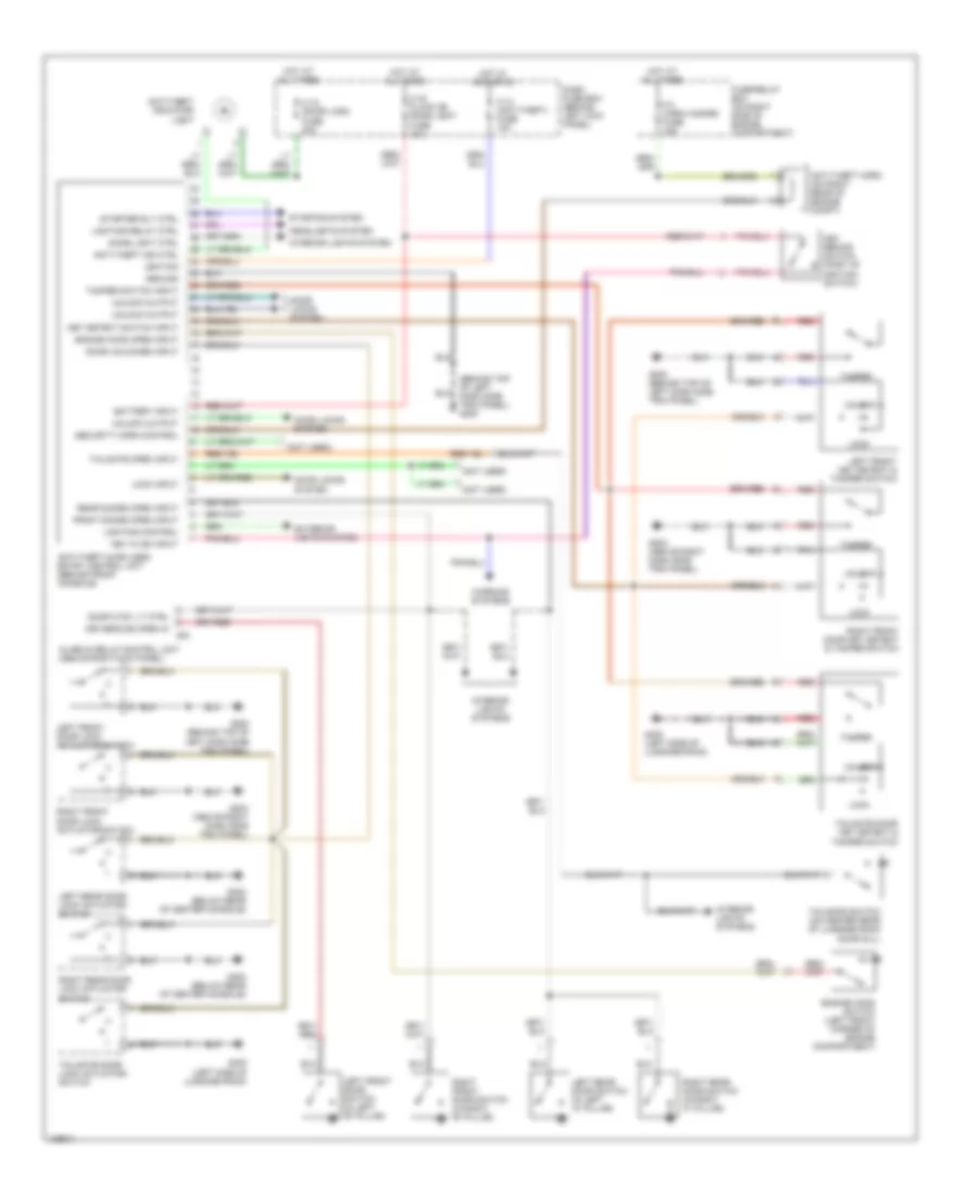
Anti-theft Wiring Diagram for Isuzu Trooper Limited 2000
List of elements for Anti-theft Wiring Diagram for Isuzu Trooper Limited 2000:
- (behind top of left dash side trim panel) g200
- (not used)
- Alarm & relay control unit (above right kick panel)
- Anti-theft & keyless entry control unit (behind front console)
- Anti-theft horn (on right rear of engine compt)
- Anti-theft ind ctrl
- Anti-theft indicator light
- B-6
- Battery input
- C-13 (anti-theft) fuse 10a
- C-16 clock (b) dome light fuse 10a
- C-18 (door lock) fuse 20a
- Dash fuse box (behind left kick panel)
- Dome light ctrl
- Door ctsy lt ctrl
- Door locks system
- Door unlocked input
- Driver's dr open in
- Engine hood open input
- Engine hood switch (left front corner of engine compartment)
- Exterior lights system
- F-3 horn hazard fuse 15a
- Front doors open input
- Fuse/relay box (on right side of engine compartment)
- G200 (behind top of left dash side trim panel)
- G203 (above right dash sdie trim panel)
- G302 (below rear of center console)
- G400 (left side of luggage room)
- Ground
- Headlights system
- Hot at all times
- Hot in acc or on
- Ignition
- Interior lights system
- Interior lights systems
- Key detect switch input
- Key in ign input
- Key remind switch (part of ignition switch)
- Left front door lock actuator/switch
- Left front door switch (in left "b" pillar)
- Left front key detect & tamper switch
- Left rear door lock actuator/ switch
- Left rear door switch (in left "c" pillar)
- Lighting control
- Lighting relay ctrl
- Lock
- Lock input
- Rear doors open input
- Red
- Right front door key detect & tamper switch
- Right front door lock actuator/switch
- Right front door switch (in right "b" pillar)
- Right rear door lock actuator/ switch
- Right rear door switch (in right "c" pillar)
- Security horn control
- Starter rly ctrl
- Starting system
- Tailgate door key detect & tamper switch
- Tailgate door lock actuator/ switch
- Tailgate open input
- Tailgate switch (on center rear of luggage room door sill)
- Tamper
- Tamper switch input
- Unlock
- Unlock output
- Warning systems
BODY COMPUTER
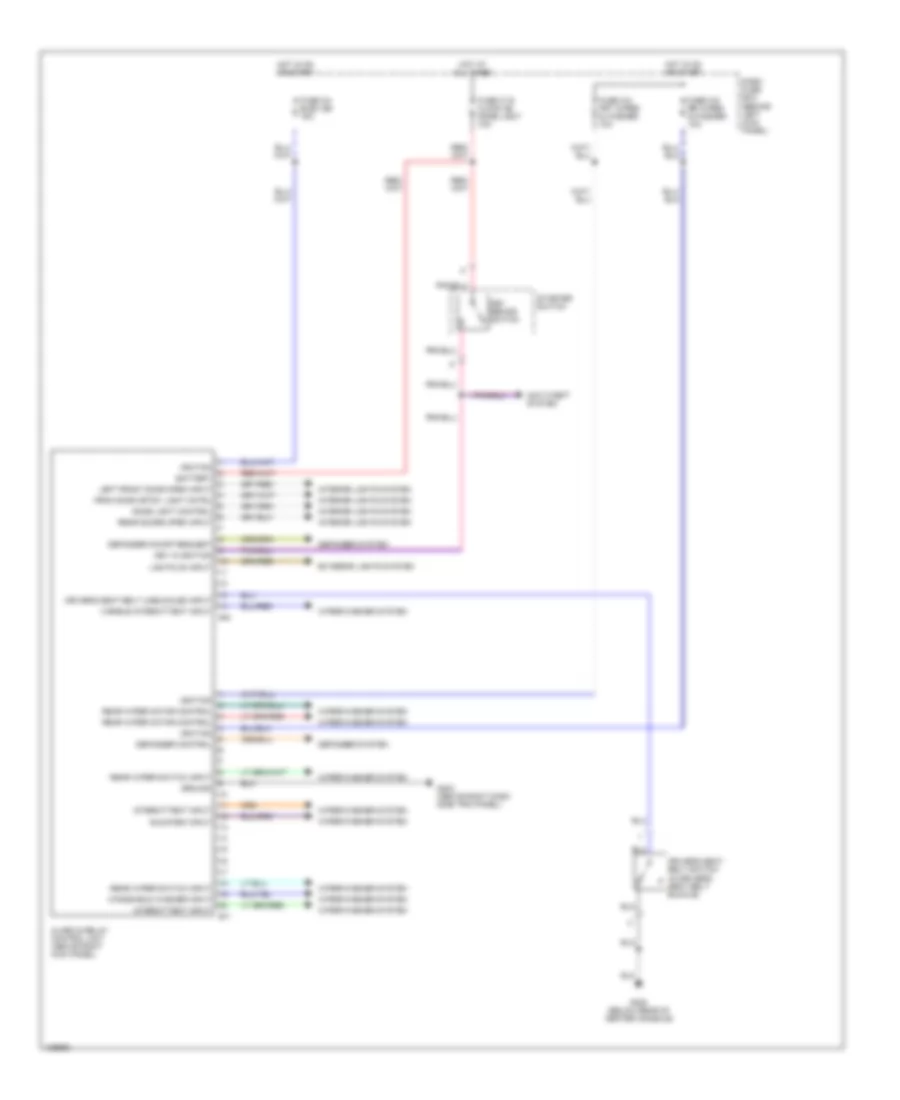
Body Computer Wiring Diagrams for Isuzu Trooper Limited 2000
List of elements for Body Computer Wiring Diagrams for Isuzu Trooper Limited 2000:
- Alarm & relay control unit (above right kick panel)
- Anti-theft system
- B-6
- B-7
- Battery
- Dash fuse box (behind left kick panel)
- Defogger control
- Defogger on/off request
- Defogger system
- Dome light control
- Driver's seat belt switch (in driver's seat belt buckle)
- Driver's seat belt unbuckled input
- Exterior lights system
- Fron door crtsy light cntrl
- Fuse c-16 clock (b) dome light 10a
- Fuse c-4 elec ign 15a
- Fuse c-6 frt wiper & washer 10a
- Fuse c-6 rr wiper & washer 10a
- G203 (above right dash side trim panel)
- G302 (below rear of center console)
- Ground
- Hot at all times
- Hot in on or start
- Ignition
- Interior lights system
- Intermittent input
- Key in ignition
- Key remind switch
- Left front door open input
- Lights on input
- Rear doors open input
- Rear wiper motor control
- Rear wiper switch input
- Run/park input
- Starter switch
- Varible intermittent input
- Windshield washer input
- Wiper/washer system
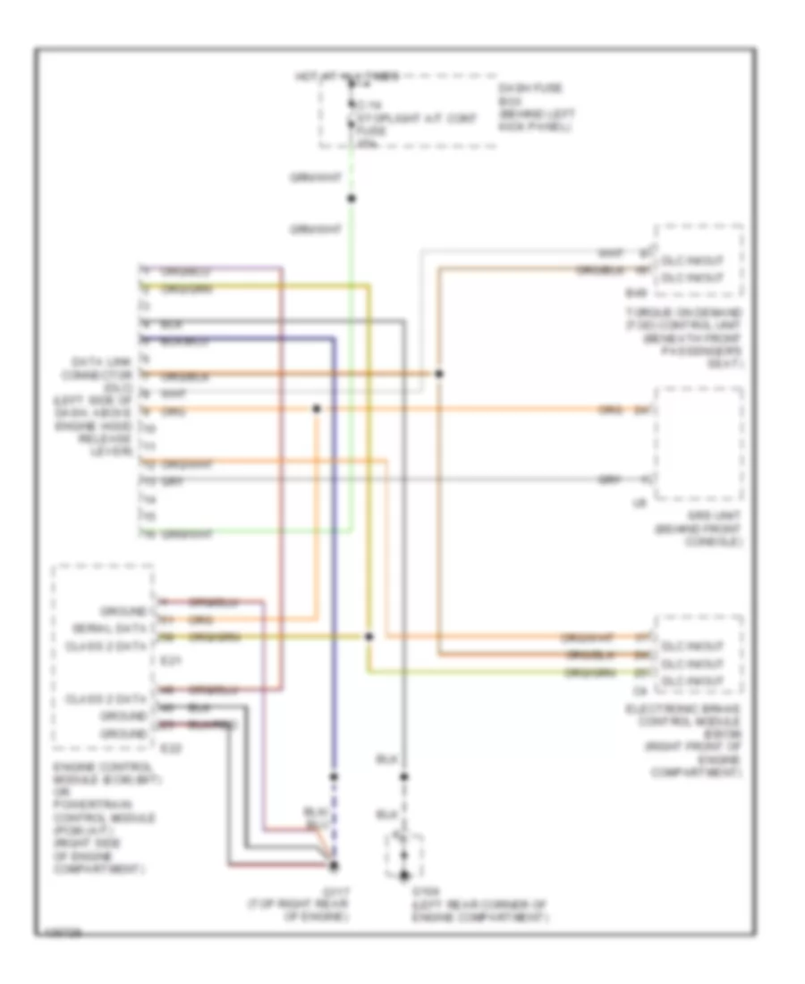
COMPUTER DATA LINES
Computer Data Lines for Isuzu Trooper Limited 2000
List of elements for Computer Data Lines for Isuzu Trooper Limited 2000:
- (dlc) (left side of dash, above engine hood
- B49
- C-14 stoplight a/t cont fuse 15a
- Class 2 data
- Dash fuse box (behind left kick panel)
- Data link connector
- Dlc in/out
- E21
- E22
- Electronic brake control module (ebcm) (right front of engine compartment)
- Engine control module (ecm) (m/t) or powertrain control module (pcm) (a/t) (right side of engine compartment)
- G104 (left rear corner of engine compartment)
- G117 (top right rear of engine)
- Ground
- Hot at all times
- Release lever)
- Serial data
- Srs unit (behind front console)
- Torque on demand (tod) control unit (beneath front passenger's seat)
CRUISE CONTROL
Cruise Control Wiring Diagram (1 of 2) for Isuzu Trooper Limited 2000
List of elements for Cruise Control Wiring Diagram (1 of 2) for Isuzu Trooper Limited 2000:
- (top left rear of engine) g114
- 5v ref
- Aps 1 input
- Aps 2 input
- Aps 3 input
- Automatic transmission mode switch (left side of transmission)
- Brake sw in
- Brake switch (on brake pedal support)
- Brake/tcc in
- C-10 meter gauge fuse 10a
- C-14 stoplight a/t cont fuse 15a
- C-3 back turn fuse 15a
- C-4 elec ign fuse 15a
- C-8 engine fuse 15a
- Cancel
- Cancel input
- Clutch switch (on clutch pedal support)
- Combination switch
- Cruise control main switch
- Cruise control switch
- Cruise main indicator light
- Cruise set indicator light
- Dash fuse box (behind left kick panel)
- Drive input
- E-21
- E-22
- Ecm or pcm (right side of engine compt)
- G105 (right rear corner of engine compt, on inner fender panel)
- G114 (top left rear of engine)
- G117 (top right rear of engine)
- Ground
- Hot at all times
- Hot in on or start
- I-9
- Ignition
- Illumination
- Indicator control
- Interior lights system
- Meter assembly
- On input
- Other
- Red
- Reference
- Resume/ accel
- Resume/accel input
- S model
- Sensor ground
- Set/ coast
- Set/coast input
- Tps 1
- Tps 2
- Valve motor +
- Valve motor -
- Vehicle speed sensor (on underside of vehicle, right rear of front transfer case)
- Vss input
Cruise Control Wiring Diagram (2 of 2) for Isuzu Trooper Limited 2000
List of elements for Cruise Control Wiring Diagram (2 of 2) for Isuzu Trooper Limited 2000:
- Acceleration position sensor 1
- Acceleration position sensor 2
- Acceleration position sensor 3
- Acceleration position sensor assembly
- Braided wire
- Ecm or pcm main relay
- Fl-3 ecm fuse 30a
- Fuse/ relay box (on right side of engine compt)
- G105 (right rear corner of engine compt, on inner fender panel)
- G114 (top left rear of engine)
- G117 (top right rear of engine)
- Hot at all times
- Nca
- Red
- Throttle position sensor 1
- Throttle position sensor 2
- Throttle valve assembly
- Throttle valve motor
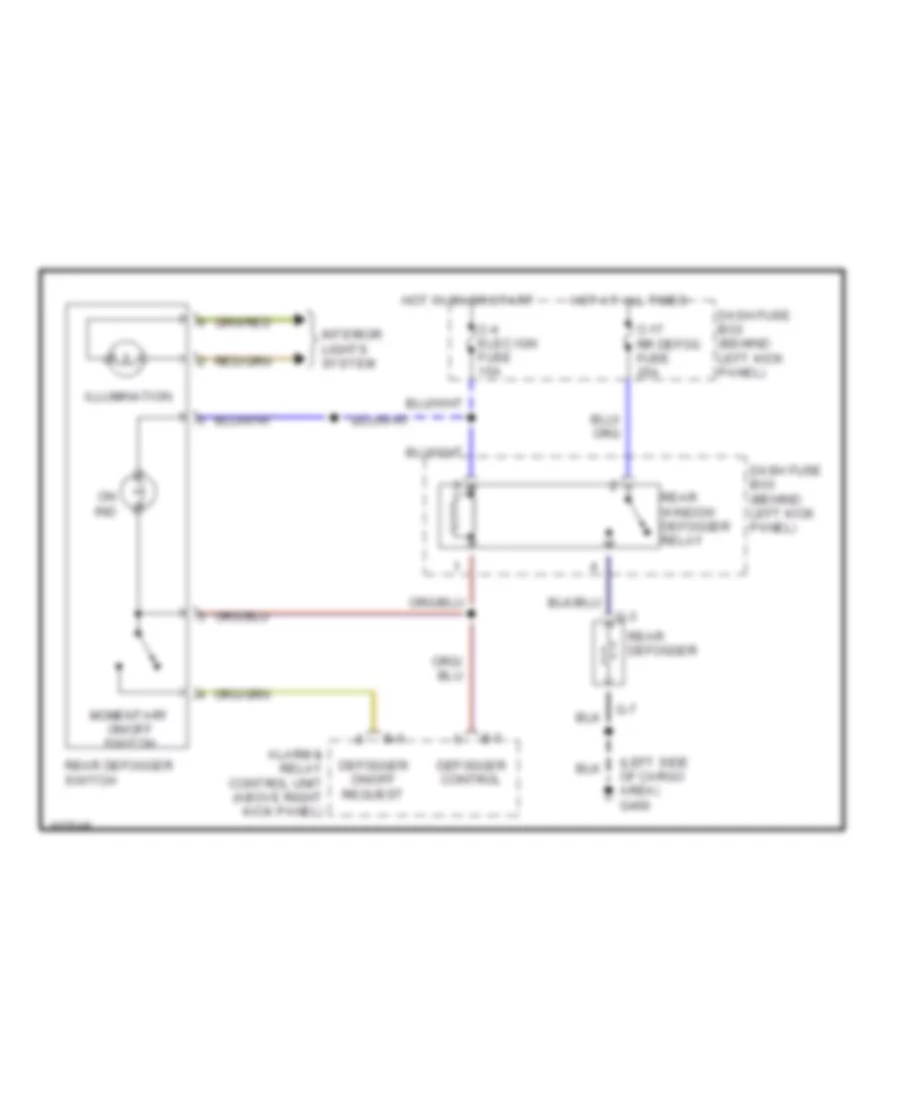
DEFOGGERS
Defogger Wiring Diagram for Isuzu Trooper Limited 2000
List of elements for Defogger Wiring Diagram for Isuzu Trooper Limited 2000:
- (left side of cargo area) g400
- Alarm & relay control unit (above right kick panel)
- B-6
- B-7
- C-17 rr defog fuse 25a
- C-4 elec ign fuse 15a
- Dash fuse box (behind left kick panel)
- Defogger control
- Defogger on/off request
- G-3
- G-7
- Hot at all times
- Hot in on or start
- Illumination
- Interior lights system
- Momentary on/off switch
- On ind
- Rear defogger
- Rear defogger switch
- Rear window defogger relay
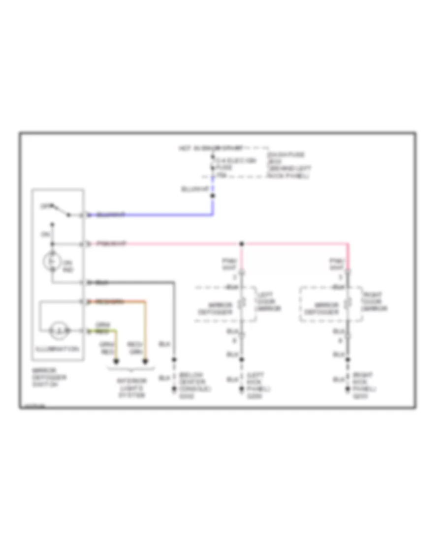
Heated Mirrors Wiring Diagram for Isuzu Trooper Limited 2000
List of elements for Heated Mirrors Wiring Diagram for Isuzu Trooper Limited 2000:
- (below center console) g302
- (left kick panel) g200
- (right kick panel) g203
- C-4 elec ign fuse 15a
- Dash fuse box (behind left kick panel)
- Hot in on or start
- Illumination
- Interior lights system
- Left door mirror
- Mirror defogger
- Mirror defogger switch
- Off
- On ind
- Right door mirror
ENGINE PERFORMANCE
3.5L
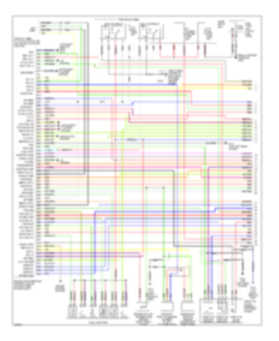
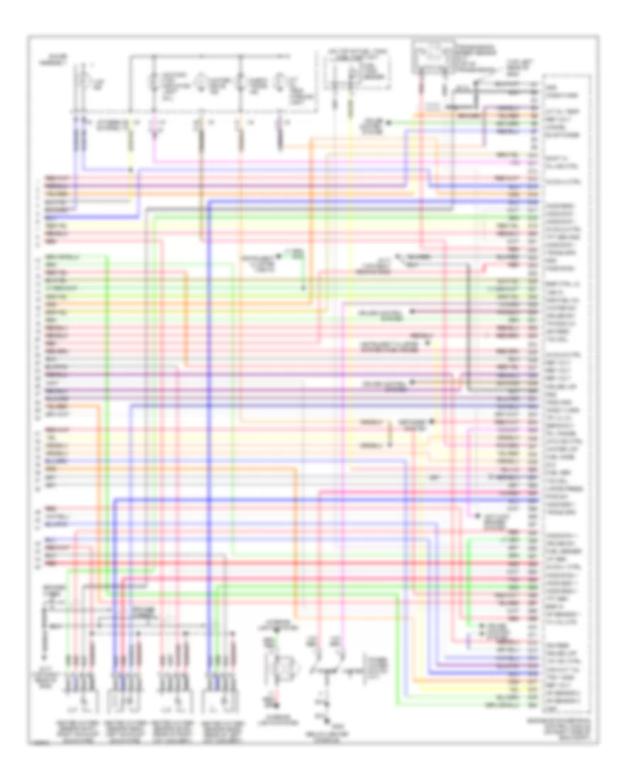
3.5L, Engine Performance Wiring Diagrams (1 of 4) for Isuzu Trooper Limited 2000
List of elements for 3.5L, Engine Performance Wiring Diagrams (1 of 4) for Isuzu Trooper Limited 2000:
- (below center console) g302
- (right rear corner of eng compt, on inner fender panel)
- (top right rear of eng) g117
- A/c clutch
- A/c req
- A/c system
- Adaptor case
- Ap sen1 gnd
- Ap sen2 gnd
- Braided
- Brake sw in
- C.q. sign in
- Camshaft position sensor (on rear of left cylinder head)
- Ckp in
- Clut or mode
- Cmp in
- Crankshaft position sensor (lower right side of eng)
- Cruise brake
- Cruise control system
- Ect in
- Eng speed
- Engine coolant temperature sensor (right front of eng)
- Engine or powertrain control module (on right side of eng compt)
- Etc gnd
- F-10 fuel pump fuse 15a
- F-2 o2 sens heater fuse 20a
- F10
- F12
- F14
- F17
- F18
- F19
- F20
- F23
- F25
- F26
- F27
- F29
- F31
- F32
- F33
- F37
- F38
- F39
- F40
- F41
- F42
- F43
- F44
- F45
- F46
- F47
- F48
- F49
- F50
- F51
- F52
- F53
- F54
- F56
- F57
- F58
- F60
- F61
- F62
- F63
- F64
- F65
- F66
- F67
- F68
- F69
- F70
- F71
- F72
- F73
- F74
- F75
- F76
- F77
- F78
- F79
- F80
- Fl-3 ecm fuse 30a
- Fuel injectors
- Fuel pump
- Fuel pump relay
- Fuel tank unit (top of fuel tank)
- Fuse/ relay box
- G105
- G114 (top left rear of eng)
- G117 (top right rear of eng)
- Gnd
- Headlights system
- Ho2s b1s2 -
- Ho2s b2s1 -
- Ho2s b2s2 -
- Ho2s2 h gnd
- Hot at all times
- Iat in
- Ig coil2 ctrl
- Ig coil3 ctrl
- Ign feed
- Illum sw
- Instrument cluster system
- Knock sig in
- Ks 1 in
- Ks 2 in
- Low fuel ind
- Maf in
- Map in
- Mode sw
- N01 fuel inj
- N02 fuel inj
- N03 fuel inj
- N04 fuel inj
- N05 inj ctrl
- Not used
- Pcm main relay
- Pins not used: f11 f13 f15 f16 f21 f22 f24 f28 f30 f34 f35 f36 f55 & f59
- Psp sw in
- Pwr drive ind
- Red
- Red pwr ind
- Ref volt
- Res/acc in
- Serial data
- Shield wire
- Shift sol a
- Throttle position sensor 1
- Throttle position sensor 2
- Throttle val
- Throttle valve assembly (top front of eng)
- Throttle valve motor
- Tps1 gnd
- Tps2 gnd
- Tps2 sign
- Vapor sen
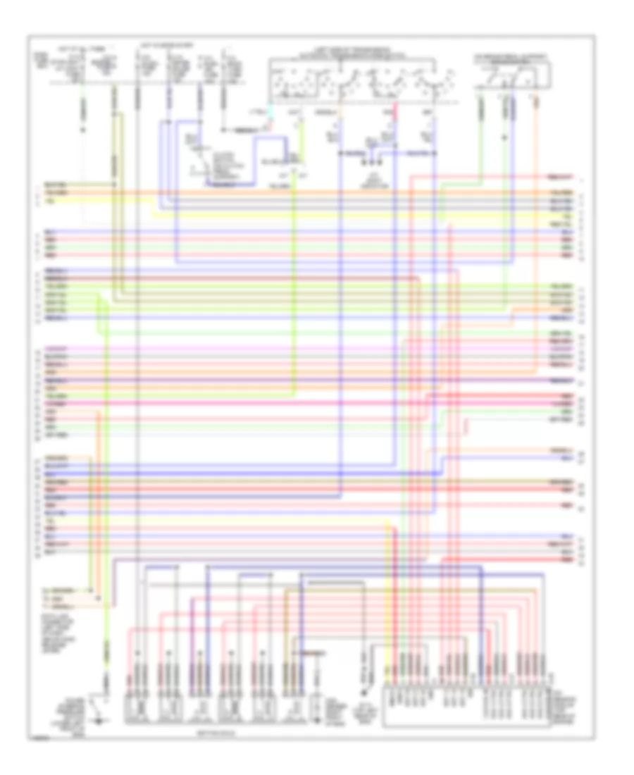
3.5L, Engine Performance Wiring Diagrams (2 of 4) for Isuzu Trooper Limited 2000
List of elements for 3.5L, Engine Performance Wiring Diagrams (2 of 4) for Isuzu Trooper Limited 2000:
- (left side of transmission) automatic transmission mode switch
- (on brake pedal support) brake switch
- 1,3,5 coil in
- 2,4,6 coil in
- A/t
- A/t shift indicator
- C-10 meter gauge fuse 10a
- C-14 stoplight a/t cont fuse 15a
- C-3 back turn fuse 15a
- C-4 elec. ign. fuse 15a
- C-8 engine fuse 15a
- C-9 ig coil fuse 15a
- Clutch switch (on clutch pedal support)
- Coil 1 ctrl
- Coil 2 ctrl
- Coil 3 ctrl
- Coil 4 ctrl
- Coil 5 ctrl
- Coil 6 ctrl
- Con- denser (right front of eng)
- Dash fuse box
- Data link connector (left side of dash, above hood release lever)
- E-16
- E-17
- E-18
- Est 11
- Est 12
- Est 13
- Est 21
- Est 22
- Est 23
- G114 (top left rear of eng)
- Gnd
- Hot at all times
- Hot in on or start
- Ign
- Ignition coils
- Ion sensing module (top rear of engine)
- Ioncq1
- Ionk1
- M/t
- Pnk
- Power steering pressure switch (lower left front of eng)
- Red
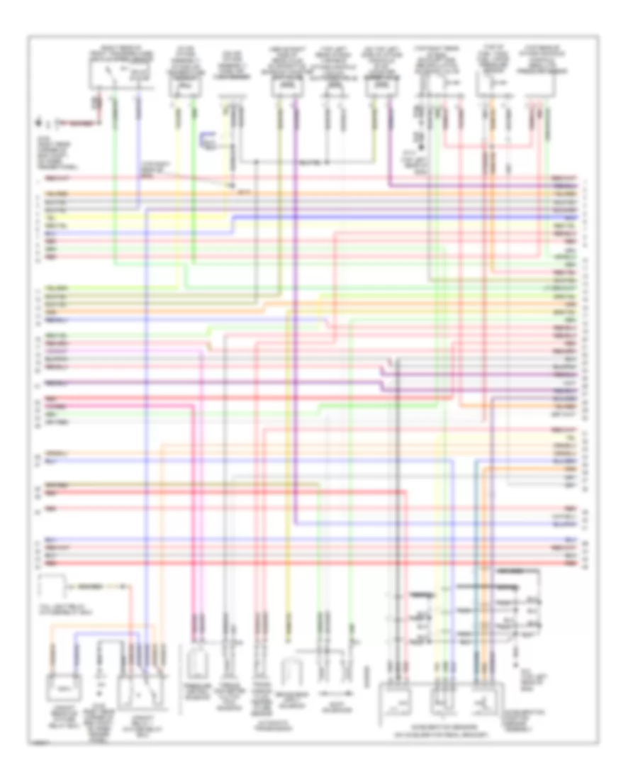
3.5L, Engine Performance Wiring Diagrams (3 of 4) for Isuzu Trooper Limited 2000
List of elements for 3.5L, Engine Performance Wiring Diagrams (3 of 4) for Isuzu Trooper Limited 2000:
- (above right side of rear axle) evaporative emission canister cut valve
- (in air intake assembly) intake air temperature sensor
- (on accelerator pedal bracket)
- (on air intake assembly) mass air- flow sensor
- (on top left side of intake manifold) evap canister purge valve
- (right rear of front transfer case) vehicle speed sensor
- (top left rear of eng)
- (top left rear of eng) variable intake manifold vacuum switching valve
- (top of fuel tank) fuel vapor pressure sensor
- (top rear of intake manifold) manifold absolute pressure sensor
- (top right rear of eng)
- (top right rear of eng) exhaust gas recirculation solenoid valve
- Acceleration position sensor assembly
- Acceleration sensors
- Automatic transmission
- Braided
- G105 (right rear corner of eng compt, on inner fender panel)
- G114
- G117
- G14 (top left rear of eng)
- Gyr/red
- M-6
- M-7
- Nca
- Pressure control solenoid
- Red
- Shift solenoids
- Solid state
- Tail light relay (in fuse/relay box)
- Torque converter clutch pwm solenoid
- Trans- mission fluid temper- ature sensor
- Upshift relay 1 (in fuse relay box)
- Upshift resistor (in fuse/ relay box)
3.5L, Engine Performance Wiring Diagrams (4 of 4) for Isuzu Trooper Limited 2000
List of elements for 3.5L, Engine Performance Wiring Diagrams (4 of 4) for Isuzu Trooper Limited 2000:
- "r/l" range
- "u/s" ind
- (below center console)
- (on top of fuel tank) fuel tank unit
- (others) (s model)
- (top left rear of eng)
- A/t oil temp
- A/t oil temp warning light
- Antilock brakes system
- Ap sensor 1
- Ap sensor 2
- Ap sensor 3
- Aps3 gnd
- Braided
- Braided wires
- Can cut val
- Cancel
- Check trans ind
- Cruise control system
- Cruise lmp
- Cruise sw
- Defog rly
- Defogger system
- Dlc
- Egr ctrl lo
- Egr in
- Engine or powertrain control module (on right side of eng compt)
- Evap purge
- Fuel gage
- Fuel sen
- Fuel sender
- Fuel tank sender
- G114
- G117 (top right rear of eng)
- G302
- Gauge assembly
- Gnd
- Heated oxygen sensor (b1s1) (right exhaust down pipe)
- Heated oxygen sensor (b1s2) (rear of right cat convert)
- Heated oxygen sensor (b2s1) (left exhaust down pipe)
- Heated oxygen sensor (b2s2) (rear of left cat convert)
- Ho2s b1s1 +
- Ho2s b1s1 -
- Ho2s b1s2 +
- Ho2s b1s2 -
- Ho2s b2s1 +
- Ho2s b2s1 -
- Ho2s b2s2 +
- Ho2s b2s2 -
- Ho2s1 h gnd
- Ho2s1h gnd
- I-10
- I-9
- Iat sen
- Ig coil1 ctrl
- Ig coil4 ctrl
- Ig coil5 ctrl
- Ig coil6 ctrl
- Ign feed
- Instrument cluster (vss in)
- Instrument cluster system (fuel gauge)
- Interior lights system
- Malfunc- tion indicator light (mil)
- Map
- Mil ind ctrl
- No6 fuel inj
- Pnk
- Power
- Power/ winter switch (a/t)
- Pwr sw
- Red
- Ref volt
- S10
- S11
- S12
- S13
- S14
- S15
- S16
- S17
- S18
- S19
- S20
- S21
- S22
- S23
- S24
- S25
- S26
- S27
- S28
- S29
- S30
- S31
- S32
- S33
- S34
- S35
- S36
- S37
- S38
- S39
- S40
- S41
- S42
- S43
- S44
- S45
- S46
- S47
- S48
- S49
- S50
- S51
- S52
- S53
- S54
- S55
- S56
- S57
- S58
- S59
- S60
- S61
- S62
- S63
- S64
- S65
- S66
- S67
- S68
- S69
- S70
- S71
- S72
- S73
- S74
- S75
- S76
- S77
- S78
- S79
- S80
- Shift hi
- Tcc sol
- Tft sen
- Tft sen gnd
- Th val mtr
- Tps 1 sign
- Tr 1-2, 3-4
- Tr sign 2-3
- Trans spd
- Transmission speed sensor (a/t) (top of transmission)
- Up s ind ctrl
- Vapor press
- Vim vsv ctrl
- Vss in
- Winter
- Winter drive ind
- Winter lmp
- Winter sw
EXTERIOR LIGHTS
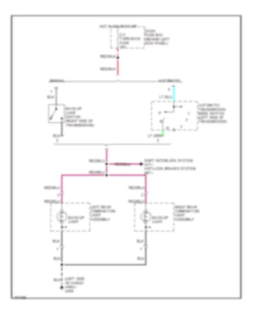
Back-up Lamps Wiring Diagram for Isuzu Trooper Limited 2000
List of elements for Back-up Lamps Wiring Diagram for Isuzu Trooper Limited 2000:
- (left side of cargo area) g400
- Automatic
- Automatic transmission mode switch (left side of transmission)
- Back-up light
- Back-up light switch (right side of transmission)
- C-3 turn back fuse 15a
- Dash fuse box (behind left kick panel)
- Hot in on or start
- Left rear combination light assembly
- Manual
- Right rear combination light assembly
- Shift interlock system (a/t) anti-lock brakes system (m/t)
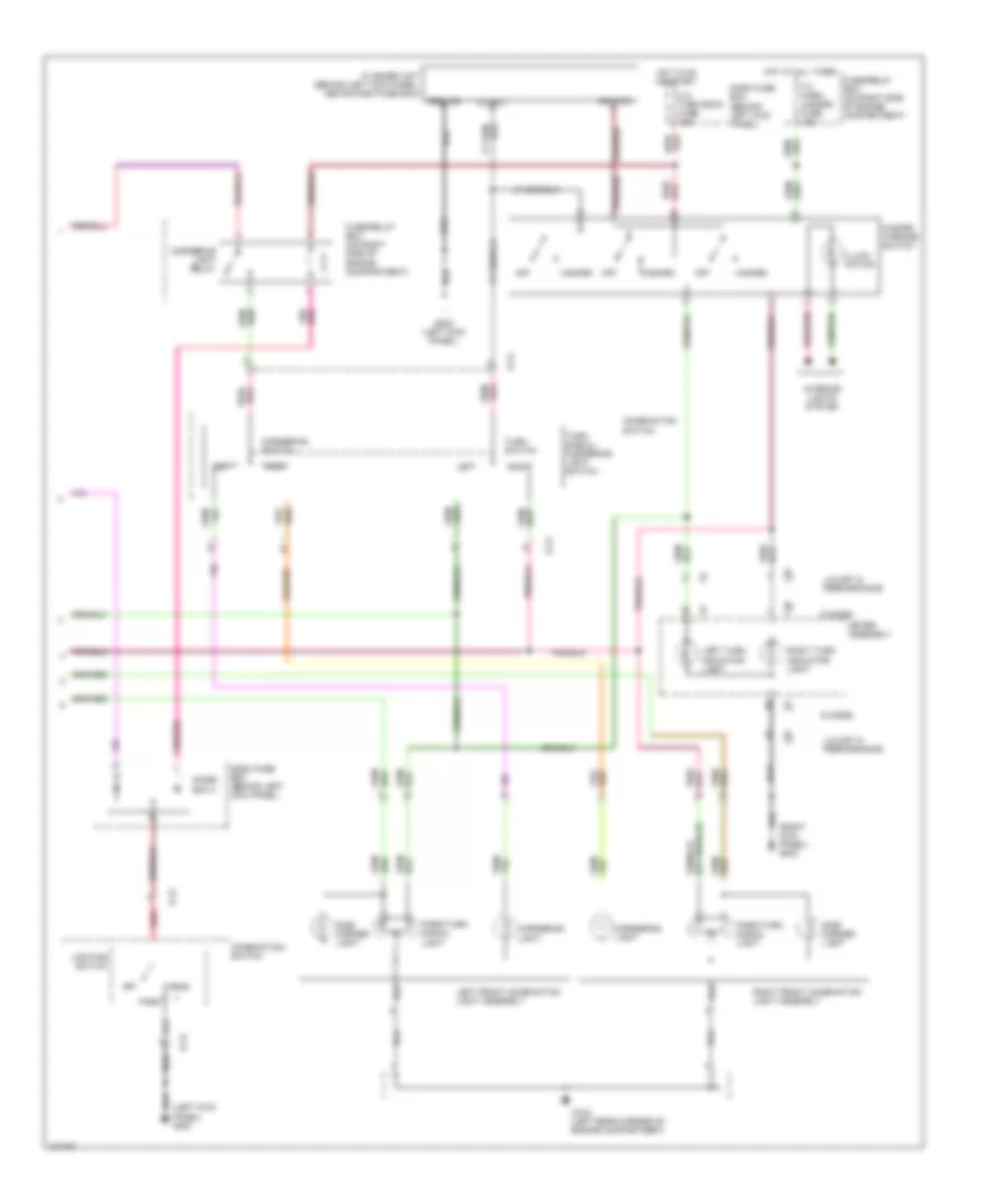
Exterior Lamps Wiring Diagram (1 of 2) for Isuzu Trooper Limited 2000
List of elements for Exterior Lamps Wiring Diagram (1 of 2) for Isuzu Trooper Limited 2000:
- (left kick panel) g200
- (left side of carg0 area) g400
- B-12
- Brake switch (closed w/brake pedal depressed) (behind dash, on brake pedal support)
- Brake/ taillight
- C-14 stoplight a/t cont fuse 15a
- Combination switch
- Dash fuse box (behind left kick panel)
- F-12 tail fuse 15a
- F-4 h/lamp-lh fuse 15a
- Fl-1 main 80a
- Fuse/relay box (on right side of engine compartment)
- G400 (left side of cargo area)
- Head
- High mount stop light
- Hot at all times
- Left rear combination light assembly
- License plate light
- Lighting relay
- Nca
- Off
- Park
- Right rear combination light assembly
- Taillight relay
- Trailer lighting connector (on left rear underside of vehicle, behind rubber grommet)
- Turn signal light
Exterior Lamps Wiring Diagram (2 of 2) for Isuzu Trooper Limited 2000
List of elements for Exterior Lamps Wiring Diagram (2 of 2) for Isuzu Trooper Limited 2000:
- (left kick panel) g200
- (right kick panel) g203
- B-12
- C-3 turn back fuse 15a
- Combination switch
- Cornering light
- Cornering light relay
- Cornering switch
- Dash fuse box (behind left kick panel)
- Diode box 4
- F-3 horn hazard fuse 15a
- Flasher unit (behind left kick panel, above dash fuse box)
- Fuse/relay box (on right side of engine compartment)
- G104 (left rear corner of engine compartment)
- G200 (left kick panel)
- Ground
- Hazard
- Hazard warning switch
- Head
- Hot at all times
- Hot in on or start
- I-10
- I-9
- Ignition
- Illumi- nation
- Interior lights system
- Left
- Left front combination light assembly
- Left turn indicator light
- Lighting switch
- Luxury & performance
- Meter assembly
- Off
- Output
- Park
- Park/turn signal light
- Red
- Right
- Right front combination light assembly
- Right turn indicator light
- S model
- Side marker light
- Turn signal/ cornering light switch
- Turn switch
GROUND DISTRIBUTION
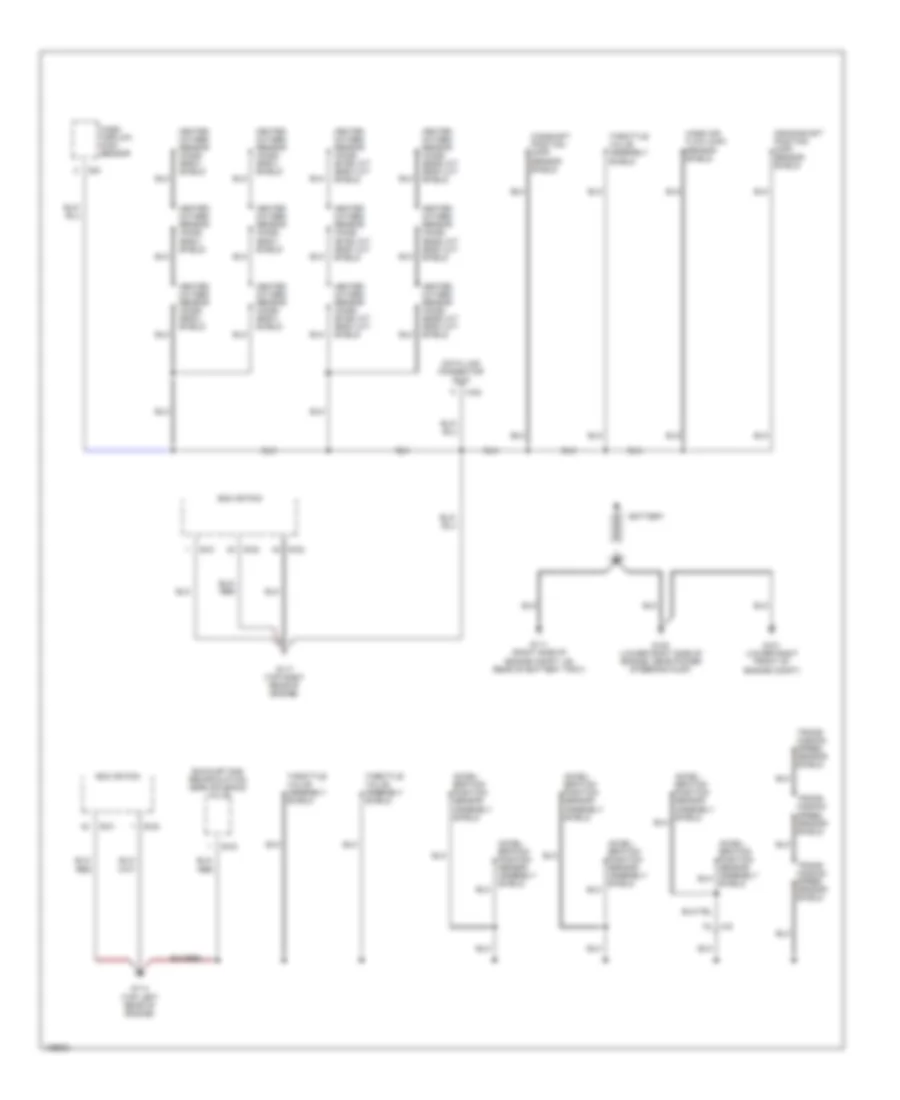
Ground Distribution Wiring Diagram (1 of 4) for Isuzu Trooper Limited 2000
List of elements for Ground Distribution Wiring Diagram (1 of 4) for Isuzu Trooper Limited 2000:
- Accel- eration position sensor assembly shield
- Battery
- C-63
- Camshaft position (cmp) sensor shield
- Crankshaft position (ckp) sensor shield
- Data link connector (dlc)
- E-21
- E-22
- E-33
- E-6
- Ecm or pcm
- Exhaust gas recirculation (egr) solenoid valve
- G101 (lower right front of engine compt)
- G111 (right side of engine compt, on rear of battery tray)
- G114 (top left rear of engine)
- G117 (top right rear of engine)
- G120 (lower right side of engine, near power steering pump)
- H-6
- Heated oxygen sensor (ho2s) (b1s2) a/t (b2s1) m/t shield
- Heated oxygen sensor (ho2s) (b2s1) shield
- Heated oxygen sensor (ho2s) (b2s2) a/t (b2s1) m/t shield
- Mass air flow (maf) sensor shield
- Mass airflow (maf) sensor
- Shield
- Throttle valve assembly shield
- Trans- mission speed sensor shield
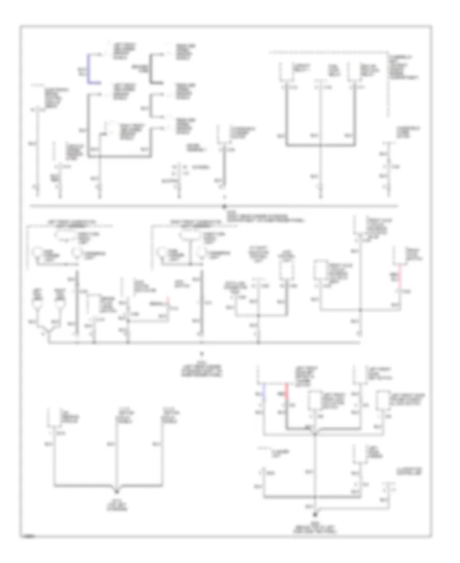
Ground Distribution Wiring Diagram (2 of 4) for Isuzu Trooper Limited 2000
List of elements for Ground Distribution Wiring Diagram (2 of 4) for Isuzu Trooper Limited 2000:
- (s model)
- 1, 3, 5 ignition coils shield
- 2, 4, 6 ignition coils shield
- 4wd control unit
- 4wd motor actuator
- 4wd switch
- A/t shift indicator control unit
- B-53
- Braided wire
- Brake fluid level switch
- C-15
- C-22
- C-31
- C-35
- C-38
- C-4
- C-63
- C-93
- C-94
- Cornering light
- D-3
- D-5
- D-6
- D-8
- D-9
- Data link connector (dlc)
- E-16
- Ecm or pcm main relay
- Electronic brake control module (ebcm)
- Flasher unit
- Front axle switch
- Front axle vacuum solenoid valve (c)- gray
- Fuel pump relay
- Fuse/relay box (on right side of engine compartment)
- G104 (left rear corner of engine compt, on inner fender panel)
- G105 (right rear corner of engine compartment, on inner fender panel)
- G112 (top left of engine)
- G200 (behind top of left dash side trim panel)
- I-10
- I-7
- I-9
- Illumination controller
- Ion sensing module
- Left door mirror
- Left fog- light
- Left front abs speed sensor shield
- Left front combination light assembly
- Left front door key detect & tamper switch
- Left front door key switch
- Left front door lock actuator/ switch
- Left front door power window & lock switch
- M-10
- M-12
- M-22
- M-23
- M-24
- M-26
- Meter assembly
- Park/turn signal light
- Rear abs speed sensor shield
- Red
- Right fog- light
- Right front abs speed sensor shield
- Right front combination light assembly
- Side marker light
- Upshift relay 1
- Vehicle speed sensor (vss)
- Windshield washer motor
- Windshield wiper motor
- X-11
- X-12
- X-16
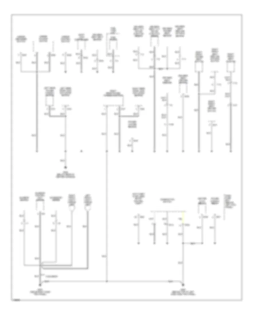
Ground Distribution Wiring Diagram (3 of 4) for Isuzu Trooper Limited 2000
List of elements for Ground Distribution Wiring Diagram (3 of 4) for Isuzu Trooper Limited 2000:
- Accessory meter
- Anti-theft & keyless entry control unit
- B-12
- B-20
- B-24
- B-29
- B-30
- B-31
- B-32
- B-36
- B-37
- B-52
- B-55
- B-56
- B-57
- Combination switch
- D-21
- D-22
- D-26
- D-27
- Dash fuse box (behind left kick panel)
- Driver's power seat switch
- Driver's seat belt switch
- Driver's seat cushion
- Driver's seat heater switch
- Driver's seat recline motor & switch
- Driver's seat tilt motor & switch (front)
- Driver's seat tilt motor & switch (rear)
- F-4
- Fuel pump
- Fuel tank unit
- G200 (behind top of left dash side trim panel)
- G203 (above right dash trim panel)
- G302 (below rear of center console)
- H-46
- H-47
- Heater & a/c relay
- L-1
- L-5
- Left front vanity mirror light
- Left rear door lock actuator/ switch
- Left rear power window switch
- Mirror control switch
- Mirror defogger switch
- Mirror folding switch
- Power window relay
- Power/ winter switch
- Right front power seat switch
- Right front seat cushion
- Right front seat heater switch
- Right front seat recline motor & switch
- Right front vanity mirror light
- Right rear door lock actuator/ switch
- Right rear power window switch
- S-5
- Shift lock controller
- Sunroof control unit motor
- Sunroof switch
- T-10
- T-11
- T-12
- T-3
- T-5
- T-8
- W/sunroof
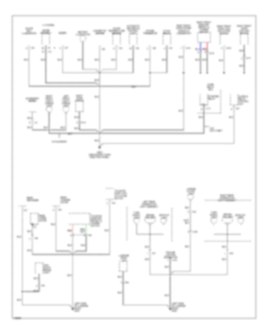
Ground Distribution Wiring Diagram (4 of 4) for Isuzu Trooper Limited 2000
List of elements for Ground Distribution Wiring Diagram (4 of 4) for Isuzu Trooper Limited 2000:
- (left side of luggage room) g400
- Accessory meter
- Alarm & relay control unit
- Ashtray illumination
- Automatic heater-a/c control unit
- B-7
- Back-up light
- Brake/ taillight
- Cigarette lighter
- Clock
- Coil
- D-12
- D-14
- D-16
- D-17
- D-19
- Fuse/ relay box
- G-2
- G-4
- G-5
- G-6
- G-7
- G-8
- G-9
- G203 (above right dash side trim panel)
- Glove box illumination
- H-39
- H-44
- Hi max relay
- High mount brake light
- I-10
- I-22
- I-24
- I-27
- I-32
- I-34
- I-50
- I-51
- I-9
- In-car temperature sensor
- L-5
- Left front vanity mirror light
- Left rear combination light assembly
- License plate light
- Luggage room light
- Meter assembly
- Power transistor
- R-6
- R-7
- R-9
- Rear defogger
- Rear washer motor
- Rear wiper motor
- Red
- Right door mirror
- Right front door key detect & tamper switch
- Right front door lock actuator/ switch
- Right front door lock key switch
- Right front door power window & lock switch
- Right front vanity mirror light
- Right rear combination light assembly
- S model a
- Starter relay
- Tailgate door key detect & tamper switch
- Tailgate door lock actuator/ switch
- Trailer lighting connector
- Turn signal light
- W/o anti-theft
- W/o sunroof
- X-17
HEADLIGHTS
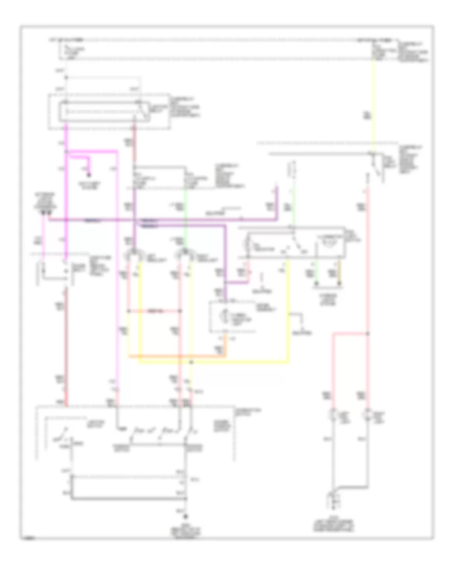
Headlight Wiring Diagram for Isuzu Trooper Limited 2000
List of elements for Headlight Wiring Diagram for Isuzu Trooper Limited 2000:
- Anti-theft system
- B-12
- Combination switch
- Dash fuse box (behind left kick panel)
- Dimmer/ passing switch
- Dimming switch
- Diode box 4
- Exterior lights system (cornering lights)
- F-4 h/lamp-lh fuse 15a
- F-5 h/lamp-rh fuse 15a
- F-8 front fog fuse 15a
- Fl-i main fuse 80a
- Fog light relay
- Fog- light switch
- Fuse/relay box (on right side of engine compart- ment)
- Fuse/relay box (on right side of engine compartment)
- G104 (left rear corner of engine compt, on inner fender panel)
- G200 (behind top of left side dash trim panel)
- Head park
- Hi beam indicator light
- Hot at all times
- I-10
- If equipped
- Illumination
- Interior lights system
- Left fog- light
- Left headlight
- Lighting relay
- Lighting switch
- Meter assembly
- Off
- On indicator
- Passing switch
- Red
- Right fog- light
- Right headlight
HORN
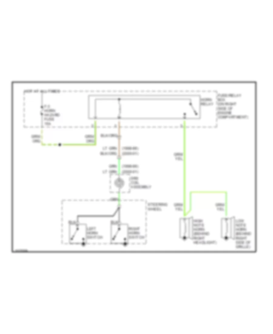
Horn Wiring Diagram for Isuzu Trooper Limited 2000
List of elements for Horn Wiring Diagram for Isuzu Trooper Limited 2000:
- (1998-99)
- (2000-01)
- F-3 horn hazard fuse 15a
- Fuse/relay box (on right side of engine compartment)
- High note horn (behind right headlight)
- Horn relay
- Hot at all times
- Left horn switch
- Low note horn (behind right side of grille)
- Right horn switch
- Srs coil assembly
- Steering wheel
INSTRUMENT CLUSTER
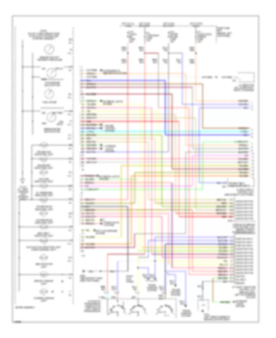
Instrument Cluster Wiring Diagram, Luxury & Performance (1 of 2) for Isuzu Trooper Limited 2000
List of elements for Instrument Cluster Wiring Diagram, Luxury & Performance (1 of 2) for Isuzu Trooper Limited 2000:
- (right kick panel)
- A/t shift indicator control unit (behind dash, left of steering column)
- Abs indicator light
- Alarm & relay control unit (above right kick panel)
- Alternator (on lower right front of engine)
- Anti-lock brakes system
- Automatic transmission mode switch (left side of transmission)
- B-49
- B-6
- Battery
- Brake warning light
- C-3 turn back fuse 15a
- C10 meter gauge fuse 10a
- C11 (audio [acc]) mirror) fuse 10a
- C15 (audio [b]) fuse 20a
- Charge warning light
- Cruise control system
- Cruise main indicator light
- Cruise set indicator light
- Dash fuse box (behind left kick panel)
- Dim input
- Dr seat belt unbuckled input
- Engine coolant temperature gauge
- Exterior lights system
- Fuel gauge
- G104 (left rear corner of engine compartment)
- G203 (above right dash side trim panel)
- Gnd
- Ground
- Headlights system
- Hot at all times
- Hot in acc or on
- Hot in on or start
- I-10
- I-9
- Ign
- Ignition
- Indicator ctrl
- Interior lights system
- Low fuel indicator light
- Malfunction indicator light (check engine light)
- Meter assembly
- Note: do not check resistance of solid state modules in meter assembly
- Oil pressure indicator light
- P-8
- Pnk
- Position input
- Power drive indicator light
- Red
- Rpm in
- Seat belt indicator light
- Speedometer (solid state)
- Tachometer (solid state)
- To a/t oil temp warning light (diagram 2 of 2)
- Torque on demand (tod) control unit (beneath front passenger's seat)
- Trans- missions system
- Vss input
- Winter drive indicator light
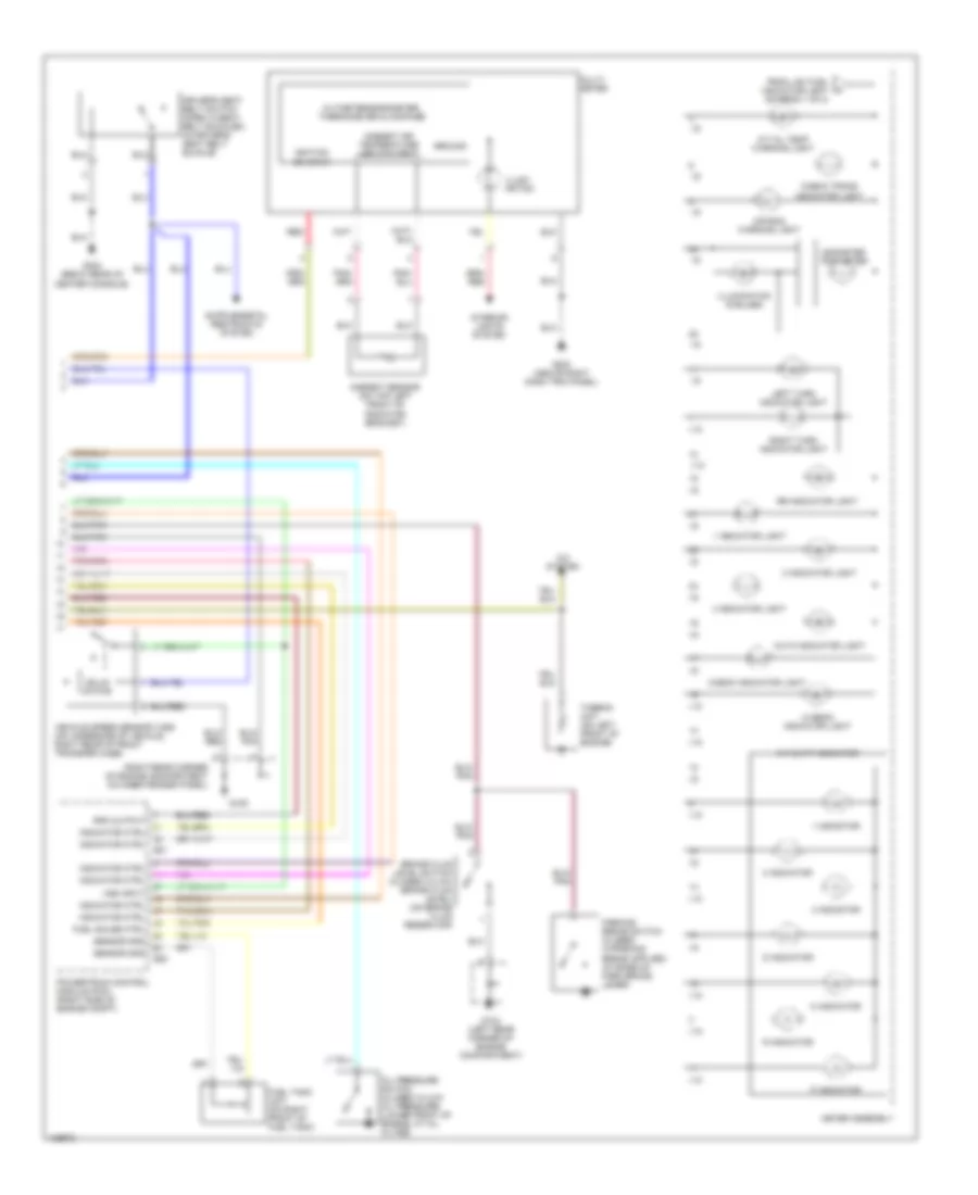
Instrument Cluster Wiring Diagram, Luxury & Performance (2 of 2) for Isuzu Trooper Limited 2000
List of elements for Instrument Cluster Wiring Diagram, Luxury & Performance (2 of 2) for Isuzu Trooper Limited 2000:
- (right rear corner of engine compartment on inner fender panel)
- 1 indicator
- 1 indicator light
- 2 indicator
- 2 indicator light
- 3 indicator
- 3 indicator light
- A/c system
- A/t oil temp warning light
- A/t shift indicator
- Air bag warning light
- Altimeter/barometer, thermometer & compass
- Ambient air temperature input/output
- Ambient sensor (on top left front of radiator bracket)
- Auto indicator light
- Brake fluid level switch (closed w/low brake fluid level) (on brake fluid reservoir)
- Check indicator light
- Check trans indicator light
- D indicator
- Driver's seat belt switch (open w/seat belt buckled) (in driver's seat belt buckle)
- E21
- E22
- From low fuel indicator light (diagram 1 of 2)
- Fuel gauge ctrl
- Fuel tank unit (on right front of fuel tank)
- G104 (left rear corner of engine compartment)
- G105
- G203 (above right dash trim panel)
- G302 (beow rear of center console)
- Ground
- Hi beam indicator light
- I-10
- I-9
- Ignition on input
- Illumi- nation
- Illumination (6 bulbs)
- Indicator ctrl
- Interior lights system
- Left turn indicator light
- Meter assembly
- Multi- meter
- N indicator
- Odometer trip meter
- Oil pressure switch (closed w/low oil pressure) (lower front of engine, at oil filter)
- P indicator
- Powertrain control module (pcm) (right side of engine compt)
- R indicator
- Red
- Right turn indicator light
- Rpm output
- Rr indicator light
- Sensor gnd
- Solid state
- Thermo unit (on left front of engine)
- Vehicle speed sensor (vss) (on underside of vehicle, right rear of front transfer case)
- Vss input
Instrument Cluster Wiring Diagram, S Model (1 of 2) for Isuzu Trooper Limited 2000
List of elements for Instrument Cluster Wiring Diagram, S Model (1 of 2) for Isuzu Trooper Limited 2000:
- 4wd control unit (behind front console)
- 4wd indicator light
- A/t shift indicator control unit (behind dash, left of steering column)
- Abs indicator light
- Alarm & relay control unit (above right kick panel)
- Alternator (on lower right front of engine)
- Automatic transmission mode switch (left side of transmission)
- B-6
- Battery
- Brake warning light
- C-3 turn back fuse 15a
- C-4
- C10 meter gauge fuse 10a
- C11 (audio [acc]) mirror) fuse 10a
- C15 (audio (b)) fuse 20a
- Charge warning light
- Cruise control system
- Cruise main indicator light
- Cruise set indicator light
- Dash fuse box (behind left kick panel)
- Dim input
- Dr seat belt unbuckled input
- Electronic brake control module (ebcm) (right front of engine compartment)
- Engine controls system
- Engine coolant temperature gauge
- Exterior lights system
- Fuel gauge
- G104 (left rear corner of engine compartment)
- G203 (above right dash side trim panel)
- Gnd
- Ground
- Head- lights system
- Hot at all times
- Hot in acc or on
- Hot in on or start
- I-10
- I-9
- Ign
- Ignition
- Indicator ctrl
- Interior lights system
- Low fuel indicator light
- Malfunction indicator light (check engine light)
- Meter assembly
- Note: do not check resistance of solid state modules in meter assembly
- Oil pressure gauge
- Oil pressure indicator light
- P-8
- Pnk
- Position input
- Power drive indicator light
- Rpm in
- Seat belt indicator light
- Speedometer (solid state)
- Srs unit (behind front console)
- Tachometer (solid state)
- To a/t oil temp warning light (diagram 2 of 2)
- Voltmeter
- Vss input
- Winter drive indicator light
Instrument Cluster Wiring Diagram, S Model (2 of 2) for Isuzu Trooper Limited 2000
List of elements for Instrument Cluster Wiring Diagram, S Model (2 of 2) for Isuzu Trooper Limited 2000:
- (left rear corner of engine compartment)
- 1 indicator
- 2 indicator
- 3 indicator
- A/c system
- A/t oil temp warning light
- A/t shift indicator
- Air bag warning light
- Altimeter/barometer, thermometer & compass
- Ambient air temperature input/output
- Ambient sensor (on top left front of radiator bracket)
- Brake fluid level switch (closed w/low brake fluid level) (on brake fluid reservoir)
- Check trans indicator light
- D indicator
- Driver's seat belt switch (open w/seat belt buckled) (in driver's seat belt buckle)
- E21
- E22
- Engine control module (ecm) (or) powertrain control module (pcm) (right side of engine compt)
- From low fuel indicator light (diagram 1 of 2)
- Fuel gauge ctrl
- Fuel tank unit (on right front of fuel tank)
- G104
- G105 (right rear corner of engine compartment)
- G203 (above right dash trim panel)
- G302 (below rear of center console)
- Ground
- Hi beam indicator light
- I-10
- I-9
- Ignition on input
- Illumi- nation
- Illumination (6 bulbs)
- Indicator ctrl
- Interior lights system
- Left turn indicator light
- Meter assembly
- Multi- meter
- N indicator
- Odometer trip meter
- Oil pressure sender unit (lower front of engine, at oil filter)
- Oil pressure switch (closed w/low oil pressure) (lower front of engine, at oil filter)
- P indicator
- R indicator
- Red
- Right turn indicator light
- Rpm output
- Sensor gnd
- Sensor ground
- Solid state
- Thermo unit (on left front of engine)
- Trans posit input
- Upshift indicator light (m/t)
- Vehicle speed sensor (vss) (on underside of vehicle, right rear of front transfer case)
- Vss input
INTERIOR LIGHTS
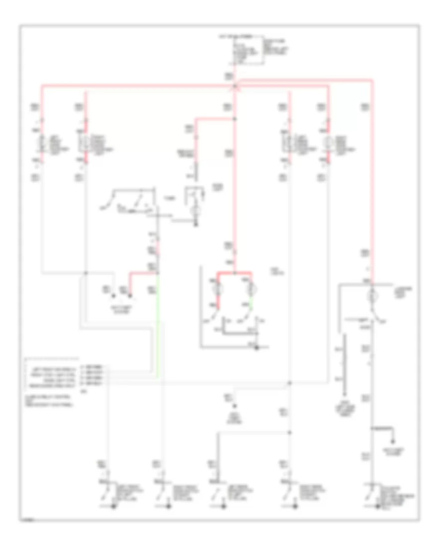
Courtesy Lamps Wiring Diagram, Luxury & Performance for Isuzu Trooper Limited 2000
List of elements for Courtesy Lamps Wiring Diagram, Luxury & Performance for Isuzu Trooper Limited 2000:
- Alarm & relay control unit (above right kick panel)
- Anti- theft system
- Anti-theft system
- B-6
- C-16 clock [b] dome light fuse 10a
- Dash fuse box (behind left kick panel)
- Dome light
- Dome light ctrl
- Door
- Front ctsy light ctrl
- G400 (left side of cargo area)
- Hot at all times
- Left front door courtesy light
- Left front door switch (in left "b" pillar)
- Left front dr open in
- Left rear door courtesy light
- Left rear door switch (in left "c" pillar)
- Luggage room light
- Map lights
- Off
- Rear doors open input
- Red
- Right front door courtesy light
- Right front door switch (in right "b" pillar)
- Right rear door courtesy light
- Right rear door switch (in right "c" pillar)
- Tailgate switch (on center rear of luggage room door sill)
- Timer
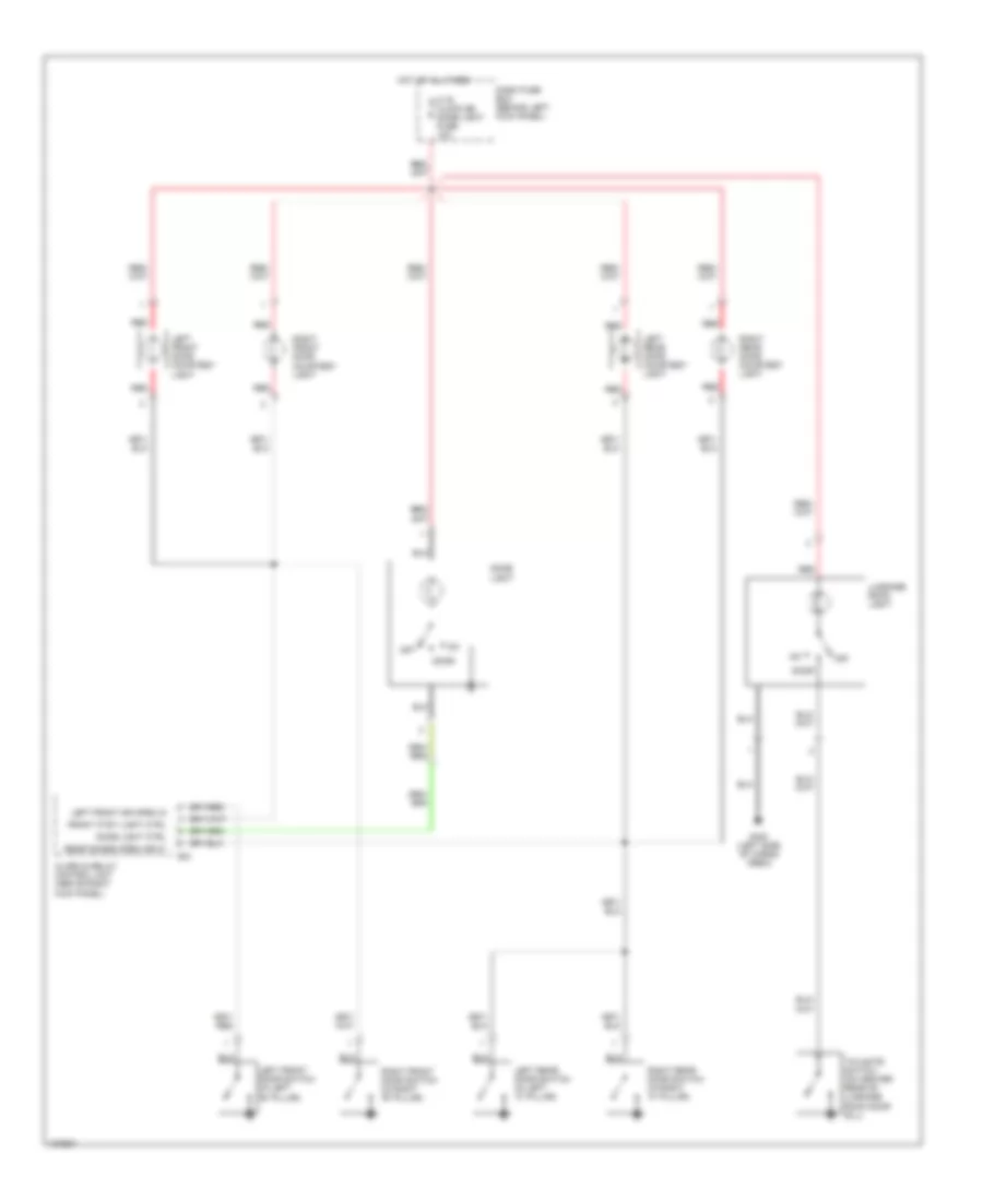
Courtesy Lamps Wiring Diagram, S Model for Isuzu Trooper Limited 2000
List of elements for Courtesy Lamps Wiring Diagram, S Model for Isuzu Trooper Limited 2000:
- Alarm & relay control unit (above right kick panel)
- B-6
- C-16 clock [b] dome light fuse 10a
- Dash fuse box (behind left kick panel)
- Dome light
- Dome light ctrl
- Door
- Front ctsy light ctrl
- G400 (left side of cargo area)
- Hot at all times
- Left front door courtesy light
- Left front door switch (in left "b" pillar)
- Left front dr open in
- Left rear door courtesy light
- Left rear door switch (in left "c" pillar)
- Luggage room light
- Off
- Rear doors open input
- Red
- Right front door courtesy light
- Right front door switch (in right "b" pillar)
- Right rear door courtesy light
- Right rear door switch (in right "c" pillar)
- Tailgate switch (on center rear of luggage room door sill)
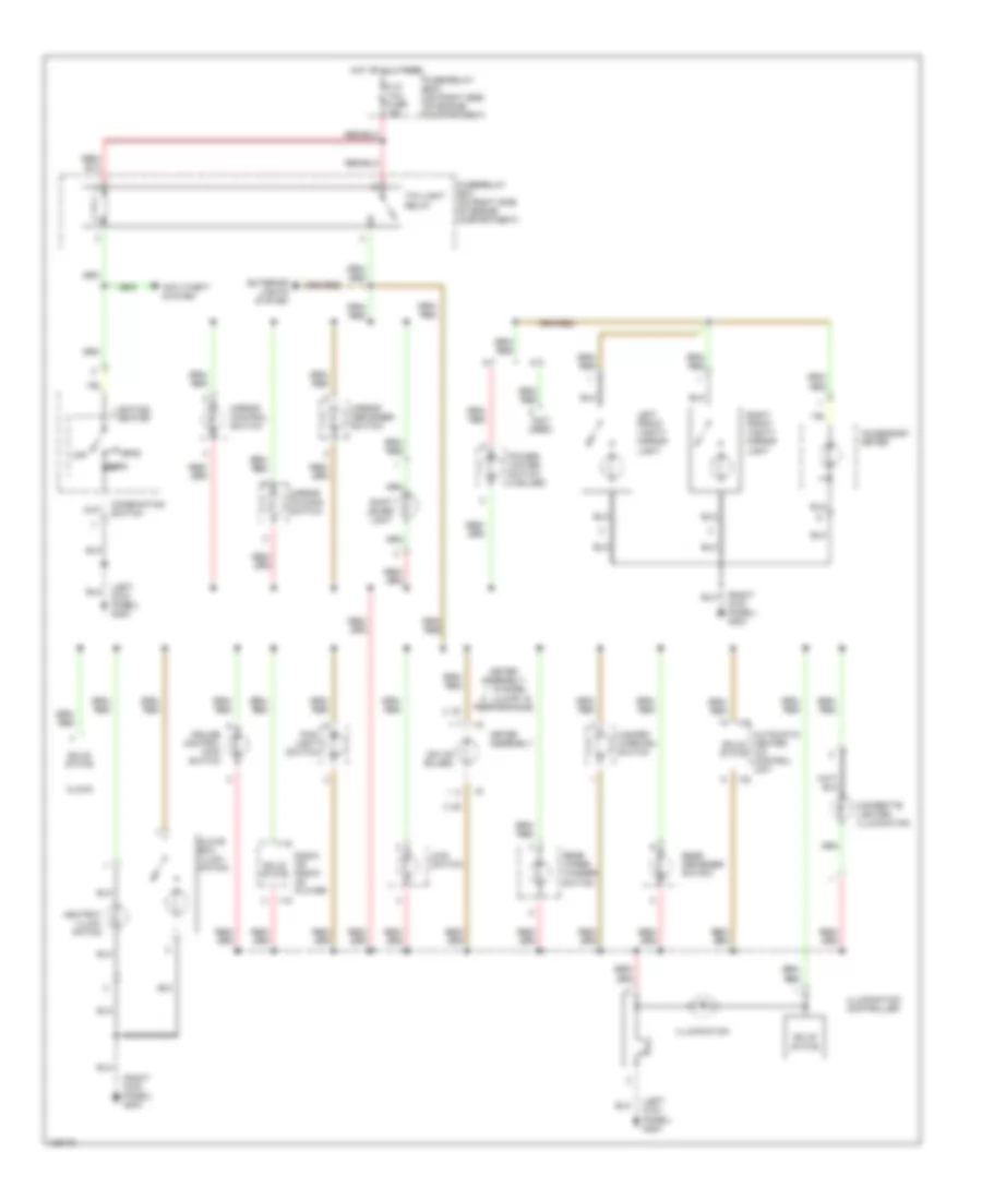
Instrument Illumination Wiring Diagram for Isuzu Trooper Limited 2000
List of elements for Instrument Illumination Wiring Diagram for Isuzu Trooper Limited 2000:
- (left kick panel) g200
- (not used)
- (right kick panel) g203
- (six (6) bulbs)
- 4wd switch
- A/t
- Accessory meter
- Anti-theft system
- Ashtray illumi- nation
- Automatic heater a/c control unit
- Cigarette lighter illumination
- Clock
- Combination switch
- Cruise control main switch
- Exterior lights system
- F-12 tail fuse 15a
- Fog- light switch
- Fuse/relay box (on right side of engine compartment)
- Glove box illumi- nation
- Hazard warning switch
- Head
- Hot at all times
- I-15
- I-32
- I-9
- Illumination
- Illumination controller
- Left front vanity mirror light
- Lighting switch
- M/t
- Meter assembly
- Meter assembly:
- Mirror control switch
- Mirror defogger switch
- Mirror folding switch
- Off
- Park
- Performance
- Power/ winter switch (2 bulbs)
- Radio or radio/ cd player
- Rear defogger switch
- Rear wiper/ washer switch
- Right front vanity mirror light
- S model luxury &
- Shift lever light
- Solid state
- Taillight relay
POWER DISTRIBUTION
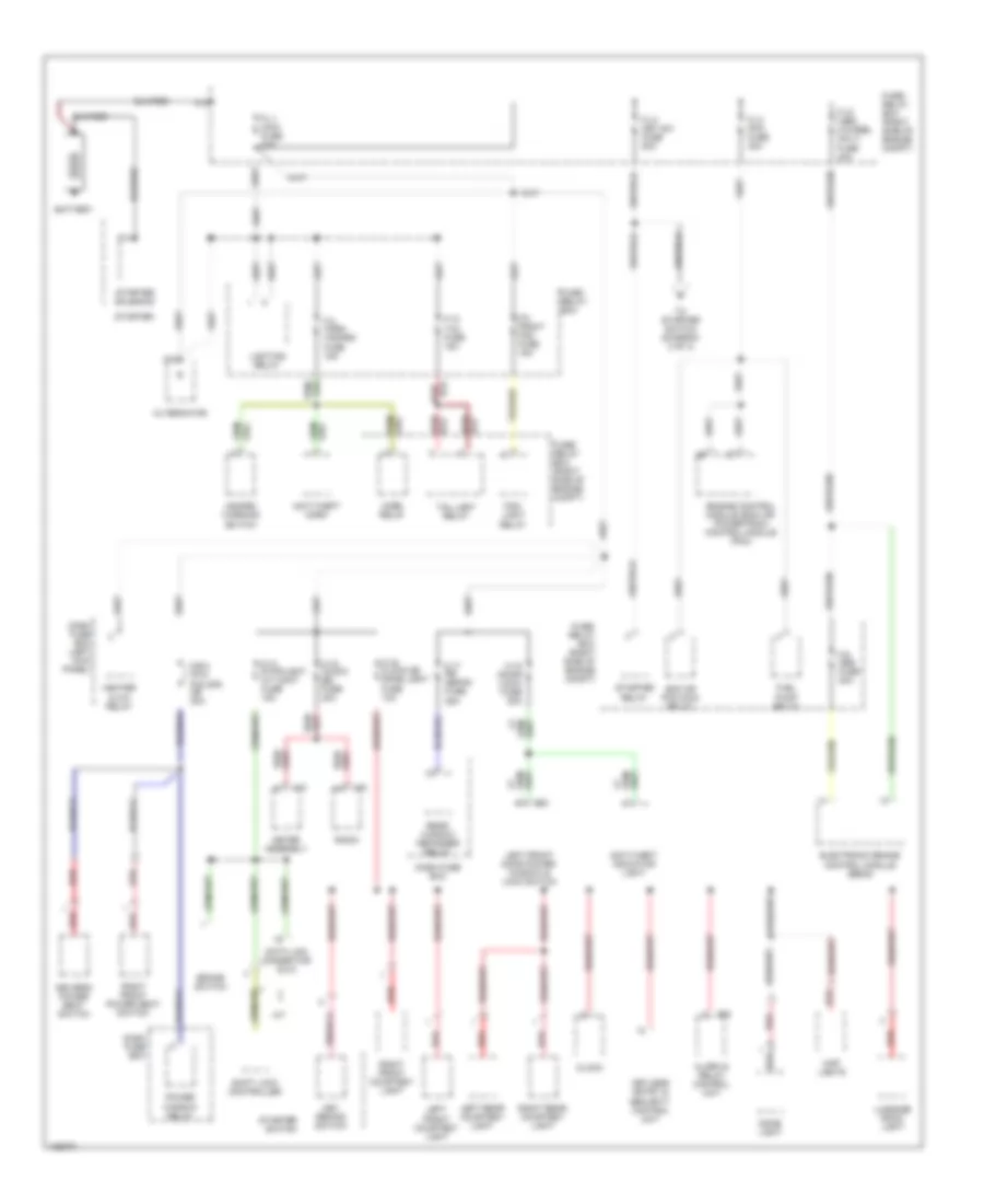
Power Distribution Wiring Diagram (1 of 3) for Isuzu Trooper Limited 2000
List of elements for Power Distribution Wiring Diagram (1 of 3) for Isuzu Trooper Limited 2000:
- A/t
- Alarm & relay control unit
- Alternator
- Anti-theft horn
- Anti-theft indicator light
- B-6
- Battery
- Brake switch
- C-14 stoplight a/t cont fuse 15a
- C-15 (audio [b]) fuse 20a
- C-16 clock [b] dome light fuse 10a
- C-17 rr defog fuse 25a
- C-18 (door lock) fuse 20a
- C/b-2 (p/w, p/s, s/r) cb 30a
- Clock
- D-5
- Dash fuse box
- Dash fuse box (left kick panel)
- Data link connector (dlc)
- Dome light
- Driver's power seat switch
- Ecm or pcm main relay
- Electronic brake control module (ebcm)
- Engine control module (ecm) or powertrain control module (pcm)
- F-12 tail fuse 15a
- F-3 horn hazard fuse 15a
- F-8 front fog fuse 15a
- F-9 abs fuse 20a
- Fl-1 main fuse 80a
- Fl-2 key sw fuse 50a
- Fl-3 pcm fuse 30a
- Fl-6 (abs 4/wheel only) fuse 40a
- Fog- light relay
- Fuel pump relay
- Fuse/ relay box
- Fuse/ relay box (right side of engine compt)
- Hazard warning switch
- Heater & a/c relay
- Horn relay
- I-10
- I-15
- Key remind switch
- Keyless entry & security control unit
- Left front courtesy light
- Left front door power window & lock switch
- Left rear courtesy light
- Lighting relay
- Luggage room light
- Map lights
- Meter assembly
- P-2
- P-4
- P-9
- Power window relay
- Radio
- Rear window defogger relay
- Red
- Red/
- Right front courtesy light
- Right front power seat switch
- Right rear courtesy light
- Shift lock controller
- Starter
- Starter relay
- Starter solenoid
- Starter switch
- Taillight relay
- To starter switch (diagram 2 of 3)
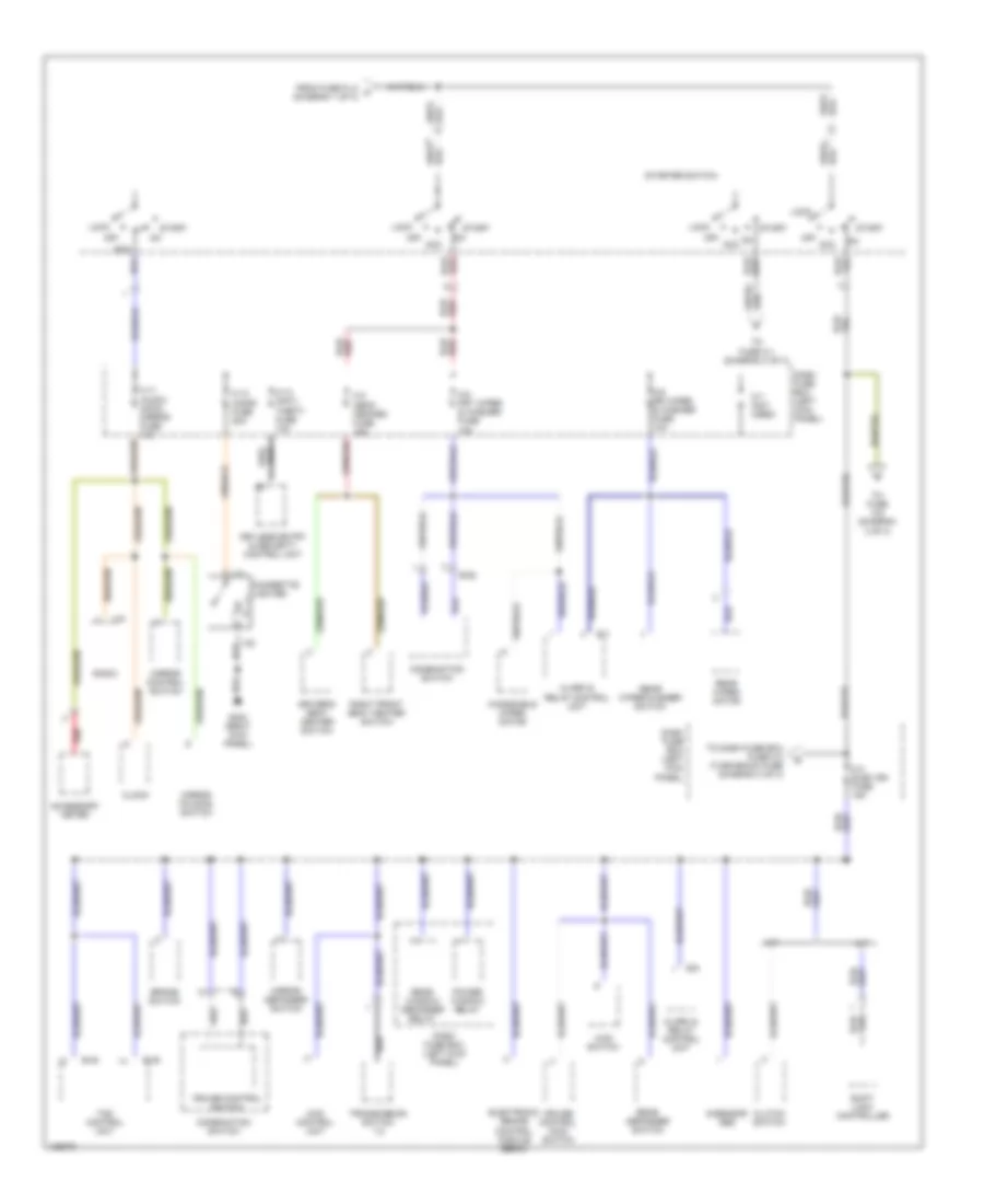
Power Distribution Wiring Diagram (2 of 3) for Isuzu Trooper Limited 2000
List of elements for Power Distribution Wiring Diagram (2 of 3) for Isuzu Trooper Limited 2000:
- 4wd control unit
- 4wd switch
- A/t
- Acc
- Accessory meter
- Alarm & relay control unit
- B-48
- B-49
- B-52
- B-6
- B-7
- Brake switch
- C-11 (audio [acc]) mirror fuse 10a
- C-12 cigar fuse 20a
- C-13 (anti- theft) fuse 10a
- C-2 (seat heater) fuse 15a
- C-4 elec ign fuse 15a
- C-5 frt wiper & washer fuse 15a
- C-6 rr wiper & washer fuse 10a
- C-7 (not used)
- Cigarette lighter
- Clock
- Clutch switch
- Combination switch
- Cruise control main switch
- Cruise control switch
- Dash fuse box (left kick panel)
- Driver's seat heater switch
- Electronic brake control module (ebcm)
- From fuse fl-2 a (diagram 1 of 3)
- G-sensor abs
- G203 (right kick panel)
- I-15
- I-21
- I-22
- Keyless entry & security control unit
- Lock
- M/t
- Mirror control switch
- Mirror defogger switch
- Mirror folding switch
- Off
- Power window relay
- Radio
- Rear defogger switch
- Rear window defogger relay
- Rear wiper motor
- Rear wiper/washer switch
- Red
- Right front seat heater switch
- Shift lock controller
- Start
- Starter switch
- To dash fuse box fuse c-3 (turn-back) fuse (diagram 3 of 3)
- To fuse c-1 (diagram 3 of 3)
- To fuse c-8 (diagram 3 of 3)
- Tod control unit
- Transmission switch 1-2
- Windshield wiper motor
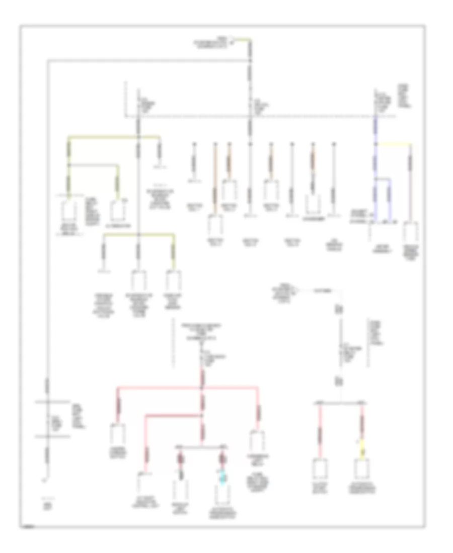
Power Distribution Wiring Diagram (3 of 3) for Isuzu Trooper Limited 2000
List of elements for Power Distribution Wiring Diagram (3 of 3) for Isuzu Trooper Limited 2000:
- (diagram 2 of 3)
- (except s model)
- (s model)
- A/t
- A/t shift indicator control unit
- Alternator
- Automatic transmission mode switch
- Back-up light switch
- C-1 starter relay fuse 10a
- C-10 meter gauge fuse 10a
- C-21 srs-1 fuse 10a
- C-3 turn back fuse 15a
- C-8 engine fuse 15a
- C-9 ign coil fuse 15a
- Clutch start switch
- Condenser
- Cornering light relay
- Dash fuse box (left kick panel)
- Ecm or pcm main relay
- Evaporative emission (evap) canister cut valve
- Evaporative emission (evap) canister purge valve
- From dash fuse box c-4 elec ign fuse (diagram 2 of 3)
- From starter switch b
- From starter switch c
- Fuse/ relay box (right side of engine compt)
- Hazard warning switch
- I-9
- Ignition coil 1
- Ignition coil 2
- Ignition coil 3
- Ignition coil 4
- Ignition coil 5
- Ignition coil 6
- Ion sensing module
- M/t
- Mass air- flow (maf) sensor
- Meter assembly
- P-8
- Srs fuse box (left kick panel)
- Srs unit
- Variable intake manifold vacuum switching valve
- Vehicle speed sensor (vss)
POWER DOOR LOCKS
Power Door Lock Wiring Diagram for Isuzu Trooper Limited 2000
List of elements for Power Door Lock Wiring Diagram for Isuzu Trooper Limited 2000:
- Anti-theft & keyless entry control unit (behind front console)
- C-18 (door lock) fuse 20a
- C-4 elec. ign. fuse 15a
- C/b-2 (p/w, p/s, s/r) cb 30a
- Control unit
- D-30
- D-5
- Dash fuse box (behind left kick panel)
- Door lock switch
- Driver's door power window & lock switch
- G200 (behind top of left dash side trim panel)
- G203 (above right dash side trim panel)
- Hot at all times
- Hot in on or start
- Left front door lock actuator/switch
- Left front door lock key switch
- Left rear door lock actuator/switch
- Lock
- Lock input
- Lock relay
- Power window relay
- Red
- Right front door lock actuator/switch
- Right front door lock key switch
- Right front door power window & lock switch
- Right rear door lock actuator/switch
- Tailgate door lock actuator/switch
- Unlock
- Unlock input
- Unlock output
- Unlock relay
POWER MIRRORS
Power Mirror Wiring Diagram for Isuzu Trooper Limited 2000
List of elements for Power Mirror Wiring Diagram for Isuzu Trooper Limited 2000:
- C-11 (audio [acc]) mirror fuse 10a
- Close
- Dash fuse box (behind left kick panel)
- Defogger system
- Down
- Fold
- Folding motor
- G302 (below center console)
- Hot in on or acc
- Illumination
- Interior lights system
- Left
- Left door mirror
- Left/right motor
- Master selector switch
- Mirror control switch
- Mirror control switch internal switch positions
- Mirror defogger
- Mirror direction selected
- Mirror folding switch
- Open
- Red
- Return
- Right
- Right door mirror
- Switch 1
- Switch 2
- Switch 3
- Switch 4
- Up/down motor
POWER SEATS
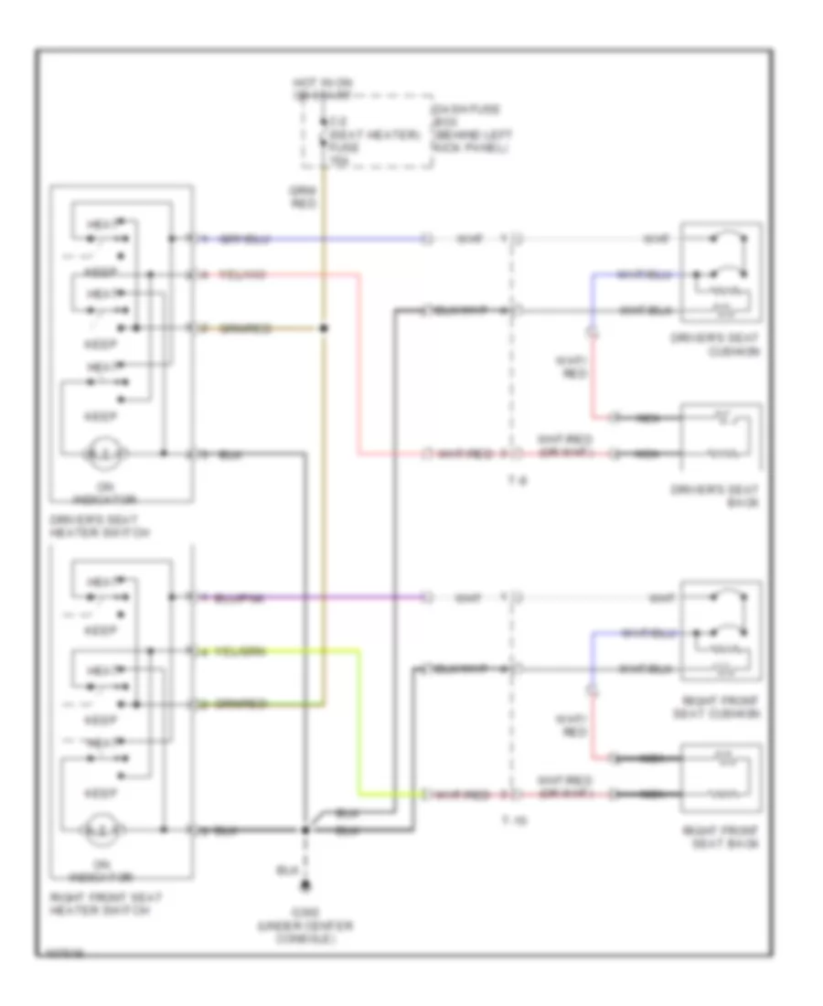
Heated Seats Wiring Diagram for Isuzu Trooper Limited 2000
List of elements for Heated Seats Wiring Diagram for Isuzu Trooper Limited 2000:
- C-2 (seat heater) fuse 15a
- Dash fuse box (behind left kick panel)
- Driver's seat back
- Driver's seat cushion
- Driver's seat heater switch
- G302 (under center console)
- Heat
- Hot in on or start
- Keep
- Nca
- On indicator
- Right front seat back
- Right front seat cushion
- Right front seat heater switch
- T-10
- T-8
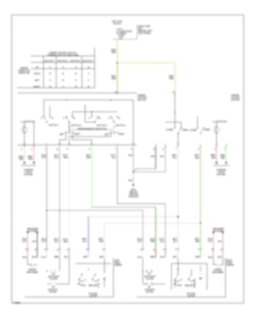
Power Seats Wiring Diagram for Isuzu Trooper Limited 2000
List of elements for Power Seats Wiring Diagram for Isuzu Trooper Limited 2000:
- (below center console) g302
- C/b-2 (p/w, p/s, s/r) cb 30a
- Dash fuse box (behind left kick panel)
- Down
- Driver's power seat switch
- Driver's seat recline motor & switch
- Driver's seat slide motor
- Driver's seat tilt motor & switch (front)
- Driver's seat tilt motor & switch (rear)
- Front
- H-46
- H-47
- Hot at all times
- Nca
- Rear
- Recliner switch
- Red
- Right front power seat switch
- Right front seat recline motor & switch
- Right front seat slide motor
- Slide switch
- T-1
- T-11
- T-12
- T-13
- T-2
- T-3
- T-4
- T-5
- T-6
- T-7
- T-9
- Tilt & slide switch
POWER TOP/SUNROOF
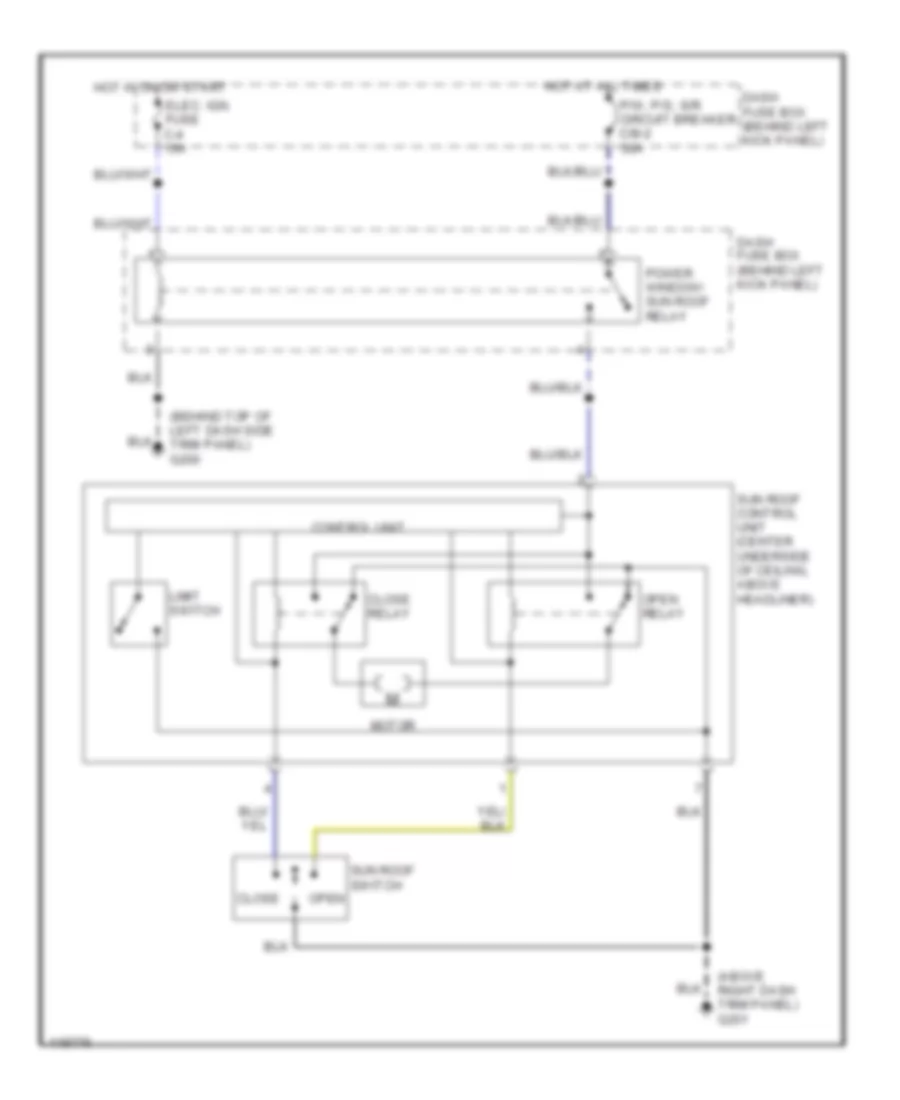
Power Top/Sunroof Wiring Diagrams for Isuzu Trooper Limited 2000
List of elements for Power Top/Sunroof Wiring Diagrams for Isuzu Trooper Limited 2000:
- (above right dash trim panel) g201
- (behind top of left dash side trim panel) g200
- Close
- Close relay
- Control unit
- Dash fuse box (behind left kick panel)
- Elec. ign. fuse c-4 15a
- Hot at all times
- Hot in on or start
- Limit switch
- Motor
- Open relay
- P/w, p/s, s/r circuit breaker c/b-2 30a
- Power window/ sun roof relay
- Sun roof control unit (center underside of ceiling, above headliner)
- Sun roof switch open
POWER WINDOWS
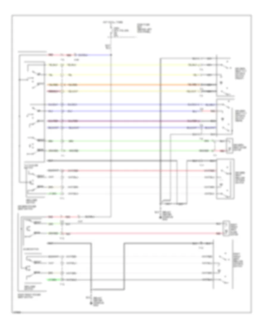
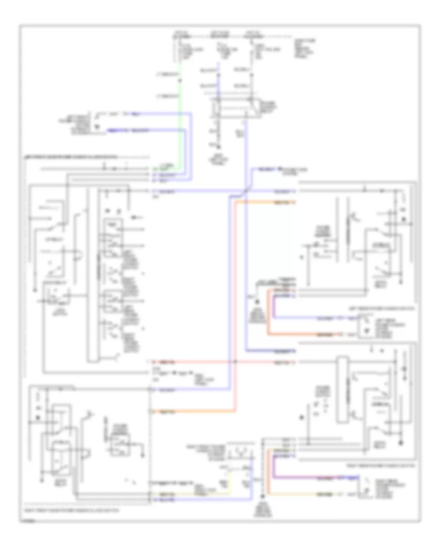
Power Window Wiring Diagram for Isuzu Trooper Limited 2000
List of elements for Power Window Wiring Diagram for Isuzu Trooper Limited 2000:
- Auto
- C-18 door lock fuse 20a
- C-4 elec ign fuse 15a
- C/b-2 (p/w, p/s, s/r) cb 30a
- Control unit
- D-30
- D-5
- Dash fuse box (behind left kick panel)
- Down relay
- G200 (left kick panel)
- G203 (right kick panel)
- G302 (below center console)
- Hot at all times
- Hot in on or start
- Left front door power window & lock switch
- Left front power window motor (in front of door)
- Left front power window switch
- Left rear power window motor (in front of door)
- Left rear power window switch
- Lock switch
- Not used
- Off
- Power tops system
- Power window relay
- Power window switch
- Right front door power window & lock switch
- Right front power window motor (in front of door)
- Right front power window switch
- Right rear power window motor (in front of door)
- Right rear power window switch
- Up relay
RADIO
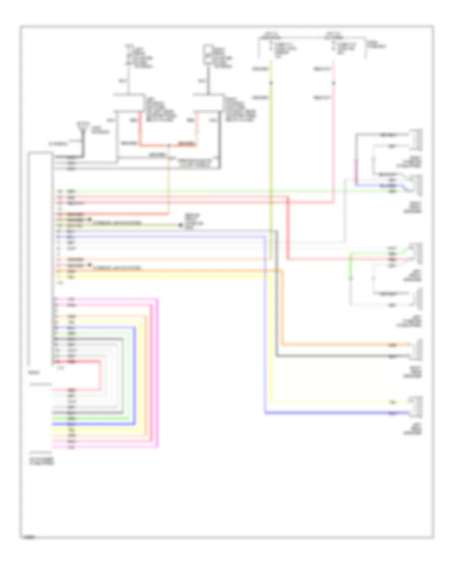
Radio Wiring Diagrams for Isuzu Trooper Limited 2000
List of elements for Radio Wiring Diagrams for Isuzu Trooper Limited 2000:
- (behind front console) g302
- Cd changer (if equipped)
- Dash fuse box
- Fuse c-11 audio (acc) mirror 10a
- Fuse c-15 audio (b) 20a
- Hot at all times
- Hot in acc or on
- I-15
- Interior lights system
- J-10
- Left antenna amplifier (on left rear quarter panel, below glass)
- Left front speaker
- Left rear quarter glass antenna
- Left rear speaker
- Left tweeter (if equipped)
- Mast antenna
- Nca
- Performance or luxury models
- Pnk
- Radio
- Red
- Right antenna amplifier (on right rear quarter panel, below glass)
- Right front speaker
- Right rear quarter glass antenna
- Right rear speaker
- Right tweeter (if equipped)
- S models
SHIFT INTERLOCKS
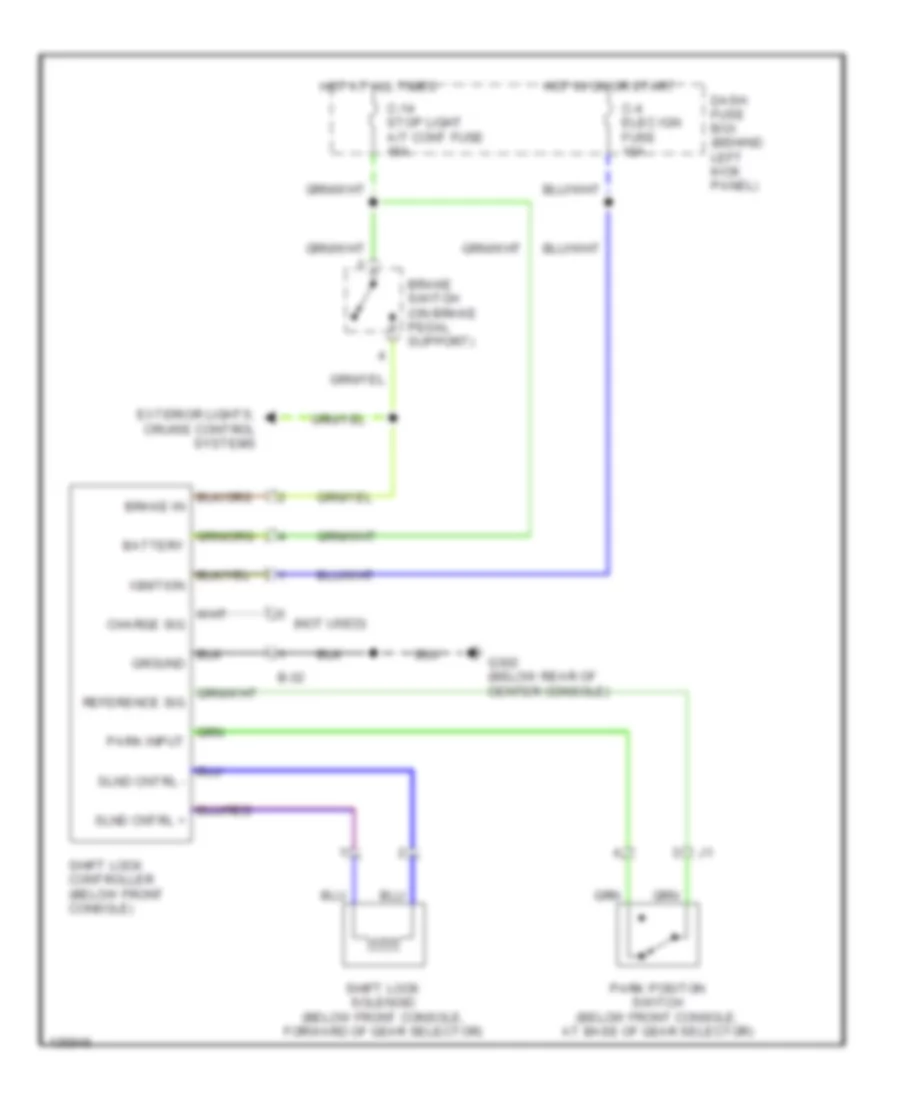
Shift Interlock Wiring Diagram for Isuzu Trooper Limited 2000
List of elements for Shift Interlock Wiring Diagram for Isuzu Trooper Limited 2000:
- (not used)
- B-32
- Battery
- Brake in
- Brake switch (on brake pedal support)
- C-14 stop light a/t cont fuse 15a
- C-4 elec ign fuse 15a
- Charge sig
- Dash fuse box (behind left kick panel)
- Exterior lights, cruise control systems
- G302 (below rear of center console)
- Ground
- Hot at all times
- Hot in on or start
- Ignition
- Park input
- Park positon switch (below front console, at base of gear selector)
- Reference sig
- Shift lock controller (below front console)
- Shift lock solenoid (below front console, forward of gear selector)
- Slnd cntrl +
- Slnd cntrl -
STARTING/CHARGING
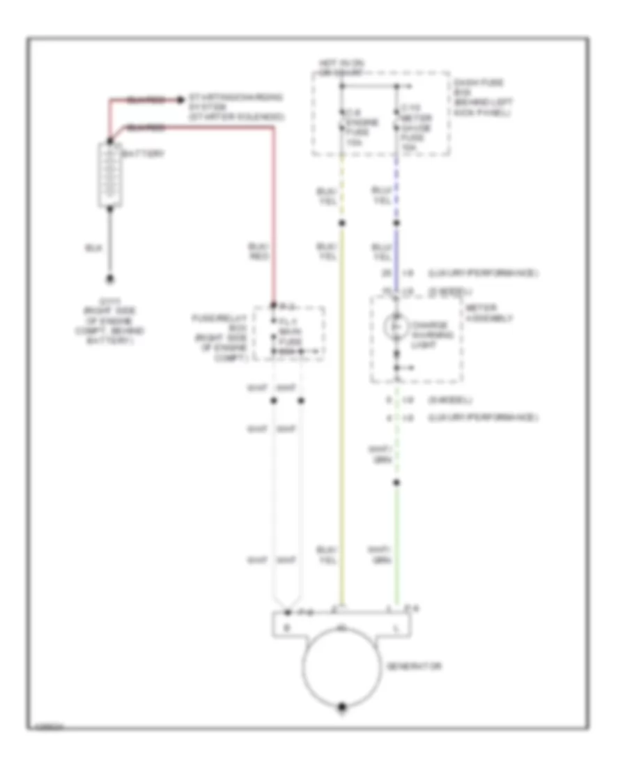
Charging Wiring Diagram for Isuzu Trooper Limited 2000
List of elements for Charging Wiring Diagram for Isuzu Trooper Limited 2000:
- (luxury/performance)
- (s model)
- (s-model)
- Battery
- C-10 meter gauge fuse 10a
- C-8 engine fuse 15a
- Charge warning light
- Dash fuse box (behind left kick panel)
- Fl-1 main fuse 80a
- Fuse/relay box (right side of engine compt)
- G111 (right side of engine compt, behind battery)
- Generator
- Hot in on or start
- I-9
- Meter assembly
- P-2
- P-8
- P-9
- Starting/charging system (starter solenoid)
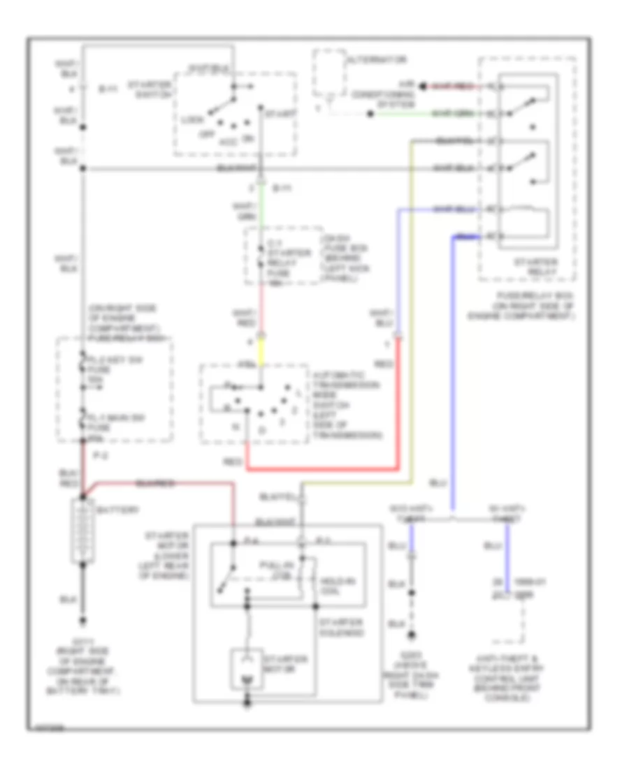
Starting Wiring Diagram, A/T for Isuzu Trooper Limited 2000
List of elements for Starting Wiring Diagram, A/T for Isuzu Trooper Limited 2000:
- (on right side of engine compartment) fuse/relay box
- 1999-01
- Air conditioning system
- Alternator
- Anti-theft & keyless entry control unit (behind front console)
- Automatic transmission mode switch (left side of transmission)
- B-11
- Battery
- C-1 starter relay fuse 10a
- Dash fuse box (behind left kick panel)
- Fl-1 main sw fuse 80a
- Fl-2 key sw fuse 50a
- Fuse/relay box (on right side of engine compartment)
- G111 (right side of engine compartment, on rear of battery tray)
- G203 (above right dash side trim panel)
- Hold-in coil
- Lock
- Off acc
- P-2
- P-3
- P-4
- Pull-in coil
- Red
- Start
- Starter motor
- Starter motor (lower left rear of engine)
- Starter relay
- Starter solenoid
- Starter switch
- W/ anti- theft
- W/o anti- theft
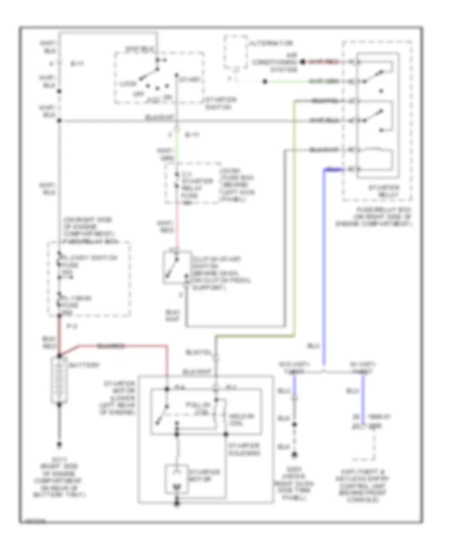
Starting Wiring Diagram, M/T for Isuzu Trooper Limited 2000
List of elements for Starting Wiring Diagram, M/T for Isuzu Trooper Limited 2000:
- (on right side of engine compartment) fuse/relay box
- 1999-01
- Air conditioning system
- Alternator
- Anti-theft & keyless entry control unit (behind front console)
- B-11
- Battery
- C-1 starter relay fuse 10a
- Clutch start switch (behind dash, on clutch pedal support)
- Dash fuse box (behind left kick panel)
- Fl-1 main fuse 80a
- Fl-2 key switch fuse 50a
- Fuse/relay box (on right side of engine compartment)
- G111 (right side of engine compartment, on rear of battery tray)
- G203 (above right dash side trim panel)
- Hold-in coil
- Lock
- Off acc
- P-2
- P-3
- P-4
- Pull-in coil
- Start
- Starter motor
- Starter motor (lower left rear of engine)
- Starter relay
- Starter solenoid
- Starter switch
- W/ anti- theft
- W/o anti- theft
SUPPLEMENTAL RESTRAINTS
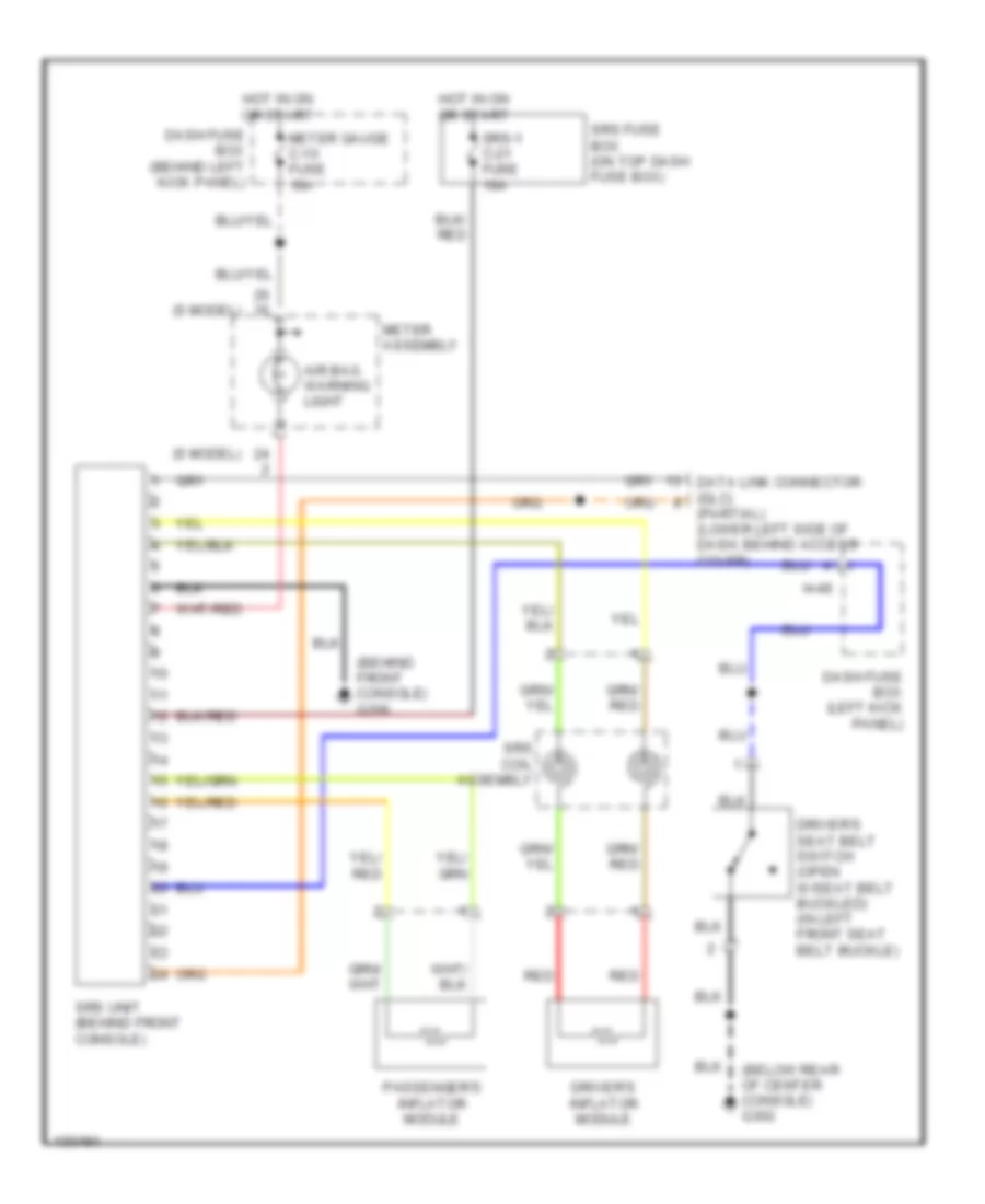
Supplemental Restraint Wiring Diagram for Isuzu Trooper Limited 2000
List of elements for Supplemental Restraint Wiring Diagram for Isuzu Trooper Limited 2000:
- (behind front console) g206
- (below rear of center console) g302
- (partial) (lower left side of dash, behind access cover)
- (s model)
- Air bag warning light
- Dash fuse box (behind left kick panel)
- Dash fuse box (left kick panel)
- Data link connector (dlc)
- Driver's inflator module
- Driver's seat belt switch (open w/seat belt buckled) (in left front seat belt buckle)
- H-49
- Hot in on or start
- Meter assembly
- Meter gauge c-10 fuse 10a
- Passenger's inflator module
- Red
- Srs coil assembly
- Srs fuse box (on top dash fuse box)
- Srs unit (behind front console)
- Srs-1 c-21 fuse 10a
TRANSMISSION
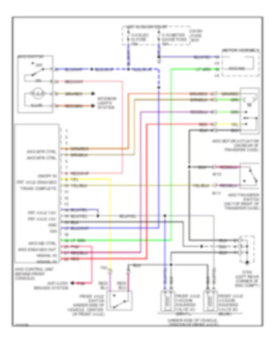
4WD Wiring Diagram, Shift on the Fly for Isuzu Trooper Limited 2000
List of elements for 4WD Wiring Diagram, Shift on the Fly for Isuzu Trooper Limited 2000:
- (under side of vehicle, center of front axle)
- 4wd control unit (behind front console)
- 4wd engaged out
- 4wd ind
- 4wd ind ctrl
- 4wd motor actuator (on rear of transfer case)
- 4wd mtr ctrl
- 4wd switch
- 4wd transfer switch (on top right of transfer case)
- Anti-lock brakes system
- C-10 meter gauge fuse 10a
- C-4 elec ig fuse 15a
- Dash fuse box
- Front axle switch (under side of vehicle, center of front axle)
- Front axle vacuum solenoid valve (c) (gray)
- Frt axle engaged
- Frt axle vsv
- G104 (left rear corner of eng compt)
- Gnd
- High/4l in
- Hot in on or start
- I-9
- Ign
- Illum
- Interior lights system
- M-11
- M-12
- Meter assembly
- Off
- On/off in
- Pnk
- Red
- Trans complete
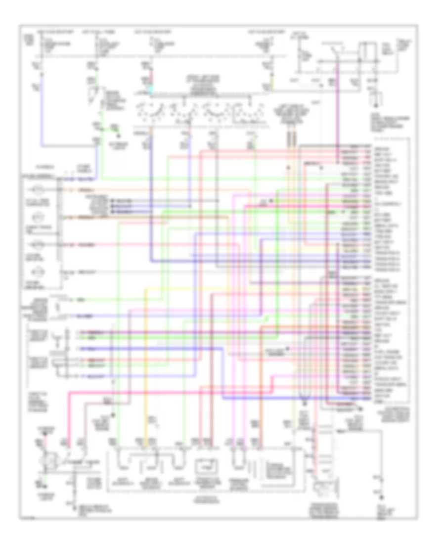
4WD Wiring Diagram, Torque on Demand for Isuzu Trooper Limited 2000
List of elements for 4WD Wiring Diagram, Torque on Demand for Isuzu Trooper Limited 2000:
- (11)
- (12)
- (13)
- (14)
- (15)
- (16)
- (17)
- (18)
- (19)
- (20)
- (22)
- (23)
- (29)
- (30)
- (31)
- (32)
- (33)
- (34)
- (36)
- (37)
- (4)
- (42)
- (44)
- (45)
- (46)
- (47)
- (6)
- (8)
- (except s models)
- (left side of dash, above engine hood release lever) data link connector
- (not used)
- (on lower rear of transfer case) transfer rear speed sensor
- (s models)
- (top of transfer case, on shift lever bracket)
- (top right corner of eng) g117
- 1 ind
- 2 ind
- 3 ind
- 4 h/l transfer switch assembly (bottom front of transfer case)
- 4h switch
- 4l switch
- 4wd engage out
- 4wd switch
- 4wd switch on
- Abs active in
- Anti-lock brakes system
- Auto ind
- B-48
- B-49
- Brake switch
- Brake switch (on brake pedal support)
- C-10 meter gauge fuse 10a
- C-14 stoplight a/t cont fuse 15a
- C-4 elec ign fuse 15a
- Check ind
- Clutch sol
- Dash fuse box
- Dlc
- Engine controls system (throttle position sensor)
- Exterior lights
- Front axle switch (on underside of vehicle, center of front axle)
- Front axle vacuum solenoid valve (gray) (on underside of vehicle, center of front axle)
- Frt axle in
- Frt axle vsv
- Frt transfer spd
- G104 (left rear corner of eng compt)
- Gauge assembly
- Ground
- Hot at all times
- Hot in on or start
- I-9
- Ind
- Interior lights
- M-27
- May be used for testing purposes
- Pin numbers in parenthesis
- Pnk
- Power
- Rear transfer spd
- Red
- Rr ind
- Torque on demand control unit (beneath front passenger's seat)
- Tp sensor
- Transfer clutch solenoid (in transfer case)
- Transfer front speed sensor (on top rear of transfer case)
- Transfer spd
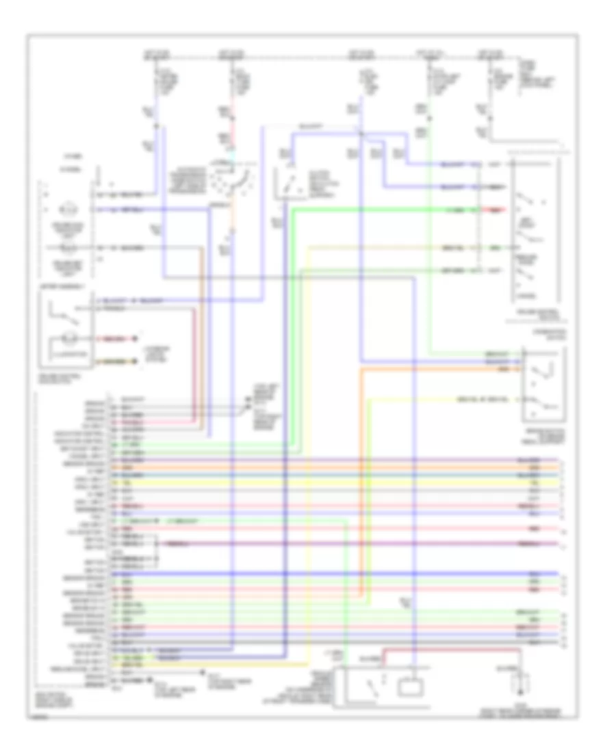
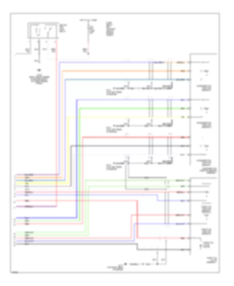
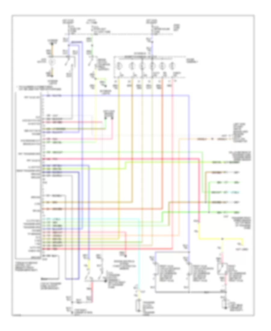
A/T Wiring Diagram for Isuzu Trooper Limited 2000
List of elements for A/T Wiring Diagram for Isuzu Trooper Limited 2000:
- (+)
- (-)
- (below rear of center console) g302
- (front left side of transmission) automatic transmission mode switch
- (left side of dash, above hood release lever) data link connector
- A/c compr rly
- A/c sys
- A/t oil temp warning ind
- Anti-lock brakes
- Automatic transmission
- Battery
- Brake input
- Brake switch (on brake pedal support)
- C-10 meter gauge fuse 10a
- C-14 stoplight a/t cont fuse 15a
- C-3 turn back fuse 15a
- C-8 engine fuse 15a
- Check trans ind
- Chk trans ind
- Dash fuse box
- Ect input
- Engine coolant temperature sensor (right front of engine)
- Etc grd
- Exterior lights
- F19
- F20
- F32
- F39
- F40
- F41
- F43
- F45
- F47
- F53
- F57
- F58
- F61
- F65
- F74
- F75
- F76
- F77
- F78
- F79
- Fl3 fuse 30a
- G105 (right rear corner of eng compt, on inner fender panel)
- G114 (top left rear of eng)
- G114 (top left rear of engine)
- G117 (top right rear of eng)
- Gauge assembly
- Ground
- Hot at all times
- Hot in on or start
- I-9
- Ignition
- Instrument cluster (a/t shift indicator control unit)
- Interior lights
- M-6
- M-7
- Oil temp ind
- Other models
- Pcm main relay
- Pnk
- Power
- Power drive ind
- Power/ winter switch
- Powertrain control module (right side of engine compt)
- Pressure control solenoid
- Pwr drv ind
- Pwr sw input
- R or l range
- Red
- Ref volt
- Relay/ fuse box
- S models
- S10
- S20
- S22
- S23
- S29
- S31
- S32
- S33
- S38
- S40
- S43
- S45
- S46
- S47
- S49
- S51
- S53
- S55
- S66
- S72
- S76
- Send grd
- Serial data
- Shift sol a
- Shift sol b
- Shift solenoid a
- Shift solenoid b
- Tcc
- Tft sens
- Throttle position sensor 1
- Throttle position sensor 2
- Throttle valve assembly (top front of engine)
- Torque converter clutch pwm solenoid
- Tps1
- Tps1 grd
- Tps2 grd
- Tps2 sig
- Trans fluid temperature sensor
- Trans pos in
- Trans spd sens
- Transmission speed sensor (on top rear of transmission)
- Win drv ind
- Win sw input
- Winter
- Winter drive ind
WARNING SYSTEMS
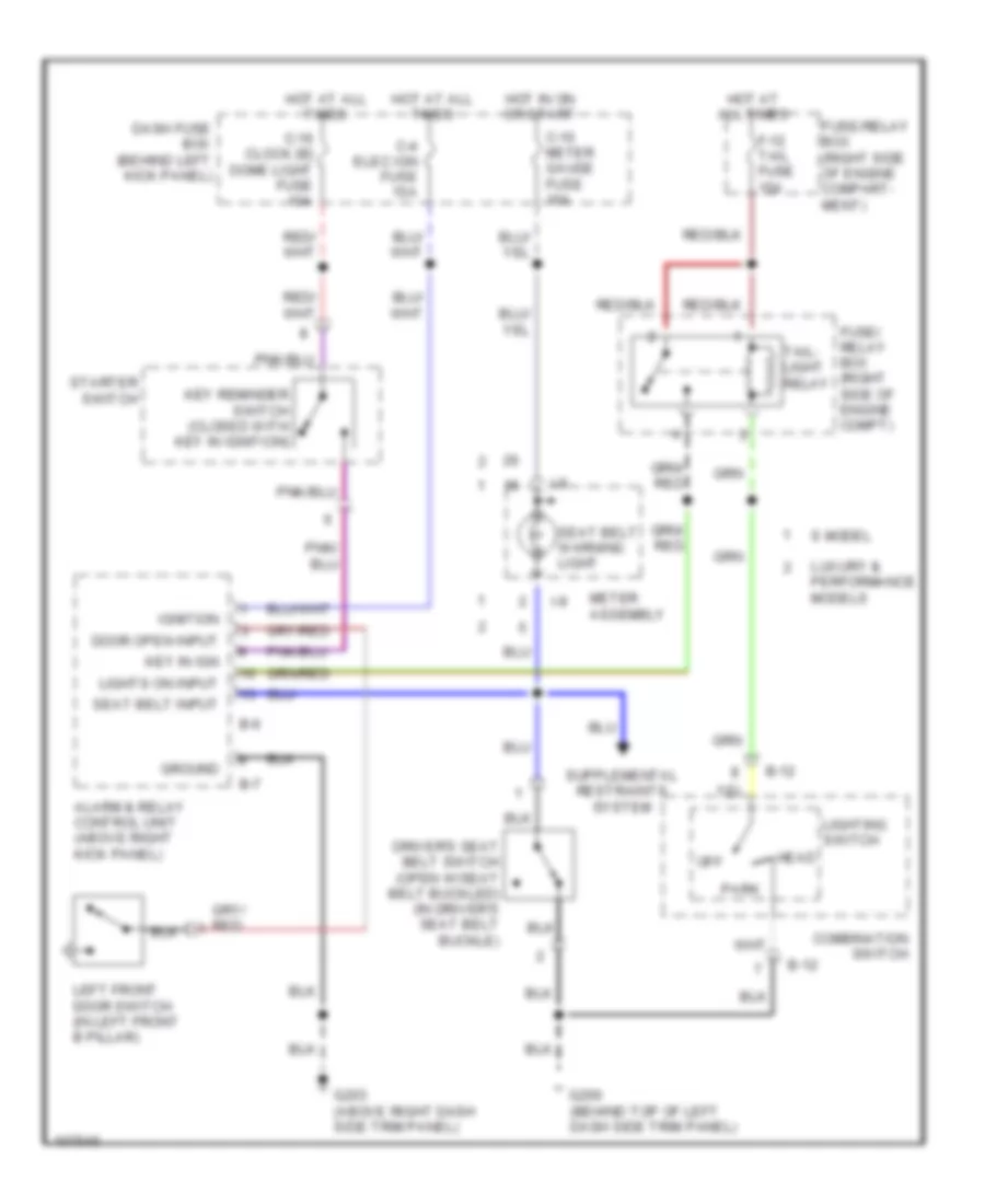
Warning System Wiring Diagrams for Isuzu Trooper Limited 2000
List of elements for Warning System Wiring Diagrams for Isuzu Trooper Limited 2000:
- door open input
- Alarm & relay control unit (above right kick panel)
- B-12
- B-6
- B-7
- C-10 meter gauge fuse 10a
- C-16 clock [b] dome light fuse 10a
- C-4 elec ign fuse 15a
- Combination switch
- Dash fuse box (behind left kick panel)
- Driver's seat belt switch (open w/seat belt buckled) (in driver's seat belt buckle)
- F-12 tail fuse 15a
- Fuse/ relay box (right side of engine compt)
- Fuse/relay box (right side of engine compart- ment)
- G200 (behind top of left dash side trim panel)
- G203 (above right dash side trim panel)
- Ground
- Head
- Hot at all times
- Hot in on or start
- I-9
- Ignition
- Key in ign
- Key reminder switch (closed with key in ignition)
- Left front door switch (in left front b pillar)
- Lighting switch
- Lights on input
- Luxury & performance models
- Meter assembly
- Off
- Park
- S model
- Seat belt input
- Seat belt warning light
- Starter switch
- Tail- light relay
WIPER/WASHER
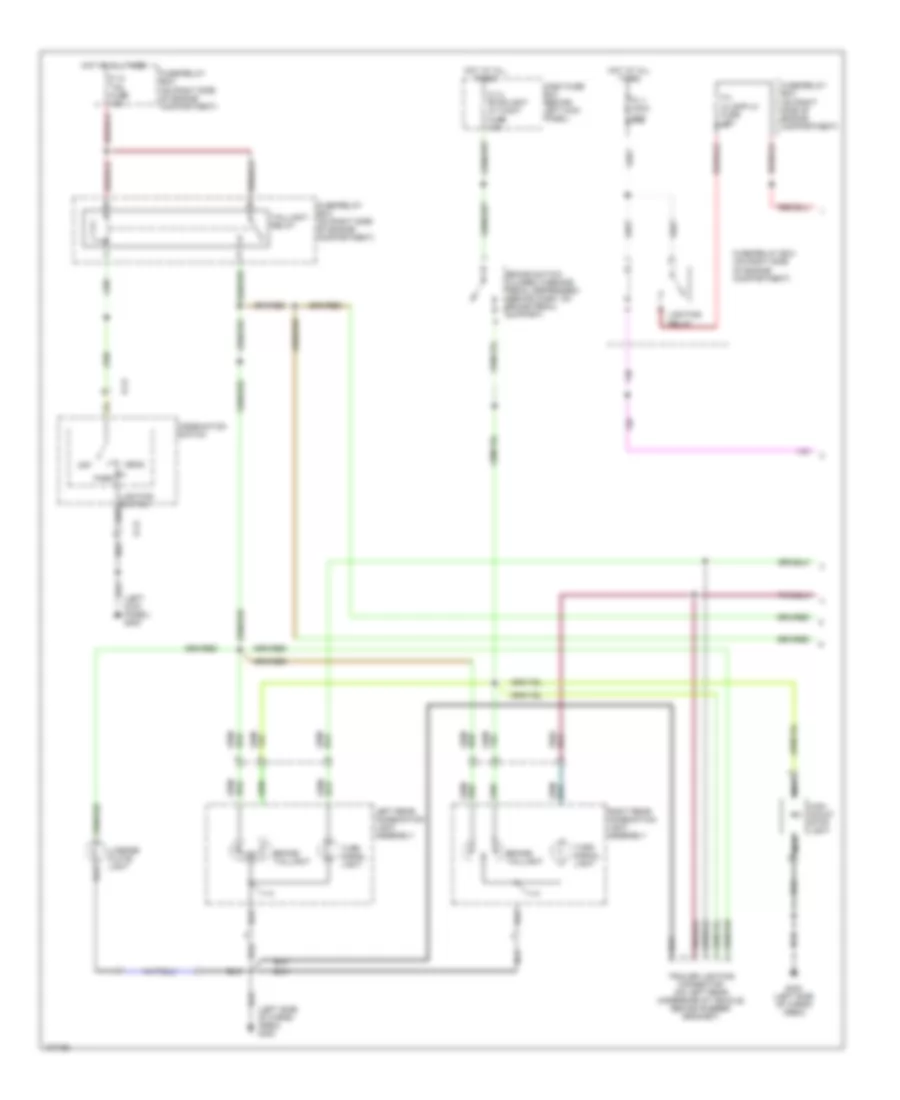
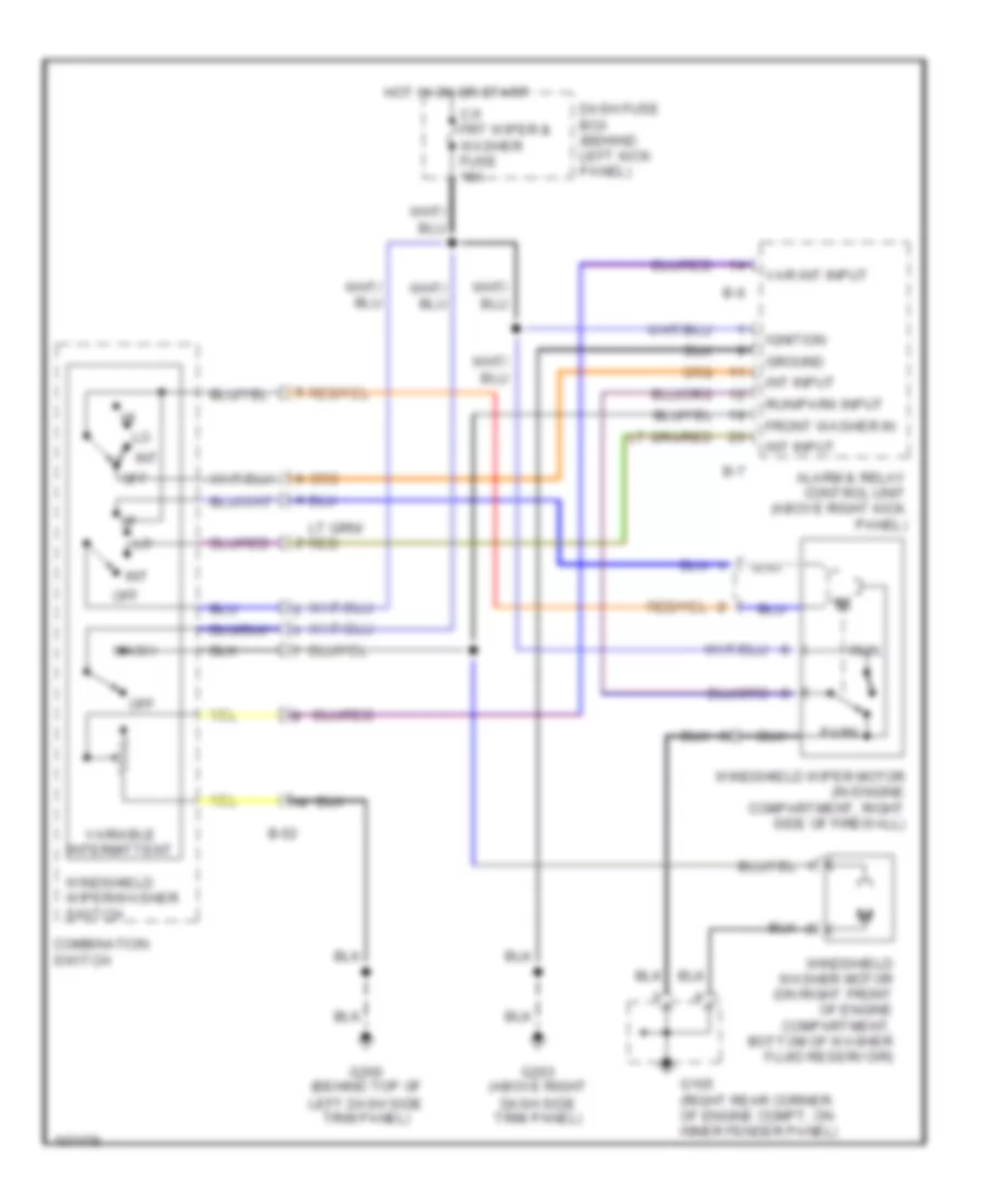
Front Wiper/Washer Wiring Diagram, Luxury & Performance for Isuzu Trooper Limited 2000
List of elements for Front Wiper/Washer Wiring Diagram, Luxury & Performance for Isuzu Trooper Limited 2000:
- Alarm & relay control unit (above right kick panel)
- B-52
- B-6
- B-7
- C-5 frt wiper & washer fuse 15a
- Combination switch
- Dash fuse box (behind left kick panel)
- Front washer in
- G105 (right rear corner of engine compt, on inner fender panel)
- G200 (behind top of left dash side trim panel)
- G203 (above right dash side trim panel)
- Ground
- Hot in on or start
- Ignition
- Int
- Int input
- Off
- Park
- Run
- Run/park input
- Var int input
- Variable intermittent
- Wash
- Windshield washer motor (on right front of engine compartment, bottom of washer fluid reservoir)
- Windshield wiper motor (in engine compartment, right side of firewall)
- Windshield wiper/washer switch
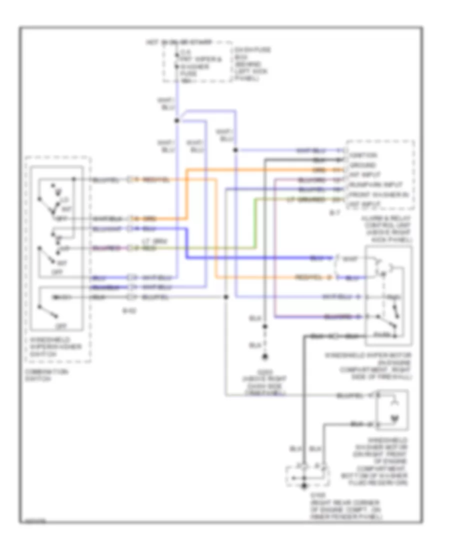
Front Wiper/Washer Wiring Diagram, S Model for Isuzu Trooper Limited 2000
List of elements for Front Wiper/Washer Wiring Diagram, S Model for Isuzu Trooper Limited 2000:
- Alarm & relay control unit (above right kick panel)
- B-52
- B-7
- C-5 frt wiper & washer fuse 15a
- Combination switch
- Dash fuse box (behind left kick panel)
- Front washer in
- G105 (right rear corner of engine compt, on inner fender panel)
- G203 (above right dash side trim panel)
- Ground
- Hot in on or start
- Ignition
- Int
- Int input
- Off
- Park
- Run
- Run/park input
- Wash
- Windshield washer motor (on right front of engine compartment, bottom of washer fluid reservoir)
- Windshield wiper motor (in engine compartment, right side of firewall)
- Windshield wiper/washer switch
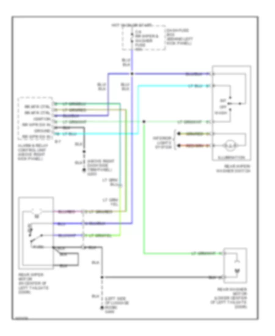
Rear Wiper/Washer Wiring Diagram for Isuzu Trooper Limited 2000
List of elements for Rear Wiper/Washer Wiring Diagram for Isuzu Trooper Limited 2000:
- (left side of luggage room) g400
- Alarm & relay control unit (above right kick panel)
- B-7
- C-6 rr wiper & washer fuse 10a
- Dash fuse box (behind left kick panel)
- Dash side trim panel) g203
- Ground
- Hot in on or start
- Ignition
- Illumination
- Int
- Interior lights system
- Off
- Park
- Rear washer motor (lower center of left tailgate door)
- Rear wiper motor (in center of left tailgate door)
- Rear wiper/ washer switch
- Rr mtr ctrl
- Rr wpr sw in
- Run
- Wash

 Čeština
 Dansk
Dansk Deutsch
 Ελληνικά
 English
 English
 Español
 Suomi
Suomi Français
 Français
 עברית
עברית Hrvatski
 Magyar
 Italiano
 日本語
日本語 한국어
한국어 Nederlands
 Polski
 Português
 Română
 Русский
 Slovenčina
 Slovenščina
 Svenska
 Türkçe
 中文 (中国)