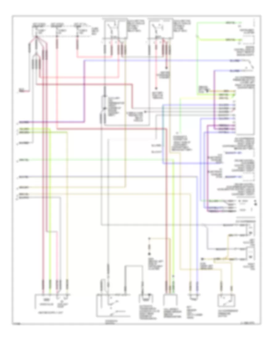
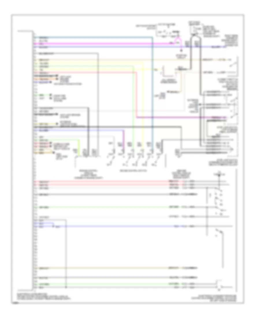
AIR CONDITIONING
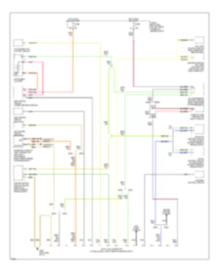
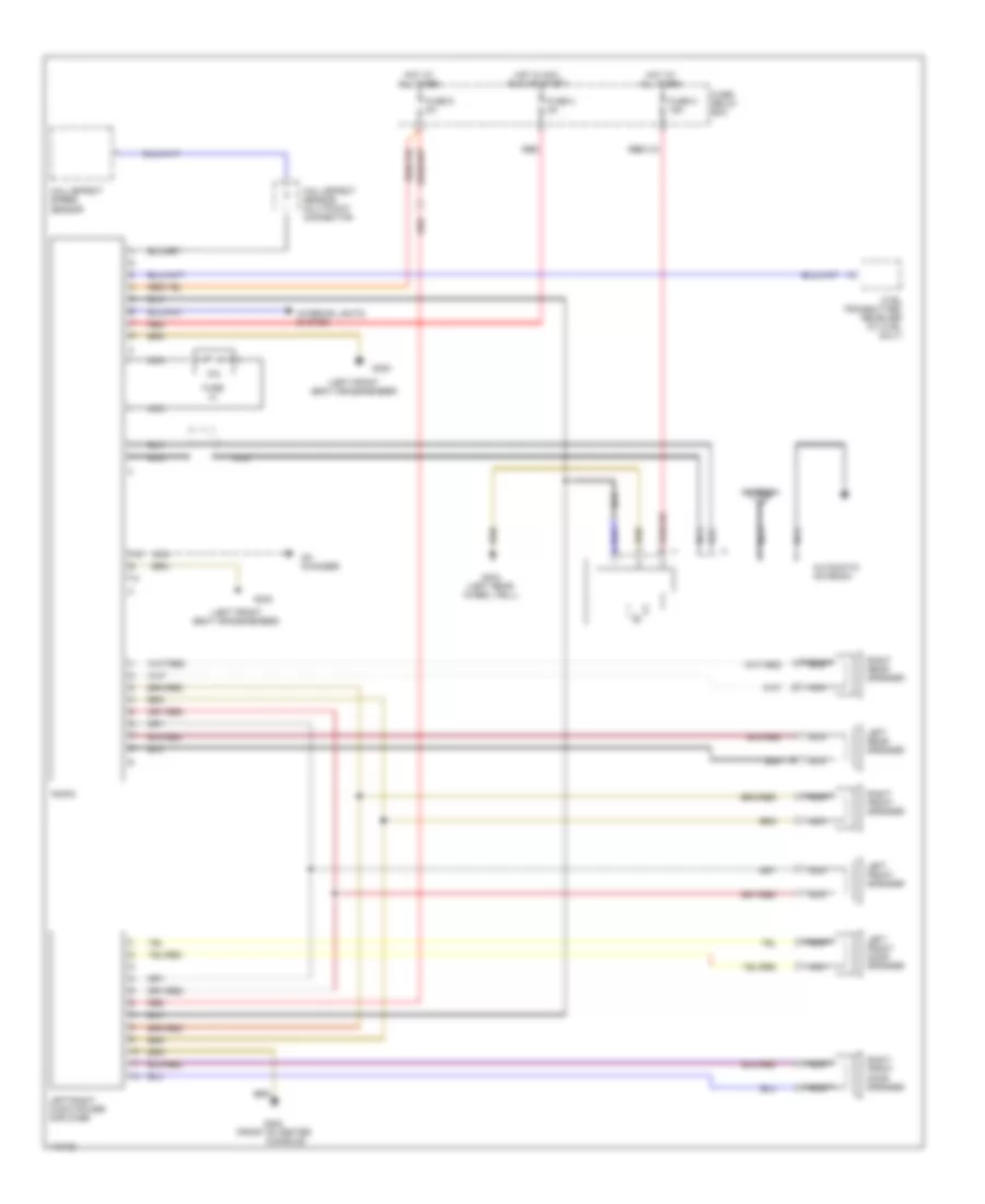
Air Conditioning Wiring Diagrams (1 of 2) for Mercedes-Benz E320 1994
 https://portal-diagnostov.com/license.html
Automotive Electricians Portal FZCO
Automotive Electricians Portal FZCO
https://portal-diagnostov.com/license.html
https://portal-diagnostov.com/license.html
Automotive Electricians Portal FZCO
Automotive Electricians Portal FZCO
List of elements for Air Conditioning Wiring Diagrams (1 of 2) for Mercedes-Benz E320 1994:
- (behind left
- (right side of steering column)
- A/c pushbutton control unit
- Acc
- Blower motor
- C 1995 vftc
- Center outlet flap
- Climate control auxiliary fuse 30a (left side of component compartment)
- Cluster)
- Defrost flap long stroke
- Defrost flap short stroke
- Diverter flap
- Electronic blower control (rear of engine compartment)
- Evaporator temperature sensor
- Fresh/ recirc flap long stroke
- Fresh/ recirc flap short stroke
- Fresh/recirculated air switch
- G202
- G202 (behind left side of instrument cluster)
- Heater core temperature sensor (below radio)
- Hot at all times
- Ignition switch
- In-car temperature sensor (part of dome lamp)
- In-car temperature sensor aspirator (top of passenger's footwell)
- Instrument
- Interior lights system
- Legroom flap
- Nca
- Off
- Outside temperature sensor (right side of component compartment)
- Run
- Side of
- Start
- Switch- over valve unit (above passenger's footwell area)
- Test connector (left of battery)
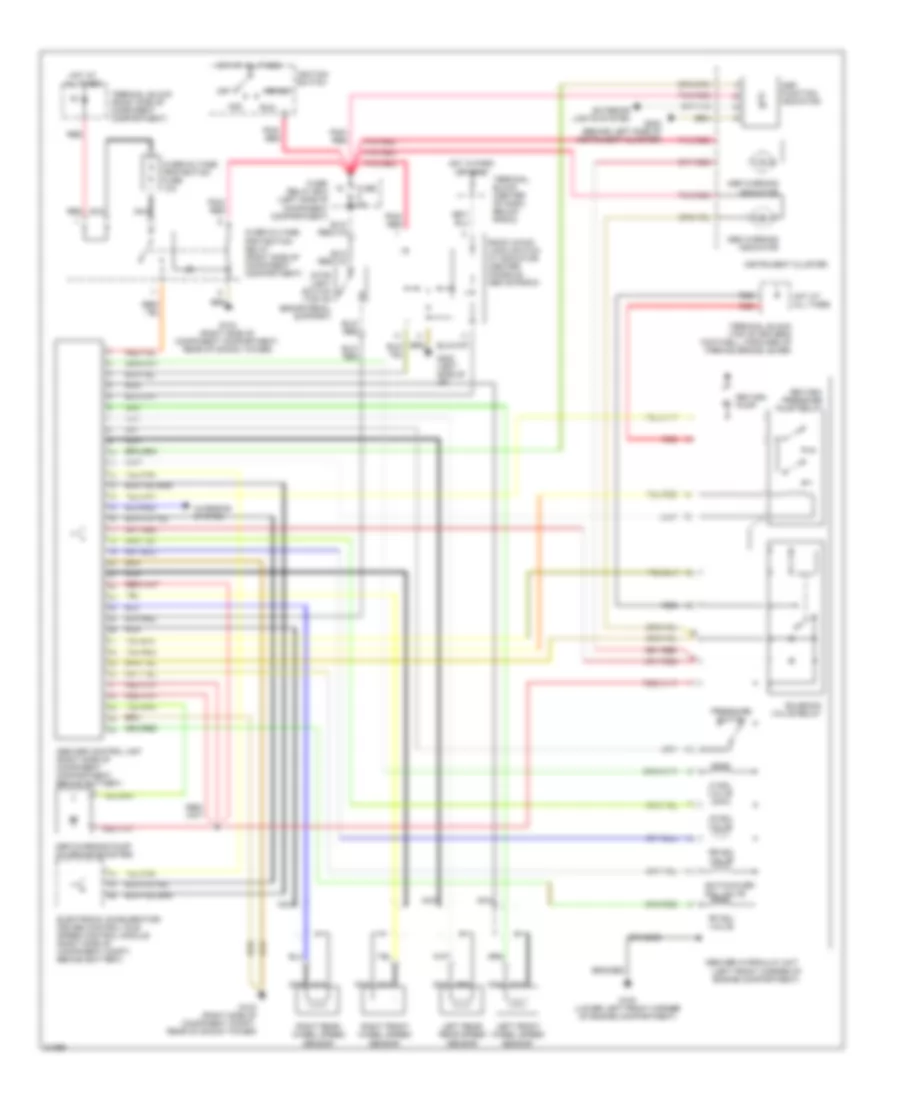
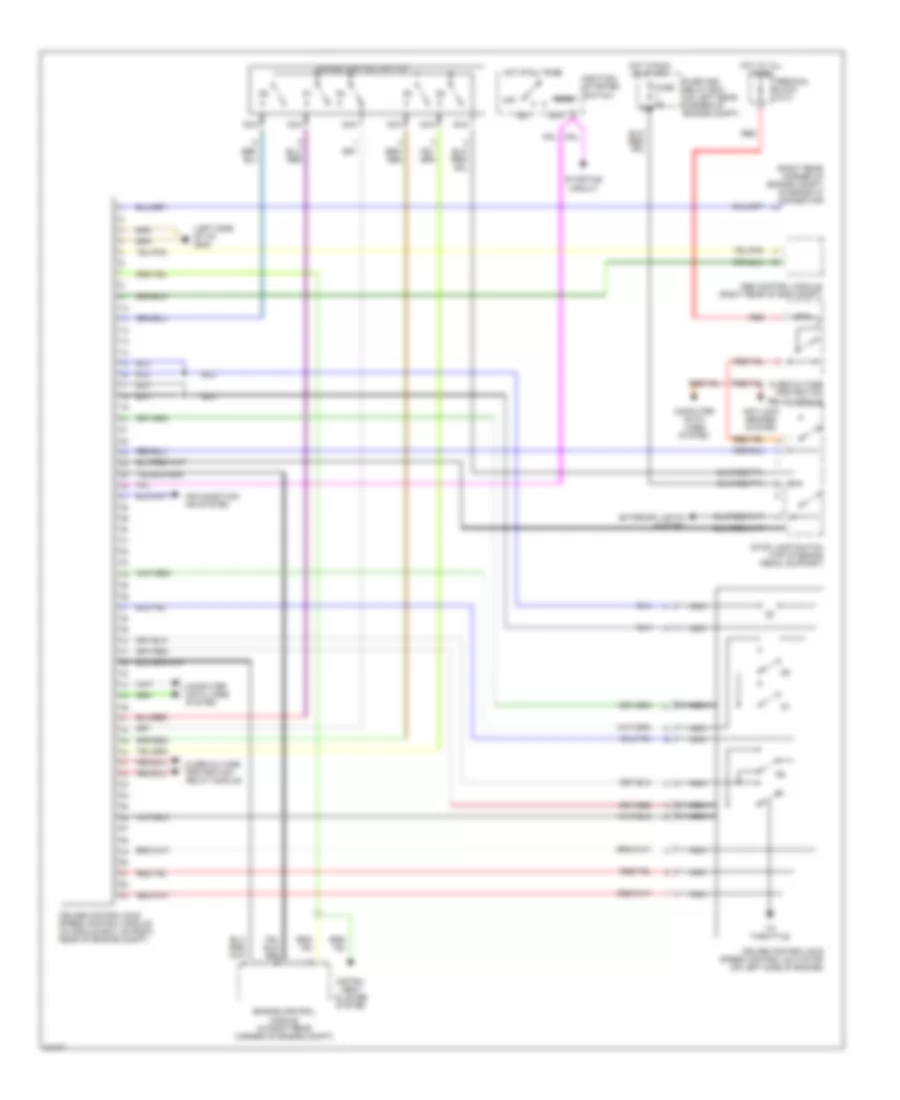
Air Conditioning Wiring Diagrams (2 of 2) for Mercedes-Benz E320 1994
List of elements for Air Conditioning Wiring Diagrams (2 of 2) for Mercedes-Benz E320 1994:
- (behind battery) g105
- (right side of
- 15a
- 30a
- A/c compressor
- A/c compressor control module (right side of component compartment, behind battery)
- A/c compressor pressure switch
- A/c compressor pressure switch (lower left front of engine compartment)
- Automatic transmission kickdown valve (right rear corner of transmission)
- Auxiliary fan preresistor (front corner of engine compart- ment)
- Auxiliary fan relay module (stage 1) (in fuse/ relay box)
- Auxiliary fan relay module (stage 2) (in fuse/ relay box)
- Battery positive terminal
- Behind battery)
- C 1995 vftc
- Compartment,
- Component
- Coolant pump
- Cruise control/ idle speed control module (right side of component compt)
- Cruise control/ idle speed/electronic accelerator control module (right side of component compt)
- Diagnostic connector
- Ect
- Engine control module (right rear of engine compt)
- Fuse 5 8a
- Fuse 7 16a
- Fuse d 16a
- Fuse/ relay box
- G106 (near left headlamp)
- G202 (behind left side of instrument cluster)
- Hall effect speed sensor (behind speedometer)
- Heated
- Hot at all times
- Hot in run or start
- Instrument cluster
- Kickdown switch
- Left auxiliary fan
- Monovalve
- Nca
- Overvoltage protection relay module
- Red
- Right auxiliary fan
- Sensor (a/c) (on cylinder head)
- W/ electronic acceler- ator
- W/o electronic acceler- ator
- Windshield washer
ANTI-LOCK BRAKES
Anti-lock Brake Wiring Diagrams, with Acceleration Slip Regulation for Mercedes-Benz E320 1994
List of elements for Anti-lock Brake Wiring Diagrams, with Acceleration Slip Regulation for Mercedes-Benz E320 1994:
- (left front corner of engine compartment)
- Abs warning indicator
- Abs/asr control unit (right side of component compartment, behind battery)
- Abs/asr hydraulic unit
- Acc
- Asr charging pump (on brake booster)
- Asr function indicator
- Asr warning indicator
- Braided
- Charging system
- Electronic accelerator/ cruise control/ idle speed control module (right side of component compt, behind battery)
- Exterior lights system
- Fuse 8a
- Fuse/ relay box (left side of component compartment)
- G100 (lower left front corner of engine compartment)
- G103 (right side of component compartment, rear of shock tower)
- G103 (right side of component compt, rear of shock tower)
- G202 (behind left side of instrument cluster)
- G202 (left side of i/p)
- Hot at all times
- Hot in park or head
- Ignition switch
- Instrument cluster
- Left front wheel speed sensor
- Left rear rear speed sensor
- Lf sol valve
- Lr sol valve
- Nca
- Off
- Overvoltage protection fuse 10a
- Overvoltage protection relay (right side of component compartment)
- Pnk/ red
- Pnk/red
- Pressure switch
- Red
- Return pump
- Return/ pressure pump relay
- Rf sol valve
- Right front wheel speed sensor
- Right rear wheel speed sensor
- Rr sol valve
- Run
- Snow chain logic switch w/ indicator (center console, above radio)
- Solenoid valve relay
- Start
- Stop light switch (top of brake pedal support)
- Switchover sol valve
- Terminal block (center of dash, below radio)
- Terminal block (right side of component compartment)
- Terminal block (top of driver's footwell, forward of parking brake lever)
Anti-lock Brake Wiring Diagrams, without Acceleration Slip Regulation for Mercedes-Benz E320 1994
List of elements for Anti-lock Brake Wiring Diagrams, without Acceleration Slip Regulation for Mercedes-Benz E320 1994:
- (left front corner of engine compartment)
- Abs control unit (right side of component compartment, in module box)
- Abs function ind.
- Abs hydraulic unit
- Acc
- Braid
- Charging system
- Differential rear speed sensor
- Engine control module (right rear corner of engine compt)
- Fuse 5 8a
- Fuse/ relay box
- Fuse/ relay box (left side of component compartment)
- G103 (right side of component compartment, rear of shock tower)
- G131 (left front of engine, on intake manifold)
- Hot at all times
- Hot in run or start
- Ignition switch
- Instrument cluster
- Left front wheel speed sensor
- Lf sol valve
- Nca
- Off
- Overvoltage protection fuse 10a
- Overvoltage protection relay (right side of component compartment)
- Pnk
- Pnk/ red
- Pump motor relay
- Rear axle sol valve
- Red
- Return pump
- Rf sol valve
- Right front wheel speed sensor
- Run
- Solenoid valve relay
- Start
- Stop light switch (top of brake pedal support)
- Terminal block (right side of component compartment)
- Terminal block (top of driver's footwell, forward of parking brake lever)
ANTI-THEFT
Anti-theft Wiring Diagram for Mercedes-Benz E320 1994
List of elements for Anti-theft Wiring Diagram for Mercedes-Benz E320 1994:
- Alarm horn
- Anti-theft alarm control unit (behind right front footrest)
- Arm
- Ata diode
- Ata status indicator
- Cf control module (beneath left side of rear seat)
- Connector block (behind driver's left kick panel)
- Disarm
- Exterior lights system
- Fuse 11 16a
- Fuse 12 16a
- Fuse 8a
- Fuse c 16a
- Fuse/ relay box
- G103 (right front shock tower)
- G202 (left side of dash)
- G206 (center of dash)
- G404 (left rear side of trunk)
- Headlights system
- Hood switch
- Hot at all times
- Hot in run or start
- Interior lights system
- Left front door lock actuator
- Left front door switch
- Left rear door switch
- Lock
- Radio
- Right front door lock actuator
- Right front door switch
- Right rear door switch
- Stop lamp switch
- Trunk lamp
- Trunk lamp switch
- Trunk lid lock actuator
- Unlock
- Warning buzzer switch (open w/ key in ignition)
- X42/13
COMPUTER DATA LINES
Data Link Connector Wiring Diagram for Mercedes-Benz E320 1994
List of elements for Data Link Connector Wiring Diagram for Mercedes-Benz E320 1994:
- 15r
- A/c compressor control module (right rear side of engine compt)
- A/c pushbotton control module
- Anti- theft system
- Asd control module (e300 only)
- Cc/isa control module (in module box, on right rear of engine compt)
- Center console roll bar malfunction indicator lamp (e320 cabriolet)
- Cruise control system
- Data link connector (in module box, right rear of engine compt)
- Diagnostic circuit
- Diagnostic module test connection (e320 only) (california) (right rear corner of engine compt)
- E300
- E320
- E320 only
- Ea/cc/isa control module (in module box, on right rear of engine compt)
- Engine control module (hfm-sfi) (e320 only) (right rear of engine compt)
- Fuse & relay box (on left rear corner of engine compt)
- Fuse 16a
- Fuse 8a
- G202 (left side of i/p)
- Hot in acc run or start
- Hot in run or start
- Infrared control module
- Instrument cluster
- Isc control module (e300 only)
- Nca
- Nca led
- Nca switch
- Overvoltage protection relay module
- Pnk
- Roll bar control module (e320 cabriolet) (behind dash)
- Srs control module (under center console)
- Srs ind
- W/ ea
- W/o ea
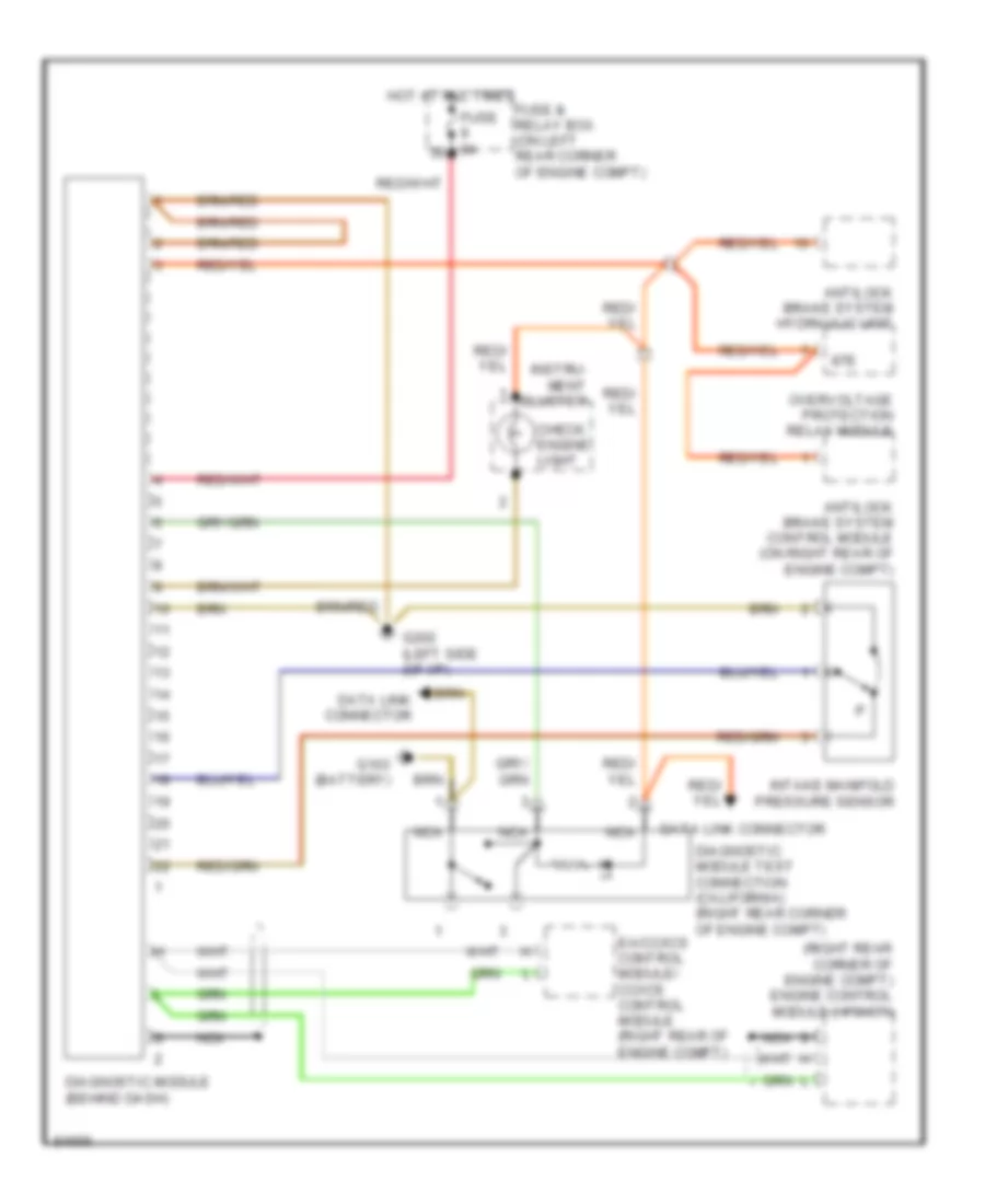
Diagnostic Socket Wiring Diagram for Mercedes-Benz E320 1994
List of elements for Diagnostic Socket Wiring Diagram for Mercedes-Benz E320 1994:
- (right rear corner of engine compt) engine control module (hfm-sfi)
- 87e
- Antilock brake system control module (on right rear of engine compt)
- Antilock brake system hydraulic unit
- Check engine light
- Data link connector
- Diagnostic module (behind dash)
- Diagnostic module test connection (california) (right rear corner of engine compt)
- Ea/cc/ics control module/ cc/ics control module (right rear of engine compt)
- Fuse & relay box (on left rear corner of engine compt)
- Fuse 8a
- G103 (battery)
- G202 (left side (of i/p)
- Hot at all times
- Instru- ment cluster
- Intake manifold pressure sensor
- Nca
- Overvoltage protection relay module
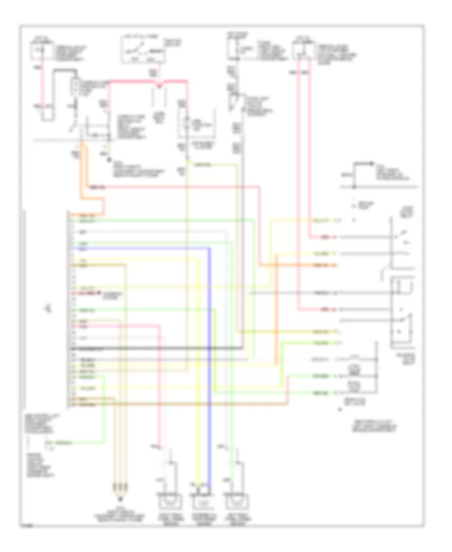
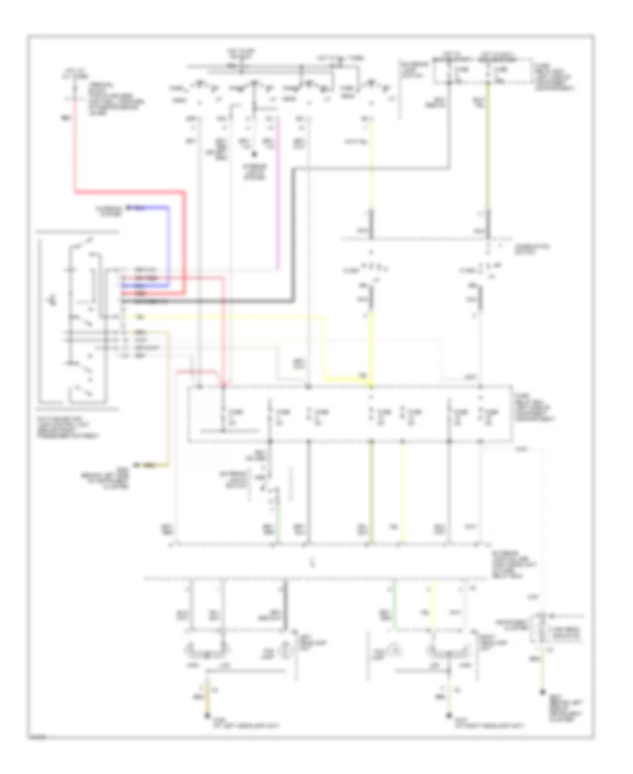
COOLING FAN
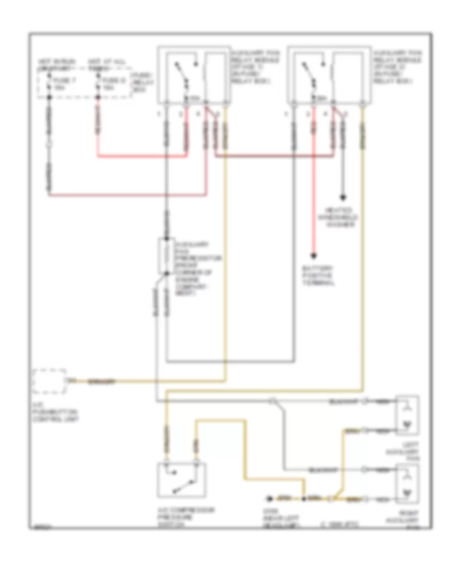
Cooling Fan Wiring Diagram for Mercedes-Benz E320 1994
List of elements for Cooling Fan Wiring Diagram for Mercedes-Benz E320 1994:
- 15a
- 30a
- A/c compressor pressure switch
- A/c pushbutton control unit
- Auxiliary fan preresistor (front corner of engine compart- ment)
- Auxiliary fan relay module (stage 1) (in fuse/ relay box)
- Auxiliary fan relay module (stage 2) (in fuse/ relay box)
- Battery positive terminal
- C 1995 vftc
- Fuse 7 16a
- Fuse d 16a
- Fuse/ relay box
- G106 (near left headlamp)
- Heated windshield washer
- Hot at all times
- Hot in run or start
- Left auxiliary fan
- Nca
- Red
- Right auxiliary fan
CRUISE CONTROL
Cruise/Idle Speed Control Wiring Diagram for Mercedes-Benz E320 1994
List of elements for Cruise/Idle Speed Control Wiring Diagram for Mercedes-Benz E320 1994:
- (left side of i/p) g202
- (right rear corner of engine compt) diagnostic connector
- 15a
- Abs control module (right rear of eng compt)
- Acc
- Air condition- ing system
- Ant-lock brakes system
- Computer data lines system
- Cruise control switch
- Cruise control/idle speed control actuator (on left side of engine)
- Cruise control/idle speed control module (in module box, on right rear of engine compt)
- Engine control module (in right rear corner of engine compt)
- Exterior lights system
- Fuse 8a
- Fuse and relay box (on left rear corner of engine compt)
- Hot at all times
- Hot in run or start
- Ignition/ starter switch
- Instru- ment cluster system
- Nca
- Off
- Overvoltage protection relay module
- Red
- Run
- Start
- Starting circuit
- Stop lamp switch (top of brake pedal support)
- Terminal block x4/10
- To throttle
Electronic Accelerator/Cruise/Idle Speed Control Wiring Diagram for Mercedes-Benz E320 1994
List of elements for Electronic Accelerator/Cruise/Idle Speed Control Wiring Diagram for Mercedes-Benz E320 1994:
- (right rear corner of engine compt) diagnostic connector
- Abs/asr control module (right rear of engine compt)
- Acc
- Air conditioning system
- Anti-lock brakes system
- Closed throttle position switch (on top of accelerator bracket)
- Computer data lines system
- Cruise control switch
- Electronic accelerator/ cruise control/idle speed control module (in module box, on right rear of engine compt)
- Electronic accelerator/cruise control/idle speed control actuator (on left side of engine)
- Engine control module (in right rear corner of engine compt)
- Exterior lamp failure monitor- ing module
- Exterior lights system (backup lamp switch)
- Fuse 8a
- Fuse and relay box (on left rear corner of engine compt)
- G202 (left side of i/p)
- Hall-effect speed sensor
- Hot at all times
- Hot in run or start
- Ignition/starter switch
- Nca
- Off
- Overvoltage protection relay module
- Run
- Start
- Starting circuit
- Stop lamp switch (top of brake pedal support)
- Stop lamp switch intermediate connector (below steering column)
- To throttle
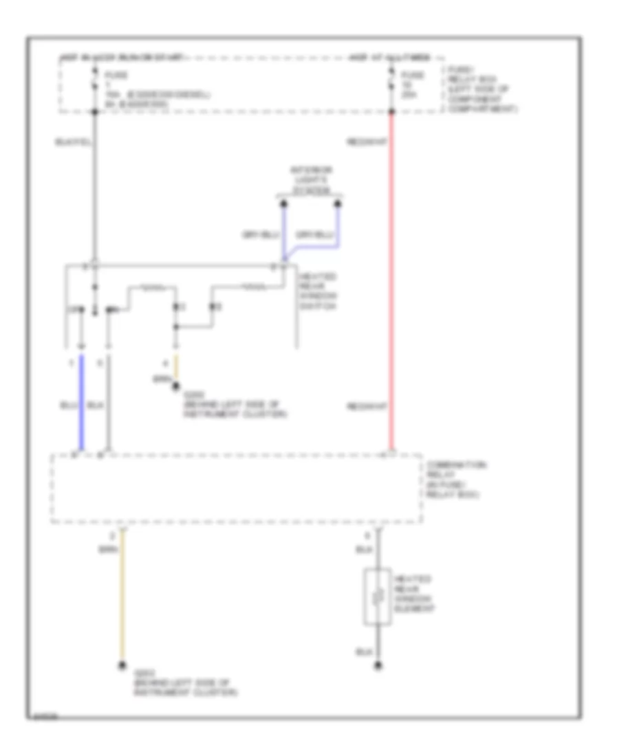
DEFOGGERS
Defogger Wiring Diagram for Mercedes-Benz E320 1994
List of elements for Defogger Wiring Diagram for Mercedes-Benz E320 1994:
- (e320/e300 diesel)
- (e420/e500)
- Combination relay (in fuse/ relay box)
- Fuse 16a 8a
- Fuse 25a
- Fuse/ relay box (left side of component compartment)
- G202 (behind left side of instrument cluster)
- Heated rear window element
- Heated rear window switch
- Hot at all times
- Hot in accy,run or start
- Interior lights system
- Off
ENGINE PERFORMANCE
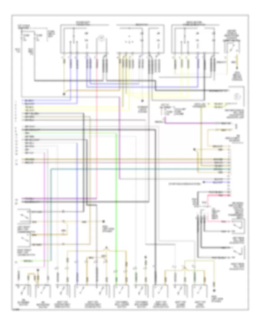
3.2L
3.2L, Engine Performance Wiring Diagrams (1 of 2) for Mercedes-Benz E320 1994
List of elements for 3.2L, Engine Performance Wiring Diagrams (1 of 2) for Mercedes-Benz E320 1994:
- (center console)
- (in right component compt.)
- 15a
- 15u
- 30z
- 30a
- 40a
- 87e
- 87m
- 87u
- A/c comp. control module
- Acc
- Auxiliary fan relay module
- Battery
- Canada
- Cc/isc control module
- Computer data lines
- Data link connector (dtc readout) (in right component compt.)
- Ea/cc/isc control module
- Electronic clock/ tachometer
- Engine control module (hfm-sfi) (in right component compt.)
- Fuel pump
- Fuel pump relay module
- Fuse & relay box
- Fuse 16a
- Fuse 8a
- G105 (battery)
- G302
- Hot at all times
- Hot in run or start
- Ignition switch
- Lock
- Nca
- O2s 1 (before
- Overvoltage protection relay module (in right component compt.)
- P/n
- Pnk/ red
- Pnk/red
- Purge control valve
- Red
- Run
- Solid state
- Start
- Starter
- Starter lock- out relay module
- Starter lock-out/ backup lamp switch
- Terminal block
- Transmission overload protection switch
- Twc)
- U.s.
- Upshift delay switch- over valve
- W/ ea
- W/o ea
3.2L, Engine Performance Wiring Diagrams (2 of 2) for Mercedes-Benz E320 1994
List of elements for 3.2L, Engine Performance Wiring Diagrams (2 of 2) for Mercedes-Benz E320 1994:
- (left side
- (right side
- Adjustable camshaft timing solenoid
- Camshaft position sensor
- Crankshaft position sensor
- Egr switchover valve
- Electro- magnetic secondary air injection pump clutch
- Engine control module (in right component compartment)
- Engine coolant temperature sensor
- G105 (battery)
- G125 (top front of engine)
- Hot film mass air flow sensor
- Hot in run or start
- Ignition coil #1
- Ignition coil #2
- Ignition coil #3
- Inj. #1
- Inj. #2
- Inj. #3
- Inj. #4
- Inj. #5
- Inj. #6
- Intake air temperature sensor
- Knock
- Nca
- Of engine)
- Pnk
- Pnk/ red
- Pnk/red
- Resonance intake manifold switchover valve
- Secondary air injection pump switchover valve
- Sensor 1
- Sensor 2
- Solid state
- Spark plug #1
- Spark plug #2
- Spark plug #3
- Spark plug #4
- Spark plug #5
- Spark plug #6
- Terminal block
EXTERIOR LIGHTS
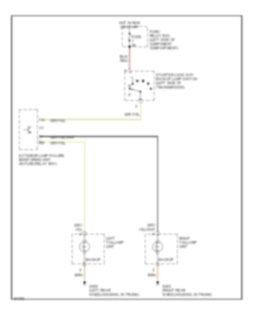
Back-up Lamps Wiring Diagram for Mercedes-Benz E320 1994
List of elements for Back-up Lamps Wiring Diagram for Mercedes-Benz E320 1994:
- Backup
- Exterior lamp failure monitoring unit (in fuse/relay box)
- Fuse 8a
- Fuse/ relay box (left side of component compartment)
- G402 (left rear wheelhousing, in trunk)
- G403 (right rear wheelhousing, in trunk)
- Hot in run or start
- Left taillamp unit
- Right taillamp unit
- Starter lock out/ backup lamp switch (left side of transmission)
Exterior Lamps Wiring Diagram for Mercedes-Benz E320 1994
List of elements for Exterior Lamps Wiring Diagram for Mercedes-Benz E320 1994:
- (behind left side of instrument cluster)
- 49a
- 58l
- 58r
- Audible turn solenoid
- Back-up light circuit
- Backup
- Center high
- Combination relay
- Combination switch
- Ext lamp outage ind
- Exterior lamp failure monitoring unit (in fuse/relay box)
- Exterior lamp switch
- Fog
- Fuse 8a
- Fuse/ relay box (left side of component compartment)
- Fuse/relay box
- G106 (left front of engine compt)
- G107 (right front of engine compt)
- G202
- G202 (behind left side of instrument cluster)
- G202 (left side of i/p)
- G402 (left rear wheelhousing, in trunk)
- G403 (right rear wheelhousing, in trunk)
- Hazard flasher switch
- Head
- Headlights system
- Hot at all times
- Hot in off & accy
- Hot in run or start
- Instrument cluster
- Interior lights system
- K30
- Left headlamp unit
- Left taillamp unit
- Left turn indicator
- Marker
- Marker (except wagon)
- Mounted stop lamp
- Off
- P30
- Park
- Right headlamp unit
- Right license plate lamp
- Right taillamp unit
- Right turn indicator
- Standing/ parking/ turn lamp
- Stop
- Stop lamp switch (top of brake pedal, on bracket)
- Tail
- Turn
- Turn signal switch
GROUND DISTRIBUTION
Ground Distribution Wiring Diagram for Mercedes-Benz E320 1994
List of elements for Ground Distribution Wiring Diagram for Mercedes-Benz E320 1994:
- A/c compressor control module, egr resonance intake manifold control module, pressure control flap switchover valve, resonance intake manifold switchover valve, a/c compressor cut-out/egr microswitch, ect sensor, isc control module, data link connector, overvoltage protection relay module, fuel pump relay module, upshift delay switchover valve, oxygen sensor 1, diagnostic module test connector, abs control module, asd control module, fanfare horns, right turn signal/side marker lamp, right front brake pad wear sensor, engine coolant level switch, anti theft alarm control module, right headlamp unit
- Antilock brake system control module, heated oxygen sensor, secondary air injection pump switchover valve, electromagnetic secondary air injection pump clutch, module box blower motor, ea/cc/isc control module, data link connector
- Auto dimming inside rearview mirror, sliding/pop-up roof switch, dome/reading lamp
- Battery
- Convenience control module, left power soft top valve block
- Cst/rb hydraulic unit, rb switches
- Di control module, diagnostic socket/ terminal block
- Electrolytic capacitor, transmission cooling fan relay module, transmission oil cooling fan, fanfare horns, right turn signal/side marker lamp, headlamp washer pump, right headlamp wiper motor, windshield washer pump
- G100 (front of left front fender)
- G103 (right front shock tower)
- G106 (behind left headlamp)
- G107 (behind right headlamp)
- G125 (front of engine)
- G202 (behind left side of instrument cluster)
- G302 (front of center console)
- G310 (behind right rear seat)
- G403 (right rear wheel well)
- G404 (left rear wheel well)
- G406 (center of tailgate)
- G908 (at front dome lamp)
- Hot film mass air flow sensor, abs/asr control module
- Hot wire mass air flow sensor, rhr release switch, rhr release valve, electromagnetic secondary air injection pump switchover valve, electromagnetic secondary air injection pump clutch
- Left sequential multiport fuel injection control module, diagnostic module, diagnostic module test connector, base module
- Left taillamp unit, rear window washer pump, ctel transmitter-receiver
- Overvoltage protection relay module, left taillamp unit, fuel level sensor, cf control module, sliding/ pop-up roof drive assembly, license plate lamps, center high mounted stop lamp, ctel transmitter/ receiver, automatic antenna
- Preglow time limit relay module, instrument cluster, heated windshield washer system thermoswitch
- Radio
- Rb control module
- Rb valve block, soft top switches
- Rear window defroster element (convertible)
- Right power soft top valve block, power soft top control module, soft top fabric bow "raised" switch, power soft top switch, rb switch, power soft top test connection
- Right turn signal/ side marker lamp, engine coolant level switch
- Tailgate closing assist, center high mounted stop lamp, license plate lamps, rear window wiper motor, rear window intermittent wiper timer
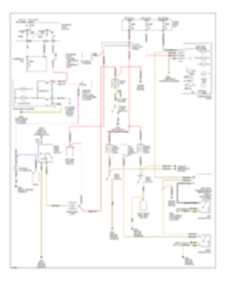
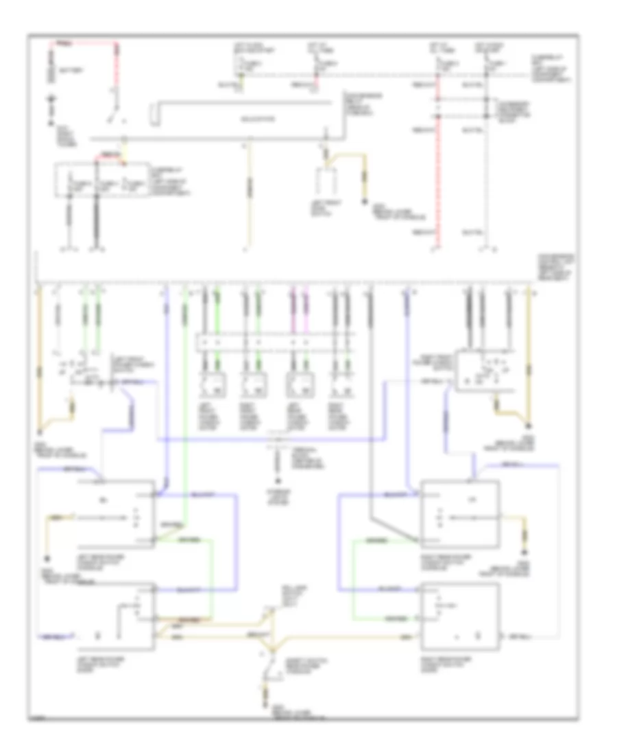
HEADLIGHTS
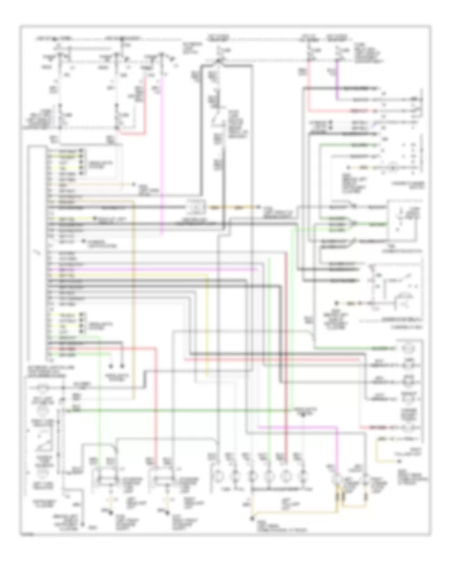
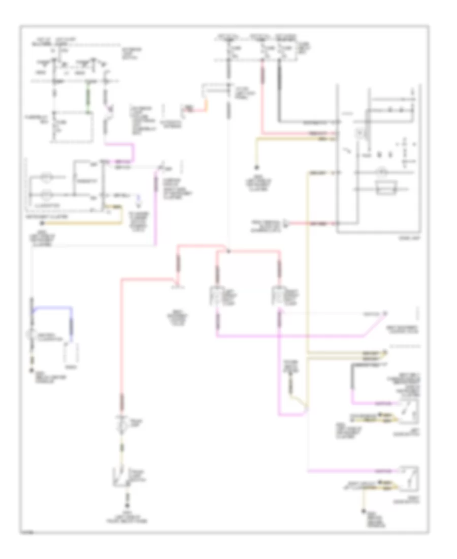
Headlamps Wiring Diagram, with DRL for Mercedes-Benz E320 1994
List of elements for Headlamps Wiring Diagram, with DRL for Mercedes-Benz E320 1994:
- 56a
- 56b
- 58l
- 58r
- Charging system
- Combination switch
- Daytime driving lamp control unit (behind front passenger footrest)
- Exterior lamp failure monitoring unit (in fuse/ relay box)
- Exterior lamp switch
- Exterior lights switch
- Flash
- Fog lamp
- Fuse 16a
- Fuse 8a
- Fuse/ relay box (left side of component compartment)
- G106 (at left headlamp unit)
- G107 (at right headlamp unit)
- G202 (behind left side of instrument cluster)
- Head
- High
- High beam indicator
- Hot at all times
- Hot in accy, run or start
- Hot in off or accy
- Hot in run or start
- Instrument cluster
- Interior lights system
- K30
- Left headlamp unit
- Low
- Nca
- Nse
- Off
- P30
- Park
- Red
- Right headlamp unit
- Terminal block (top of driver's footwell, forward of parking brake lever)
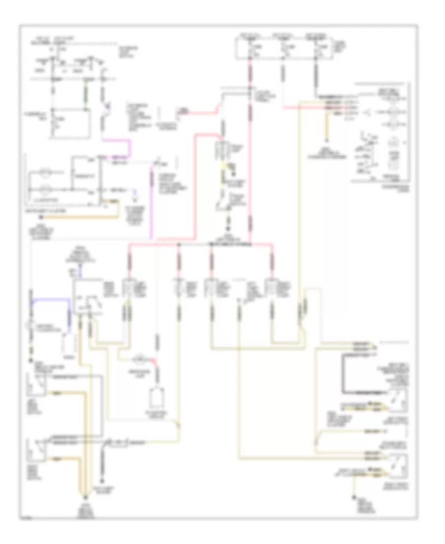
Headlamps Wiring Diagram, without DRL for Mercedes-Benz E320 1994
List of elements for Headlamps Wiring Diagram, without DRL for Mercedes-Benz E320 1994:
- 56a
- 56b
- 58l
- Combination switch
- Exterior lamp failure monitoring unit (in fuse/ relay box)
- Exterior lamp switch
- Flash
- Fog
- Fog lamp
- Fuse 16a
- Fuse 8a
- Fuse/ relay box (left side of component compartment)
- G106 (at left headlamp unit)
- G107 (at right headlamp unit)
- G202 (behind left side of instrument cluster)
- Head
- High
- High beam indicator
- Hot at all times
- Hot in accy, run or start
- Hot in park or head
- Instrument cluster
- Left headlamp unit
- Low
- Nca
- Nse
- Off
- Park
- Right headlamp unit
HORN
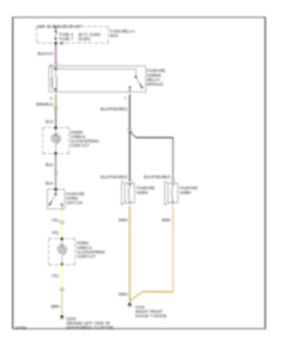
Horn Wiring Diagram for Mercedes-Benz E320 1994
List of elements for Horn Wiring Diagram for Mercedes-Benz E320 1994:
- (exc. e420) (e420)
- Fanfare horn
- Fanfare horn switch
- Fanfare horns relay module
- Fuse 6 fuse 7 8a
- Fuse/relay box
- G103 (right front shock tower)
- G202 (behind left side of instrument cluster)
- Horn/ airbag clockspring contact
- Hot in run or start
INSTRUMENT CLUSTER
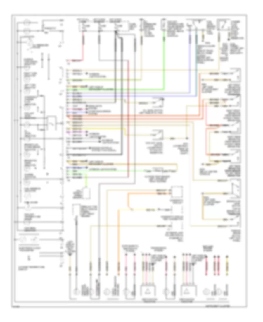
Instrument Cluster Wiring Diagram for Mercedes-Benz E320 1994
List of elements for Instrument Cluster Wiring Diagram for Mercedes-Benz E320 1994:
- (diesel)
- (fuse/relay box)
- (gasoline)
- (left side of instru- ment cluster) g202
- (left side of instrument cluster)
- (left side of instrument cluster) g202
- (sedan & coupe: left side of trunk, below hinge) (wagon: behind left rear quarter panel)
- (top of brake fluid reservoir)
- 58d
- Abs indicator
- Anti-lock brakes system
- Asd function indicator
- Asr function indicator
- Asr indicator
- Audible turn signal indicator
- Brake fluid & park brake indicator
- Brake fluid level switch
- Brake pad wear indicator
- Charge indicator
- Coolant level indicator
- Coolant level switch (lower front of coolant reservoir)
- Coolant temperature gauge
- Coolant temperature gauge sensor (left side of engine, above intake manifold)
- Diagnostic module 1
- Diagnostic module test connection
- Electronic clock/ tachometer
- Engine controls system (tach signal)
- Engine indicator check
- Exterior lamp failure ind
- Exterior lamp failure module
- Exterior lights system
- Fluid reservoir)
- Fuel gauge
- Fuel level sensor (top of fuel tank)
- Fuel reserve indicator
- Fuse 8a
- Fuse/ relay box
- G101 (lower right front of engine compt)
- G101 g106 (diesel) (gas) (lower (lower left front of eng compt) front of engine compt)
- G202
- G202 (left side of instrument cluster)
- G302 (below center console)
- G404
- Hall effect speed sensor
- Headlights system
- High beam indicator
- Hot at all times
- Hot in run or start
- Illumination
- Indicator asd
- Indicator preglow
- Indicator srs
- Instrument cluster
- Interior lights system
- Left front brake pad wear sensor (in left front brake pad)
- Left rear brake pad brake pad wear sensor wear sensor (in left rear brake pad) brake pad)
- Left turn indicator
- Nca
- Nca nca
- Oil level indicator
- Oil level switch (left side of oil pan)
- Oil pressure gauge
- Oil pressure sensor (at base of oil filter housing)
- Outside temp sensor (left corner of front bumper)
- Outside temperature display
- Parking brake switch (left kick panel)
- Pnk
- Pnk/red
- Preglow time relay module (diesel) (left front fender)
- Rheostat
- Right
- Right front brake pad wear sensor (in right front brake pad)
- Right rear brake pad wear sensor (in right rear brake pad)
- Right turn indicator
- Starting/charging system
- Transmission system
- Windshield washer fluid indicator
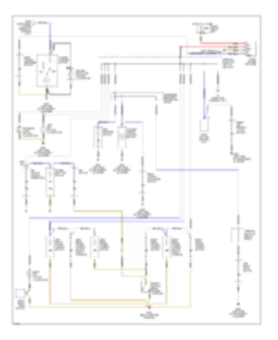
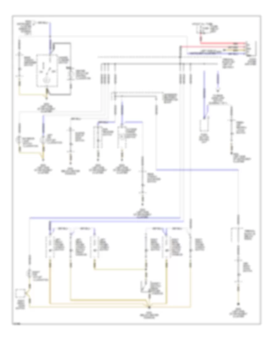
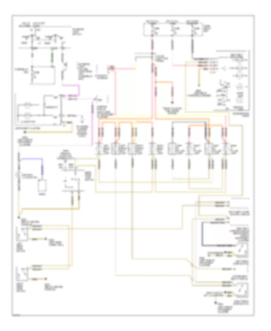
INTERIOR LIGHTS
Interior Light Wiring Diagram, Convertible (1 of 2) for Mercedes-Benz E320 1994
List of elements for Interior Light Wiring Diagram, Convertible (1 of 2) for Mercedes-Benz E320 1994:
- (right side of instrument cluster)
- 58r
- 58d
- Ashtray illumination
- Automatic antenna
- Convenience relay
- Dome lamp
- Exterior lamp failure monitoring unit (fuse/relay box)
- Exterior lamp switch
- From terminal block x6/1 (diagram 2 of 2)
- Fuse 8a
- Fuse c 16a
- Fuse/ relay box
- Fuse/relay box
- G202 (left side of instrument cluster)
- G302 (behind center console)
- G302 (below center console)
- G404 (left side of trunk, below hinge)
- Head
- Hot at all times
- Hot in off & acc
- Hot in run or start
- Illumination
- Instrument cluster
- J/c x30 (left kick panel)
- K30
- Left door switch
- Left front exit lamp
- Nca
- Off
- P30
- Park
- Power seats system
- Radio
- Rheostat
- Right air out- let illumination
- Right door switch
- Right front exit lamp
- Seat backrest locking valve
- Seat belt warning module (behind right side of instrument cluster)
- To hazard flasher switch (diagram 2 of 2)
- Trunk lamp
- Trunk lamp switch
- Warning module
Interior Light Wiring Diagram, Convertible (2 of 2) for Mercedes-Benz E320 1994
List of elements for Interior Light Wiring Diagram, Convertible (2 of 2) for Mercedes-Benz E320 1994:
- (left side of g202 instrument cluster)
- 58d
- Accessory equipment connector block
- Asr snow chain switch
- Audio power amplifier
- Block x6 (below radio)
- Center air outlet control illumination
- Exterior lamp switch illumination
- Fresh air/ recircu- lation switch
- From instrument a cluster rheostat (diagram 1 of 1)
- Fuse 8a
- Fuse/ relay box
- G202 (left side of instrument cluster)
- G302 (below center console)
- Hazard flasher switch
- Hot at all times
- Left air outlet illumination
- Left front power window switch
- Left rear power window switch
- Left rear power window switch (front console)
- Off
- Outside mirror control switch
- Power soft top switch
- Push- button control unit
- Rb switch
- Rb switch (manual operation)
- Rear window defogger switch
- Rear window sun shade switch
- Red
- Rhr release switch
- Right air outlet illumination
- Right front door switch
- Right front power window switch
- Right rear power window switch
- Right rear power window switch (front console)
- Safety switch rear power windows
- Terminal
- Terminal block x6/1 (left of ashtray)
- To dome lamp (diagram 1 of 1)
Interior Light Wiring Diagram, Coupe (1 of 2) for Mercedes-Benz E320 1994
List of elements for Interior Light Wiring Diagram, Coupe (1 of 2) for Mercedes-Benz E320 1994:
- (center of
- (right side of instrument cluster)
- 58r
- 58d
- Anti- theft alarm control unit x1
- Anti-theft system
- Ashtray illumination
- Automatic antenna
- Convenience relay
- Dome lamp
- Dome/reading lamps
- Exterior lamp failure monitoring unit (fuse/relay box)
- Exterior lamp switch
- From terminal block x6/1 (diagram 2 of 2)
- Fuse 8a
- Fuse c 16a
- Fuse/ relay box
- Fuse/relay box
- G202 (left side of instrument cluster)
- G302 (behind center console)
- G302 (below center console)
- G404 (left side of trunk, below hinge)
- G908
- Head
- Hot at all times
- Hot in off & acc
- Hot in run or start
- Illumination
- Instrument cluster
- J/c x30 (left kick panel)
- K30
- Left door switch
- Left front exit lamp
- Left sbe control module
- Nca
- Off
- P30
- Park
- Passive restraints system
- Power seats system
- Radio
- Reading lamp
- Rear dome lamp
- Rear dome lamp switch
- Rheostat
- Right air out- let illumination
- Right door switch
- Right front exit lamp
- Right front seat belt switch
- Seat belt indicators
- Seat belt warning module (behind right side of instrument cluster)
- To hazard flasher switch (diagram 2 of 2)
- Trunk lamp
- Trunk lamp switch
- Warning module
- Windshield header)
Interior Light Wiring Diagram, Coupe (2 of 2) for Mercedes-Benz E320 1994
List of elements for Interior Light Wiring Diagram, Coupe (2 of 2) for Mercedes-Benz E320 1994:
- (left side of g202 instrument cluster)
- 58d
- Accessory equipment connector block
- Asr snow chain switch
- Audio power amplifier
- Block x6 (below radio)
- Center air outlet control illumination
- Exterior lamp switch illumination
- Fresh air/ recircu- lation switch
- From instrument a cluster rheostat (diagram 1 of 1)
- Fuse 8a
- Fuse/ relay box
- G202 (left side of instrument cluster)
- G302 (below center console)
- Hazard flasher switch
- Hot at all times
- Left air outlet illumination
- Left front power window switch
- Left rear power window switch
- Left rear power window switch (front console)
- Off
- Outside mirror control switch
- Push- button control unit
- Rear window defogger switch
- Rear window sun shade switch
- Red
- Rhr release switch
- Right air outlet illumination
- Right front door switch
- Right front power window switch
- Right rear power window switch
- Right rear power window switch (front console)
- Safety switch rear power windows
- Sliding/ pop-up roof switch
- Terminal
- Terminal block x6/1 (left of ashtray)
- To rear dome lamp switch (diagram 1 of 1)
Interior Light Wiring Diagram, Sedan (1 of 2) for Mercedes-Benz E320 1994
List of elements for Interior Light Wiring Diagram, Sedan (1 of 2) for Mercedes-Benz E320 1994:
- (center of
- (right side of instrument cluster)
- 58r
- 58d
- Anti- theft alarm control unit x2
- Anti-theft system
- Ashtray illumination
- Automatic antenna
- Cf control module
- Convenience relay
- Dome lamp
- Dome/reading lamps
- Exterior lamp failure monitoring unit (fuse/relay box)
- Exterior lamp switch
- From terminal block x6/1 (diagram 2 of 2)
- Fuse 8a
- Fuse c 16a
- Fuse/ relay box
- Fuse/relay box
- G202 (left side of instrument cluster)
- G302 (behind center console)
- G302 (below center console)
- G404 (left side of trunk, below hinge)
- G908
- Head
- Hot at all times
- Hot in off & acc
- Hot in run or start
- Illumination
- Instrument cluster
- J/c x30 (left kick panel)
- K30
- Left front door switch
- Left front exit lamp
- Left rear door switch
- Left rear exit lamp
- Nca
- Off
- P30
- Park
- Power seat relay module
- Radio
- Reading lamp
- Rear dome lamp
- Rear dome lamp switch
- Rheostat
- Right air out- let illumination
- Right front door switch
- Right front exit lamp
- Right rear door switch
- Right rear exit lamp
- Seat belt indicators
- Seat belt warning module (behind right side of instrument cluster)
- To hazard flasher switch (diagram 2 of 2)
- Trunk lamp
- Trunk lamp switch
- Warning module
- Windshield header)
Interior Light Wiring Diagram, Sedan (2 of 2) for Mercedes-Benz E320 1994
List of elements for Interior Light Wiring Diagram, Sedan (2 of 2) for Mercedes-Benz E320 1994:
- (left side of g202 instrument cluster)
- 58d
- Accessory equipment connector block
- Asr snow chain switch
- Audio power amplifier
- Block x6 (below radio)
- Center air outlet control illumination
- Exterior lamp switch illumination
- Fresh air/ recircu- lation switch
- From instrument a cluster rheostat (diagram 1 of 1)
- Fuse 8a
- Fuse/ relay box
- G202 (left side of instrument cluster)
- G302 (below center console)
- Hazard flasher switch
- Hot at all times
- Left air outlet illumination
- Left front power window switch
- Left rear power window switch
- Left rear power window switch (front console)
- Off
- Outside mirror control switch
- Push- button control unit
- Rear window defogger switch
- Rear window sun shade switch
- Red
- Rhr release switch
- Right air outlet illumination
- Right front door switch
- Right front power window switch
- Right rear power window switch
- Right rear power window switch (front console)
- Safety switch rear power windows
- Sliding/ pop-up roof switch
- Terminal
- Terminal block x6/1 (left of ashtray)
- To rear dome lamp switch (diagram 1 of 1)
Interior Light Wiring Diagram, Wagon (1 of 2) for Mercedes-Benz E320 1994
List of elements for Interior Light Wiring Diagram, Wagon (1 of 2) for Mercedes-Benz E320 1994:
- (center of
- (left side of instrument cluster)
- (right side of instrument cluster)
- 58r
- 58d
- Anti-theft alarm control module
- Ashtray illumination
- Automatic antenna
- Console)
- Convenience relay
- Dome lamp
- Dome/reading lamps
- Exterior lamp failure monitoring unit (fuse/relay box)
- Exterior lamp switch
- From terminal block x6/1 (diagram 2 of 2)
- Fuse 8a
- Fuse c 16a
- Fuse/ relay box
- Fuse/relay box
- G202
- G202 (left side of instrument cluster)
- G302 (below center
- G302 (below center console)
- G404 (left rear wheel well)
- G908
- Head
- Hot at all times
- Hot in off & acc
- Hot in run or start
- Illumination
- Instrument cluster
- J/c x30 (left kick panel)
- K30
- Left c- pillar lamp
- Left d- pillar lamp
- Left front door switch
- Left front exit lamp
- Left rear door switch
- Left rear exit lamp
- Nca
- Off
- P30
- Park
- Power seat relay module
- Radio
- Reading lamp
- Rear dome lamp switch
- Rheostat
- Right air out- let illumination
- Right c- pillar lamp
- Right d- pillar lamp
- Right front door switch
- Right front exit lamp
- Right rear door switch
- Right rear exit lamp
- Seat belt indicators
- Seat belt warning module (behind right side of instrument cluster)
- To hazard flasher switch (diagram 2 of 2)
- Trunk,tailgate, fuel doors system
- Warning module
- Windshield header)
Interior Light Wiring Diagram, Wagon (2 of 2) for Mercedes-Benz E320 1994
List of elements for Interior Light Wiring Diagram, Wagon (2 of 2) for Mercedes-Benz E320 1994:
- (left side of g202 instrument cluster)
- 58d
- Accessory equipment connector block
- Asr snow chain switch
- Audio power amplifier
- Block x6 (below radio)
- Center air outlet control illumination
- Exterior lamp switch illumination
- Fresh air/ recircu- lation switch
- From instrument a cluster rheostat (diagram 1 of 1)
- Fuse 8a
- Fuse/ relay box
- G202 (left side of instrument cluster)
- G302 (below center console)
- Hazard flasher switch
- Hot at all times
- Left air outlet illumination
- Left front power window switch
- Left rear power window switch
- Left rear power window switch (front console)
- Off
- Outside mirror control switch
- Push- button control unit
- Rear window defogger switch
- Rear window sun shade switch
- Red
- Rhr release switch
- Right air outlet illumination
- Right front door switch
- Right front power window switch
- Right rear power window switch
- Right rear power window switch (front console)
- Safety switch rear power windows
- Sliding/ pop-up roof switch
- Terminal
- Terminal block x6/1 (left of ashtray)
- To rear dome lamp switch (diagram 1 of 1)
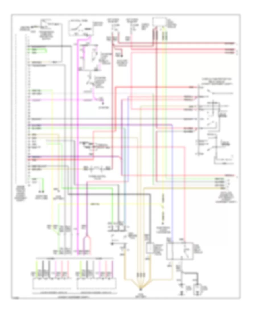
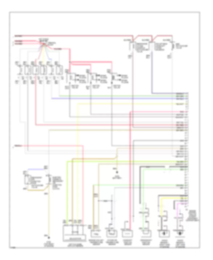
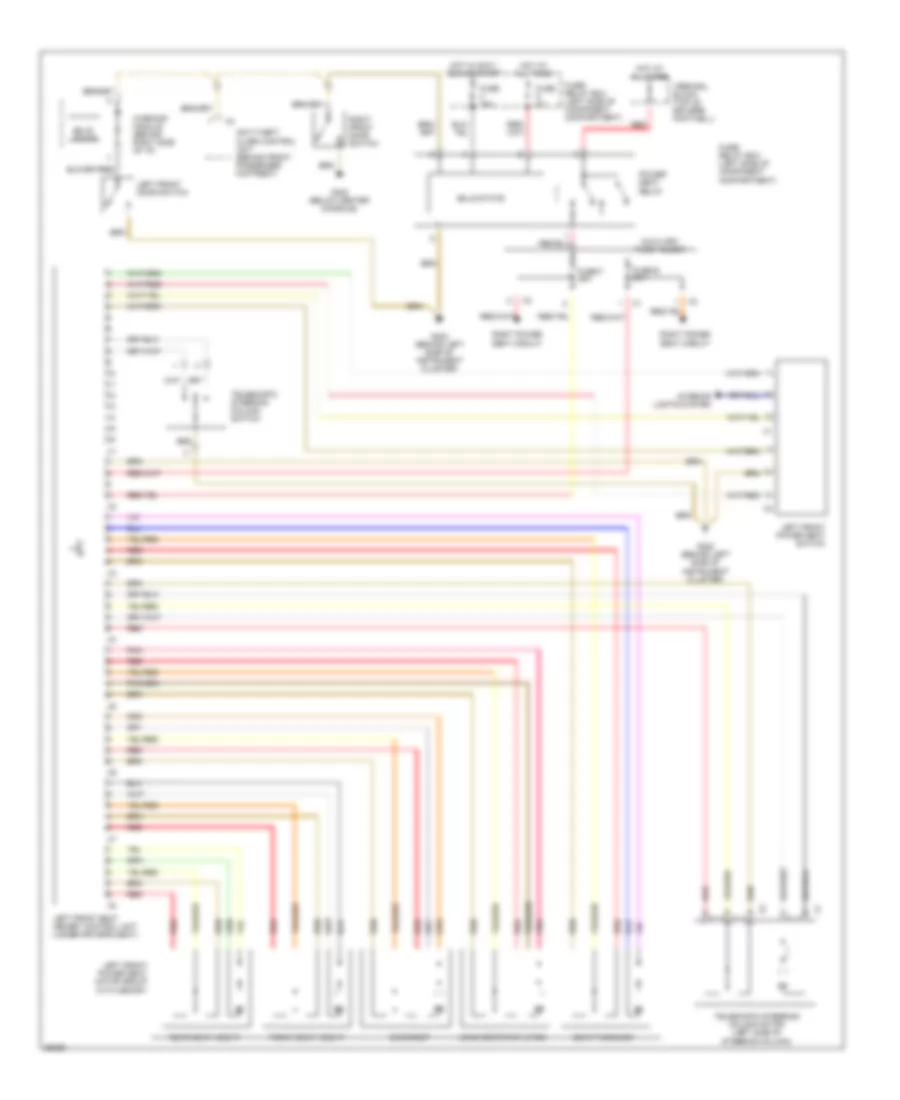
MEMORY SYSTEMS
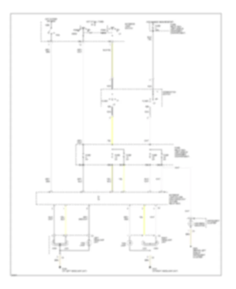
Left Front Seat & Power Steering Column Wiring Diagram for Mercedes-Benz E320 1994
List of elements for Left Front Seat & Power Steering Column Wiring Diagram for Mercedes-Benz E320 1994:
- Anti-theft alarm control unit (behind front passenger footrest)
- Auxiliary fuse holder
- Backrest
- Front seat height
- Fuse 16a
- Fuse 8a
- Fuse e 25a
- Fuse f 25a
- Fuse/ relay box (left side of component compartment)
- G202 (behind left side of instrument cluster)
- G302 (below center console)
- Head restraint up/dn
- Hot at all times
- Hot in accy, run or start
- Interior lights system
- Left front door switch
- Left front power seat motor group with memory
- Left front power seat switch
- Left front seat memory control unit (under driver's seat)
- Pnk
- Power seat relay
- Rear seat height
- Red
- Right front door switch
- Right power seat circuit
- Seat fwd/back
- Solid state
- Telescopic steering column motor (left side of steering column)
- Telescopic steering column switch
- Terminal block (top of driver's footwell)
- Warning module (behind right side of i/p)
PASSIVE RESTRAINTS
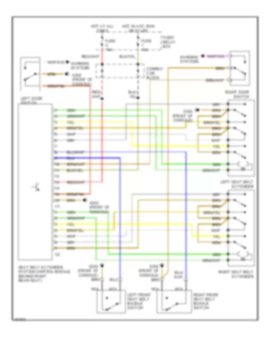
Seat Belt Extender Wiring Diagram, Convertible for Mercedes-Benz E320 1994
List of elements for Seat Belt Extender Wiring Diagram, Convertible for Mercedes-Benz E320 1994:
- Connec- tor block
- Fuse 16a
- Fuse c 16a
- Fuse/ relay box
- G302 (front of console)
- Hot at all times
- Hot in acc, run or start
- Left door switch
- Left front seat belt buckle switch
- Left seat belt extender
- Nca
- Right door switch
- Right front seat belt buckle switch
- Right seat belt extender
- Seat belt extender system control module (behind right rear seat)
- Warning systems
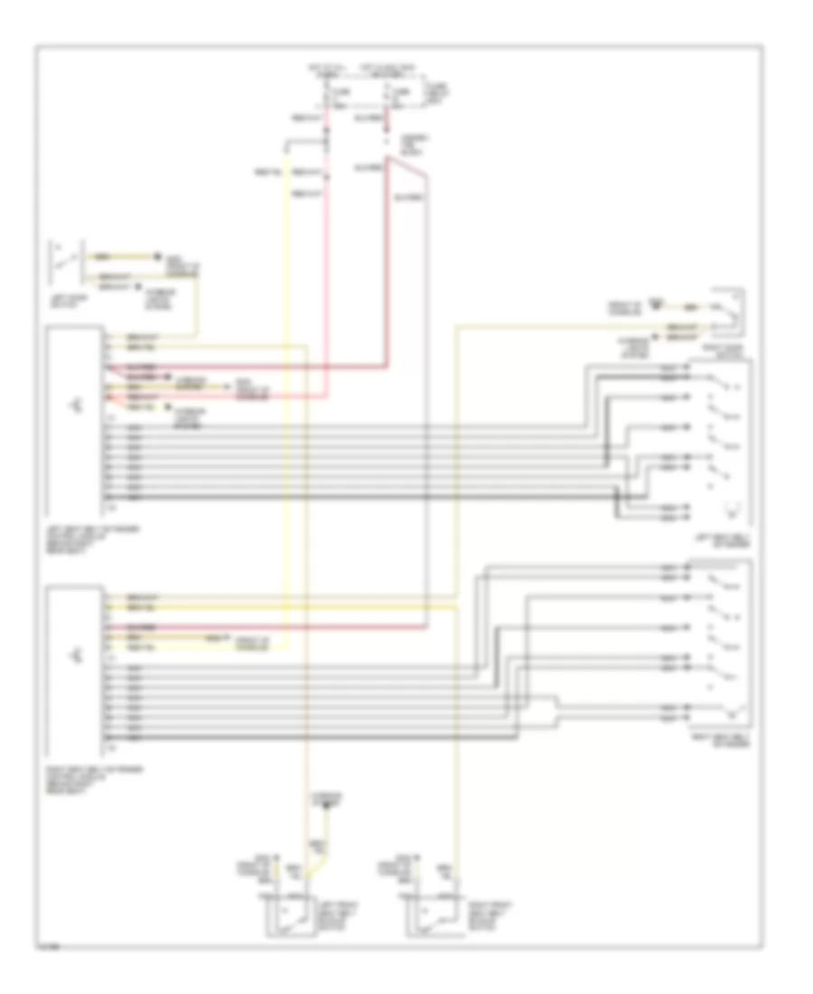
Seat Belt Extender Wiring Diagram, Coupe for Mercedes-Benz E320 1994
List of elements for Seat Belt Extender Wiring Diagram, Coupe for Mercedes-Benz E320 1994:
- (front of console)
- Connec- tor block
- Fuse b 8a
- Fuse c 16a
- Fuse/ relay box
- G302
- G302 (front of console)
- Hot at all times
- Hot in acc, run or start
- Interior lights system
- Left door switch
- Left front seat belt buckle switch
- Left seat belt extender
- Left seat belt extender control module (behind right rear seat)
- Nca
- Right door switch
- Right front seat belt buckle switch
- Right seat belt extender
- Right seat belt extender control module (behind right rear seat)
- Warning system
POWER ANTENNA
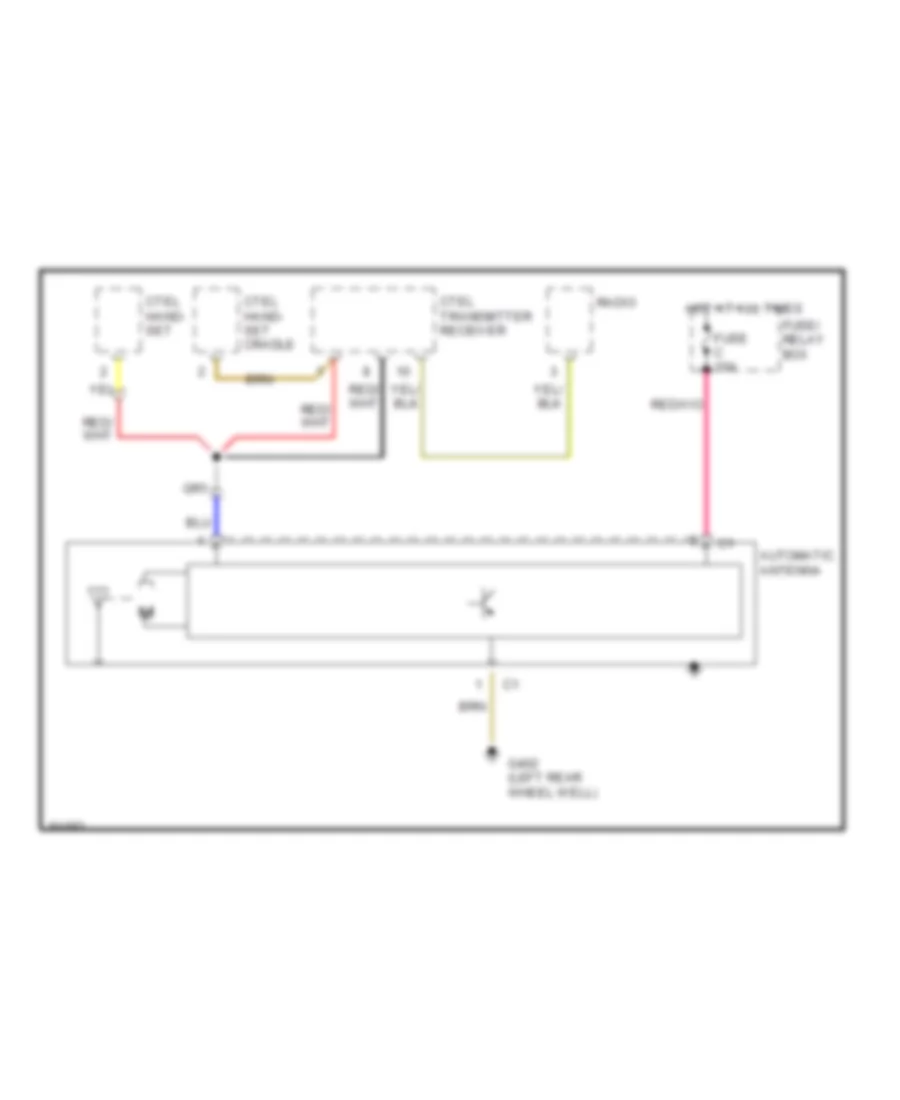
Power Antenna Wiring Diagram, with Cellular Telephone for Mercedes-Benz E320 1994
List of elements for Power Antenna Wiring Diagram, with Cellular Telephone for Mercedes-Benz E320 1994:
- Automatic antenna
- Ctel hand- set
- Ctel hand- set cradle
- Ctel transmitter receiver
- Fuse c 16a
- Fuse/ relay box
- G402 (left rear wheel well)
- Hot at all times
- Radio
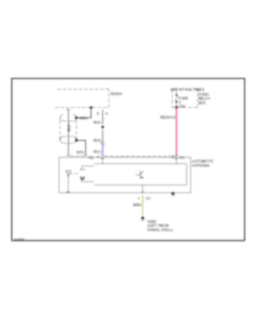
Power Antenna Wiring Diagram, without Cellular Telephone for Mercedes-Benz E320 1994
List of elements for Power Antenna Wiring Diagram, without Cellular Telephone for Mercedes-Benz E320 1994:
- Automatic antenna
- Fuse c 16a
- Fuse/ relay box
- G402 (left rear wheel well)
- Hot at all times
- Nca
- Radio
POWER DISTRIBUTION
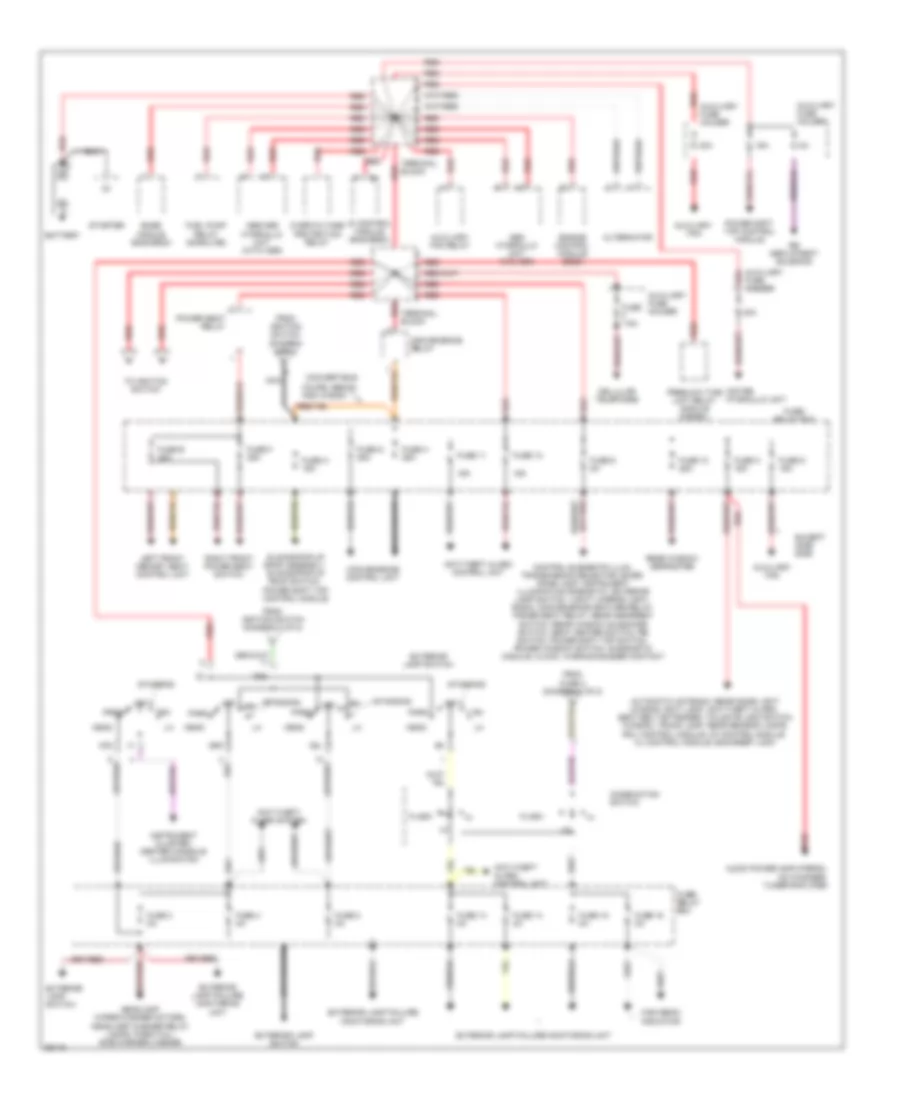
Power Distribution Wiring Diagram (1 of 2) for Mercedes-Benz E320 1994
List of elements for Power Distribution Wiring Diagram (1 of 2) for Mercedes-Benz E320 1994:
- 16a
- 30a
- 58l
- 58r
- Abs hydraulic unit (w/o asr)
- Abs/asr hydraulic unit (with asr)
- Alternator
- Anti-theft alarm control unit
- Anti-theft alarm control unit
- Anti-theft alarm system
- Audio power amplifier(s), cd changer, tuner/amplifier
- Automatic antenna, rear dome light (wagon), exit lamp, anti-theft alarm, seat belt extender, tailgate lock switch (wagon), trunk lamp, rear reading lamps, ircl control module, cf control module, cl control module, backrest lock
- Auxiliary fan
- Auxiliary fan
- Auxiliary fan relay
- Auxiliary fuse holder
- Base module (e420/e500)
- Battery
- Cellular telephone
- Combination switch
- Control elements illum, transmission selector lever, dome lamp, instrument illumination rheostat, exterior lamp switch, vanity mirror light, radio, convenience feature relay, power seat relay, rear headrest switch, rear window sunshade switch, seat heater switch, rb switch, power soft top switch, power window switch, diagnostic module, clock, warning buzzer contact
- Convenience control unit
- Convenience relay
- Convertible
- Coupe, sedan and wagon
- Cst/rb hydraulic unit
- Di control module (e420/e500)
- Engine control module (e320)
- Except 400e/ 500e
- Exterior lamp failure monitoring unit
- Exterior lamp switch
- Flash
- From fuse 2 (diagram 2 of 2)
- From ignition switch (diagram 2 of 2)
- Fuel pump relay (gasoline)
- Fuse 10 25a
- Fuse 11
- Fuse 12
- Fuse 13 8a
- Fuse 14 8a
- Fuse 15 8a
- Fuse 16 8a
- Fuse 3 8a
- Fuse 4 8a
- Fuse 8 8a
- Fuse 9 8a
- Fuse a 16a
- Fuse c 16a
- Fuse d 16a
- Fuse e 25a
- Fuse f 25a
- Fuse f 7.5a
- Fuse g 25a
- Fuse h 25a
- Fuse/ relay box
- Head
- Headlamp wiper/washer motors, headlamp washer relay lamps: park/tail/ side marker/license
- High beam indicator
- Instrument cluster/ center console illumination
- K30
- Left front memory seat control unit
- Nca
- Off
- Overvoltage protection relay
- P30
- Park
- Power seat relay
- Power soft top control module
- Preglow time limit relay module (diesel)
- Rb deployment solenoid
- Rear window defroster
- Red
- Right front power seat switch
- Sliding/pop-up roof assembly, sliding/pop-up roof switch, power soft top control module
- Standing
- Starter
- Terminal block
- To ignition switch
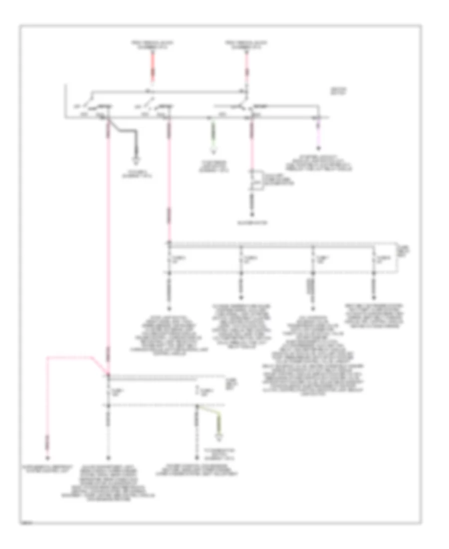
Power Distribution Wiring Diagram (2 of 2) for Mercedes-Benz E320 1994
List of elements for Power Distribution Wiring Diagram (2 of 2) for Mercedes-Benz E320 1994:
- 15r
- 15x
- 30a
- A/c, kickdown solenoid valve, transmission mode valve, data link connector, throttle valve actual valve potentiometer, electromagnetic clutch, a/c compressor, auxiliary fan relay, o2s heater relay module, monovalve, duovalve, auxiliary coolant pump, fresh/recirc air flap switchover valve, purge control valve, upshift delay solenoid valve, heated windshield washer nozzle, kickdown cut-out relay module, hfm-sfi control module, egr switchover valve 2, resonance intake manifold switchover valve, air pump switchover valve, adjustable camshaft timing solenoid, electromagnetic air pump clutch, control/function indicator lamp, backup lamp switch
- Acc
- Auxiliary fuse holder, blower motor
- Blower motor
- From terminal block (diagram 1 of 2)
- Fuse 1 16a
- Fuse 2 16a
- Fuse 5 8a
- Fuse 6 8a
- Fuse 7 16a
- Fuse b 8a
- Fuse/ relay box
- Glove compartment light, rear window wiper/washer system, radio, rear window defroster, rear window sun shade motor, sliding/pop-up roof, folding rear head restraints, central locking system, orthopedic backrest, cigar lighter, sbe control module, convenience feature
- Ignition switch
- Nca
- Off
- Outside temperature gauge, fanfare horns, auxiliary turn signal lamp, starter switch, instrument cluster, abs control/function lamps, twc malfunction control module, pec control module, roll bar, over- voltage protection, ignition coils, preglow time limit relay module
- Pnk/red
- Power windows, convenience feature, headlamp wiper/washer, wiper washer system, seat adjustment
- Red
- Run
- Seat belt extender system, anti-theft alarm system, automatic dimming rear view mirror, seat belt warning module, ircl control module, heated outside mirrors
- Start
- Starter lock-out/ back-up lamp switch (a/t), fuel pump relay & starter (m/t), preglow time limit relay module
- Stop lamp switch, front dome lamp, tach, speed sensor, instrument cluster, exterior lamp failure monitoring module, cruise control, warning module, rb control lamp, rb switch, power soft top, seat belt warning module, daytime running lamp control module
- To combination switch (diagram 1 of 2)
- To exterior lamp switch (diagram 1 of 2)
- To fuse a (diagram 1 of 2)
POWER DOOR LOCKS
Power Door Lock Wiring Diagram for Mercedes-Benz E320 1994
List of elements for Power Door Lock Wiring Diagram for Mercedes-Benz E320 1994:
- 2-door
- 4-door & wagon
- Accessory equipment connector block
- Door lock
- Electrical center (left side of component compartment)
- Exc. wagon
- Fuse a 8a
- Fuse c 16a
- G302 (behind lower front of console)
- Gas cap actuator
- Gas cap flap
- Hot at all times
- Hot in run or start
- Left front door actuator
- Left rear door actuator
- Lid lock
- Lock
- Power seats (seat regulating valve)
- Right front door actuator
- Right rear door actuator
- Solid state
- Trunk/ tailgate lid lock actuator
- Un- lock
- Vacuum actuator
- Wagon
- Warning buzzer switch (dash panel, right of steering column)
POWER MIRRORS
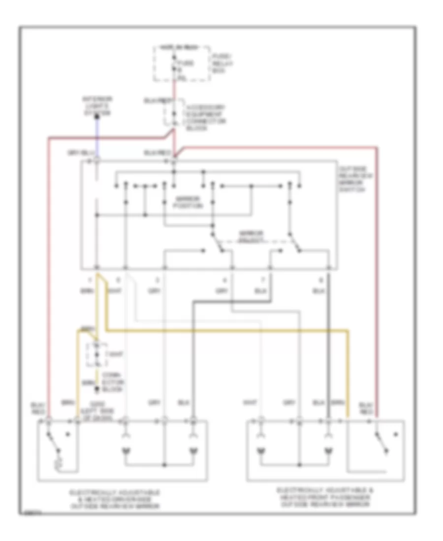
Power Mirror Wiring Diagram for Mercedes-Benz E320 1994
List of elements for Power Mirror Wiring Diagram for Mercedes-Benz E320 1994:
- Accessory equipment connector block
- Block
- Electrically adjustable & heated driver-side outside rearview mirror
- Electrically adjustable & heated front passenger outside rearview mirror
- Fuse b 8a
- Fuse/ relay box
- G202 (left side of dash)
- Hot in run
- Interior lights system
- Mirror position
- Mirror select
- Outside rearview mirror switch
POWER SEATS
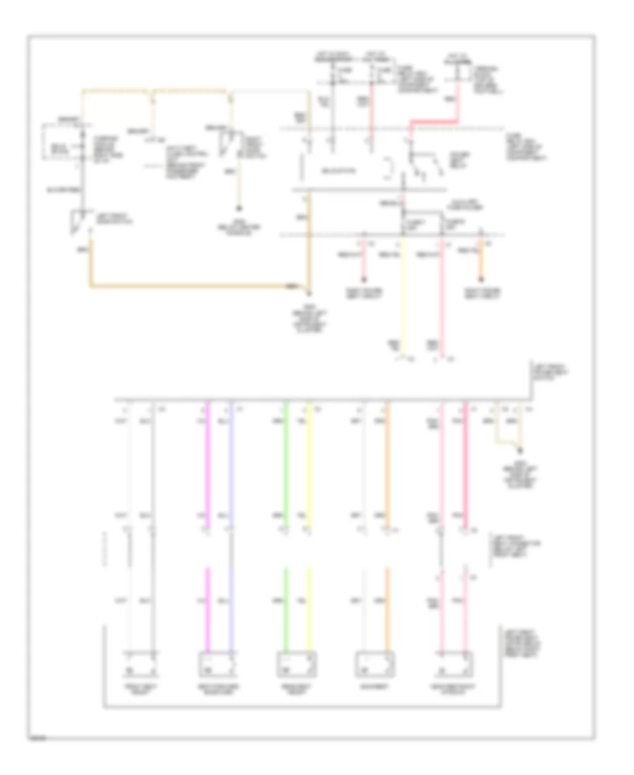
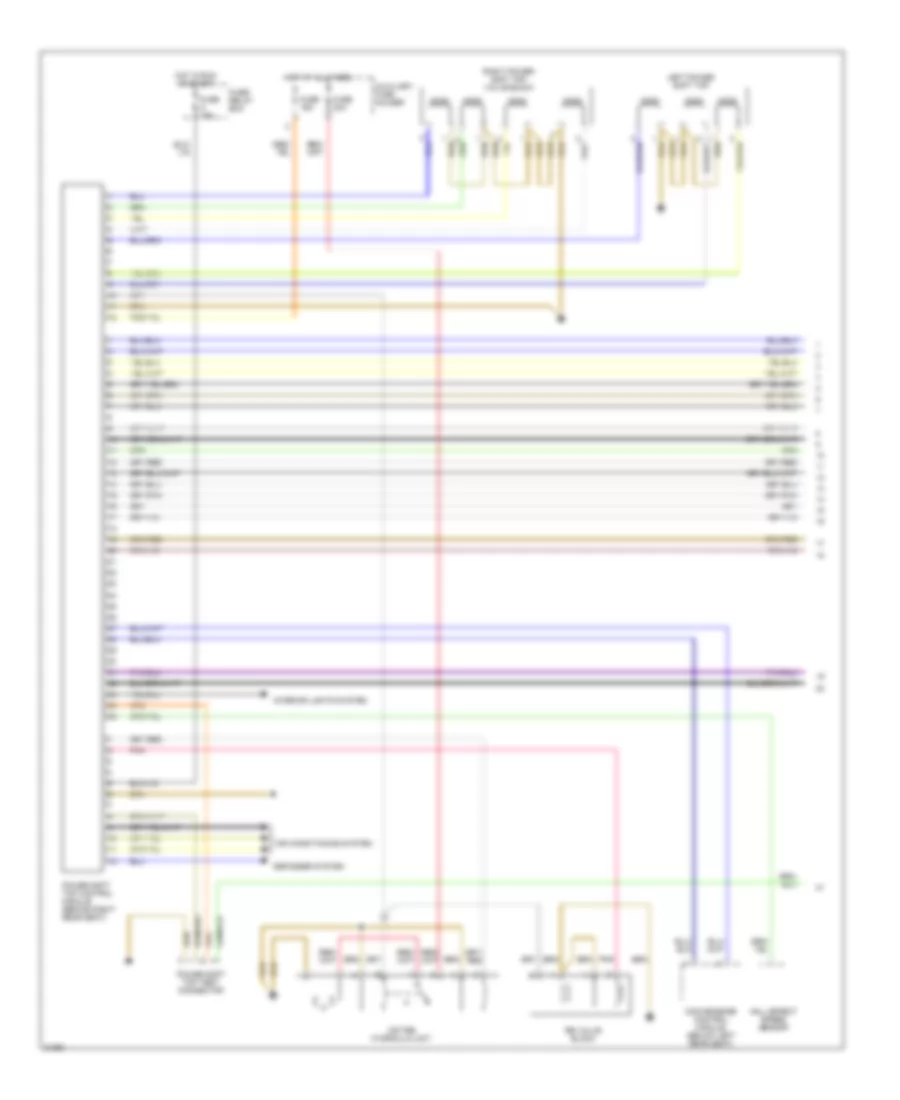
Driver Power Seat Wiring Diagram for Mercedes-Benz E320 1994
List of elements for Driver Power Seat Wiring Diagram for Mercedes-Benz E320 1994:
- Anti-theft alarm control unit (behind front passenger footrest)
- Auxiliary fuse holder
- Backrest
- Front seat height
- Fuse 16a
- Fuse 8a
- Fuse e 25a
- Fuse f 25a
- Fuse/ relay box (left side of component compartment)
- G202 (behind left side of instrument cluster)
- G302 (below center console)
- Head restraint up/down
- Hot at all times
- Hot in accy, run or start
- Left front door switch
- Left front power seat motor group (below right front seat)
- Left front power seat switch
- Left front seat connector (below left front seat)
- Pnk
- Power seat relay
- Rear seat height
- Red
- Right front door switch
- Right power seat circuit
- Seat forward/ backward
- Solid state
- Terminal block (top of driver's footwell)
- Warning module (behind right side of i/p)
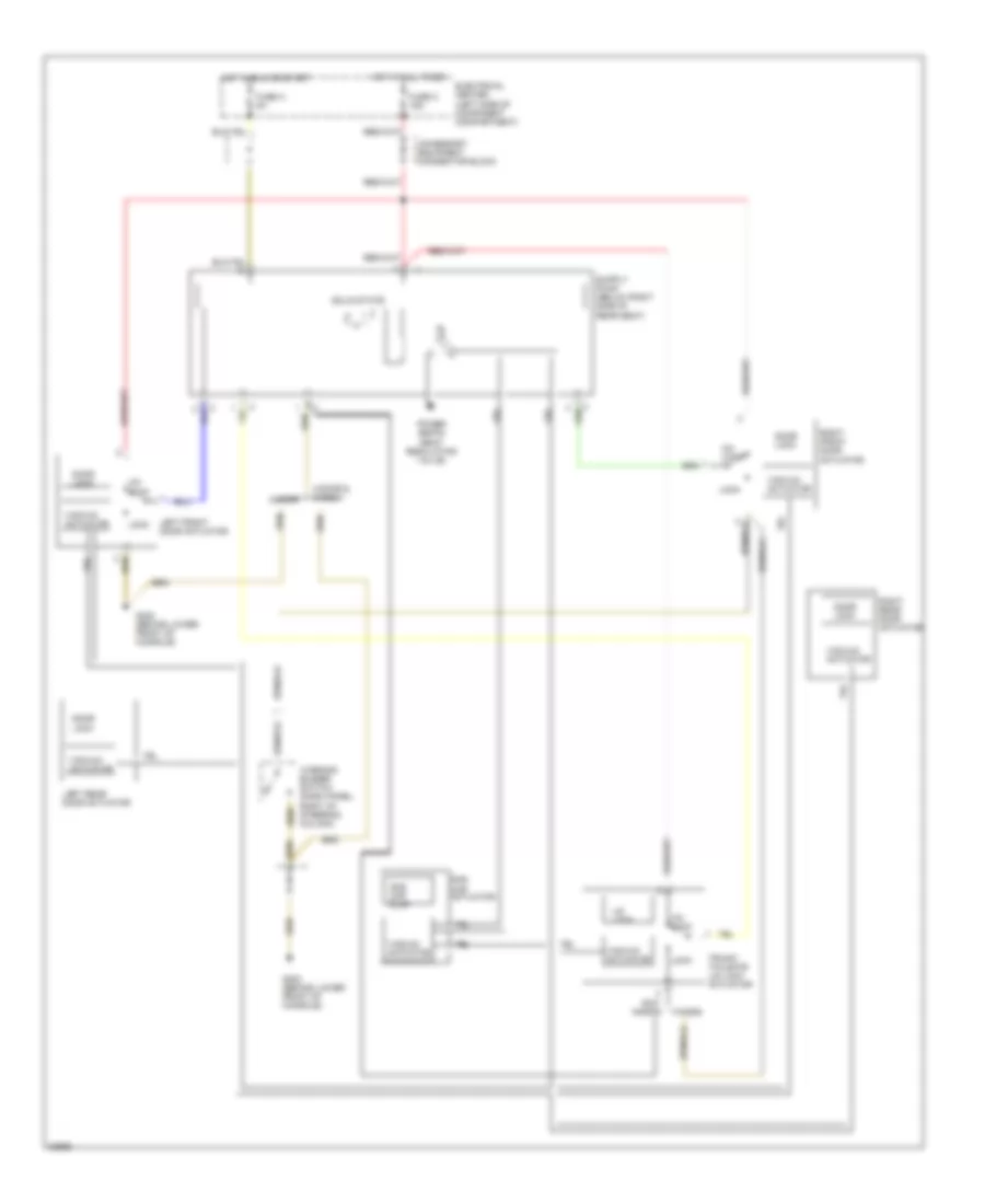
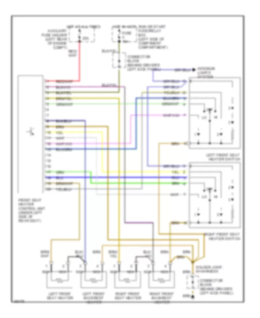
Heater Wiring Diagram for Mercedes-Benz E320 1994
List of elements for Heater Wiring Diagram for Mercedes-Benz E320 1994:
- 25a
- Auxiliary fuse holder (left rear of engine compt)
- Connector block (behind driver's left kick panel)
- Front seat heater control unit (under left side of rear seat)
- Fuse a 16a
- Hot at all times
- Hot in accy, run or start fuse/relay box (left side of component compartment)
- Interior lights system
- Left front backrest heater
- Left front seat heater
- Left front seat heater switch
- Nca
- Off
- Right front backrest heater
- Right front seat heater
- Right front seat heater switch
- Solder joint, in harness
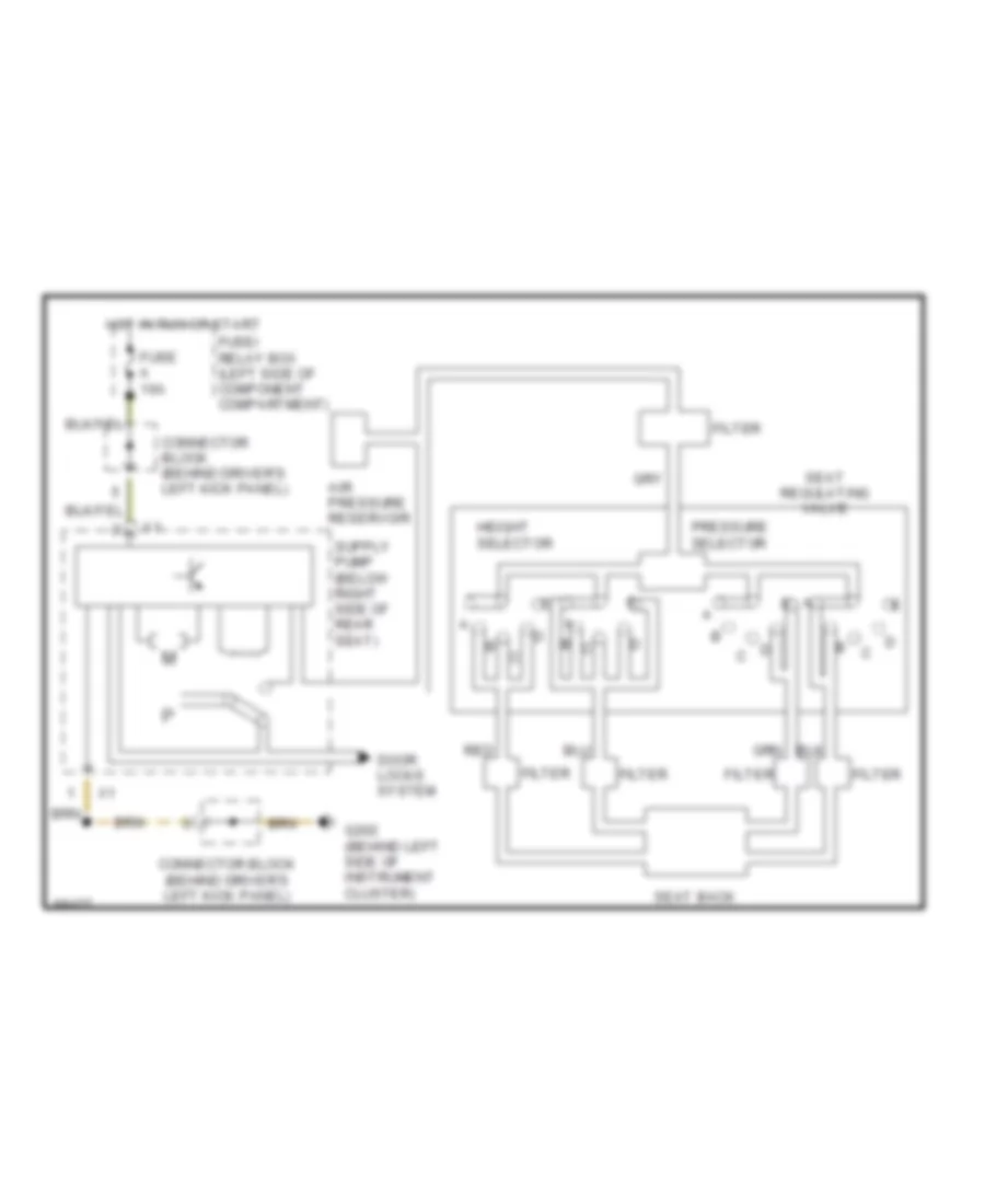
Orthopedic Seats for Mercedes-Benz E320 1994
List of elements for Orthopedic Seats for Mercedes-Benz E320 1994:
- Air pressure reservoir
- Connector block (behind driver's left kick panel)
- Door locks system
- Filter
- Fuse a 16a
- Fuse/ relay box (left side of component compartment)
- G202 (behind left side of instrument cluster)
- Height selector
- Hot in run or start
- Pressure selector
- Red
- Seat back
- Seat regulating valve
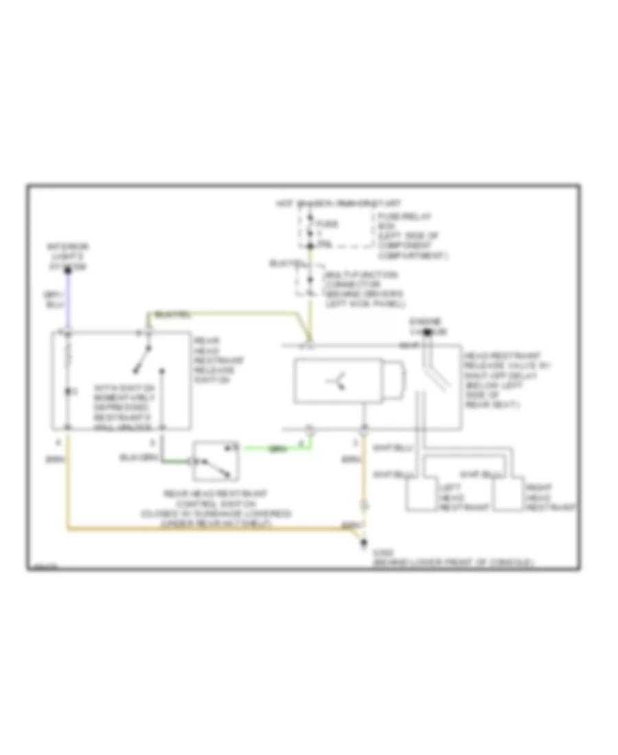
Rear Head Restraint Wiring Diagram for Mercedes-Benz E320 1994
List of elements for Rear Head Restraint Wiring Diagram for Mercedes-Benz E320 1994:
- Engine vacuum
- Fuse 16a
- Fuse/relay box (left side of component compartment)
- G302 (behind lower front of console)
- Head restraint release valve w/ shut-off delay (below left side of rear seat)
- Hot in accy, run or start
- Interior lights system
- Left head restraint
- Multi-function connector (behind driver's left kick panel)
- Rear head restraint control switch (closed w/ sunshade lowered) (under rear hatshelf)
- Rear head restraint release switch
- Right head restraint
- With switch momentarily depressed, restraints will unlock
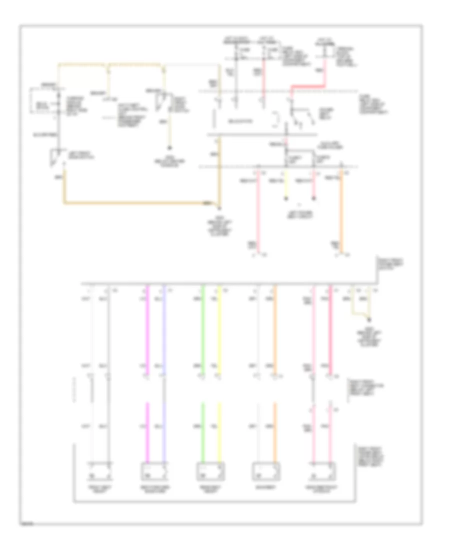
Right Seat Wiring Diagram for Mercedes-Benz E320 1994
List of elements for Right Seat Wiring Diagram for Mercedes-Benz E320 1994:
- Anti-theft alarm control unit (behind front passenger footrest)
- Auxiliary fuse holder
- Backrest
- Front seat height
- Fuse 16a
- Fuse 8a
- Fuse e 25a
- Fuse f 25a
- Fuse/ relay box (left side of component compartment)
- G202 (behind left side of instrument cluster)
- G302 (below center console)
- Head restraint up/down
- Hot at all times
- Hot in accy, run or start
- Left front door switch
- Left power seat circuit
- Pnk
- Power seat relay
- Rear seat height
- Red
- Right front door switch
- Right front power seat motor group (below right front seat)
- Right front power seat switch
- Right front seat connector (below left front seat)
- Seat forward/ backward
- Solid state
- Terminal block (top of driver's footwell)
- Warning module (behind right side of i/p)
POWER TOP/SUNROOF
Convertible Top Wiring Diagram (1 of 2) for Mercedes-Benz E320 1994
List of elements for Convertible Top Wiring Diagram (1 of 2) for Mercedes-Benz E320 1994:
- Air conditioning system
- Auxiliary fuse holder
- Convenience control module (below left rear seat)
- Cst/rb hydraulic unit
- Defogger system
- Fuse 16a
- Fuse 30a
- Fuse a 16a
- Fuse/ relay box
- Hall effect speed sensor
- Hot at all times
- Hot in run or start
- Interior lights system
- Left power soft top
- Pnk
- Power soft top control module (behind right rear seat)
- Power soft top test connector
- Rb valve block
- Right power soft top valve block
Convertible Top Wiring Diagram (2 of 2) for Mercedes-Benz E320 1994
List of elements for Convertible Top Wiring Diagram (2 of 2) for Mercedes-Benz E320 1994:
- Auxiliary fuse holder
- Bk/bn/wt
- Center console rear power windows safety switch
- Center console roll bar malfunction indicator lamp
- Data link connector
- Fuse 8a
- Fuse/ relay box
- G202 (left side of dash)
- G302 (below center console)
- Gy/gn/wt
- Gy/yl/gn
- Hot at all times
- Hot in run or start
- Interior lights system
- J/c (below left rear seat)
- Left front soft top locked switch
- Left rear roll bar axle switch
- Nca
- Pnk
- Power soft top switch
- Rb crash deployment control module (below passenger's seat)
- Rb deployment solenoid
- Rb extended switch
- Rb retracted switch
- Rb switch
- Rear center console rb switch
- Right front soft top locked switch
- Right rear roll bar axle switch
- Soft top closed switch
- Soft top compartment cover switch
- Soft top compartment open switch
- Soft top fabric bow down switch
- Soft top open switch
- Starting/charging system
- Top fabric bow locked switch
- Top fabric bow raised switch
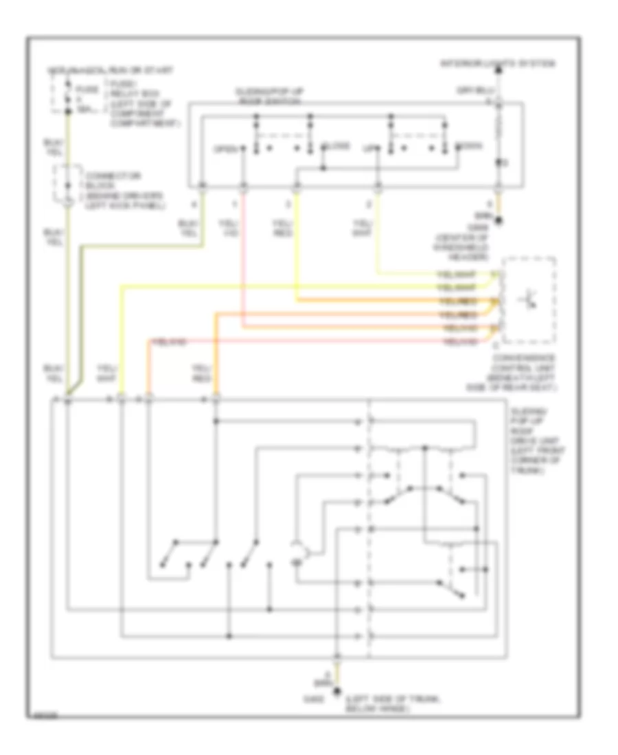
Sunroof Wiring Diagram for Mercedes-Benz E320 1994
List of elements for Sunroof Wiring Diagram for Mercedes-Benz E320 1994:
- (left side of trunk, below hinge)
- Close
- Connector block (behind driver's left kick panel)
- Convenience control unit (beneath left side of rear seat)
- Down
- Fuse a 16a
- Fuse/ relay box (left side of component compartment)
- G402
- G908 (center of windshield header)
- Hot in accy, run or start
- Interior lights system
- Open
- Sliding/ pop-up roof drive unit (left front corner of trunk)
- Sliding/pop-up roof switch
POWER WINDOWS
Power Window Wiring Diagram for Mercedes-Benz E320 1994
List of elements for Power Window Wiring Diagram for Mercedes-Benz E320 1994:
- (behind lower
- Accessory equipment connector block
- Auto dn
- Battery
- Convenience control unit (beneath left side of rear seat)
- Convenience relay (rear of fuse box)
- Front of console)
- Fuse 1 8a
- Fuse 2 16a
- Fuse 9 8a
- Fuse a 16a
- Fuse c 16a
- Fuse g 25a
- Fuse h 25a
- Fuse/relay box (left side of component compartment)
- G101 (right shock tower)
- G302
- G302 (behind lower front of console)
- Hot at all times
- Hot in acc, run and start
- Hot in run or start
- Interior lights system
- Left front door switch
- Left front power window motor
- Left front power window switch
- Left rear power window motor
- Left rear power window switch (console)
- Left rear power window switch (door)
- Red
- Right front power window motor
- Right front power window switch
- Right rear power window motor
- Right rear power window switch (console)
- Right rear power window switch (door)
- Roll bar switch (covt. only)
- Safety switch, rear power windows
- Solid state
- Terminal block (center of dashboard)
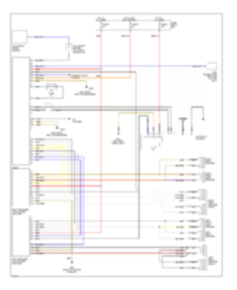
RADIO
Radio Wiring Diagrams, High Performance Audio for Mercedes-Benz E320 1994
List of elements for Radio Wiring Diagrams, High Performance Audio for Mercedes-Benz E320 1994:
- (left front seat crossmember)
- 1-8
- 10a
- Antenna
- Automatic antenna
- Cd changer
- Ctel transmitter/ receiver (w/ ctel only)
- Fuse 3 8a
- Fuse 9 8a
- Fuse c 16a
- Fuse f1
- Fuse/ relay box
- G300
- G302 (front of center console)
- G404 (left rear wheel well)
- Hall-effect sensor multipoint connector
- Hall-effect speed sensor
- Hot at all times
- Hot in acc, run or start
- Interior lights system
- Left front door speaker
- Left front speaker
- Left rear speaker group
- Left speakers audio power amplifier
- Nca
- Nca nca
- Radio
- Red
- Right front door speaker
- Right front speaker
- Right rear speaker group
- Right speakers audio power amplifier
Radio Wiring Diagrams, Standard Audio for Mercedes-Benz E320 1994
List of elements for Radio Wiring Diagrams, Standard Audio for Mercedes-Benz E320 1994:
- (left front seat crossmember)
- 1-8
- 10a
- Antenna
- Automatic antenna
- Cd changer
- Console)
- Ctel transmitter/ receiver (w/ ctel only)
- Fuse 3 8a
- Fuse 9 8a
- Fuse c 16a
- Fuse f1
- Fuse/ relay box
- G300
- G302 (front of center
- G404 (left rear wheel well)
- Hall-effect sensor multipoint connector
- Hall-effect speed sensor
- Hot at all times
- Hot in acc, run or start
- Interior lights system
- Left front door speaker
- Left front speaker
- Left rear speaker
- Left/right audio power amplifier
- Nca
- Radio
- Red
- Right front door speaker
- Right front speaker
- Right rear speaker
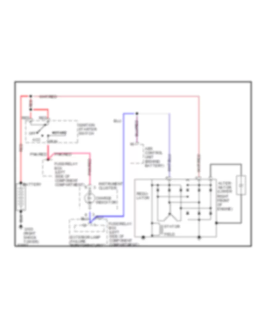
STARTING/CHARGING
Charging Wiring Diagram for Mercedes-Benz E320 1994
List of elements for Charging Wiring Diagram for Mercedes-Benz E320 1994:
- Abs control unit (behind battery)
- Acc
- Alter- nator (lower
- Battery
- Charge indicator
- Exterior lamp failure monitoring unit
- Field
- Fuse/relay box (left side of component compartment)
- G103 (right shock tower)
- Ignition starter switch
- Instrument cluster
- Off
- Pnk/red
- Red
- Regu- lator
- Right front of engine)
- Run
- Start
- Stator
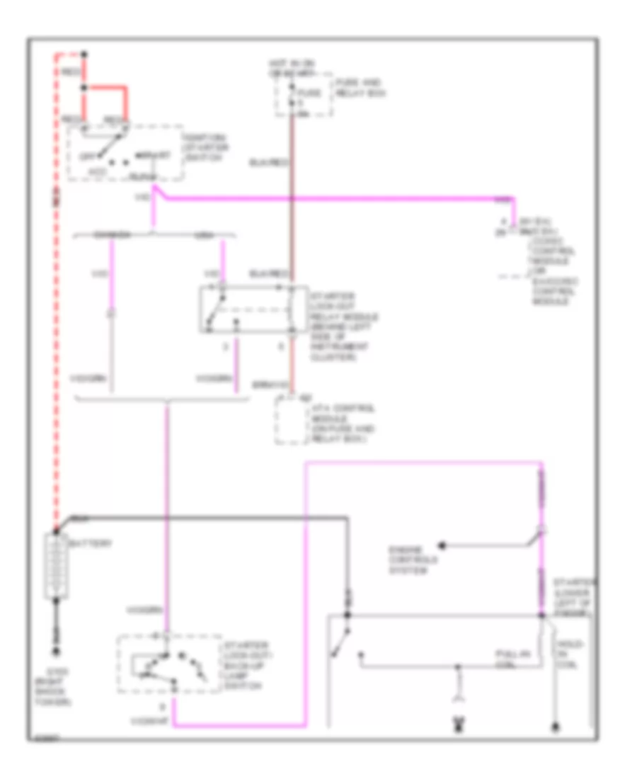
Starting Wiring Diagram for Mercedes-Benz E320 1994
List of elements for Starting Wiring Diagram for Mercedes-Benz E320 1994:
- (right shock tower)
- (w/ ea) (w/o ea)
- Acc
- Ata control module (on fuse and relay box)
- Battery
- Canada
- Cc/isc control module or ea/cc/isc control module
- Engine controls system
- Fuse 8a
- Fuse and relay box
- G103
- Hold- in coil
- Hot in on or start
- Ignition/ starter switch
- Off
- Pull-in coil
- Red
- Run
- Start
- Starter (lower left of engine)
- Starter lock-out relay module (behind left side of instrument cluster)
- Starter lock-out/ back-up lamp switch
- Usa
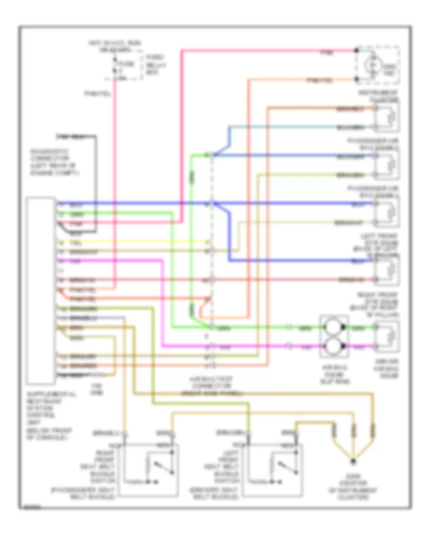
SUPPLEMENTAL RESTRAINTS
Supplemental Restraint Wiring Diagram for Mercedes-Benz E320 1994
List of elements for Supplemental Restraint Wiring Diagram for Mercedes-Benz E320 1994:
- (below front of console)
- (driver's seat belt buckle)
- (passenger's seat belt buckle)
- Air bag squib slip ring
- Air bag test connector (right kick panel)
- Diagnostic connector (left rear of engine compt)
- Driver air bag squib
- Fuse 8a
- Fuse/
- G206 (center of instrument cluster)
- Hot in acc, run or start
- Instrument cluster
- Left front etr squib (base of left "b" pillar)
- Left front seat belt buckle switch
- Nca
- Ohm
- Passenger air bag squib 1
- Passenger air bag squib 2
- Pnk
- Relay box
- Right front etr squib (base of right "b" pillar)
- Right front seat belt buckle switch
- Srs ind
TRUNK, TAILGATE, FUEL DOOR
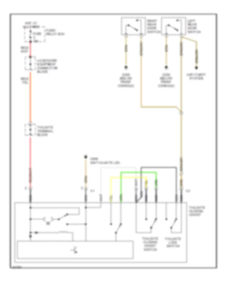
Door Closing Assist Wiring Diagram, Wagon for Mercedes-Benz E320 1994
List of elements for Door Closing Assist Wiring Diagram, Wagon for Mercedes-Benz E320 1994:
- Accessory equipment connector block
- Anti-theft system
- Fuse c 16a
- Fuse/ relay box
- G302 (below front console)
- G406 (on tailgate lid)
- Hot at all times
- Left rear door switch
- Nca
- Right rear door switch
- Tailgate closing assist
- Tailgate closing assist switch
- Tailgate lock switch
- Tailgate terminal block
WARNING SYSTEMS
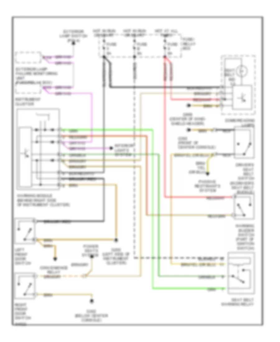
Warning System Wiring Diagrams, Coupe & Convertible for Mercedes-Benz E320 1994
List of elements for Warning System Wiring Diagrams, Coupe & Convertible for Mercedes-Benz E320 1994:
- C13
- Convenience relay
- Dome/reading lamps
- Driver's seat belt switch (in driver's seat belt buckle)
- Exterior lamp failure monitoring unit (fuse/relay box)
- Exterior lamp switch (pin 4)
- Fuse 8a
- Fuse b 8a
- Fuse/ relay box
- G202 (left side of instrument cluster)
- G302 (below center console)
- G302 (front of center console)
- G908 (center of wind- shield header)
- Hot at all times
- Hot in run or start
- Instrument cluster
- Interior lights system
- Left front door switch
- Nca
- Passive restraints system
- Power seats system
- Right front door switch
- Seat belt ind x3
- Seat belt warning relay
- Warning buzzer switch (part of ignition switch)
- Warning module (behind right side of instrument cluster)
- X1/4
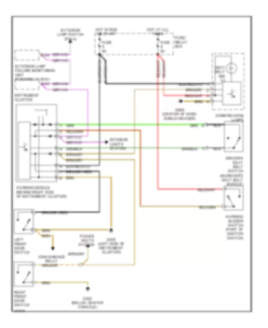
Warning System Wiring Diagrams, Sedan for Mercedes-Benz E320 1994
List of elements for Warning System Wiring Diagrams, Sedan for Mercedes-Benz E320 1994:
- C13
- Convenience relay
- Dome/reading lamps
- Driver's seat belt switch (in driver's seat belt buckle)
- Exterior lamp failure monitoring unit (fuse/relay box)
- Exterior lamp switch (pin 4)
- Fuse 8a
- Fuse/ relay box
- G202 (left side of instrument cluster)
- G302 (below center console)
- G908 (center of wind- shield header)
- Hot at all times
- Hot in run or start
- Instrument cluster
- Interior lights system
- Left front door switch
- Nca
- Power seats system
- Right front door switch
- Seat belt ind x3
- Warning buzzer switch (part of ignition switch)
- Warning module (behind right side of instrument cluster)
- X1/4
Warning System Wiring Diagrams, Wagon for Mercedes-Benz E320 1994
List of elements for Warning System Wiring Diagrams, Wagon for Mercedes-Benz E320 1994:
- C13
- Convenience relay
- Dome/reading lamps
- Driver's seat belt switch (in driver's seat belt buckle)
- Exterior lamp failure monitoring unit (fuse/relay box)
- Exterior lamp switch (pin 4)
- Fuse 8a
- Fuse/ relay box
- G202 (left side of instrument cluster)
- G302 (below center console)
- G908 (center of wind- shield header)
- Hot at all times
- Hot in run or start
- Instrument cluster
- Interior lights system
- Left front door switch
- Nca
- Power seats system
- Right front door switch
- Seat belt ind x3
- Warning buzzer switch (part of ignition switch)
- Warning module (behind right side of instrument cluster)
- X1/4
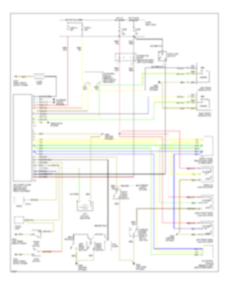
WIPER/WASHER
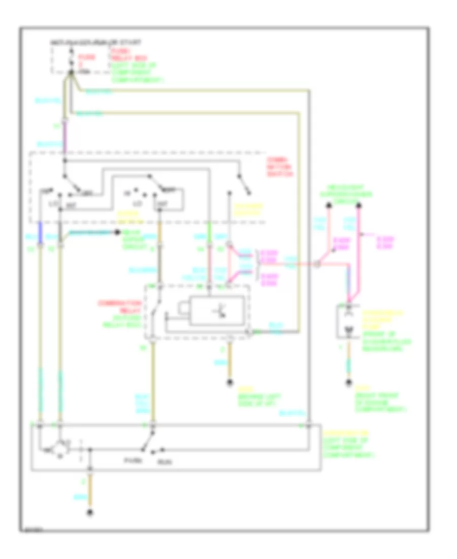
Front Washer/Wiper Wiring Diagram for Mercedes-Benz E320 1994
List of elements for Front Washer/Wiper Wiring Diagram for Mercedes-Benz E320 1994:
- Combi- nation switch
- Combination relay (in fuse/ relay box)
- E320/ e300
- E420/ e500
- Fuse 16a
- Fuse/ relay box (left side of component compartment)
- G101 (right front of engine compartment)
- G202 (behind left side of i/p)
- Headlight wiper/washer circuit
- Hot in accy,run or start
- Int
- Off
- Park
- Rear wiper circuit
- Run
- Washer switch
- Windshield washer pump (front of washer fluid reservoir)
- Wiper motor (left side of component compartment)
- Wiper switch
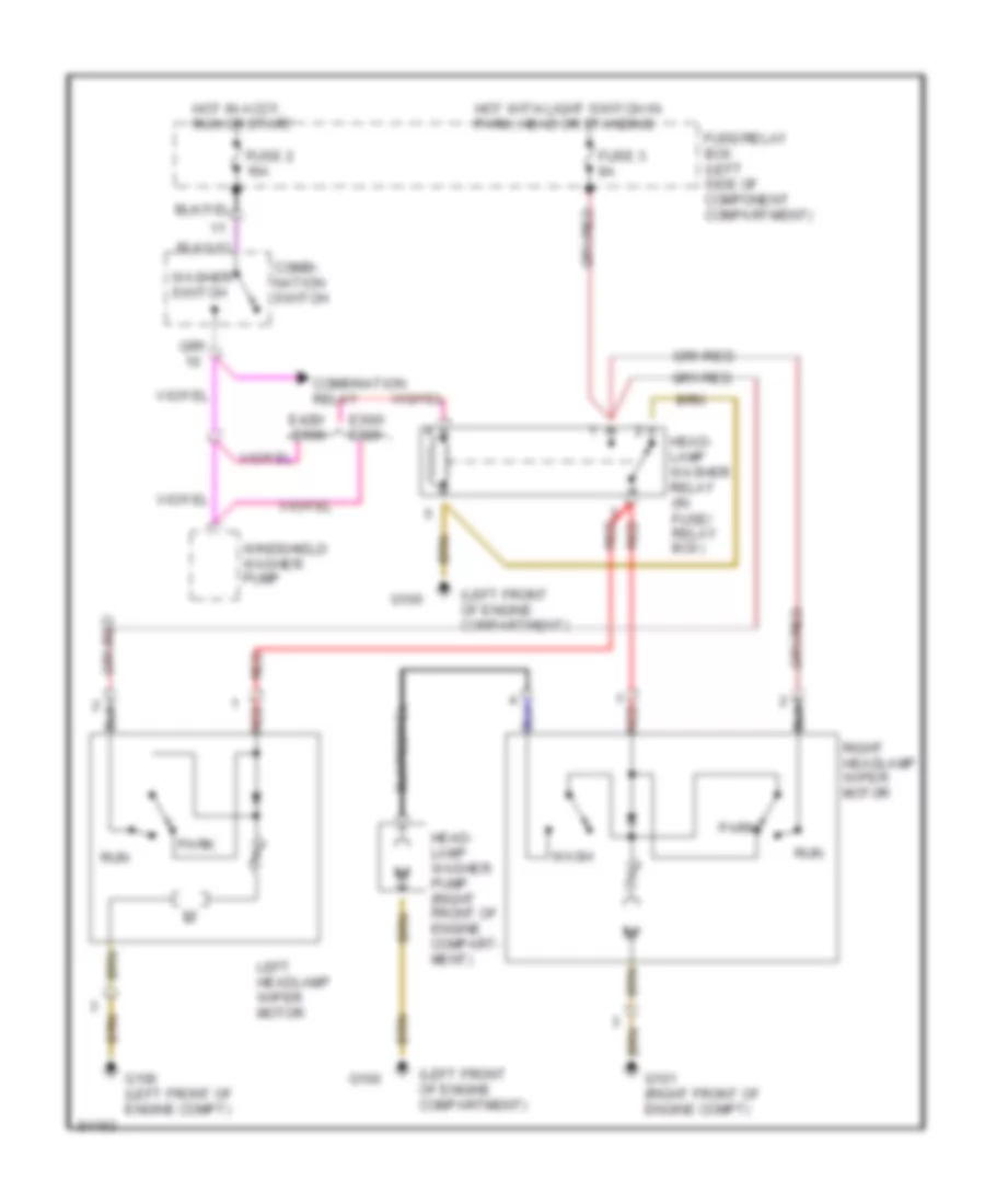
Headlight Washer/Wiper Wiring Diagram for Mercedes-Benz E320 1994
List of elements for Headlight Washer/Wiper Wiring Diagram for Mercedes-Benz E320 1994:
- (left front of engine compartment)
- Combi- nation switch
- Combination relay
- E300/ e320
- E420/ e500
- Fuse 2 16a
- Fuse 3 8a
- Fuse/relay box (left side of component compartment)
- G100
- G100 (left front of engine compt)
- G101 (right front of engine compt)
- Head- lamp washer pump (right front of engine compart- ment)
- Head- lamp washer relay (in fuse/ relay box)
- Hot in accy, run or start
- Hot with light switch in park, head or standing
- Left headlamp wiper motor
- Park
- Red
- Right headlamp wiper motor
- Run
- Wash
- Washer switch
- Windshield washer pump
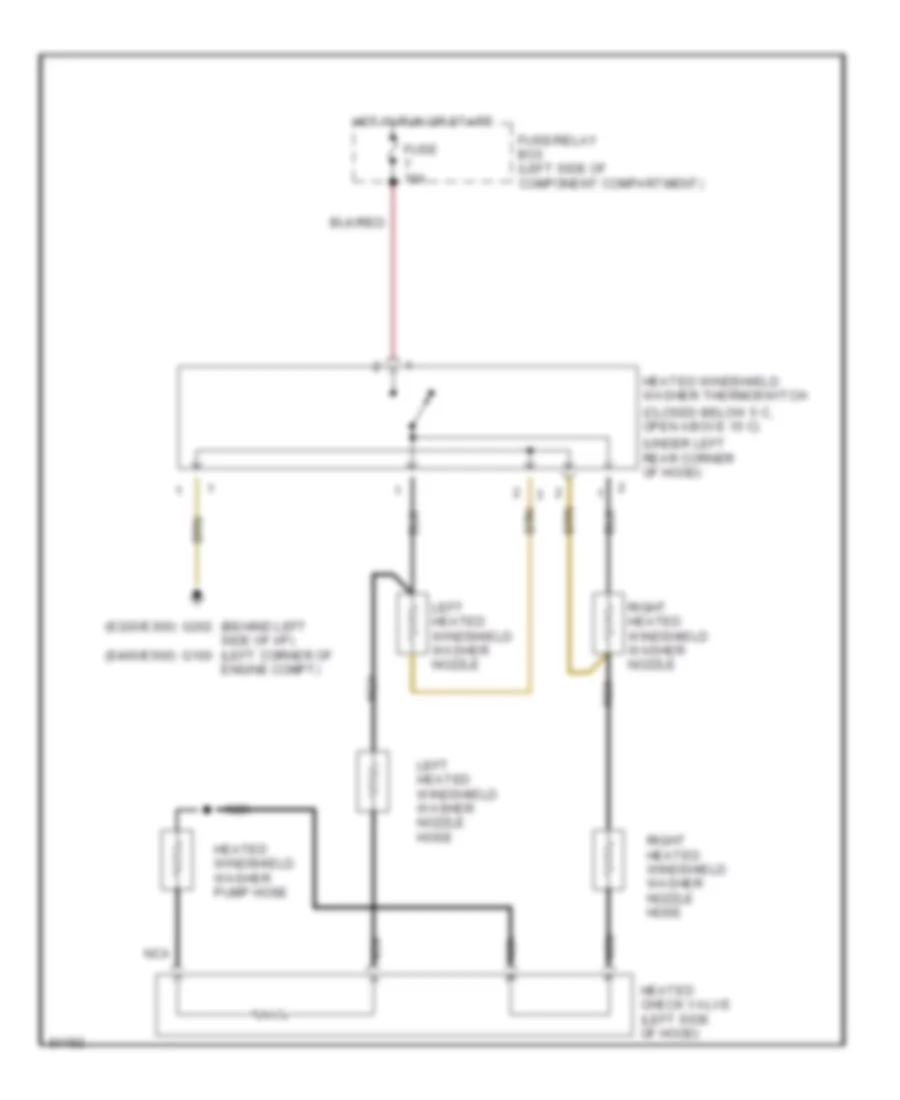
Heated Windshield Washer Wiring Diagram for Mercedes-Benz E320 1994
List of elements for Heated Windshield Washer Wiring Diagram for Mercedes-Benz E320 1994:
- (behind left side of i/p) (left corner of engine compt)
- (closed below 5 c, open above 15 c)
- (e320/e300)
- (e400/e500)
- (under left rear corner of hood)
- Fuse 16a
- Fuse/relay box (left side of component compartment)
- G100
- G202
- Heated check valve (left side of hood)
- Heated windshield washer pump hose
- Heated windshield washer thermoswitch
- Hot in run or start
- Left heated windshield washer nozzle
- Left heated windshield washer nozzle hose
- Nca
- Right heated windshield washer nozzle
- Right heated windshield washer nozzle hose
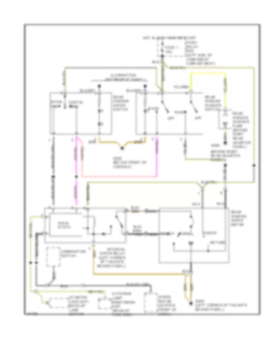
Rear Wiper/Washer Wiring Diagram for Mercedes-Benz E320 1994
List of elements for Rear Wiper/Washer Wiring Diagram for Mercedes-Benz E320 1994:
- (behind right rear quarter panel)
- (instrument panel)
- Combination switch
- Contin- uous
- Exterior lamp monitoring unit (rear of fuse box)
- Fuse 1 16a
- G302 (below front of console)
- G405
- G405 (left corner of tailgate, behind panel)
- Hot in accy, run or start
- Illumination
- Inter- val
- Interval wiper relay (left corner of tailgate, behind panel)
- Nca
- Off
- Park
- Rear window wiper motor
- Rear window washer pump (behind right rear quarter panel)
- Rear window washer switch
- Rear window wiper switch
- Return
- Solid state
- Starter lock-out/ back-up lamp switch
- Sweep
- Sweep nca
- Wash
- Wiper motor (center front of cowl)

 Čeština
 Dansk
Dansk Deutsch
 Ελληνικά
 English
 English
 Español
 Suomi
Suomi Français
 Français
 עברית
עברית Hrvatski
 Magyar
 Italiano
 日本語
日本語 한국어
한국어 Nederlands
 Polski
 Português
 Română
 Русский
 Slovenčina
 Slovenščina
 Svenska
 Türkçe
 中文 (中国)